20
159 - 2016
159 - 2016
160 - 2016
161 - 2016
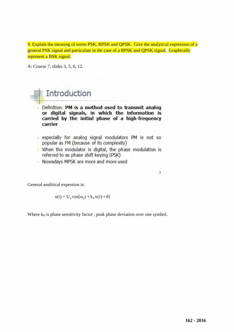
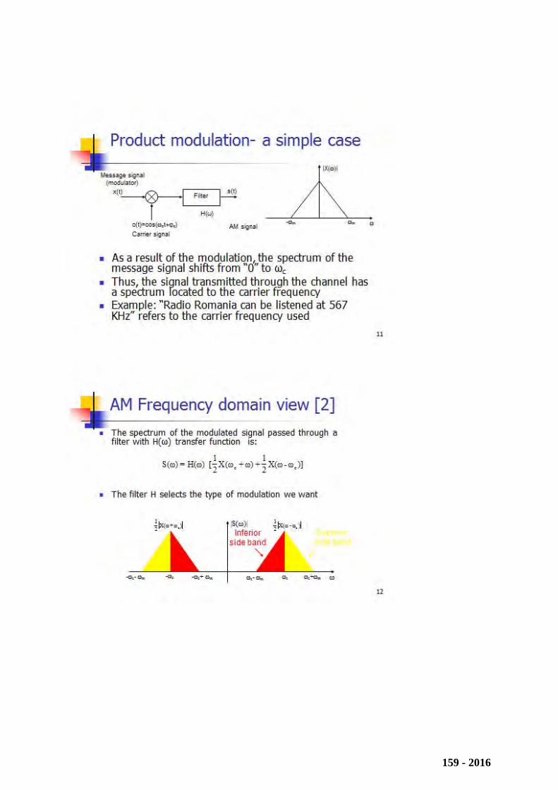
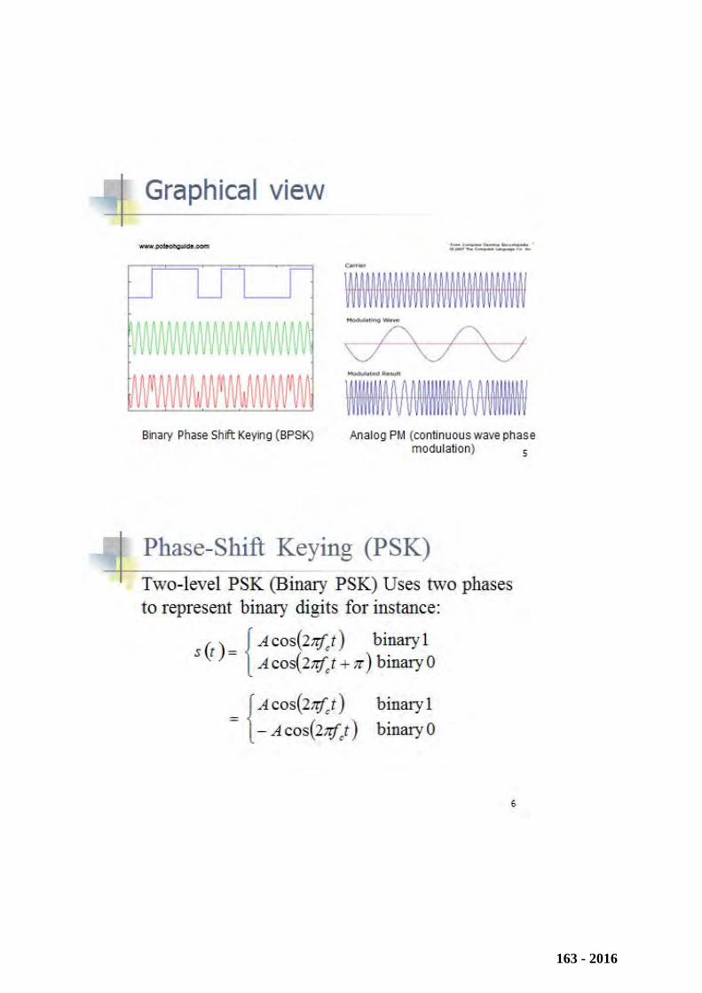
9. Explain the meaning of terms PSK, BPSK and QPSK. Give the analytical expression of a general PSK signal and particulate in the case of a BPSK and QPSK signal. Graphically represent a BSK signal.
A: Course 7, slides 3, 5, 6, 12.
General analitical expession is:
Where kP is phase sensitivity factor , peak phase deviation over one symbol.
]θ+)t(xk+tωcos[U=)t(s P00
162 - 2016
163 - 2016
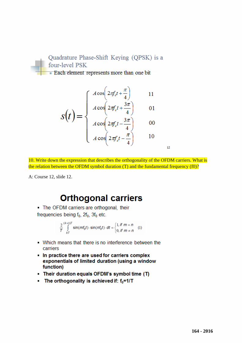
10. Write down the expression that describes the orthogonality of the OFDM carriers. What is the relation between the OFDM symbol duration (T) and the fundamental frequency (f0)?
A: Course 12, slide 12.
164 - 2016
157
Audio and Video Systems 1. Digitization parameters and data rates for voice and hi‐fi audio
https://intranet.etc.upt.ro/~AVS/Course/1_MULTIMEDIA.PDF, 15,16
High-quality stereo standard CD standard, hi-fi music, 20 kHz audio bandwidth 2 channels
for stereo recording and transmission f
E = 44.1 kHz sampling rate, according to Shannon’s theorem
n = 16 bits for quantization with SNR = 96 dB
data rate: 2 × 44.100 × 16 = 1 411 200 bits/s
Speech-quality standard telephony standard, voice, 3,4 kHz audio bandwidth 1 channel
for voice recognition f
E = 8 kHz sampling rate, according to Shannon’s theorem
n = 8 bits for quantization with SNR = 48 dB
data rate: 1 × 8.000 × 8 = 64.000 bps
2. Noise reduction principles
https://intranet.etc.upt.ro/~AVS/Course/2_SOUND.PDF, 23‐28
PPllaayybbaacckk nnooiissee rreedduuccttiioonn ((II++IIII))
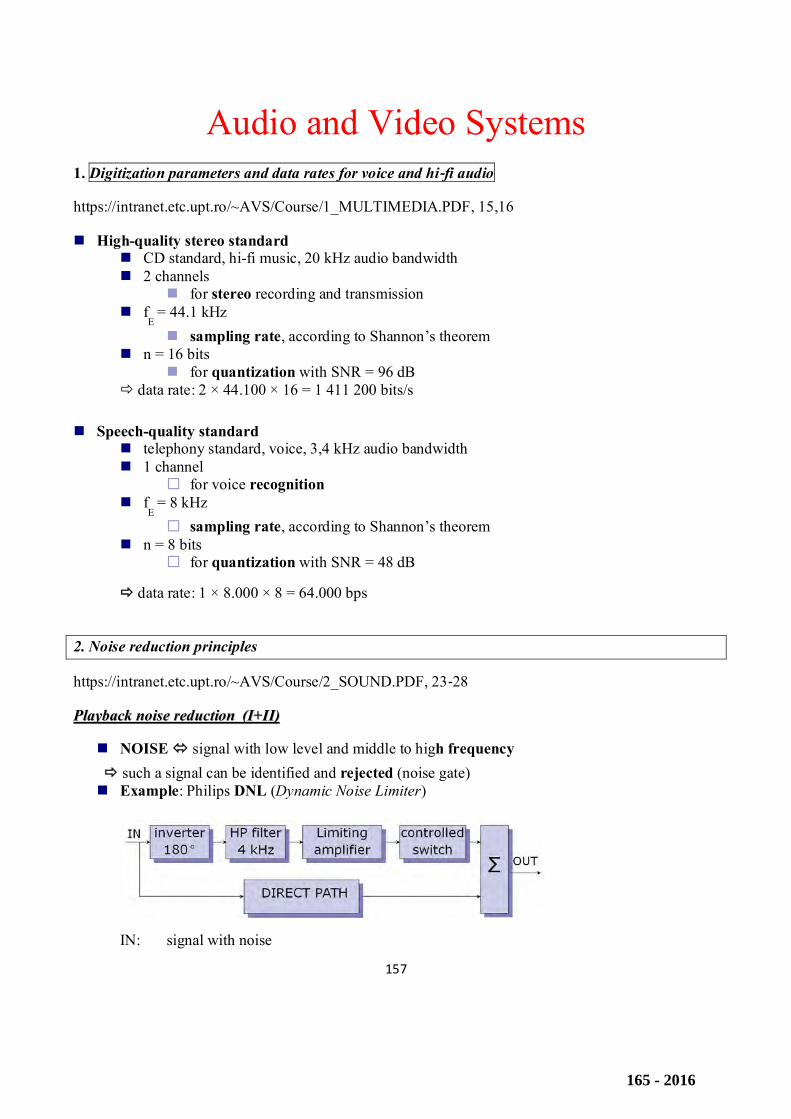
NOISE signal with low level and middle to high frequency such a signal can be identified and rejected (noise gate) Example: Philips DNL (Dynamic Noise Limiter)
IN: signal with noise
165 - 2016
158
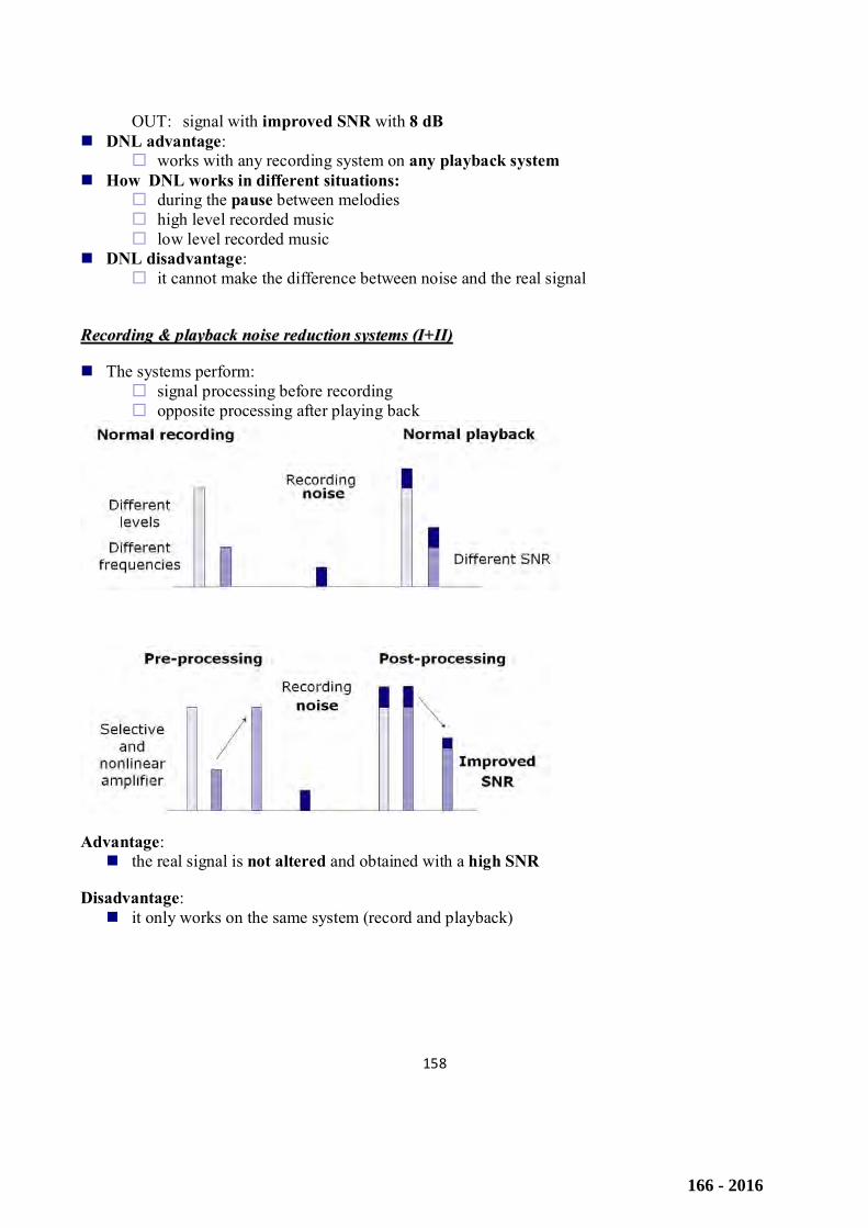
OUT: signal with improved SNR with 8 dB DNL advantage:
works with any recording system on any playback system How DNL works in different situations:
during the pause between melodies high level recorded music low level recorded music
DNL disadvantage: it cannot make the difference between noise and the real signal
RReeccoorrddiinngg && ppllaayybbaacckk nnooiissee rreedduuccttiioonn ssyysstteemmss ((II++IIII))
The systems perform: signal processing before recording opposite processing after playing back
Advantage: the real signal is not altered and obtained with a high SNR
Disadvantage: it only works on the same system (record and playback)
166 - 2016
159
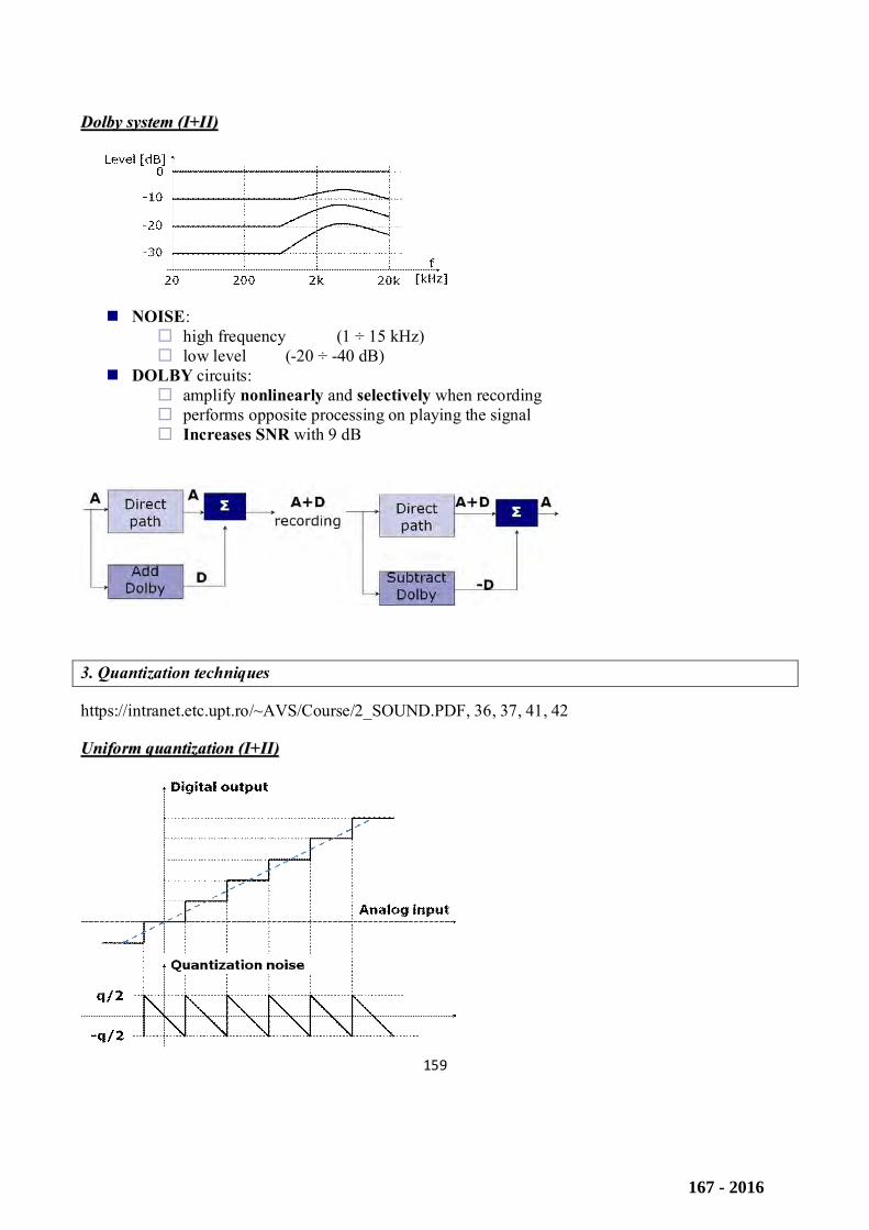
DDoollbbyy ssyysstteemm ((II++IIII))
NOISE: high frequency (1 ÷ 15 kHz) low level (-20 ÷ -40 dB)
DOLBY circuits: amplify nonlinearly and selectively when recording performs opposite processing on playing the signal Increases SNR with 9 dB
3. Quantization techniques
https://intranet.etc.upt.ro/~AVS/Course/2_SOUND.PDF, 36, 37, 41, 42
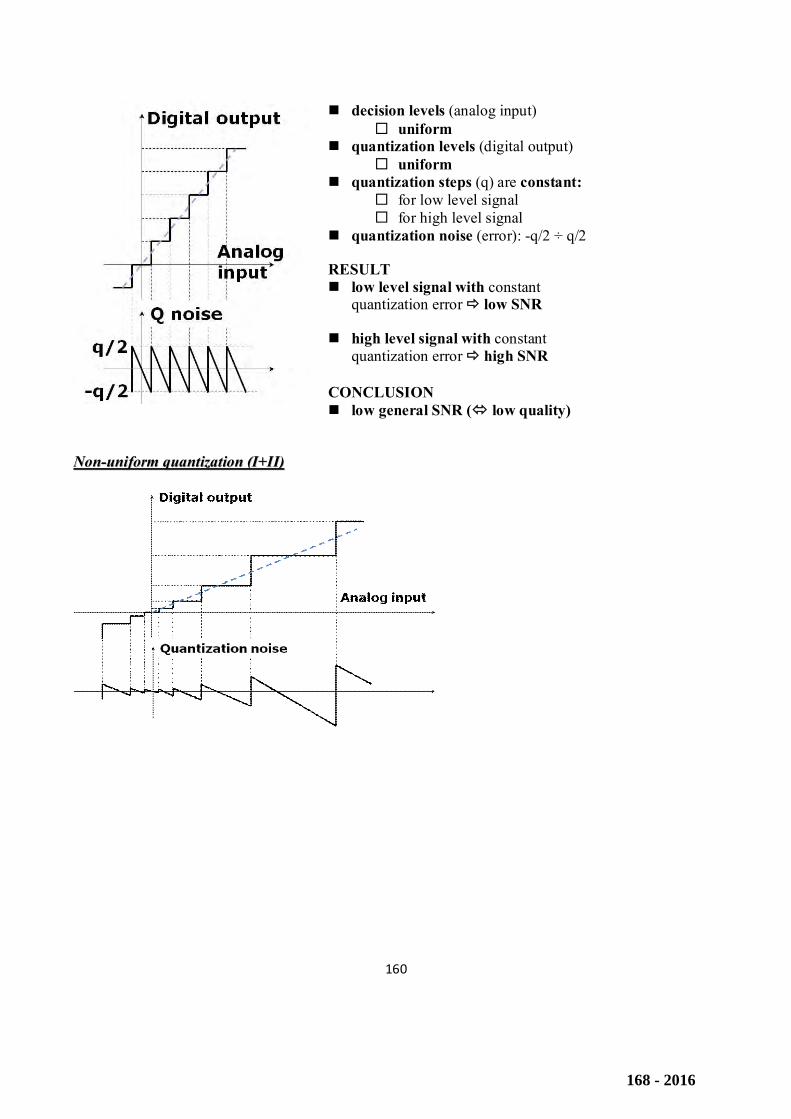
UUnniiffoorrmm qquuaannttiizzaattiioonn ((II++IIII))
167 - 2016
160
decision levels (analog input) uniform
quantization levels (digital output) uniform
quantization steps (q) are constant: for low level signal for high level signal
quantization noise (error): -q/2 ÷ q/2
RESULT low level signal with constant
quantization error low SNR
high level signal with constant quantization error high SNR
CONCLUSION low general SNR ( low quality)
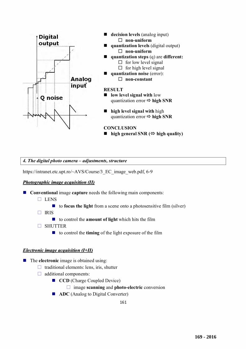
NNoonn--uunniiffoorrmm qquuaannttiizzaattiioonn ((II++IIII))
168 - 2016
161
decision levels (analog input) non-uniform
quantization levels (digital output) non-uniform
quantization steps (q) are different: for low level signal for high level signal
quantization noise (error): non-constant
RESULT low level signal with low
quantization error high SNR
high level signal with high quantization error high SNR
CONCLUSION high general SNR ( high quality)
4. The digital photo camera – adjustments, structure
https://intranet.etc.upt.ro/~AVS/Course/3_EC_image_web.pdf, 6‐9
PPhhoottooggrraapphhiicc iimmaaggee aaccqquuiissiittiioonn ((IIII))
Conventional image capture needs the following main components: LENS
to focus the light from a scene onto a photosensitive film (silver) IRIS
to control the amount of light which hits the film SHUTTER
to control the timing of the light exposure of the film
EElleeccttrroonniicc iimmaaggee aaccqquuiissiittiioonn ((II++IIII))
The electronic image is obtained using: traditional elements: lens, iris, shutter additional components:
CCD (Charge Coupled Device) image scanning and photo-electric conversion
ADC (Analog to Digital Converter)
169 - 2016
162
delivering the digital format of the image Digital storage media
electronic memory, magnetic support (disk or tape), optical support
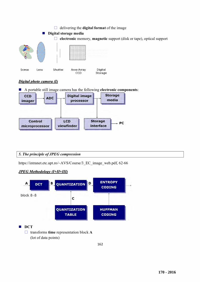
DDiiggiittaall pphhoottoo ccaammeerraa ((II))
A portable still image camera has the following electronic components:
5. The principle of JPEG compression
https://intranet.etc.upt.ro/~AVS/Course/3_EC_image_web.pdf, 62‐66
JJPPEEGG MMeetthhooddoollooggyy ((II++IIII++IIIIII))
DCT transforms time representation block A
(lot of data points)
170 - 2016
163
in frequency representation block B (few data points – few frequency components) QUANTIZATION reduces non-uniformly the accuracy of coefficients, D, according to the quantization table C
(4 tables implemented in JPEG algorithm): low frequency with higher accuracy
(small steps, non-zero values) high frequency with lower accuracy
(big steps, most values equal to zero) ENTROPY CODING
is used to obtain data compression zig-zag scanning is used to obtain long sequences of “zero”
RLE (Run-Length Encoding) - offers an excellent compression Huffman coding - is used to obtain higher compression factor
DDiissccrreettee CCoossiinnee TTrraannssffoorrmm ((II++IIII))
DCT (similar to Fourier transform) converts data from from time domain
8×8 pixels block: rows 0 ÷ 7 columns 0 ÷ 7
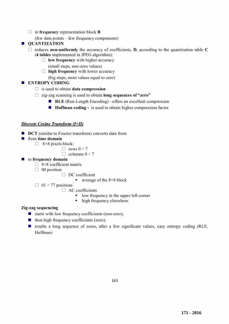
to frequency domain 8×8 coefficient matrix 00 position
DC coefficient average of the 8×8 block
01 ÷ 77 positions AC coefficients
low frequency in the upper left corner high frequency elsewhere
Zig-zag sequencing starts with low frequency coefficients (non-zero), then high frequency coefficients (zero); results a long sequence of zeros, after a few significant values, easy entropy coding (RLE,
Huffman)
171 - 2016
164
6. The composite video signal (components, parameters, TV line oscillogram)
https://intranet.etc.upt.ro/~AVS/Course/4.1_EC_TV_web.pdf, 9, 10, 12
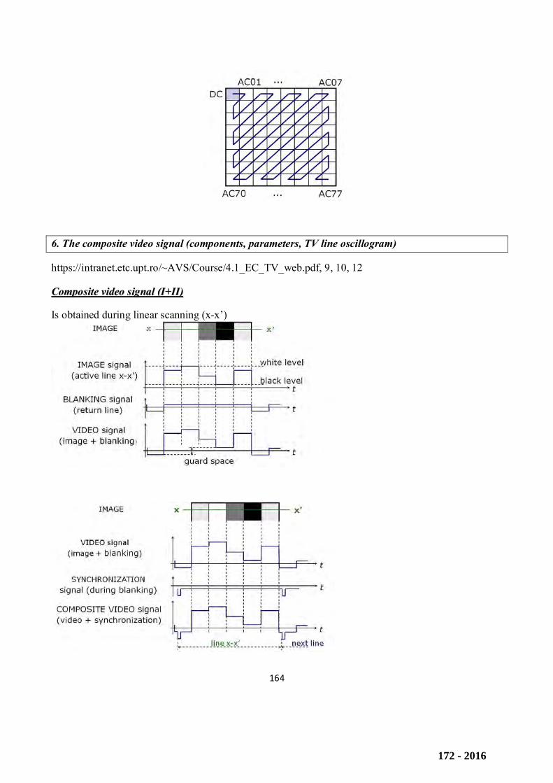
CCoommppoossiittee vviiddeeoo ssiiggnnaall ((II++IIII))
Is obtained during linear scanning (x-x’)
172 - 2016
165
FFrreeqquueennccyy ooff ccoommppoossiittee vviiddeeoo ssiiggnnaall ((IIII))
Aspect ratio 4 × 3
Vertical resolution 575 visible lines (out of 625)
Horizontal resolution For best resolution perception, the pixel must be square 4 / 3 × 575 = 766 pixels
7. Color TV signals
https://intranet.etc.upt.ro/~AVS/Course/4.1_EC_TV_web.pdf, 21‐23
CCoolloorr TTVV ssiiggnnaallss ((II++IIII))
Luminance of a (color) image is used in black-and-white television: Y = 0.3×R + 0.59×G + 0.11×B Using R, G, B signals would be incompatible with the old TV system. Compatible color TV systems use:
Y – luminance (for correct processing by black-and-white TV sets) C – chrominance
(color information only, no brightness information)
color difference signals: R-Y, G-Y, B-Y From the 4 signals, only 3 are used: luminance
Y = 0.3×R + 0.59×G + 0.11×B chrominance (2 color difference)
R-Y = 0.7×R – 0.59×G – 0.11×B B-Y = -0.3×R – 0.59×G + 0.89×B
CCoommppaattiibbllee TTVV ssiiggnnaallss ((II))
Luminance E
Y = 0.3×E
R + 0.59×E
G + 0.11×E
B = 0 ÷ 1
Color difference E
R-Y = 0.7×E
R - 0.59×E
G - 0.11×E
B = - 0.7 ÷ 0.7
173 - 2016

166
EG-Y
= - 0.3×ER
+ 0.41×EG
- 0.11×EB
= - 0.41 ÷ 0.41 (not transmitted)
EB-Y
= - 0.3×ER
- 0.59×EG
+ 0.89×EB
= - 0.89 ÷ 0.89 8.Digitization parameters, basic sampling formats and corresponding data rates for the TV signal https://intranet.etc.upt.ro/~AVS/Course/4.5_E_DTV_web.pdf, 3‐5, 12, 13
DDiiggiittaall TTVV ssttuuddiioo ssttaannddaarrdd ((II++IIII++IIIIII))
1982, CCIR Rec.601 – USA/Europe standard NTSC / SECAM / PAL 525 / 625 lines
common digital TV line same bit rate same quality easy system conversion
TV components (Y, R-Y, B-Y) orthogonal sampling standard sampling frequency
fS = 13,5 MHz
PCM format 8 bits / component sample
174 - 2016
167
DDiiggiittaall tteelleevviissiioonn ssiiggnnaall bbiitt rraattee
Digital signal bit rate D = f
S × n [bits/s]
TV signal bit rate D = D
Y + D
R-Y + D
B-Y
= fS Y
× nY + f
S R-Y × n
R-Y + f
S B-Y × n
B-Y
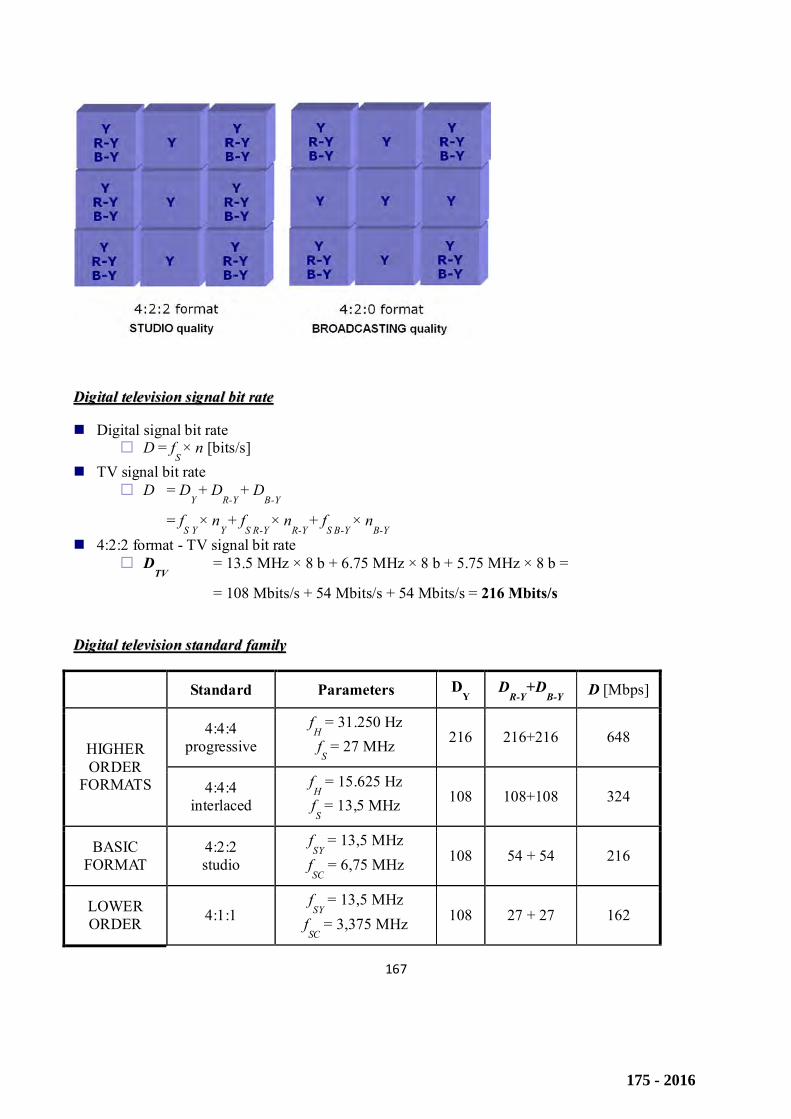
4:2:2 format - TV signal bit rate D
TV = 13.5 MHz × 8 b + 6.75 MHz × 8 b + 5.75 MHz × 8 b =
= 108 Mbits/s + 54 Mbits/s + 54 Mbits/s = 216 Mbits/s
DDiiggiittaall tteelleevviissiioonn ssttaannddaarrdd ffaammiillyy
Standard Parameters DY D
R-Y+D
B-Y D [Mbps]
HIGHER ORDER
FORMATS
4:4:4 progressive
fH = 31.250 Hz fS = 27 MHz 216 216+216 648
4:4:4 interlaced
fH = 15.625 Hz
fS = 13,5 MHz 108 108+108 324
BASIC FORMAT
4:2:2 studio
fSY
= 13,5 MHz fSC
= 6,75 MHz 108 54 + 54 216
LOWER ORDER 4:1:1
fSY
= 13,5 MHz fSC
= 3,375 MHz 108 27 + 27 162
175 - 2016
168
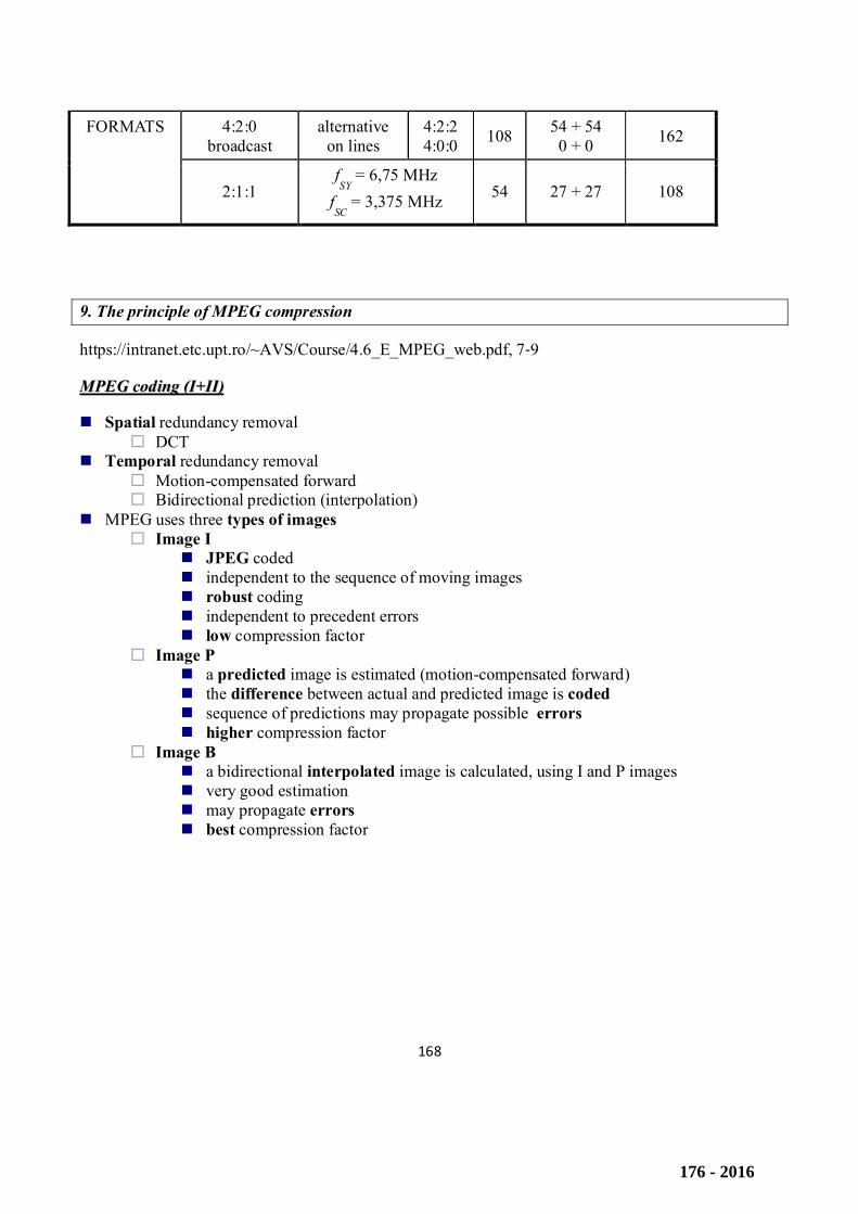
FORMATS 4:2:0 broadcast
alternative on lines
4:2:2 4:0:0 108 54 + 54
0 + 0 162
2:1:1 fSY
= 6,75 MHz fSC
= 3,375 MHz 54 27 + 27 108
9. The principle of MPEG compression
https://intranet.etc.upt.ro/~AVS/Course/4.6_E_MPEG_web.pdf, 7‐9
MMPPEEGG ccooddiinngg ((II++IIII))
Spatial redundancy removal DCT
Temporal redundancy removal Motion-compensated forward Bidirectional prediction (interpolation)
MPEG uses three types of images Image I
JPEG coded independent to the sequence of moving images robust coding independent to precedent errors low compression factor
Image P a predicted image is estimated (motion-compensated forward) the difference between actual and predicted image is coded sequence of predictions may propagate possible errors higher compression factor
Image B a bidirectional interpolated image is calculated, using I and P images very good estimation may propagate errors best compression factor
176 - 2016
169
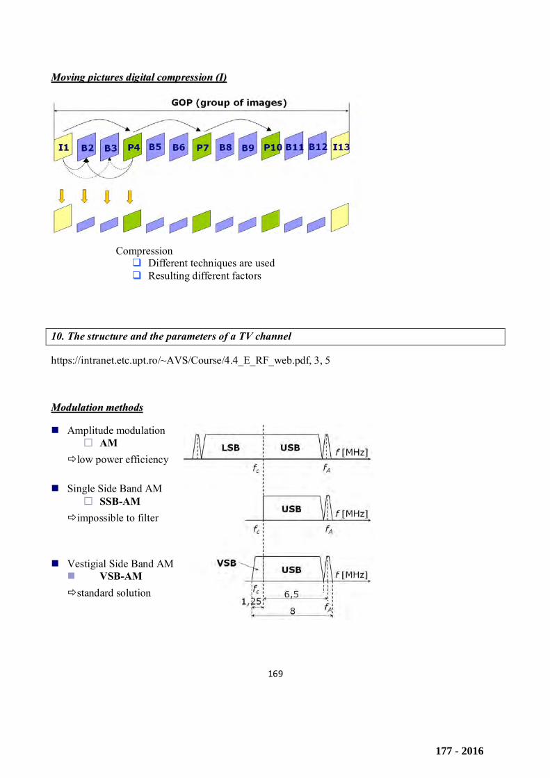
MMoovviinngg ppiiccttuurreess ddiiggiittaall ccoommpprreessssiioonn ((II))
Compression Different techniques are used Resulting different factors
10. The structure and the parameters of a TV channel
https://intranet.etc.upt.ro/~AVS/Course/4.4_E_RF_web.pdf, 3, 5
MMoodduullaattiioonn mmeetthhooddss
Amplitude modulation AM
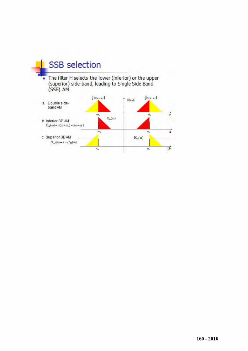
low power efficiency Single Side Band AM
SSB-AM impossible to filter
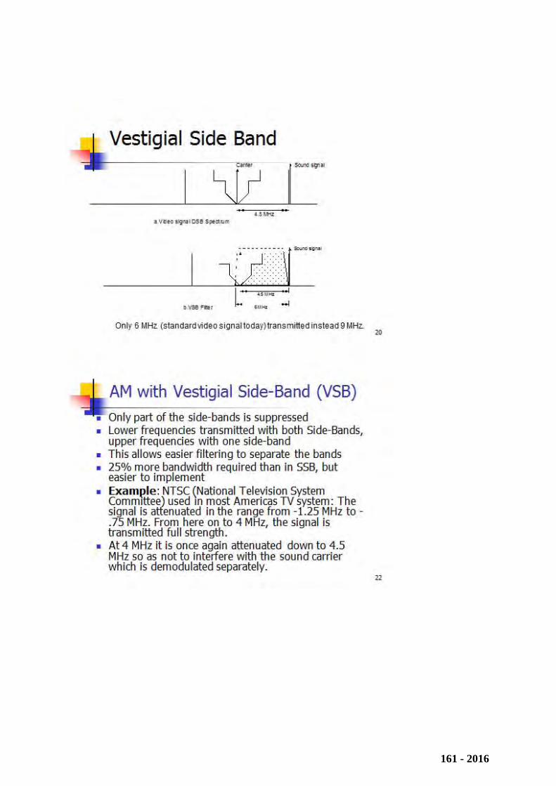
Vestigial Side Band AM VSB-AM standard solution
177 - 2016
170
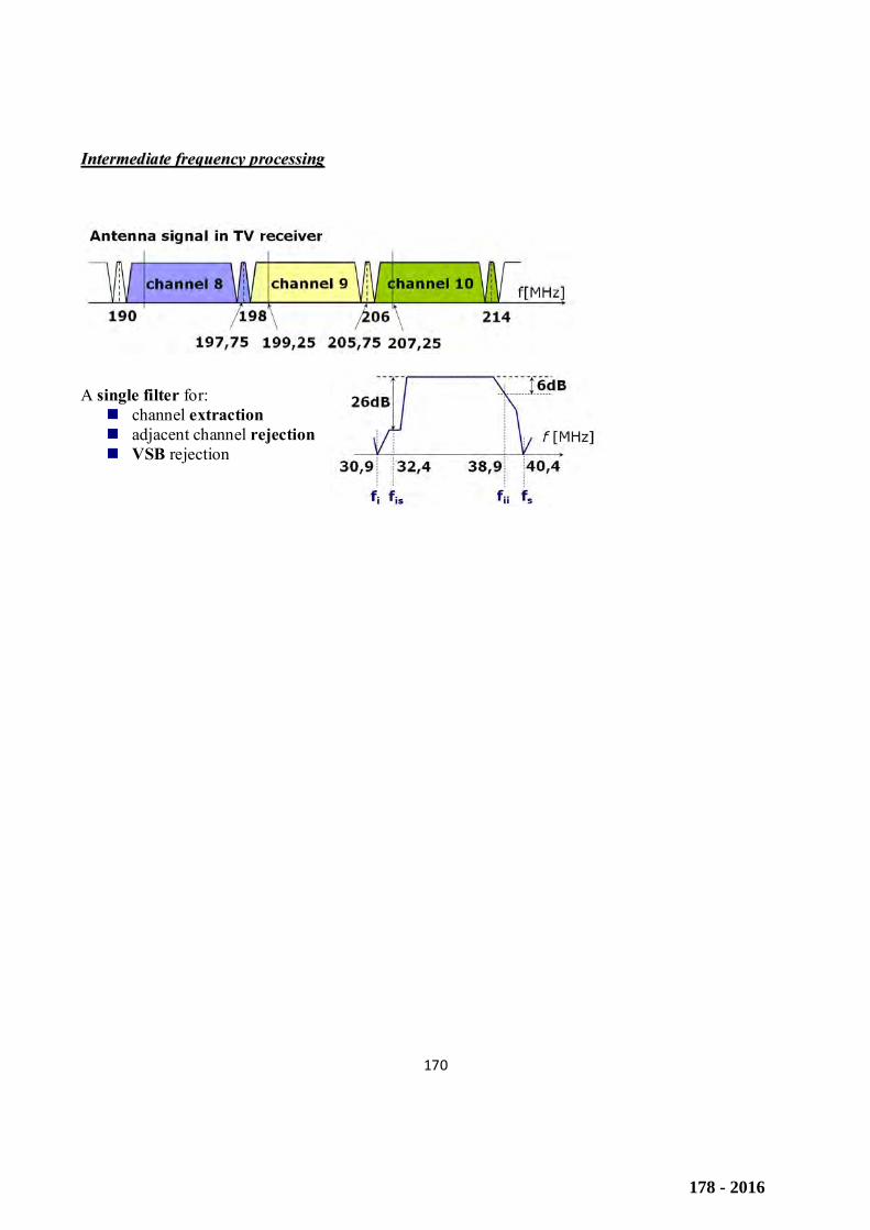
IInntteerrmmeeddiiaattee ffrreeqquueennccyy pprroocceessssiinngg
A single filter for: channel extraction adjacent channel rejection VSB rejection
178 - 2016


