SAVE THIS MANUALKeep this manual for the safety warnings
and precautions, assembly, operating, inspection, maintenance and cleaning procedures. Write the product’s serial number in the back of the manual near the assembly diagram (or month and year of purchase if product has no number). Keep this manual and the receipt in a safe and dry place for future reference.
IMPORTANT SAFETY INFORMATION
In this manual, on the labeling, and all other information provided with this product:
This is the safety alert symbol. It is used to alert you to potential personal injury hazards. Obey all safety messages that follow this symbol to avoid possible injury or death.
DANGER indicates a hazardous situation
which, if not avoided, will result in death or serious injury.
WARNING indicates a hazardous situation
which, if not avoided, could result in death or serious injury.
CAUTION, used with the safety alert
symbol, indicates a hazardous situation which, if not avoided, could result in minor or moderate injury.
NOTICE is used to address practices not
related to personal injury.
CAUTION, without the safety alert symbol, is
used to address practices not related to personal injury.
General Safety Warnings WARNING! Read all safety warnings and instructions. Save all warnings and instructions for future reference.
Laser Light. Avoid direct eye
exposure.
1. Do not direct the laser beam into the eyes of any person or animal. Doing so may cause severe injury to the eye.
2. Verify Laser Level is in the “Off” position before making any adjustments or changing the batteries.
3. Position batteries in proper polarity and do not install batteries of different types, charge levels, or capacities together.
4. Remove batteries if Laser Level is not to be used for a long period of time.
5. The Laser Level is a delicate instrument; do not drop or jar the Laser Level.
6. Wear ANSI-approved safety goggles and heavy-duty work gloves during use.
7. Keep work area clean and well lit.
8. This product is not a toy. Keep it out of reach of children.
9. Keep children and bystanders away while operating Laser Level.
10. Inspect before every use; do not use if parts loose or damaged.
11. Stay alert, watch what you are doing and use common sense when operating Laser Level. Do not use Laser Level while you are tired or under the influence of drugs, alcohol or medication.
12. Dress properly. Do not wear loose clothing or jewelry. Keep your hair, clothing and gloves away from moving parts.
13. Maintain labels and nameplates on the tool. These carry important safety information. If unreadable or missing, contact Harbor Freight Tools for a replacement.
14. WARNING: This product contains or, when used, produces a chemical known to the State of California to cause cancer and birth defects or other reproductive harm. (California Health & Safety Code § 25249.5, et seq.)
15. The warnings, precautions, and instructions discussed in this instruction manual cannot cover all possible conditions and situations that may occur. It must be understood by the operator that common sense and caution are factors which cannot be built into this product, but must be supplied by the operator.
SAVE THESE INSTRUCTIONS.
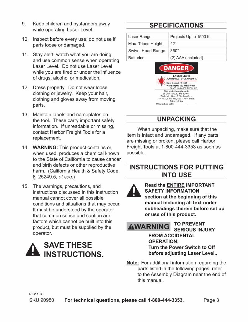
SPECIFICATIONSLaser Range Projects Up to 1500 ft.
Max. Tripod Height 42”
Swivel Head Range 360°
Batteries (2) AAA (included)
DANGERLASER LIGHT
AVOID DIRECT EYE EXPOSURE
Max. Output: <5 mW,Wavelength: 650 nm ± 10 nm
CLASS IIIa LASER PRODUCTThis product complies with
21 CFR 1040.10 and 1040.11Diode Mfr.: Sean & Stephen Corp.
4F, NO3, Lane 335, Sec 4, Hsin-Yi Rd.Taipen, China
Manufacture Date: ___________, _______
UNPACKINGWhen unpacking, make sure that the
item is intact and undamaged. If any parts are missing or broken, please call Harbor Freight Tools at 1-800-444-3353 as soon as possible.
INSTRUCTIONS FOR PUTTING INTO USE
Read the ENTIRE IMPORTANT SAFETY INFORMATION section at the beginning of this manual including all text under subheadings therein before set up or use of this product.
TO PREVENT SERIOUS INJURY
FROM ACCIDENTAL OPERATION: Turn the Power Switch to Off before adjusting Laser Level..
Note: For additional information regarding the parts listed in the following pages, refer to the Assembly Diagram near the end of this manual.
assembly prior to use. Read entire manual to become familiar with product BEFORE you use the Laser Level. Be sure you have all parts described in the Parts List and Assembly Diagram located on the last page of this manual.
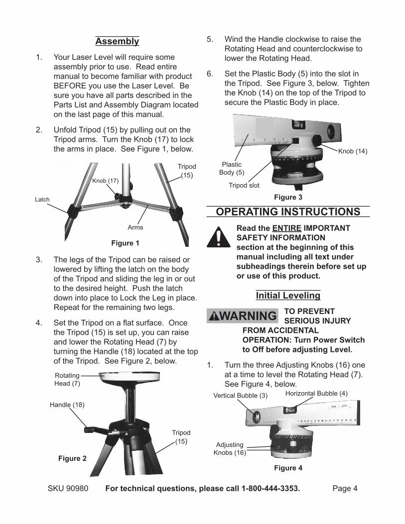
2. Unfold Tripod (15) by pulling out on the Tripod arms. Turn the Knob (17) to lock the arms in place. See Figure 1, below.
3. The legs of the Tripod can be raised or lowered by lifting the latch on the body of the Tripod and sliding the leg in or out to the desired height. Push the latch down into place to Lock the Leg in place. Repeat for the remaining two legs.
4. Set the Tripod on a flat surface. Once the Tripod (15) is set up, you can raise and lower the Rotating Head (7) by turning the Handle (18) located at the top of the Tripod. See Figure 2, below.
5. Wind the Handle clockwise to raise the Rotating Head and counterclockwise to lower the Rotating Head.
6. Set the Plastic Body (5) into the slot in the Tripod. See Figure 3, below. Tighten the Knob (14) on the top of the Tripod to secure the Plastic Body in place.
OPERATING INSTRUCTIONS Read the ENTIRE IMPORTANT
SAFETY INFORMATION section at the beginning of this manual including all text under subheadings therein before set up or use of this product.
Initial Leveling TO PREVENT
SERIOUS INJURY FROM ACCIDENTAL OPERATION: Turn Power Switch to Off before adjusting Level.
1. Turn the three Adjusting Knobs (16) one at a time to level the Rotating Head (7). See Figure 4, below.
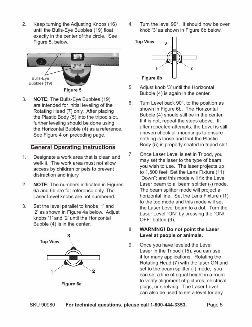
2. Keep turning the Adjusting Knobs (16) until the Bulls-Eye Bubbles (19) float exactly in the center of the circle. See Figure 5, below.
3. NOTE: The Bulls-Eye Bubbles (19) are intended for initial leveling of the Rotating Head (7) only. After placing the Plastic Body (5) into the tripod slot, further leveling should be done using the Horizontal Bubble (4) as a reference. See Figure 4 on preceding page.
General Operating Instructions1. Designate a work area that is clean and
well-lit. The work area must not allow access by children or pets to prevent distraction and injury.
2. NOTE: The numbers indicated in Figures 6a and 6b are for reference only. The Laser Level knobs are not numbered.
3. Set the level parallel to knobs ‘1’ and ‘2’ as shown in Figure 4a below. Adjust knobs ‘1’ and ‘2’ until the Horizontal Bubble (4) is in the center.
4. Turn the level 90°. It should now be over knob ‘3’ as shown in Figure 6b below.
5. Adjust knob ‘3’ until the Horizontal Bubble (4) is again in the center.
6. Turn Level back 90°, to the position as shown in Figure 6b. The Horizontal Bubble (4) should still be in the center. If it is not, repeat the steps above. If, after repeated attempts, the Level is still uneven check all mountings to ensure nothing is loose and that the Plastic Body (5) is properly seated in tripod slot.
7. Once Laser Level is set in Tripod, you may set the laser to the type of beam you wish to use. The laser projects up to 1,500 feet. Set the Lens Fixture (11) “Down”; and this mode will fix the Level Laser beam to a beam splitter (-) mode. The beam splitter mode will project a horizontal line. Set the Lens Fixture (11) to the top mode and this mode will set the Laser Level beam to a dot. Turn the Laser Level “ON” by pressing the “ON/OFF” button (9).
8. WARNING! Do not point the Laser Level at people or animals.
9. Once you have leveled the Level Laser in the Tripod (15), you can use it for many applications. Rotating the Rotating Head (7) with the laser ON and set to the beam splitter (-) mode, you can set a line of equal height in a room to verify alignment of pictures, electrical plugs, or shelving. The Laser Level can also be used to set a level for any
surface while providing a bright beam to mark your settings by.
MAINTENANCE AND SERVICING
Proceduresnotspecificallyexplained in this manual must beperformedonlybyaqualifiedtechnician.
TO PREVENT SERIOUS INJURY
FROM ACCIDENTAL OPERATION: Turn the OFF the Laser Level before performing any inspection, maintenance, or cleaning procedures.
TO PREVENT SERIOUS INJURY FROM TOOL FAILURE: Do not use damaged equipment. If abnormal noise or vibration occurs, have the problem corrected before further use.
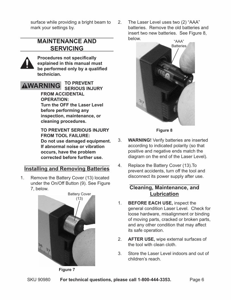
Installing and Removing Batteries1. Remove the Battery Cover (13) located
under the On/Off Button (9). See Figure 7, below.
2. The Laser Level uses two (2) “AAA” batteries. Remove the old batteries and insert two new batteries. See Figure 8, below.
3. WARNING! Verify batteries are inserted according to indicated polarity (so that positive and negative ends match the diagram on the end of the Laser Level).
4. Replace the Battery Cover (13).To prevent accidents, turn off the tool and disconnect its power supply after use.
Cleaning, Maintenance, and Lubrication
1. BEFORE EACH USE, inspect the general condition Laser Level. Check for loose hardware, misalignment or binding of moving parts, cracked or broken parts, and any other condition that may affect its safe operation.
2. AFTER USE, wipe external surfaces of the tool with clean cloth.
3. Store the Laser Level indoors and out of children’s reach.
PLEASE READ THE FOLLOWING CAREFULLYTHE MANUFACTURER AND/OR DISTRIBUTOR HAS PROVIDED THE PARTS LIST AND ASSEMBLY DIAGRAM IN THIS MANUAL AS A REFERENCE TOOL ONLY. NEITHER THE MANUFACTURER OR DISTRIBUTOR MAKES ANY REPRESENTATION OR WARRANTY OF ANY KIND TO THE BUYER THAT HE OR SHE IS QUALIFIED TO MAKE ANY REPAIRS TO THE PRODUCT, OR THAT HE OR SHE IS QUALIFIED TO REPLACE ANY PARTS OF THE PRODUCT. IN FACT, THE MANUFACTURER AND/OR DISTRIBUTOR EXPRESSLY STATES THAT ALL REPAIRS AND PARTS REPLACEMENTS SHOULD BE UNDERTAKEN BY CERTIFIED AND LICENSED TECHNICIANS, AND NOT BY THE BUYER. THE BUYER ASSUMES ALL RISK AND LIABILITY ARISING OUT OF HIS OR HER REPAIRS TO THE ORIGINAL PRODUCT OR REPLACEMENT PARTS THERETO, OR ARISING OUT OF HIS OR HER INSTALLATION OF REPLACEMENT PARTS THERETO.
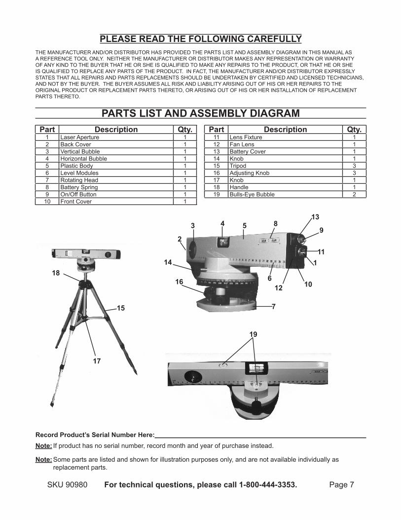
PARTS LIST AND ASSEMBLY DIAGRAM
Record Product’s Serial Number Here: Note: If product has no serial number, record month and year of purchase instead.
Note: Some parts are listed and shown for illustration purposes only, and are not available individually as replacement parts.