16 Multicyclone Arrangements In this chapter we wish to briefly discuss two types of multi-unit arrangements used in cyclone and swirl tube installations in industry. We also give some guidelines for the choice of arrangement in a given application including a worked example given in Appendix 16A. In addition, we briefly describe how to apply the modeling equations outlined in previous chapters to multicyclone arrangements. There are many situations wherein one cyclone or swirl tube is inadequate for the separation task at hand. In such situations, it is often feasible to use multiple units either in series or in parallel or both. 16.1 Cyclones in Series When the solids concentration is high, and the emission from just one sep- arator stage would be too high, a second – or even a third – separator can be added in series with the first stage separator to collect additional solids. Such an arrangement is sketched in Fig. 16.1.1. It is customary to refer to the individual stages as the ‘primary’, ‘secondary’, and ‘tertiary’ stages or as the ‘first’, ‘second’, and ‘third’ stage. In some industries, the primary cyclone is also called a ‘rough-cut’ cyclone despite the fact that its overall efficiency (mainly arising from high inlet mass loading) will normally greatly exceed the efficiency of subsequent stages. As seen in the figure, the overflow from the first cyclone (stage I) is charged to the second one (stage II) and so on. Cyclones working in series can be mod- eled using the same equations as for a single cyclone. To predict the separation efficiency of stage II or stage III, it is necessary to know the concentration and the size distribution of the feed solids, which is the concentration and size dis- tribution in the overflow from the cyclone stage immediately preceding it. In addition, any significant decrease in pressure or change in temperature across a prior stage requires a recomputation of the gas flow rate, viscosity and den- sity reporting to the following stage. If any additional ‘outside’ streams are
Transcript
16
Multicyclone Arrangements
In this chapter we wish to briefly discuss two types of multi-unit arrangementsused in cyclone and swirl tube installations in industry. We also give someguidelines for the choice of arrangement in a given application including aworked example given in Appendix 16A. In addition, we briefly describe howto apply the modeling equations outlined in previous chapters to multicyclonearrangements.
There are many situations wherein one cyclone or swirl tube is inadequatefor the separation task at hand. In such situations, it is often feasible to usemultiple units either in series or in parallel or both.
16.1 Cyclones in Series
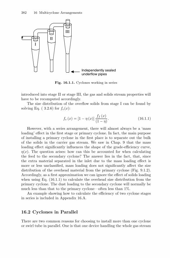
When the solids concentration is high, and the emission from just one sep-arator stage would be too high, a second – or even a third – separator canbe added in series with the first stage separator to collect additional solids.Such an arrangement is sketched in Fig. 16.1.1. It is customary to refer tothe individual stages as the ‘primary’, ‘secondary’, and ‘tertiary’ stages or asthe ‘first’, ‘second’, and ‘third’ stage. In some industries, the primary cycloneis also called a ‘rough-cut’ cyclone despite the fact that its overall efficiency(mainly arising from high inlet mass loading) will normally greatly exceed theefficiency of subsequent stages.
As seen in the figure, the overflow from the first cyclone (stage I) is chargedto the second one (stage II) and so on. Cyclones working in series can be mod-eled using the same equations as for a single cyclone. To predict the separationefficiency of stage II or stage III, it is necessary to know the concentration andthe size distribution of the feed solids, which is the concentration and size dis-tribution in the overflow from the cyclone stage immediately preceding it. Inaddition, any significant decrease in pressure or change in temperature acrossa prior stage requires a recomputation of the gas flow rate, viscosity and den-sity reporting to the following stage. If any additional ‘outside’ streams are
382 16 Multicyclone Arrangements
I II
III
Independently sealed underflow pipes
Fig. 16.1.1. Cyclones working in series
introduced into stage II or stage III, the gas and solids stream properties willhave to be recomputed accordingly.
The size distribution of the overflow solids from stage I can be found bysolving Eq. ( 3.2.6) for fe(x):
fe (x) = [1 − η (x)]ff (x)(1 − η)
. (16.1.1)
However, with a series arrangement, there will almost always be a ‘massloading’ effect in the first stage or primary cyclone. In fact, the main purposeof installing a primary cyclone in the first place is to separate out the bulkof the solids in the carrier gas stream. We saw in Chap. 9 that the massloading effect significantly influences the shape of the grade-efficiency curve,η(x). The question arises: how can this be accounted for when calculatingthe feed to the secondary cyclone? The answer lies in the fact, that, sincethe extra material separated in the inlet due to the mass loading effect ismore or less unclassified, mass loading does not significantly affect the sizedistribution of the overhead material from the primary cyclone (Fig. 9.1.2).Accordingly, as a first approximation we can ignore the effect of solids loadingwhen using Eq. (16.1.1) to calculate the overhead size distribution from theprimary cyclone. The dust loading to the secondary cyclone will normally bemuch less than that to the primary cyclone—often less than 1%.
An example showing how to calculate the efficiency of two cyclone stagesin series is included in Appendix 16.A.
16.2 Cyclones in Parallel
There are two common reasons for choosing to install more than one cycloneor swirl tube in parallel. One is that one device handling the whole gas stream
16.2 Cyclones in Parallel 383
would become too large for practical purposes. The other is that the cut sizeobtained with one large cyclone or swirl tube would be too large to achievethe required separation efficiency. This latter consideration can be understoodas follows.
Consider Eq. (5.2.1):
x50 =
√vrCS9µDx
ρpv2θCS
.
If geometrically similar cyclones or swirl tubes of different sizes are operatedat the same inlet velocity, vrCS and vθCS will also be similar. The equationtherefore shows that the cut size is roughly proportional to the square root ofthe vortex finder diameter. Thus, in geometrically similar cyclones, the cut sizewill be proportional to the square root of the characteristic cyclone dimension,say D. Incidentally, since vθCS and vrCS are proportional to the inlet andoutlet velocities, it can be also observed from inspection of Equation (5.2.1)that the cut size for geometrically similar cyclones is inversely proportional tothe square root of any characteristic velocity such as the gas superficial inletor outlet velocity.
Additionally, Eqs. (4.3.18) and (4.3.19) indicate that the Euler numberand, therefore, the pressure drop, are independent of the cyclone size for geo-metrically similar cyclones or swirl tubes if the inlet velocity is kept constant.We can thus gain in efficiency without increasing pressure drop by splittingup the solid-laden process stream over two or more cyclones or swirl tubesand operating them in parallel.
When designing parallel cyclones, the overriding concern is that the gasand solids be distributed evenly between the various units. One way of achiev-ing this is to design and arrange the cyclones or swirl tubes in such a mannerthat each individual unit experiences the same total pressure (dynamic andstatic) and that the gas exiting each gas outlet pipe experiences the same flowresistance. These two criteria normally can be met by rendering both the inletand overflow piping as symmetrical as possible. Since it is often impractical todesign perfectly symmetrical overflow piping or ducting, the piping should belarge enough so that its resistance is negligible compared to the pressure dropacross the cyclones, even if the piping is not identical (in length or number ofbends, for example).
Under high solids or liquid loading, special attention also must be directedtowards achieving uniform solids or liquid distribution. At some point in theupstream piping the incoming gas/solids mixture will usually encounter abend which will tend to segregate the incoming solids to its outer wall. Thiscan lead to solids maldistribution in the inlet piping and, in turn, hopper‘crossflow’ as discussed in Chap. 11. For this reason, bends should be locatedwell ahead of any parallel bank of cyclones – preferably 10 pipe diameters orits equivalent.
384 16 Multicyclone Arrangements
Parallel arrangements of cyclones come in a wide variety of configurations.Their inlet distributor geometry is normally comprised of either:
1. a segmented section of rectangular ducting, such as that shown in topportion of Fig. 16.2.1, or
2. a common casing or chamber into which the inlet gas-solids enters priorto dividing and flowing to the individual cyclones. Examples are shownin Figs. 16.2.2 and 16.2.3. Cyclones whose feed consists of gas-solids en-trainment off a fluidized bed also fall into this category.
Fig. 16.2.1. A series and parallel arrangement of cyclones in a USA particleboardclean-up facility. Courtesy of Polutrol-Europe
One commercially available system comprising a parallel arrangement ofcyclones, called ‘swirl tubes’, is the multicyclone unit illustrated in Fig. 16.2.2.The solids-bearing feed stream enters the separator vessel via a centrally lo-cated pipe at the top of the vessel. The feed exits this inlet pipe near itsbottom end from where it flows radially outwards – between two tube sheets- and into the feed chamber or plenum. The solids-bearing gas then enters theindividual ‘swirl tubes’ wherein it is split into a solids-laden underflow streamand a ‘clean-gas’ overflow stream.
Figure 16.2.3 shows another commercial multicyclone featuring closelyspaced individual ‘swirl tubes’ arranged on a tube sheet but fed from oneside of the tube array.
The three installations shown in Figs. 16.2.2 and 16.2.3 illustrate only afew of many possible multicyclone arrangements. Each equipment designer
16.2 Cyclones in Parallel 385
or manufacturer has his own preferred design geometry or geometries andexperiences regarding cyclone design, tube layout, plenum design and mannerof addressing the flow distribution issue. The various arrays offered by theequipment manufactures differ mostly in their inlet arrangements and thegeometry of the cyclone layout.
A true ‘multicyclone’ is not only a parallel arrangement of cyclones, butalso one wherein the individual cyclones are housed within a common casingthat constitutes the inlet chamber. Furthermore, the dust (or liquid) dischargeand the gas outlet pipes also report to their own common outlet plenum andhopper, respectively. Multicyclone systems of the type shown in Figs. 16.2.2and 16.2.3 are usually comprised of numerous small diameter cyclones (typ-ically under 250 mm in diameter) and this normally leads to excellent sep-aration performance relative to fewer, larger units handling the same totalvolumetric flow.
Swirl tubes
Gas inlet plenum
Solids outlet plenum
Gas outlet plenum
Fig. 16.2.2. Shell third-stage separator with swirl tubes working in parallel. Cour-tesy Shell Global Solutions International
Another way of arranging cyclones in parallel is shown in Figs. 16.2.4and 16.2.5. Unlike multicyclones, these cyclones are not enclosed inside a sep-arate housing, are not arranged on a common tube-sheet, are external, and areusually larger than the cyclones comprising a multicyclone installation. Theystill, however, take their feed from a common inlet duct and their overflowpipes and solids discharge openings report to common collection chambers.
Some inlet headers or distributors are in-line; others are circular. The cir-cular arrangement usually provides the most uniform flow distribution but
386 16 Multicyclone Arrangements
Clean gas
Dust ladengas
Dust discharge
Dust ladengas
Cleangas
Dust discharge
Fig. 16.2.3. Left: a ‘Cyclo-Trell’ Multicyclone unit featuring a closely packed ar-rangement of parallel swirl tube type cyclones. Courtesy Hamon Research Cottrell.Right: Simplified view of a multicyclone showing upper and lower tubesheets
their inlet and gas outlet designs tend to be more complex than in-line con-figurations. An example of a circular inlet layout is shown in Fig. 16.2.6.
A simplified vessel plan view of two parallel sets of three-stage cyclonesis presented in Fig. 16.2.7. Such parallel and series arrangements are verycommonly found in fluid bed processing units including catalytic crackingunits (FCCU), acrylnitrile (ACN), wood and sludge burning, and similar fluidbed processing units. Figure 16.2.8 is a photograph of 10 parallel cyclones forservice in a fluid-bed application. Here we note that the cyclones are attachedto and suspended off the underside of the vessel head. Clearly visible arethe vertical standpipes or ‘diplegs’ that return the collected catalyst back tothe fluidized bed. Figure 16.2.9 presents a rather remarkable view of a large,newly constructed, two-stage cyclone system being lifted by a huge crane.Such designs are rather typical of those found in the regenerator vessel of aFCCU unit. This picture illustrates many important and interesting featuresincluding primary cyclone inlet horns and scrolls, diplegs with ‘flapper’ valvesat their bottom openings, and three levels of interbracing. Such bracing isutilized for improved lateral stability of the entire cyclone system. The reader
16.2 Cyclones in Parallel 387
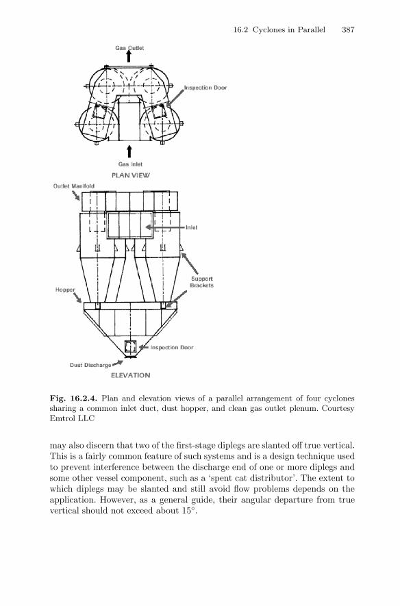
Fig. 16.2.4. Plan and elevation views of a parallel arrangement of four cyclonessharing a common inlet duct, dust hopper, and clean gas outlet plenum. CourtesyEmtrol LLC
may also discern that two of the first-stage diplegs are slanted off true vertical.This is a fairly common feature of such systems and is a design technique usedto prevent interference between the discharge end of one or more diplegs andsome other vessel component, such as a ‘spent cat distributor’. The extent towhich diplegs may be slanted and still avoid flow problems depends on theapplication. However, as a general guide, their angular departure from truevertical should not exceed about 15◦.
388 16 Multicyclone Arrangements
Fig. 16.2.5. A parallel arrangement of four cyclones sharing a common inlet ductand a common overhead and underflow plemum. Courtesy Ducon Technologies Inc.
Fig. 16.2.6. Plan view of four cyclones with a circular inlet distributor
Returning now to the much smaller sized cyclones comprising most multi-cyclone installations, one of their advantages over an external array of parallelcyclones is that the individual cyclones do not have to be equipped with theirown individual inlet pipes or ducts. A disadvantage is that, because the in-dividual cyclones are fully enclosed, it is not normally possible to performdiagnostic or repair work on the individual cyclones while they are in ser-vice. On the other hand, it is sometimes possible to repair or ‘patch up’ an
16.2 Cyclones in Parallel 389
1
23
Fig. 16.2.7. Vessel plan arrangement view of two parallel sets of three-stage cyclones
external cyclone that may be eroding or to unplug it with blasting jets, ifnecessary, while on-stream. In short, external cyclones are more accessible.Cyclones comprising a multicyclone installation are usually replaced whenthey become worn, whereas most other cyclones (such as those illustrated inthe figures below), are usually repaired, often in-place.
Because of their small size, some multicyclone installations experience op-erational problems as a result of plugging of their inlet ducts, bodies, or exitpipes. This can happen when dust agglomerates due to the presence of mois-ture, particularly when the temperature falls below the gas dew point. Plug-ging of cyclone bodies can occur if the hopper plugs and the dust level isallowed to rise to the level of the cyclones.
Pressure taps should be installed on multicyclone installations as an aidin determining how well they are performing. If the pressure drop across thesystem is less than their design value then there is a good chance that the dustcollection efficiency will be lower than it should be. There are several reasonswhy the pressure drop across a multicyclone can be lower than expected: First,the gas flow through the unit may be less than that for which it was designed.In this case, if the lower flow is expected to be the normal operating valuethen a portion of cyclones can be blocked off (in some symmetrical manner).Second, there may be holes in the upper tube sheet or in the collectors them-selves that allow the dust laden gas to bypass the collectors. Thirdly, the innerwalls of the individual cyclones may have become coated with deposits. Suchdeposits tend to increase the effective wall roughness which, in turn, decreasesthe spin, causing the pressure drop to decrease. The latter is especially trueIf the pressure drop is observed to be slowly decreasing over time (and whichcannot be explained on the basis of some change in operating conditions). The
390 16 Multicyclone Arrangements
presence of holes in the tube sheet or cyclone bodies, or deposit formations,can normally be verified only by inspection.
Fig. 16.2.8. A parallel set of 10 first-stage cyclones attached to the underside ofthe vessel head. Courtesy Fisher-Klosterman Inc.
Parallel arrangements of cyclones can be modelled using the same modelequations as for single units. The solids-bearing gas stream is simply dividedevenly between the parallel-working units. However, units working in parallelwill generally under-perform single, isolated units due to the problems asso-ciated with nonuniform gas (and sometimes, solids) distribution, as discussedin Chaps. 11 and 15.
There is no good way of estimating the difference in performance betweena single unit and the same unit working in parallel with others. Some workersclaim that this difference is significant. Our own experience is that units work-ing in parallel can perform almost as well as single units if uniform gas andsolids distribution is achieved in the inlet manifolding. One must be especiallyattentive of the inlet manifolding in configurations where the cyclones’ under-flow openings are free to communicate with one another. And, as indicatedback in Fig. 16.1.1, under no conditions should series-connected cyclones dis-
16.A Example Calculation for Multicyclone Arrangements 391
charge their solids into a common solids receiving vessel or hopper withoutproper isolation of their underflow pipes.
Fig. 16.2.9. A large 2-stage cyclone system typical of that used to collect catalystentrained off of the fluidized bed of a fluid catalytic cracking unit (FCCU). CourtesyEmtrol LLC
16.A Example Calculation for MulticycloneArrangements
Let us assume that the separation of the large cyclone in Appendix 5.A isinsufficient to meet emission standards. Specifically the loss from that cyclone
392 16 Multicyclone Arrangements
of1 300 mg/Nm3 has become unacceptable as we are faced with a new 70mg/Nm3 limit on emissions.
At the initial stage in the decision process, and before any measurementsare made, we wish to estimate on paper whether this target can be achievedusing cyclone technology, and if it can, what sort of cyclone arrangement mustbe installed downstream of the large cyclone.
Solution
The first step is to estimate the cut size needed to achieve the target emission.The required overall efficiency for the new cyclone stage is:
ηreq =(300 − 70)
300= 0.77.
If we know the size distribution of the solids lost from the large, first-stagecyclone we can determine the approximate cut size needed to achieve this.The strategy is as follows:
• Use the data from Appendix 5.A: the feed solids properties, the over-all efficiency, the grade-efficiency curve and Eq. (16.1.1) to calculate thedifferential size distribution of the overflow fraction from the first-stagecyclone.
• Convert this differential size distribution to a cumulative one• Use the method illustrated in Fig. 3.2.2 on this size distribution to convert
ηreq for the new cyclone installation to a required cut size.
Let us use the simple model of Barth for this first calculation. If we findthat cyclones are a feasible option, we can use more sophisticated calculationmodels, or scale experimental results for model cyclones later.
In Appendix 5.A we computed the first-stage cyclone’s cut size (6 µm),overall efficiency (90 %) and grade-efficiency curve by the method of Barth.As we have mentioned elsewhere, the experience of these authors is that mostcommercial cyclones separate with a somewhat shallower cut (lower exponentthan 6.4), but for this calculation, we use the Barth grade-efficiency curve.
We arrive at fe(x) by inserting the log-normal distribution (Eq. 2.B.6)with ln 〈x〉 = 3.32 and σ = 1.2 for ff (x), Eq. (5.2.2) with 6 µm for x50 forη(x), and 0.9 for η in Eq. (16.1.1).
Actually, it is possible to obtain an analytical expression for fe(x) in thisparticular case, but in most cases we need to split the x-axis up in a seriesof intervals, ∆xi, and then read or calculate values at the interval midpoints:ff (xi) and η(xi), and calculate points on the overhead size distribution: fe(xi)by Eq. (16.1.1).
1 mg/Nm3 = a milligram solids per normal cubic meter of gas. A normal cubicmeter is a cubic meter under conditions of normal temperature and pressure: 0◦Cand 1.013 bar.
16.A Example Calculation for Multicyclone Arrangements 393
The second step is to convert this differential size distribution to a cumu-lative one. This is straightforward. We use Eq. (2.3.3) or its finite equivalent:
F
(xi +
12∆xi
)=
i∑j=1
f (xj)∆xj
The resulting cumulative size distribution of the overhead solids from the largecyclone is shown in Fig. 16.A.1; the points on the distribution calculated bythe above procedure are connected with lines in the figure.
0
0.2
0.4
0.6
0.8
1.0
1 5 10 20
Particle size (µm)
Cum
ulat
ive
frac
tion
u/s
Fig. 16.A.1. Size distribution of the overhead solids from the large cyclone
Finally we use this size distribution to convert the required overall effi-ciency of 0.77 to a required cut size, using the method illustrated by Fig. 3.2.2.This process is shown in Fig. 16.A.1, and the required cut size can be seen tobe approximately 2.6 µm.
In regards to the cyclone’s cut size, we again utilize Eq. (5.2.1):
x50 =
√vrCS9µDx
ρpv2θCS
,
which, as mentioned, shows that the cyclone cut size x50 is proportional tothe square root of the diameter of the vortex finder, Dx. For a fixed cyclonegeometry, therefore, the cut size is proportional to the characteristic cyclonedimension, which we shall take to be the body diameter, D. Thus, the smallerthe cyclone, the smaller the cut diameter, so the more cyclones we split thetotal flow over, the smaller will be the cut size of the installation.
Knowing the required cut size, the second step is to determine what sortof cyclone installation would be required to achieve this. The strategy is now:
• Choose a standard cyclone geometry from Table 15.1.1
394 16 Multicyclone Arrangements
• Calculate the cut size as a function of the cyclone size• Choose the cyclone size giving the required cut size• Calculate the number of cyclones in parallel required to accomodate the
total flow
We choose a standard cyclone geometry from Table 15.1.1. The choicecan be indicated by considerations specific to the plant in question. In thisexample, we shall select the Lapple geometry, and a somewhat conservativeinlet velocity of 20 m/s.
To use Eq. (5.2.1), we need to calculate the velocities vrCS and vθCS
from Eqs. (4.2.4)–(4.2.6), following the procedure outlined in Appendix 5A.In doing this, we note that the velocities we calculate are only functions ofdimensional ratios2. In other words, for a constant inlet velocity the internalvelocities we calculate are independent of the scale of the cyclone.
Upon substituting the operational, physical and geometrical data in (4.5)-(4.7), along with values for vrCS and vθCS and Dx with (141/283) D (seeTable 15.1.1) in (5.2.1), we obtain the desired expression for the cut size. Thiscut size is observed to be a function of the cyclone diameter. Thus, for theLapple cyclone with an inlet velocity of 20 m/s we find:
x50 = 3.75 × 10⁻⁶√D. (16.A.1)
By repeating this exact same procedure for the first-stage cyclone we obtainthe result:
x50 = 3.00 × 10⁻⁶√D, (16.A.2)
which, for a 4 m diameter cyclone, gives a cut size of 6 µm. This is consistentwith our result in Chap. 5. The Lapple geometry is relatively longer than thefirst-stage cyclone, which makes it more efficient, but the lower inlet velocityand the relatively larger vortex finder makes for a larger cut size for a givenD.
From (16.A.1) we find that the value of D required to obtain a cut size of2.6 µm is 0.48 m. Moreover, using the data in Table 15.1.1, the inlet heightand width of such a cyclone are 0.24 m and 0.12 m, respectively.
With an inlet velocity of 20 m/s, the volumetric flow rate to each cy-clone becomes 0.24 × 0.12 × 20 = 0.576 m3/s. The total flow is (0.34×4) ×(0.24×4) × 30 = 39.2 m3/s, so we need 39.2/0.576 = 68 cyclones in parallelto accommodate the total flow.
This is a lot of cyclones and would very likely be deemed impractical froma cost point of view (including the cost of plot space!), not to mention theproblems one would encounter in trying to design a system this size and stillprovide uniform flow to each cyclone.
In a case like this, we would try to reduce the number of second-stagecyclones by increasing their inlet velocity and seeing if the resulting pressureloss is still acceptable. Increasing the inlet velocity allows us to increase the2 To see this more clearly substitute vinab for Q in Eq. (4.2.6).
16.A Example Calculation for Multicyclone Arrangements 395
size of the second-stage cyclones (higher inlet velocity – smaller cut size) andthis, in turn, increases their gas handling capacity. Thus, fewer cyclones arerequired to handle the flow. The price for this is an increase in pressure drop.Table 16.A.1 shows four possibilities in addition to our 68-unit, 20 m/s case.
Table 16.A.1. Four different inlet velocities to the second stage cyclones
Obviously, if pressure drops on the order of 6 to 8 kPa are acceptable froma process point of view, an 8 or 13-unit multicyclone (or some number in be-tween) could prove to be a viable option for the task at hand. If not, othertypes of separation equipment may have to be considered such as a baghouse,an electrostatic precipitator, or a wet scrubber. Nevertheless, even if the pres-sure drop across the cyclones were acceptable, one would still need to considerthe long-term wear implications associated with operating the cyclones at ve-locities in the range of 35 to 40 m/s. If the solids being processed are notespecially abrasive and/or if they are sufficiently fine in size, it may be pos-sible to operate at these velocities. If not, erosion-protective liners may needto be installed. Some bare-metal multicyclone systems have been observed tooperate for many years at velocities of 70 to 85 m/s while processing severaltons per day of rather abrasive sand-like particles that were under about 25µm in size.
Multicyclone installations which must exhibit a relatively low cut size (suchas that shown in the example above) are not normally suitable in processesthat can tolerate only a very limited amount of pressure drop across theseparator, such as 100 mm of water column, or less. If this is not a constraint,however, the fact that they operate dry and with no moving parts endowsthem with some distinct advantages over other separator types, such as wetscrubbers or bag houses. This is especially true if selling or using the productin dry form is advantageous to operations or if, for personnel protection orfrom a maintenance point of view, one does not wish to handle and maintainbag filters.