44
1 PETE 411 Well Drilling Lesson 17 Casing Design
| Date post: | 26-Dec-2015 |
| Category: |
Documents |
| Upload: | brahim-letaief |
| View: | 65 times |
| Download: | 20 times |
1
PETE 411Well Drilling
Lesson 17
Casing Design
2
Casing Design
◆ Why Run Casing?◆ Types of Casing Strings◆ Classification of Casing◆ Wellheads◆ Burst, Collapse and Tension◆ Example◆ Effect of Axial Tension on Collapse Strength◆ Example
3
Read Applied Drilling Engineering, Ch.7
HW #9 Due 10-18-02
4
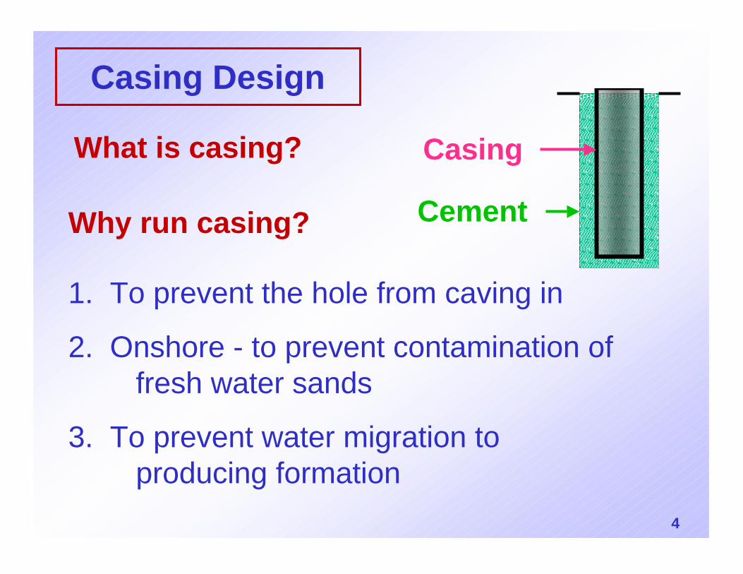
Casing Design
Why run casing?
1. To prevent the hole from caving in
2. Onshore - to prevent contamination of fresh water sands
3. To prevent water migration to producing formation
What is casing? Casing
Cement
5
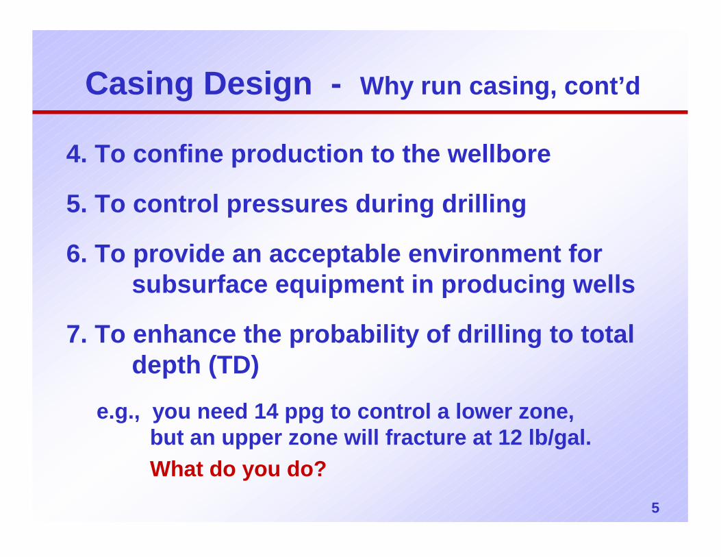
Casing Design - Why run casing, cont’d
4. To confine production to the wellbore
5. To control pressures during drilling
6. To provide an acceptable environment for subsurface equipment in producing wells
7. To enhance the probability of drilling to total depth (TD)
e.g., you need 14 ppg to control a lower zone, but an upper zone will fracture at 12 lb/gal.What do you do?
6
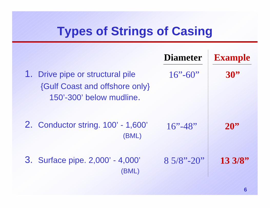
Types of Strings of Casing
1. Drive pipe or structural pile{Gulf Coast and offshore only}
150’-300’ below mudline.
2. Conductor string. 100’ - 1,600’(BML)
3. Surface pipe. 2,000’ - 4,000’(BML)
Diameter Example
16”-60” 30”
16”-48” 20”
8 5/8”-20” 13 3/8”
7
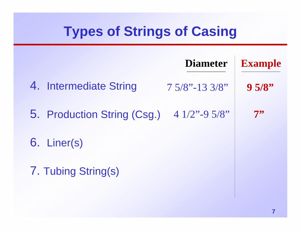
Types of Strings of Casing
4. Intermediate String
5. Production String (Csg.)
6. Liner(s)
7. Tubing String(s)
7 5/8”-13 3/8” 9 5/8”
Diameter Example
4 1/2”-9 5/8” 7”
8
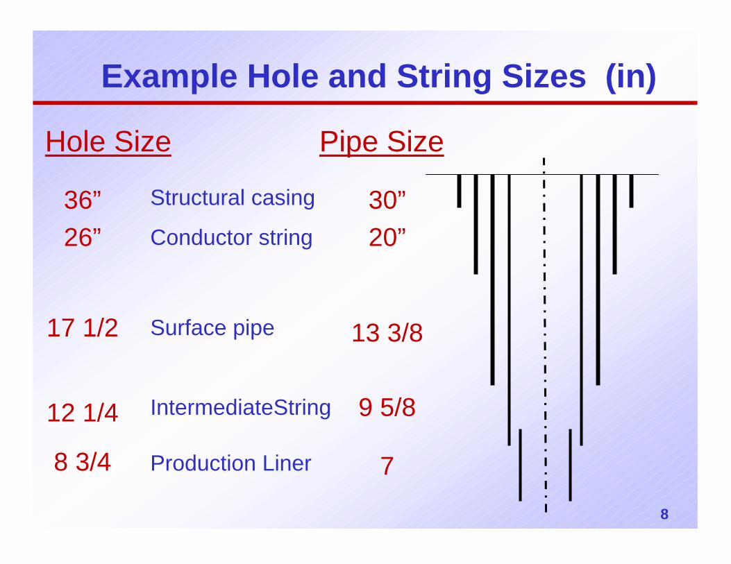
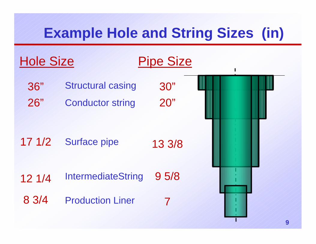
Example Hole and String Sizes (in)
Structural casing
Conductor string
Surface pipe
IntermediateString
Production Liner
Hole Size
30”20”
13 3/8
9 5/8
7
Pipe Size
36”26”
17 1/2
12 1/4
8 3/4
9
Example Hole and String Sizes (in)
Structural casing
Conductor string
Surface pipe
IntermediateString
Production Liner
Hole Size
30”20”
13 3/8
9 5/8
7
Pipe Size
36”26”
17 1/2
12 1/4
8 3/4
10
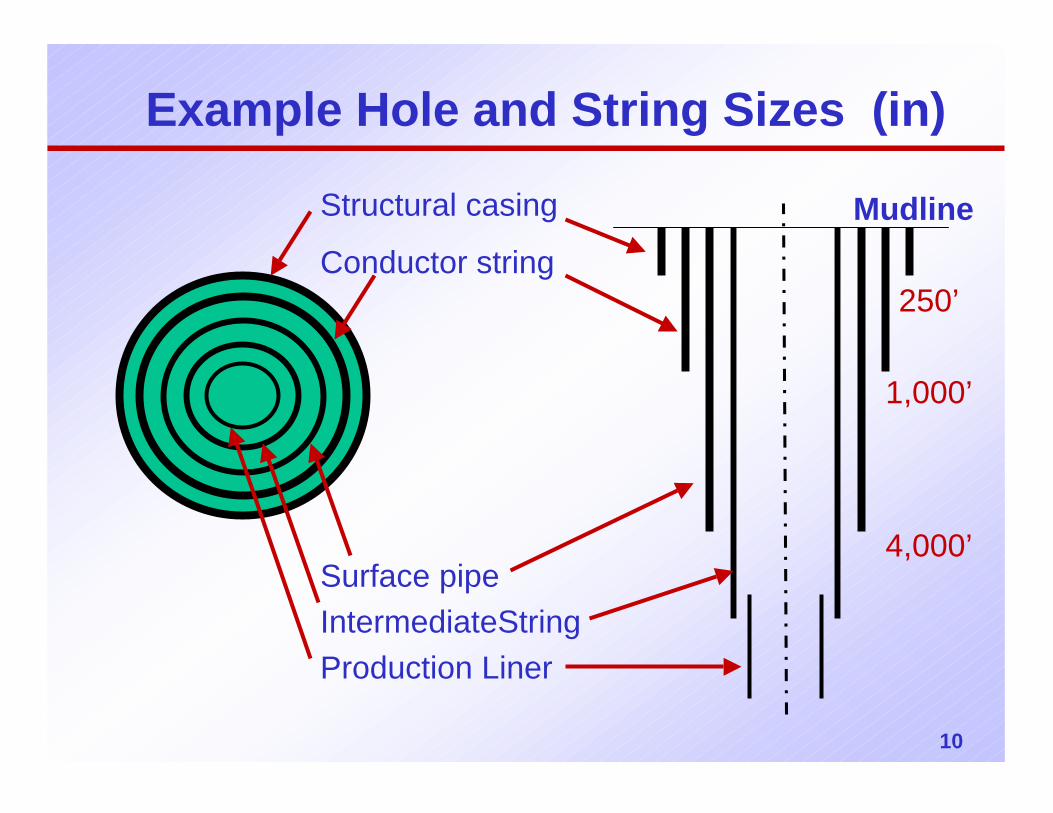
Example Hole and String Sizes (in)
Structural casing
Conductor string
Surface pipeIntermediateStringProduction Liner
250’
1,000’
4,000’
Mudline
11
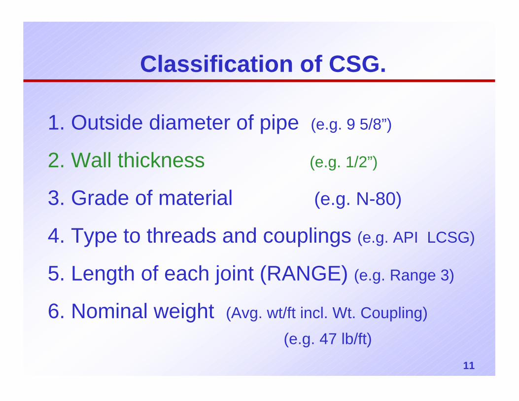
Classification of CSG.
1. Outside diameter of pipe (e.g. 9 5/8”)
2. Wall thickness (e.g. 1/2”)
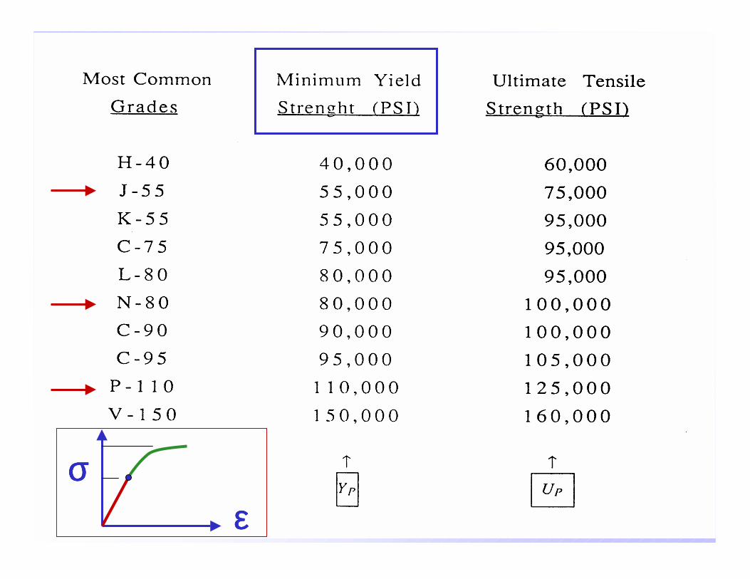
3. Grade of material (e.g. N-80)
4. Type to threads and couplings (e.g. API LCSG)
5. Length of each joint (RANGE) (e.g. Range 3)
6. Nominal weight (Avg. wt/ft incl. Wt. Coupling)(e.g. 47 lb/ft)
12
σσσσεεεε
13
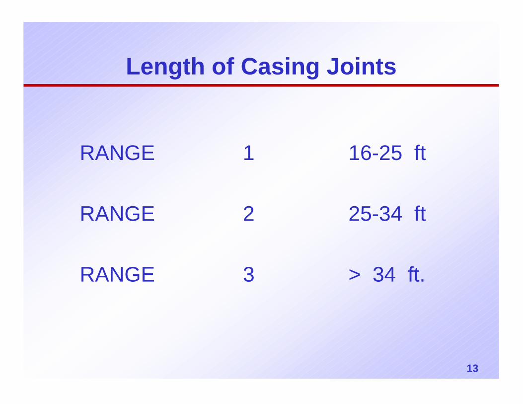
Length of Casing Joints
RANGE 1 16-25 ft
RANGE 2 25-34 ft
RANGE 3 > 34 ft.
14
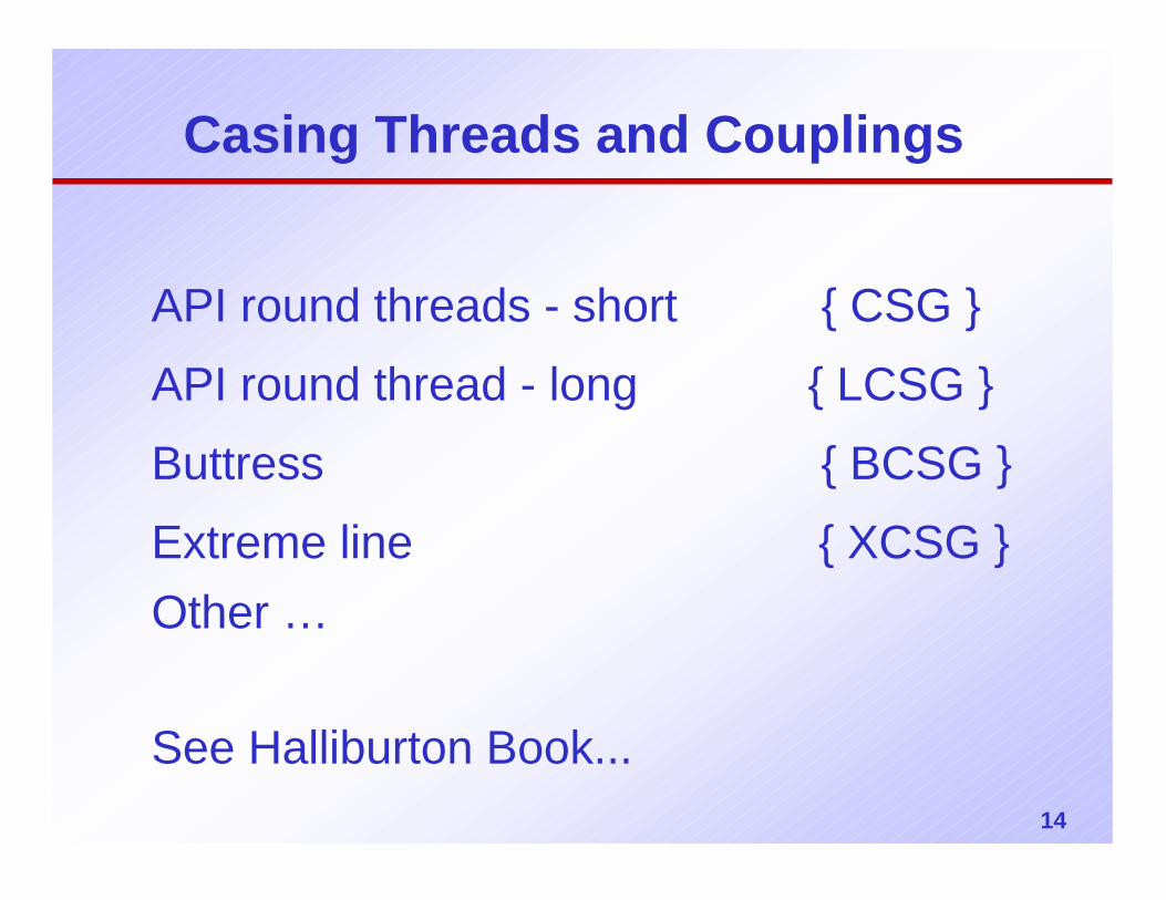
Casing Threads and Couplings
API round threads - short { CSG }
API round thread - long { LCSG }
Buttress { BCSG }
Extreme line { XCSG }Other …
See Halliburton Book...
15
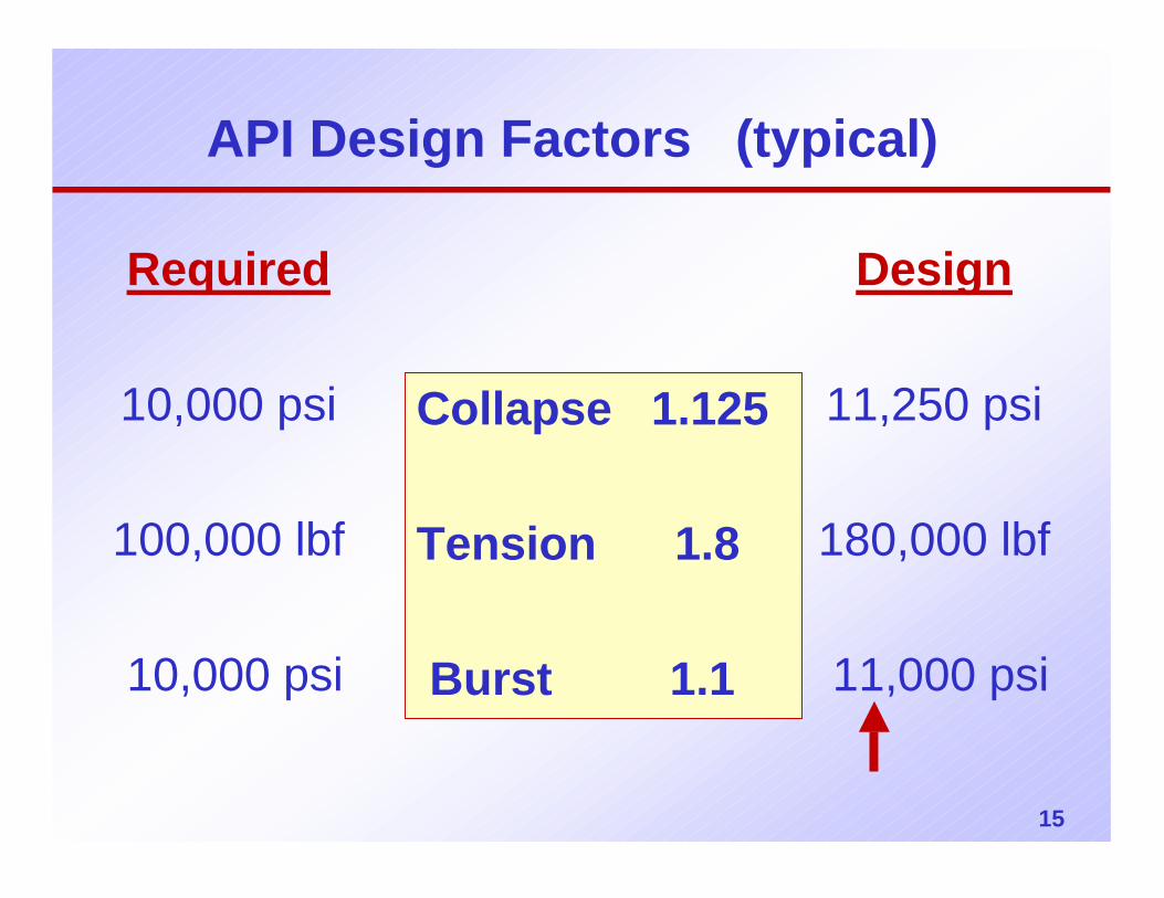
API Design Factors (typical)
Collapse 1.125
Tension 1.8
Burst 1.1
Required
10,000 psi
100,000 lbf
10,000 psi
Design
11,250 psi
180,000 lbf
11,000 psi
16
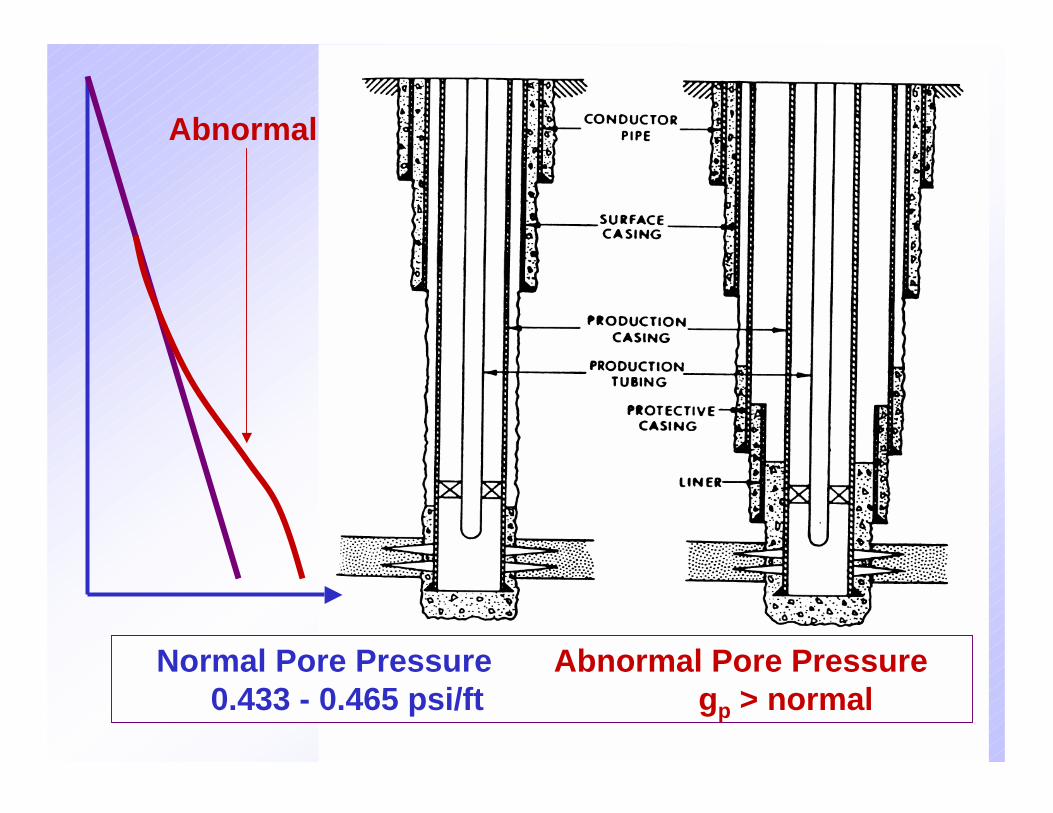
Normal Pore Pressure Abnormal Pore Pressure0.433 - 0.465 psi/ft gp > normal
Abnormal
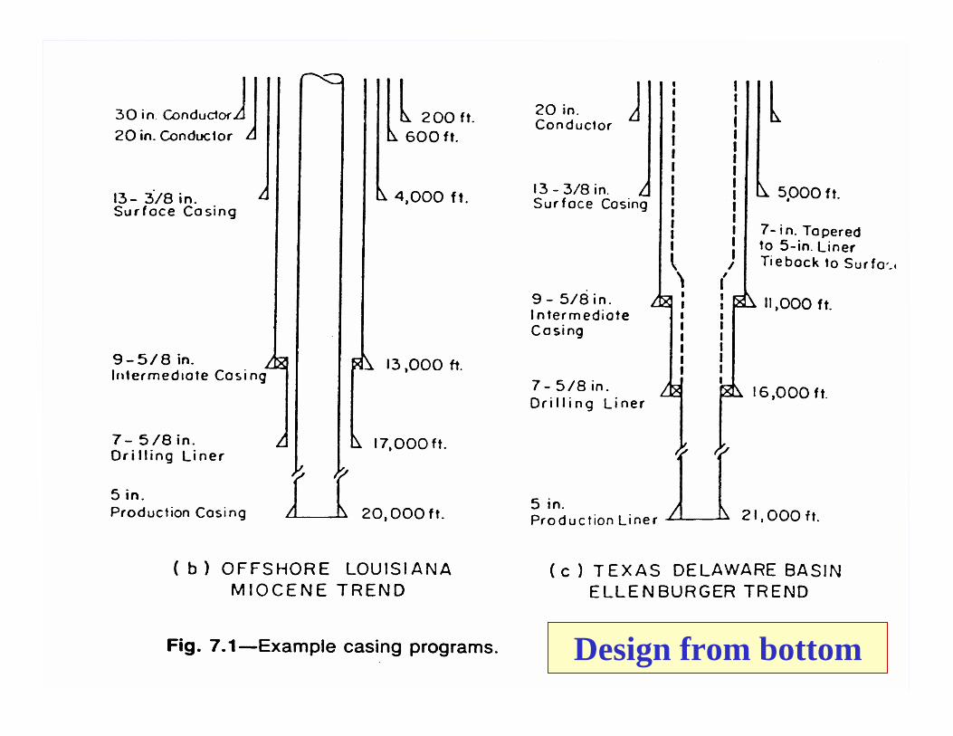
17Design from bottom
18
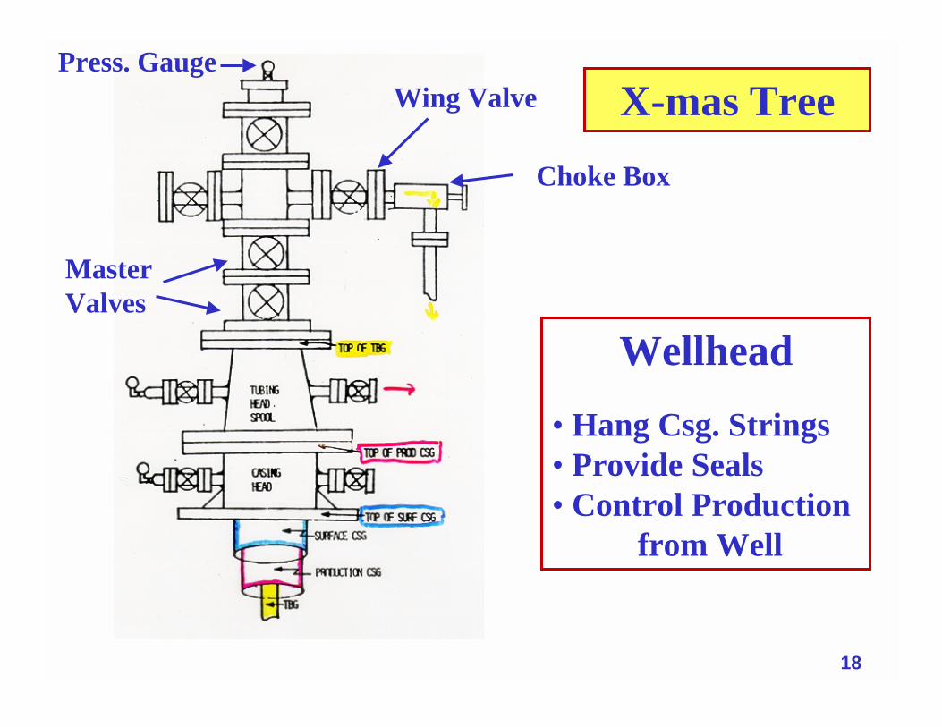
X-mas TreeWing Valve
Choke Box
MasterValves
Wellhead• Hang Csg. Strings• Provide Seals• Control Production
from Well
Press. Gauge
19
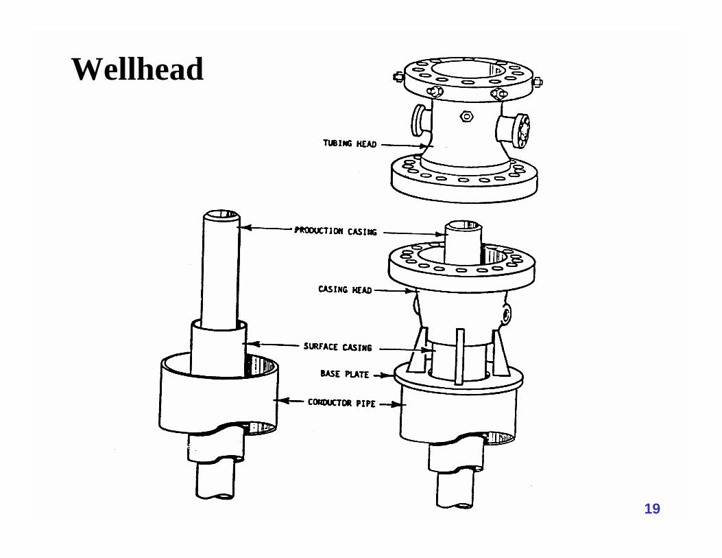
Wellhead
20
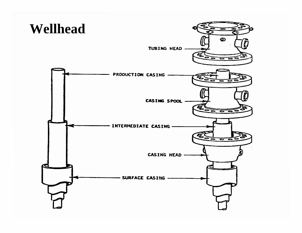
Wellhead
21
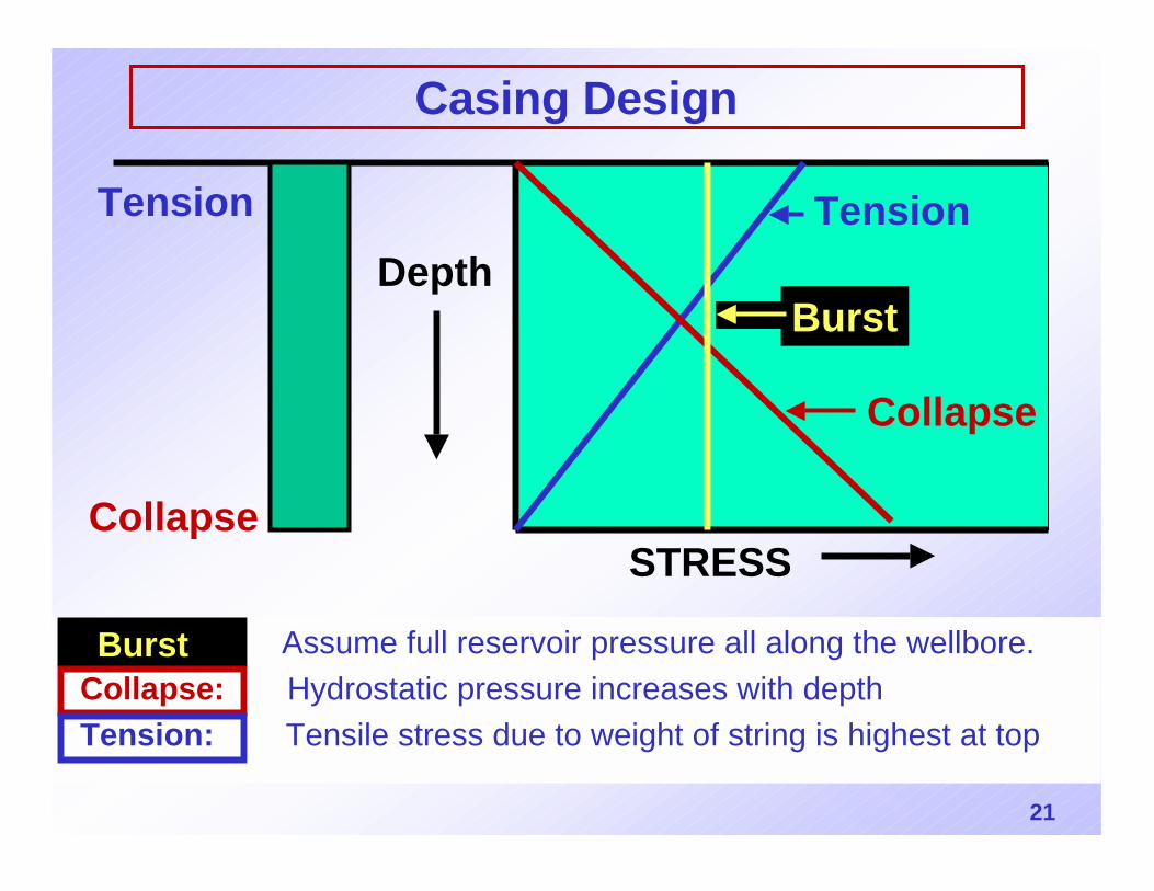
Casing Design
Burst: Assume full reservoir pressure all along the wellbore.Collapse: Hydrostatic pressure increases with depth Tension: Tensile stress due to weight of string is highest at top
STRESS
Tension
Burst
Collapse
Collapse
TensionDepth
Burst
22
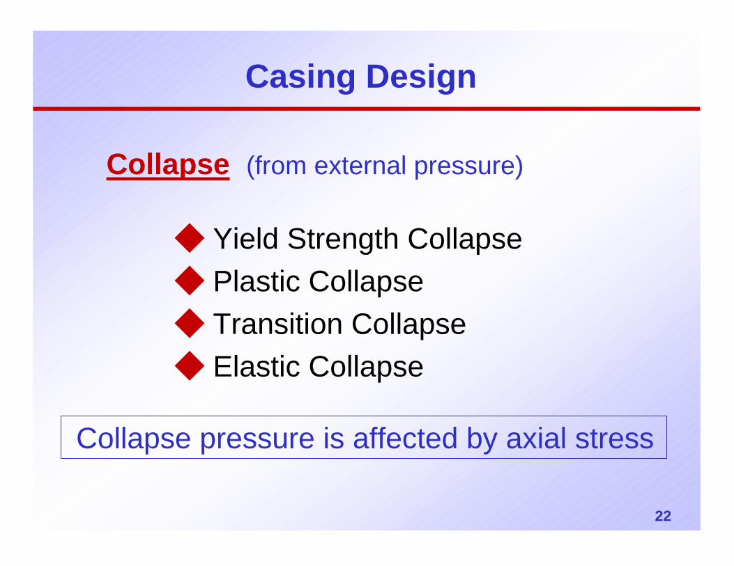
Casing Design
Collapse (from external pressure)
◆ Yield Strength Collapse◆ Plastic Collapse◆ Transition Collapse◆ Elastic Collapse
Collapse pressure is affected by axial stress
23
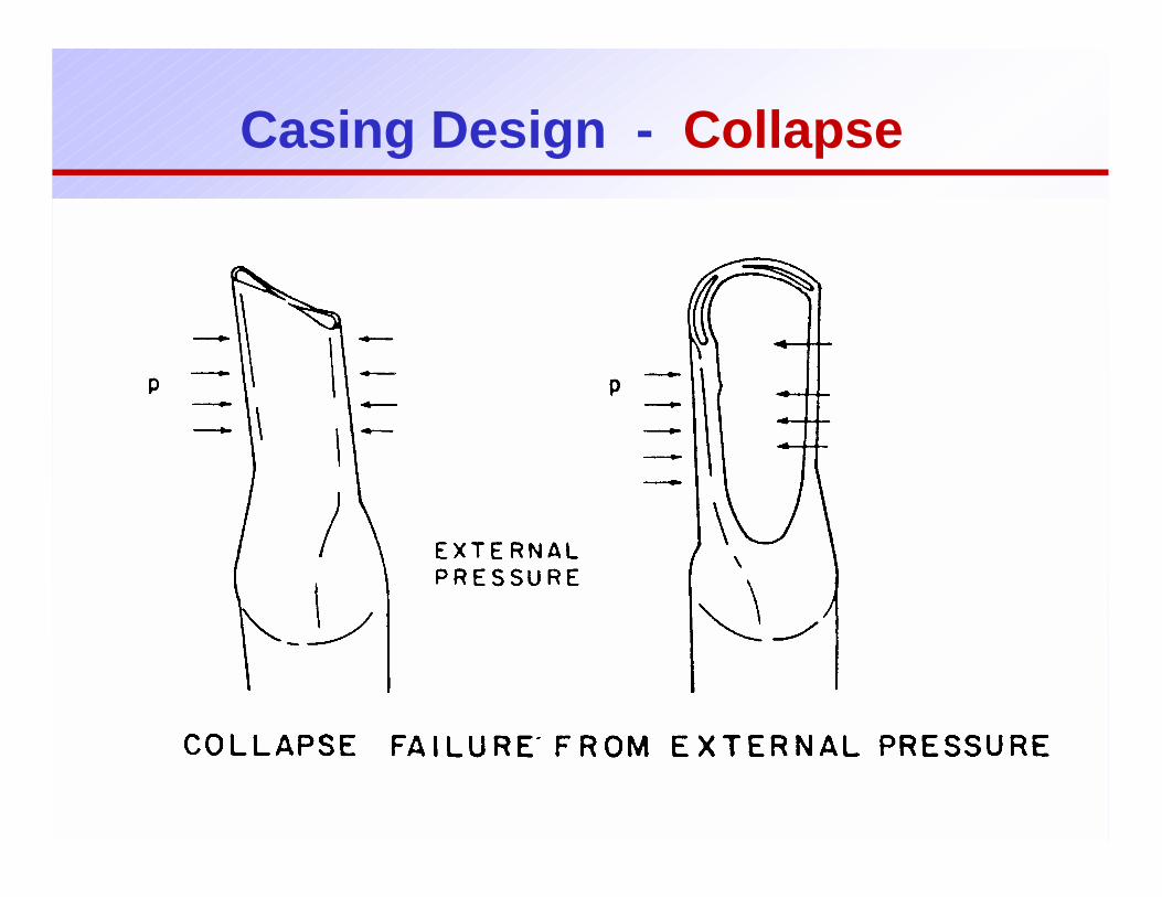
Casing Design - Collapse
24
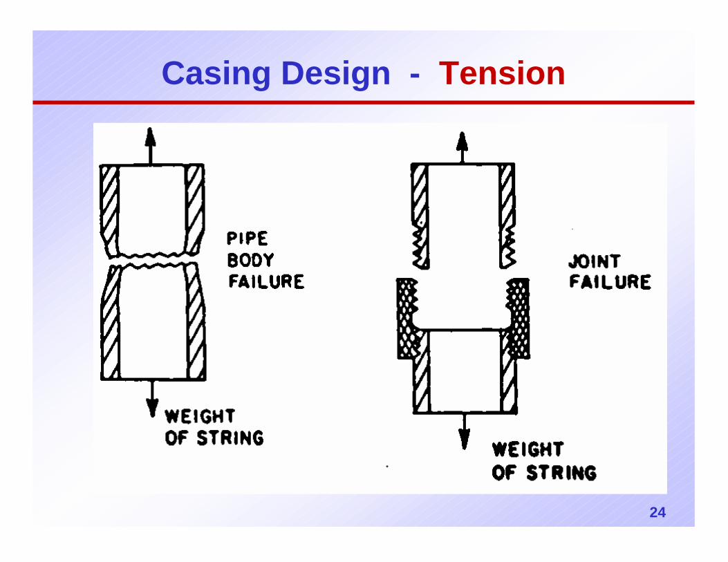
Casing Design - Tension
25
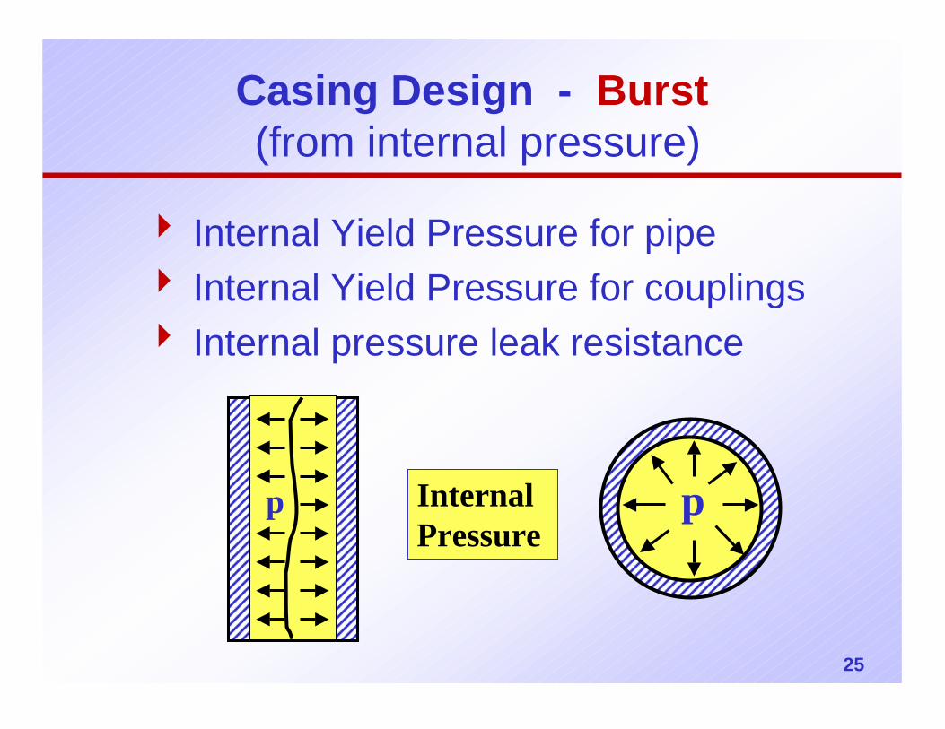
Casing Design - Burst(from internal pressure)
4 Internal Yield Pressure for pipe4 Internal Yield Pressure for couplings4 Internal pressure leak resistance
p pInternal Pressure
26
Casing Design - Burst
Example 1
Design a 7” Csg. String to 10,000 ft.
Pore pressure gradient = 0.5 psi/ftDesign factor, Ni=1.1
Design for burst only.
27
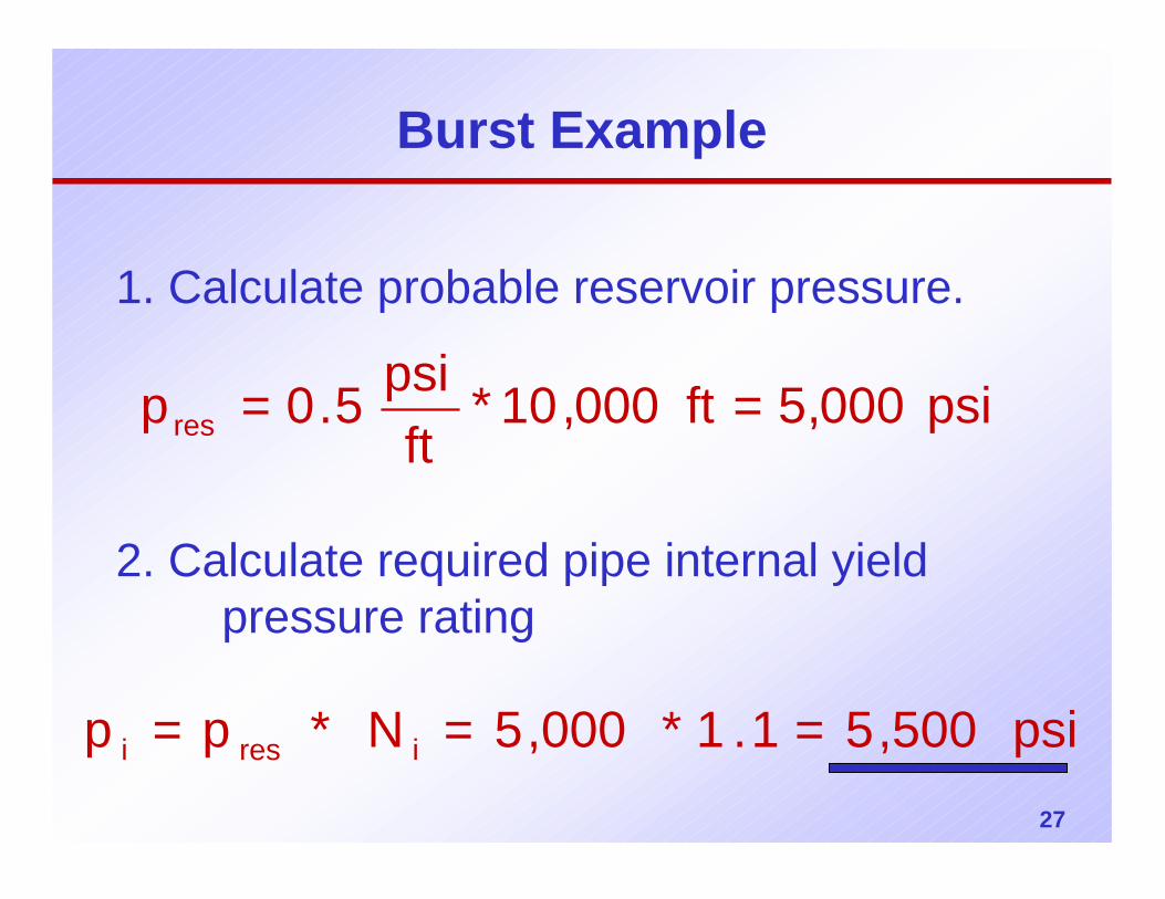
Burst Example
1. Calculate probable reservoir pressure.
psi 000,5 ft000,10*ft
psi5.0pres ==
2. Calculate required pipe internal yield pressure rating
psi 500,51.1 *000,5N *pp iresi ===
28
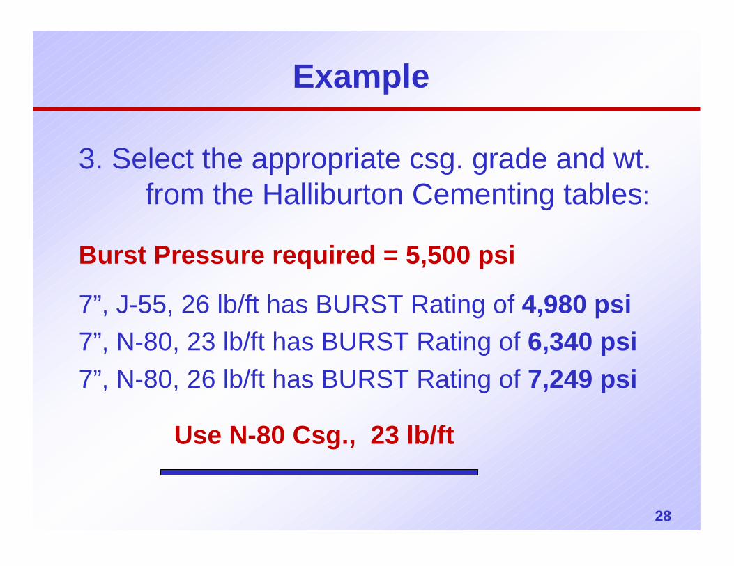
Example
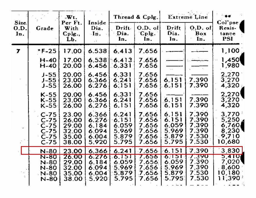
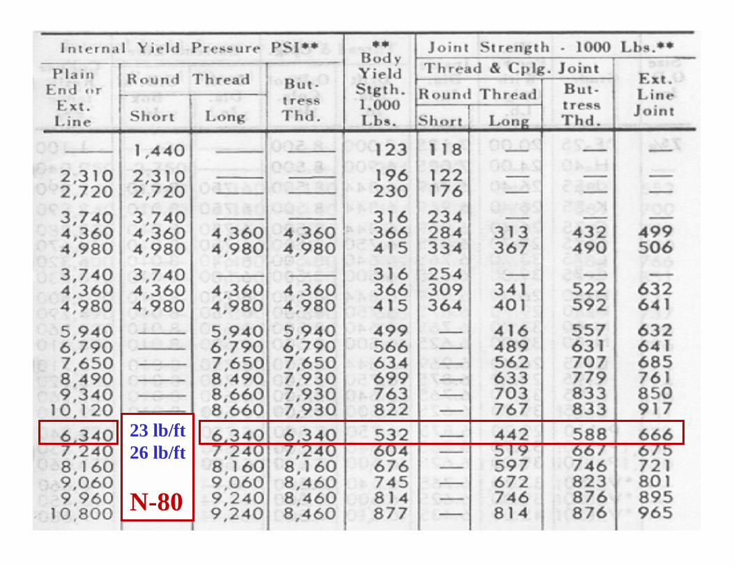
3. Select the appropriate csg. grade and wt. from the Halliburton Cementing tables:
Burst Pressure required = 5,500 psi
7”, J-55, 26 lb/ft has BURST Rating of 4,980 psi7”, N-80, 23 lb/ft has BURST Rating of 6,340 psi7”, N-80, 26 lb/ft has BURST Rating of 7,249 psi
Use N-80 Csg., 23 lb/ft
29
30
23 lb/ft26 lb/ft
N-80
31
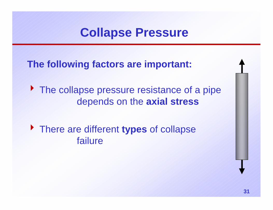
Collapse Pressure
The following factors are important:
4 The collapse pressure resistance of a pipe depends on the axial stress
4 There are different types of collapse failure
32
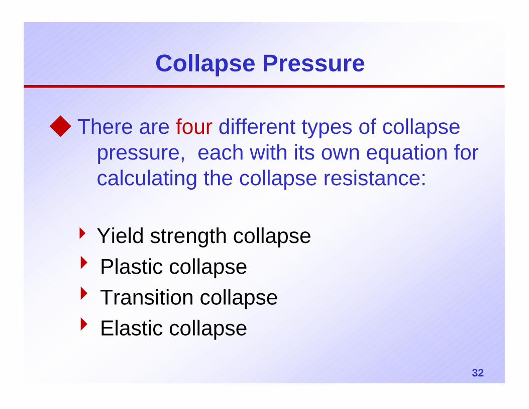
Collapse Pressure
◆ There are four different types of collapse pressure, each with its own equation for calculating the collapse resistance:
4 Yield strength collapse4 Plastic collapse4 Transition collapse4 Elastic collapse
33
Casing Design
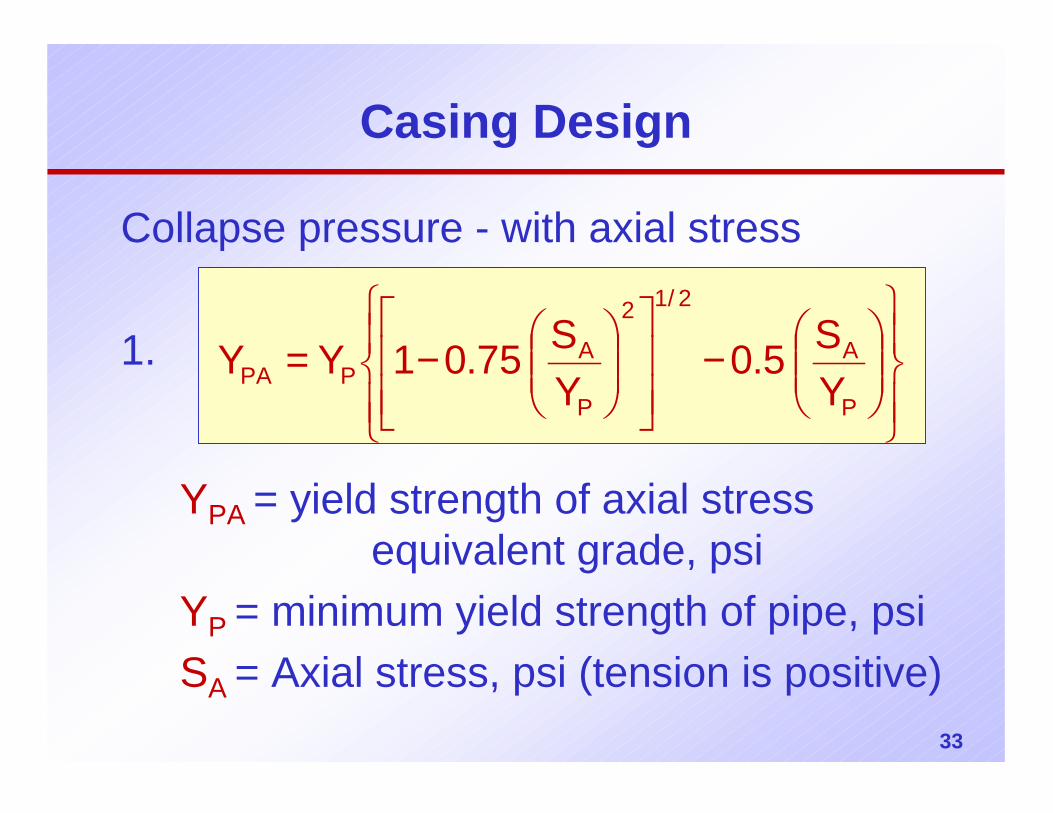
Collapse pressure - with axial stress
1.
−
−=
P
A
2/12
P
APPA Y
S5.0YS75.01YY
YPA = yield strength of axial stress equivalent grade, psi
YP = minimum yield strength of pipe, psiSA = Axial stress, psi (tension is positive)
34
Casing Design - Collapse
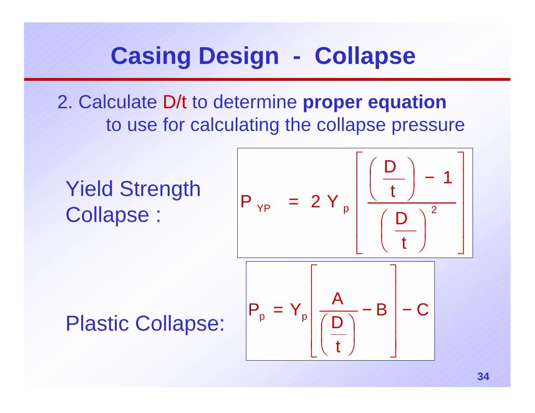
2. Calculate D/t to determine proper equationto use for calculating the collapse pressure
Yield Strength Collapse :
Plastic Collapse:
−
= 2pYP
tD
1t
D
Y2P
CB
tDAYP pp −
−
=
35
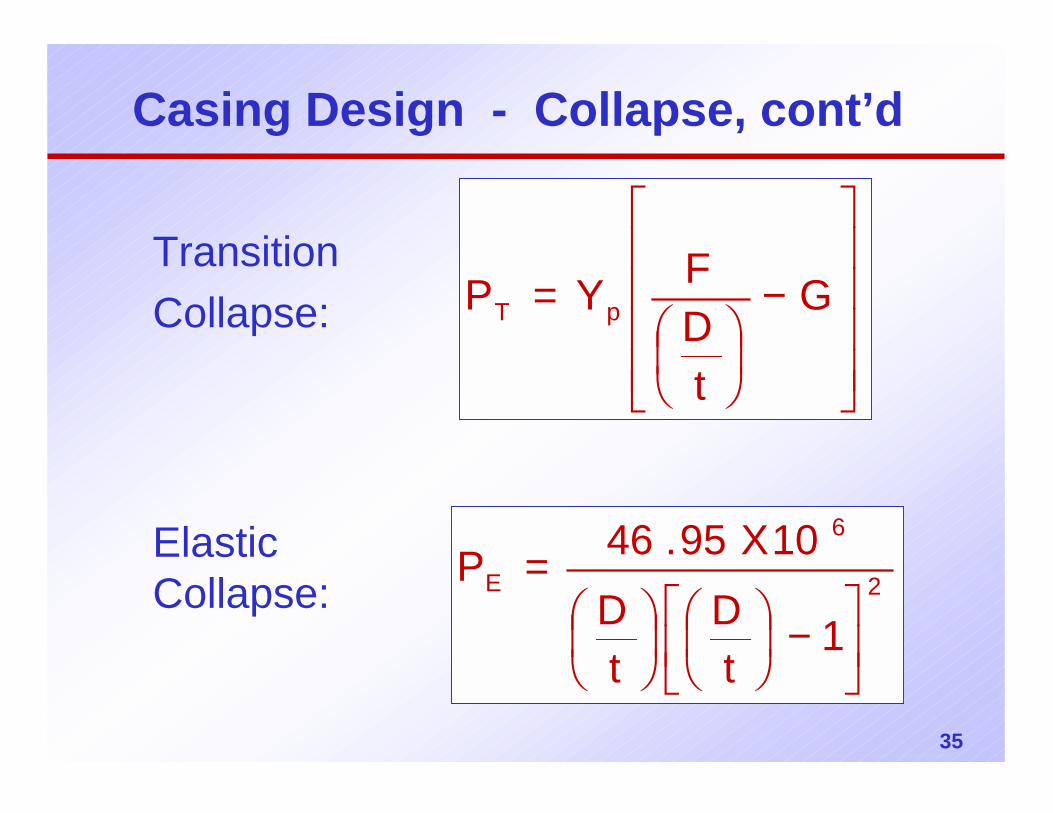
Transition Collapse:
Elastic Collapse:
−
= G
tDFYP pT
2
6
E
1t
Dt
D
10X95.46P
−
=
Casing Design - Collapse, cont’d
36
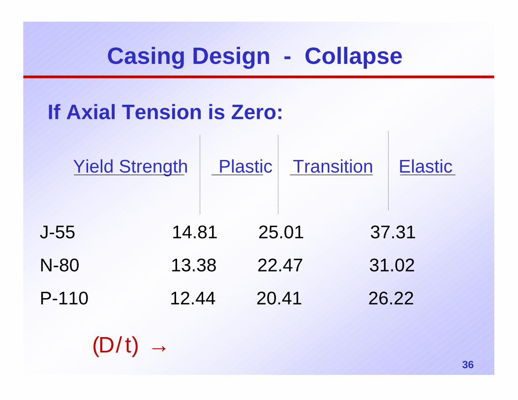
If Axial Tension is Zero:
Yield Strength Plastic Transition Elastic
→ )t/D(
J-55 14.81 25.01 37.31
N-80 13.38 22.47 31.02
P-110 12.44 20.41 26.22
Casing Design - Collapse
37
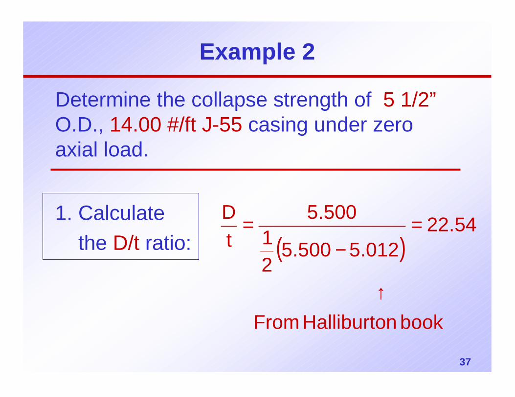
Example 2
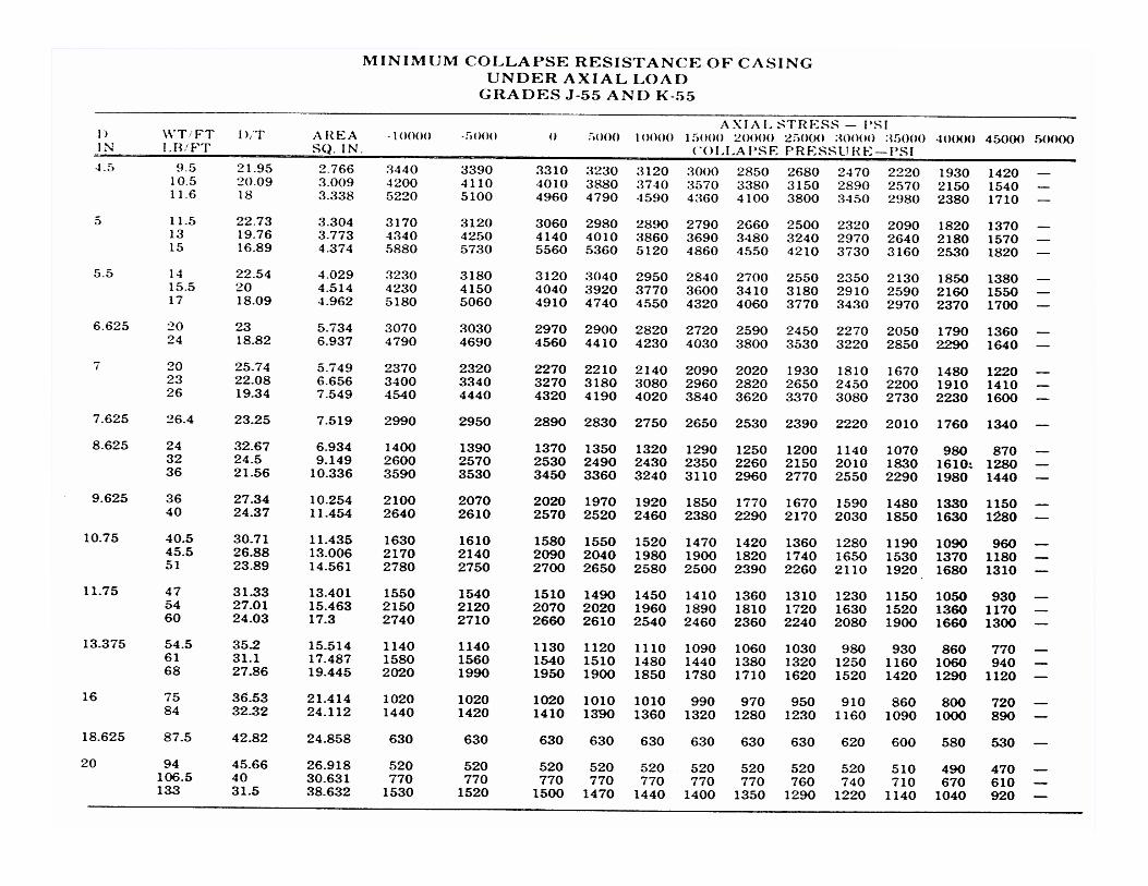
Determine the collapse strength of 5 1/2”O.D., 14.00 #/ft J-55 casing under zero axial load.
1. Calculatethe D/t ratio: ( )
book nHalliburto From
54.22012.5500.5
21
500.5tD
↑
=−
=
38
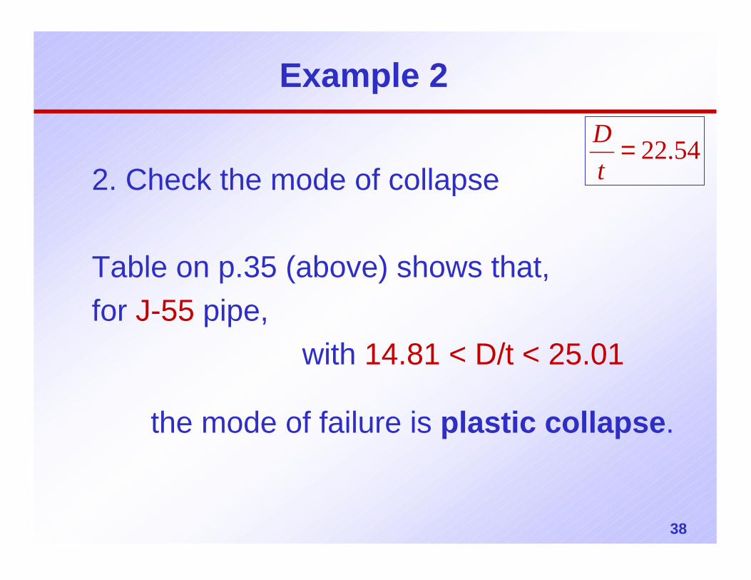
Example 2
2. Check the mode of collapse
Table on p.35 (above) shows that, for J-55 pipe,
with 14.81 < D/t < 25.01
the mode of failure is plastic collapse.
54.22=tD
39
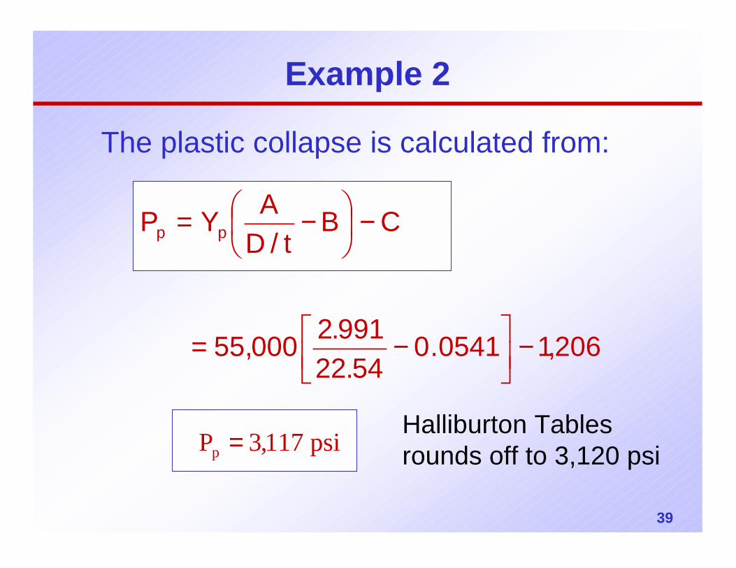
Example 2
The plastic collapse is calculated from:
206,10541.054.22
991.2000,55
CBt/D
AYP pp
−
−=
−
−=
psi117,3Pp =Halliburton Tables rounds off to 3,120 psi
40
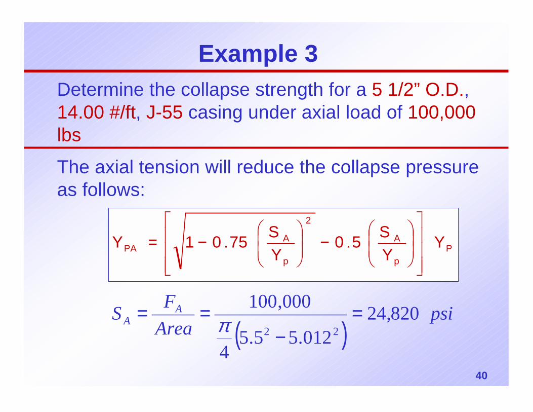
Example 3Determine the collapse strength for a 5 1/2” O.D., 14.00 #/ft, J-55 casing under axial load of 100,000 lbs
The axial tension will reduce the collapse pressure as follows:
Pp
A
2
p
APA Y
YS5.0
YS75.01Y
−
−=
( )psi
AreaFS A
A 820,24012.55.5
4
000,10022
=−
== π
41
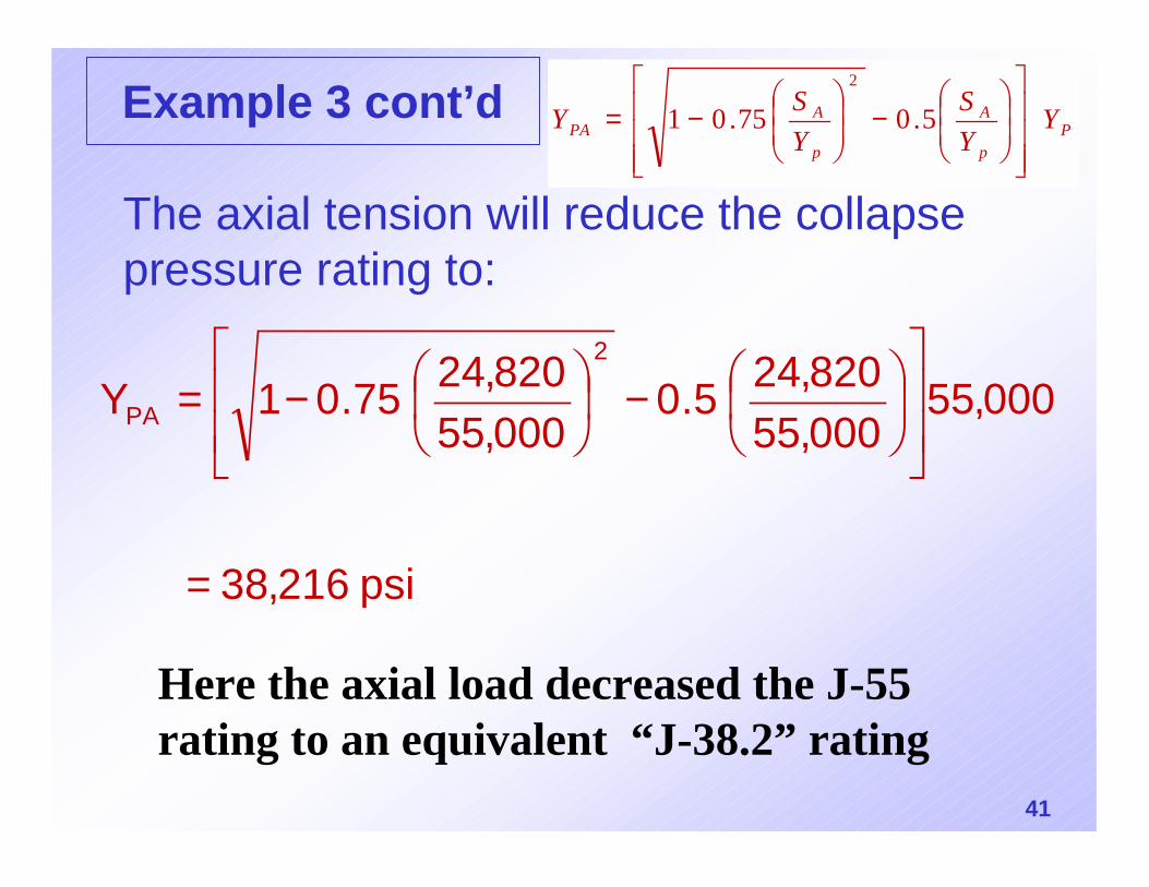
Example 3 cont’d
The axial tension will reduce the collapse pressure rating to:
psi 216,38
000,55000,55820,245.0
000,55820,2475.01Y
2
PA
=
−
−=
Here the axial load decreased the J-55 rating to an equivalent “J-38.2” rating
Pp
A
p
APA Y
YS
YSY
−
−= 5.075.01
2
42
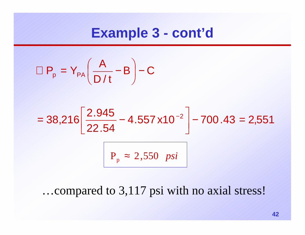
Example 3 - cont’d
551,243.70010x557.454.22
945.2216,38
CBt/D
AYP
2
PAp
=−
−=
−
−=∴
−
psi 550,2Pp ≈
…compared to 3,117 psi with no axial stress!
43
44


