103
1 MASTER Well Drilling Casi ng Desi gn
| Date post: | 14-Apr-2018 |
| Category: |
Documents |
| Upload: | zhong-ying |
| View: | 222 times |
| Download: | 3 times |
7/30/2019 4 Casing Design
http://slidepdf.com/reader/full/4-casing-design 1/103
1
MASTER
Well Drill ing
Casing Design

7/30/2019 4 Casing Design
http://slidepdf.com/reader/full/4-casing-design 2/103
2
Casing Design
Why Run Casing?
Types of Casing Strings
Classification of Casing
Wellheads Burst, Collapse and Tension
Example
Effect of Axial Tension on Collapse Strength
Example

7/30/2019 4 Casing Design
http://slidepdf.com/reader/full/4-casing-design 3/103
3
Read Applied Drilling Engineering, Ch.7

7/30/2019 4 Casing Design
http://slidepdf.com/reader/full/4-casing-design 4/103
4
Casing Design
Why run casing?
1. To prevent the hole from caving in2. Onshore - to prevent contamination of
fresh water sands
3. To prevent water migration toproducing formation
What is casing? Casing
Cement

7/30/2019 4 Casing Design
http://slidepdf.com/reader/full/4-casing-design 5/103
5
Casing Design - Why run casing, cont’d
4. To confine production to the wellbore
5. To control pressures during drill ing
6. To provide an acceptable environment for
subsurface equipment in producing wells
7. To enhance the probability of drilling to total
depth (TD)
e.g., you need 14 ppg to control a lower zone,
but an upper zone will fracture at 12 lb/gal.
What do you do?
7/30/2019 4 Casing Design
http://slidepdf.com/reader/full/4-casing-design 6/103
6
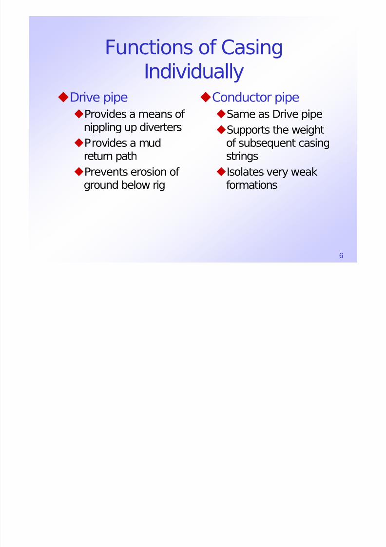
Functions of CasingIndividually
Drive pipeProvides a means of
nippling up diverters
Provides a mudreturn path
Prevents erosion of ground below rig
Conductor pipeSame as Drive pipe
Supports the weight
of subsequent casingstrings
Isolates very weakformations

7/30/2019 4 Casing Design
http://slidepdf.com/reader/full/4-casing-design 7/103
7
Functions of Casing
IndividuallySurface casing
Provides a means of
nippling up BOPProvides a casing
seat strong enoughto safely close in a
well after a kick.Provides protection
of fresh water sands
Provides wellborestabilization
Intermediate orprotective casing
Usually set in thefirst abnormallypressured zone
Provides isolation of
potentiallytroublesome zones
Provides integrity to
withstand the highmud weightsnecessary to reach TD or next csg seat

7/30/2019 4 Casing Design
http://slidepdf.com/reader/full/4-casing-design 8/103
8
Functions of Casing IndividuallyProduction casing
Provides zonalisolation (prevents
migration of water toproducing zones,isolates differentproduction zones)
Confines productionto wellbore
Provides the
environment to installsubsurfacecompletionequipment
Liners
Drilling liners
Same as
Intermediate orprotective casing
Production liners
Same as production
casing
Tieback liners
Tie back drilling orproduction liner to the
surface. Convertsliner to full string of casing

7/30/2019 4 Casing Design
http://slidepdf.com/reader/full/4-casing-design 9/103
9
Types of Strings of Casing
1. Drive pipe or structural pile{Gulf Coast and offshore only}
150’-300’ below mudline.
2. Conductor string. 100’ - 1,600’
(BML)
3. Surface pipe. 2,000’ - 4,000’
(BML)
Diameter Example
16”-60” 30”
16”-48” 20”
8 5/8”-20” 13 3/8”

7/30/2019 4 Casing Design
http://slidepdf.com/reader/full/4-casing-design 10/103
10
Types of Strings of Casing
4. Intermediate String
5. Production String (Csg.)
6. Liner(s)
7. Tubing String(s)
7 5/8”-13 3/8” 9 5/8”
Diameter Example
4 1/2”-9 5/8” 7”

7/30/2019 4 Casing Design
http://slidepdf.com/reader/full/4-casing-design 11/103
11
Example Hole and String Sizes (in)
Structural casing
Conductor string
Surface pipe
IntermediateString
Production Liner
Hole Size
30”20”
13 3/8
9 5/8
7
Pipe Size
36”26”
17 1/2
12 1/4
8 3/4

7/30/2019 4 Casing Design
http://slidepdf.com/reader/full/4-casing-design 12/103
12
Example Hole and String Sizes (in)
Structural casing
Conductor string
Surface pipe
IntermediateString
Production Liner
Hole Size
30”20”
13 3/8
9 5/8
7
Pipe Size
36”26”
17 1/2
12 1/4
8 3/4

7/30/2019 4 Casing Design
http://slidepdf.com/reader/full/4-casing-design 13/103
13
Example Hole and String Sizes (in)
Structural casing
Conductor string
Surface pipeIntermediateString
Production Liner
250’
1,000’
4,000’
Mudline

7/30/2019 4 Casing Design
http://slidepdf.com/reader/full/4-casing-design 14/103
14
Classification of CSG.
1. Outside diameter of pipe (e.g. 9 5/8”)
2. Wall thickness (e.g. 1/2”)
3. Grade of material (e.g. N-80)
4. Type to threads and couplings (e.g. API LCSG)
5. Length of each joint (RANGE) (e.g. Range 3)
6. Nominal weight (Avg. wt/ft incl. Wt. Coupling)
(e.g. 47 lb/ft)

7/30/2019 4 Casing Design
http://slidepdf.com/reader/full/4-casing-design 15/103
15
σ
ε

7/30/2019 4 Casing Design
http://slidepdf.com/reader/full/4-casing-design 16/103
16
Length of Casing Joints
RANGE 1 16-25 ft
RANGE 2 25-34 ft
RANGE 3 > 34 ft.

7/30/2019 4 Casing Design
http://slidepdf.com/reader/full/4-casing-design 17/103
17
Casing Threads and Couplings
API round threads - short {CSG }API round thread - long {LCSG }
Buttress {BCSG }Extreme line {XCSG }
Other …
See Halliburton Book...

7/30/2019 4 Casing Design
http://slidepdf.com/reader/full/4-casing-design 18/103
18
Rounded Threads
* 8 per inch
~ Square Threads
* Longer* Stronger
Integral Joint
* Smaller ID, OD
* Costs more
* Strong

7/30/2019 4 Casing Design
http://slidepdf.com/reader/full/4-casing-design 19/103
19

7/30/2019 4 Casing Design
http://slidepdf.com/reader/full/4-casing-design 20/103
20
23 lb/ft
26 lb/ft
N-80

7/30/2019 4 Casing Design
http://slidepdf.com/reader/full/4-casing-design 21/103
21
API Design Factors (typical)
Collapse 1.125
Tension 1.8
Burst 1.1
Required
10,000 psi
100,000 lbf
10,000 psi
Design
11,250 psi
180,000 lbf
11,000 psi

7/30/2019 4 Casing Design
http://slidepdf.com/reader/full/4-casing-design 22/103
22
Normal Pore Pressure Abnormal Pore Pressure
0.433 - 0.465 psi/ft gp
> normal
Abnormal

7/30/2019 4 Casing Design
http://slidepdf.com/reader/full/4-casing-design 23/103
23Design from bottom

7/30/2019 4 Casing Design
http://slidepdf.com/reader/full/4-casing-design 24/103
24
X-mas TreeWing Valve
Choke Box
Master
Valves
Wellhead
• Hang Csg. Strings
• Provide Seals
• Control Productionfrom Well
Press. Gauge

7/30/2019 4 Casing Design
http://slidepdf.com/reader/full/4-casing-design 25/103
25
Wellhead

7/30/2019 4 Casing Design
http://slidepdf.com/reader/full/4-casing-design 26/103
26
Wellhead
7/30/2019 4 Casing Design
http://slidepdf.com/reader/full/4-casing-design 27/103
27
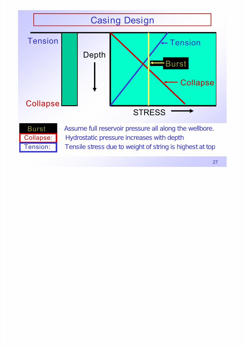
Casing Design
Burst: Assume full reservoir pressure all along the wellbore.
Collapse: Hydrostatic pressure increases with depth
Tension: Tensile stress due to weight of string is highest at top
STRESS
Tension
Burst
Collapse
Collapse
Tension
Depth
Burst

7/30/2019 4 Casing Design
http://slidepdf.com/reader/full/4-casing-design 28/103
28
Casing Design - Tension

7/30/2019 4 Casing Design
http://slidepdf.com/reader/full/4-casing-design 29/103
29
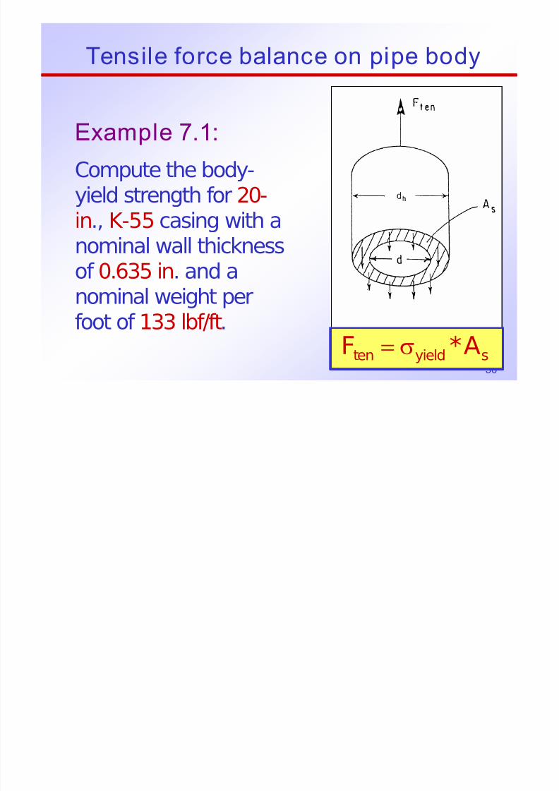
Tensile force balance on pipe body
A*Fsyieldten
σ=
7/30/2019 4 Casing Design
http://slidepdf.com/reader/full/4-casing-design 30/103
30
Tensile force balance on pipe body
Example 7.1:
Compute the body-yield strength for 20-
in., K-55 casing with anominal wall thicknessof 0.635 in. and a
nominal weight perfoot of 133 lbf/ft.
A*Fsyieldten
σ=

7/30/2019 4 Casing Design
http://slidepdf.com/reader/full/4-casing-design 31/103
31
Tensile force balance on pipe body
Solution: This pipe has a minimum
yield strength of 55,000 psiand an ID of:
.in730.18)635.0(200.20d =−=
K55
A*F syieldten σ=

7/30/2019 4 Casing Design
http://slidepdf.com/reader/full/4-casing-design 32/103
32
Tensile force balance on pipe body
Thus, the cross-sectional area of steel is
and a minimum pipe-body yield
is predicted by Eq. 7.1 atan axial force of:
.in.sq 63.38)73.1820(4
A 22s =−=
π
lbf 000,125,2)63.38(000,55Ften ==
A*F syieldten σ=

7/30/2019 4 Casing Design
http://slidepdf.com/reader/full/4-casing-design 33/103
33
Pipe Body Yield Strength
where
p
22
y Y)dD(4P −=
inpipe,of diameter insided
inpipe,of diameter outsideD
psistrength,yieldminimumspecifiedY
lbf strength,yieldbodypipeP
p
y
=
=
=
=
7/30/2019 4 Casing Design
http://slidepdf.com/reader/full/4-casing-design 34/103
34
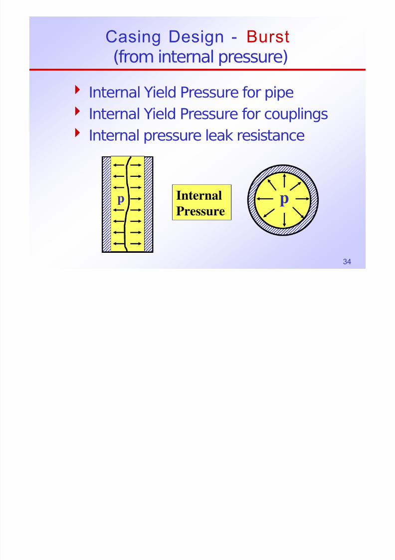
Casing Design - Burst
(from internal pressure)
4 Internal Yield Pressure for pipe
4 Internal Yield Pressure for couplings
4 Internal pressure leak resistance
pp
Internal
Pressure

7/30/2019 4 Casing Design
http://slidepdf.com/reader/full/4-casing-design 35/103
35
Internal Yield Pressure for Pipe (Burst)
where
⎥⎦
⎤
⎢⎣
⎡
= D
t Y2
875.0Pp
inpipe,of O.D.D
inthickness,wallnominalt
psistrength,yieldminimumY
psipressure,yieldinternalP
p
=
=
=
=
FP = DLP
F T = 2tLYP
DLP = 2tLYP
⎥⎦
⎤⎢⎣
⎡=
D
t2YP
p
FP
FT

7/30/2019 4 Casing Design
http://slidepdf.com/reader/full/4-casing-design 36/103
36
Example
For 7”, 26 #/ft P-110 pipe
9,955
7*26.276)-(7*110,000*2*0.875
=
=
psi960,9P = (to the nearest 10 psi)
…agrees with Halliburton Tables.
⎥⎦
⎤⎢⎣
⎡=
D
tY2875.0P
p

7/30/2019 4 Casing Design
http://slidepdf.com/reader/full/4-casing-design 37/103
37
Casing Design - Burst
Example
Design a 7” Csg. String to 10,000 ft.
Pore pressure gradient = 0.5 psi/ft
Design factor, Ni=1.1
Design for burst only.

7/30/2019 4 Casing Design
http://slidepdf.com/reader/full/4-casing-design 38/103
38
Burst Example
1. Calculate probable reservoir pressure.
psi000,5ft000,10*ft
psi5.0pres ==
2. Calculate required pipe internal yieldpressure rating
psi500,51.1*000,5N*pp iresi ===
Ni = API Design Factor for BURST = 1.1

7/30/2019 4 Casing Design
http://slidepdf.com/reader/full/4-casing-design 39/103
39
Example
3. Select the appropriate csg. grade and wt.
from the Halliburton Cementing tables:
Burst Pressure required = 5,500 psi
7”, J -55, 26 lb/ft has BURST Rating of 4,980 psi7”, N-80, 23 lb/ft has BURST Rating of 6,340 psi
7”, N-80, 26 lb/ft has BURST Rating of 7,249 psi
Use N-80 Csg., 23 lb/ft

7/30/2019 4 Casing Design
http://slidepdf.com/reader/full/4-casing-design 40/103
40

7/30/2019 4 Casing Design
http://slidepdf.com/reader/full/4-casing-design 41/103
41
23 lb/ft
26 lb/ft
N-80
7/30/2019 4 Casing Design
http://slidepdf.com/reader/full/4-casing-design 42/103
42
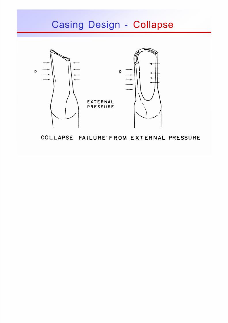
Casing Design - Collapse

7/30/2019 4 Casing Design
http://slidepdf.com/reader/full/4-casing-design 43/103
43
Collapse Pressure
The following factors are important:
4 The collapse pressure resistance of a pipedepends on the axial stress
4 There are different types of collapsefailure

7/30/2019 4 Casing Design
http://slidepdf.com/reader/full/4-casing-design 44/103
44
Collapse Pressure
There are four different types of collapse
pressure, each with its own equation forcalculating the collapse resistance:
4 Yield strength collapse
4 Plastic collapse
4 Transition collapse4 Elastic collapse

7/30/2019 4 Casing Design
http://slidepdf.com/reader/full/4-casing-design 45/103
45
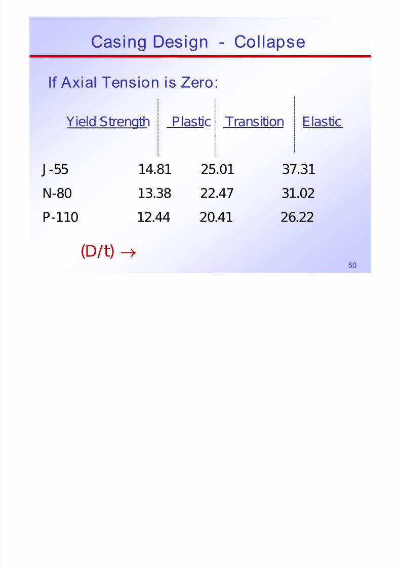
If Axial Tension is Zero:
Yield Strength Plastic Transition Elastic
→ )t/D(
J -55 14.81 25.01 37.31
N-80 13.38 22.47 31.02
P-110 12.44 20.41 26.22
Casing Design - Collapse

7/30/2019 4 Casing Design
http://slidepdf.com/reader/full/4-casing-design 46/103
46
Casing Design
Collapse pressure - with axial stress
1.
⎪
⎭
⎪⎬⎫
⎪
⎩
⎪⎨⎧
⎟⎟ ⎠
⎞⎜⎜⎝
⎛ −
⎥⎥
⎦
⎤
⎢⎢
⎣
⎡
⎟⎟ ⎠
⎞⎜⎜⎝
⎛ −=
P
A
2/12
P
APPA
Y
S5.0
Y
S75.01 Y Y
YPA = yield strength of axial stressequivalent grade, psi
YP = minimum yield strength of pipe, psi
SA = Axial stress, psi (tension is positive)
7/30/2019 4 Casing Design
http://slidepdf.com/reader/full/4-casing-design 47/103
47
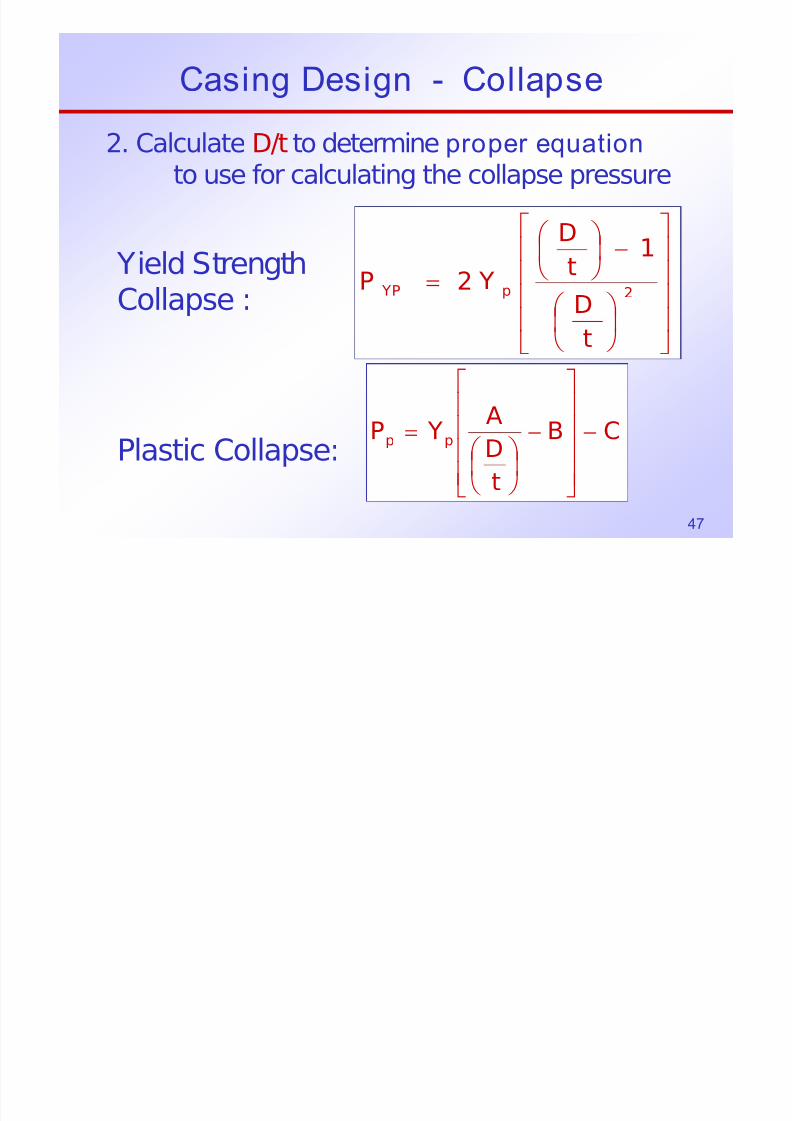
Casing Design - Collapse
2. Calculate D/t to determine proper equation
to use for calculating the collapse pressure
Yield Strength
Collapse :
Plastic Collapse:
⎥⎥⎥⎥
⎦
⎤
⎢⎢⎢⎢
⎣
⎡
⎟ ⎠ ⎞⎜
⎝ ⎛
−⎟ ⎠
⎞⎜⎝
⎛
=2p YP
tD
1t
D
Y2P
CB
t
DA YP pp −
⎥⎥⎥⎥
⎦
⎤
⎢⎢⎢⎢
⎣
⎡
−
⎟ ⎠
⎞⎜⎝
⎛ =
C C ’

7/30/2019 4 Casing Design
http://slidepdf.com/reader/full/4-casing-design 48/103
48
Transition
Collapse:
Elastic
Collapse:
⎥⎥⎥
⎥
⎦
⎤
⎢⎢⎢
⎢
⎣
⎡
−⎟ ⎠
⎞⎜⎝
⎛ = G
t
D
F YP p T
2
6
E
1t
D
t
D
10X95.46
P⎥⎦
⎤⎢⎣
⎡−⎟
⎠
⎞⎜⎝
⎛ ⎟ ⎠
⎞⎜⎝
⎛ =
Casing Design - Collapse, cont’d
E l 2
7/30/2019 4 Casing Design
http://slidepdf.com/reader/full/4-casing-design 49/103
49
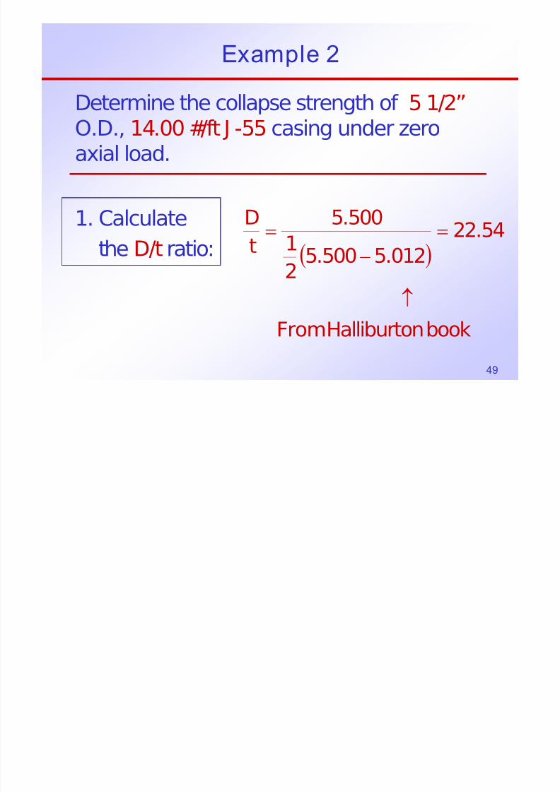
Example 2
Determine the collapse strength of 5 1/2”O.D., 14.00 #/ft J -55 casing under zero
axial load.
1. Calculatethe D/t ratio: ( )
booknHalliburtoFrom
54.22
012.5500.52
1500.5
tD
↑
=−
=
C C
7/30/2019 4 Casing Design
http://slidepdf.com/reader/full/4-casing-design 50/103
50
If Axial Tension is Zero:
Yield Strength Plastic Transition Elastic
→ )t/D(
J -55 14.81 25.01 37.31
N-80 13.38 22.47 31.02
P-110 12.44 20.41 26.22
Casing Design - Collapse
Example 2

7/30/2019 4 Casing Design
http://slidepdf.com/reader/full/4-casing-design 51/103
51
Example 2
2. Check the mode of collapse
Table (above) shows that,
for J -55 pipe,with 14.81 < D/t < 25.01
the mode of failure is plastic collapse.
54.22=t
D
C i D i C ll

7/30/2019 4 Casing Design
http://slidepdf.com/reader/full/4-casing-design 52/103
52
Casing Design - Collapse
Calculate D/t to determine proper equation touse for calculating the collapse pressure
Plastic Collapse: CB
t
DA YP pp −
⎥⎥⎥⎥
⎦
⎤
⎢⎢⎢⎢
⎣
⎡
−
⎟ ⎠
⎞⎜⎝
⎛ =
Example 2

7/30/2019 4 Casing Design
http://slidepdf.com/reader/full/4-casing-design 53/103
53
Example 2
The plastic collapse is calculated from:
206,10541.054.22
991.2000,55
CBt/D
A YP pp
−⎥⎦
⎤⎢⎣
⎡−=
−⎟ ⎠ ⎞⎜
⎝ ⎛ −=
psi117,3P p =Halliburton Tablesrounds off to 3,120 psi
Example 3
7/30/2019 4 Casing Design
http://slidepdf.com/reader/full/4-casing-design 54/103
54
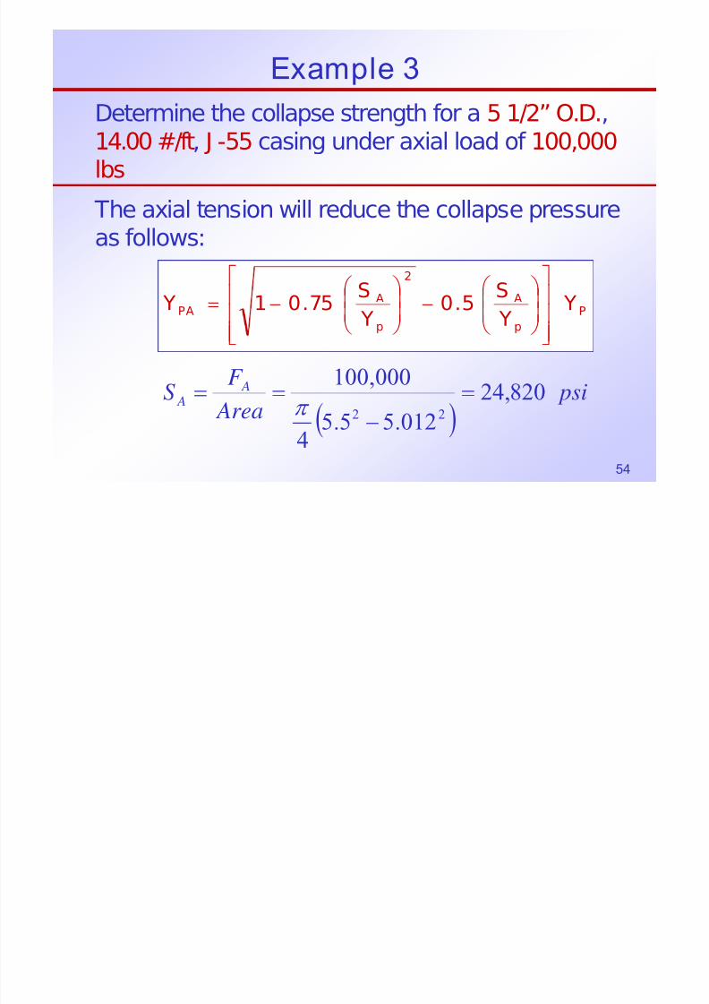
Example 3
Determine the collapse strength for a 5 1/2” O.D.,14.00 #/ft, J -55 casing under axial load of 100,000lbs
The axial tension will reduce the collapse pressureas follows:
P
p
A2
p
APA Y
Y
S5.0
Y
S75.01 Y
⎥⎥⎥
⎦
⎤
⎢⎢⎢
⎣
⎡⎟⎟
⎠
⎞⎜⎜
⎝
⎛ −⎟⎟
⎠
⎞⎜⎜
⎝
⎛ −=
( ) psi
Area
F S A A 820,24
012.55.54
000,100
22
=−
==π
Example 3 cont’d AA YS S
Y ⎥⎤
⎢⎡
⎟ ⎞
⎜⎛
⎟ ⎞
⎜⎛
507501
2

7/30/2019 4 Casing Design
http://slidepdf.com/reader/full/4-casing-design 55/103
55
Example 3 cont d
The axial tension will reduce the collapsepressure rating to:
psi216,38
000,55000,55
820,245.0
000,55
820,2475.01 Y
2
PA
=
⎥⎥
⎦
⎤
⎢⎢
⎣
⎡⎟ ⎠
⎞⎜⎝
⎛ −⎟
⎠
⎞⎜⎝
⎛ −=
Here the axial load decreased the J-55
rating to an equivalent “J-38.2” rating
P
p
A
p
APA Y
Y Y Y
⎥⎥⎥
⎦⎢⎢⎢
⎣
⎟⎟
⎠⎜⎜
⎝ −
⎟⎟
⎠⎜⎜
⎝ −= 5.075.01
Example 3 cont’d
7/30/2019 4 Casing Design
http://slidepdf.com/reader/full/4-casing-design 56/103
56
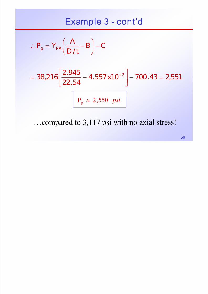
Example 3 - cont d
551,243.70010x557.4
54.22
945.2216,38
CBt/D
A YP
2
PAp
=−⎥⎦
⎤⎢⎣
⎡−=
−⎟ ⎠
⎞⎜⎝
⎛ −=∴
−
psi550,2P p ≈
…compared to 3,117 psi with no axial stress!
Example 3 cont’d

7/30/2019 4 Casing Design
http://slidepdf.com/reader/full/4-casing-design 57/103
57
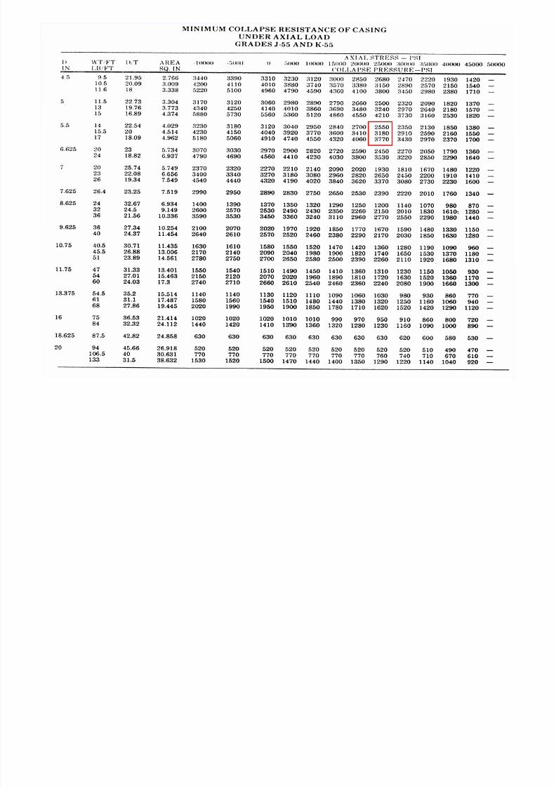
Example 3 - cont d
We shall be using API Tables to correct for theeffect of axial tension on collapse strength of casing.
The Halliburton Cementing Tables list thecollapse resistance of 5 ½ -in, 14.00 lb/ft J -55casing at 3,120 psi.
The axial tension in this case would derate the
collapse strength to about 2,550 psi.

7/30/2019 4 Casing Design
http://slidepdf.com/reader/full/4-casing-design 58/103
58
Combined Loading

7/30/2019 4 Casing Design
http://slidepdf.com/reader/full/4-casing-design 59/103
59
7/30/2019 4 Casing Design
http://slidepdf.com/reader/full/4-casing-design 60/103
60

7/30/2019 4 Casing Design
http://slidepdf.com/reader/full/4-casing-design 61/103
61
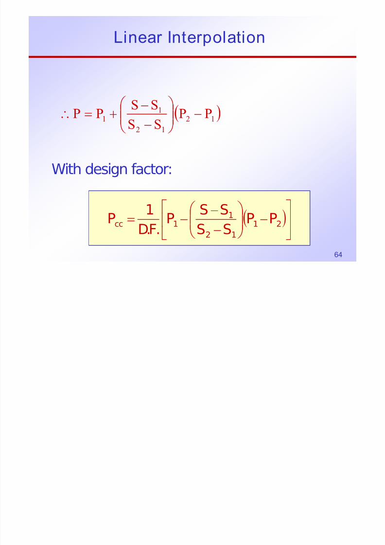
Linear Interpolation

7/30/2019 4 Casing Design
http://slidepdf.com/reader/full/4-casing-design 62/103
62
p
(iii) CmSP
(ii) CmSP
(i) CmSP
cmxy
22
11
+=
+=+=
+=
Linear Interpolation

7/30/2019 4 Casing Design
http://slidepdf.com/reader/full/4-casing-design 63/103
63
ea te po at o
⇒−=−− )SS(mPP )ii()iii( 1212
12
12
S S PPm
−−=
)()(P )()(1
12
12
11
S S S S
PPS S mPiii −
⎟
⎟
⎠
⎞
⎜
⎜
⎝
⎛
−
−=−=−−
Linear Interpolation
7/30/2019 4 Casing Design
http://slidepdf.com/reader/full/4-casing-design 64/103
64
p
( )12
12
11 PP
SSSSPP −⎟⎟
⎠ ⎞⎜⎜
⎝ ⎛
−−+=∴
With design factor:
( )⎥⎦
⎤⎢⎣
⎡−⎟⎟
⎠
⎞⎜⎜⎝
⎛
−
−−= 21
12
11cc PP
SS
SSP
.F.D
1P

7/30/2019 4 Casing Design
http://slidepdf.com/reader/full/4-casing-design 65/103
65
α = dogleg severity, deg/100 ft
= angle build rate, deg/100 ft
απ= 00018,RadiusBuild
Length of arc, L = R∆θRL

7/30/2019 4 Casing Design
http://slidepdf.com/reader/full/4-casing-design 66/103
66
∆L = (R + r)∆θ - R∆θ
θ∆=θ∆=∆ 2drL n
( ) 180100122
d
L2
d
L
L nn πα=
θ∆=
∆=ε∆
nn
6
d218d
180400,2
10*30E α=α
π=ε∆=σ∆
nd218α=σ∆
∆θR + rR
g R
snAd218F α= (7.14a)
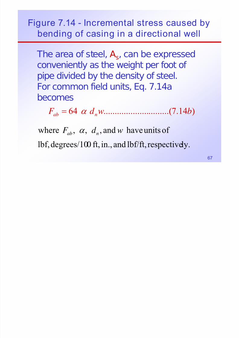
Figure 7.14 - Incremental stress caused by
7/30/2019 4 Casing Design
http://slidepdf.com/reader/full/4-casing-design 67/103
67
bending of casing in a directional well
The area of steel, As, can be expressed
conveniently as the weight per foot of pipe divided by the density of steel.For common field units, Eq. 7.14a
becomes
)14.7.........(....................64 bwd F nab α =
ly.respectivelbf/ft,and in.,ft,0degrees/10lbf,
of unitshave and ,,, where wd F nab α
Example

7/30/2019 4 Casing Design
http://slidepdf.com/reader/full/4-casing-design 68/103
68
)14.7.........(....................64 bwd F nab α =
/53 in7
100deg/5
,
ft lbf wd
ft
n
=
=
=α
Fab
= 64 * 5 * 7 * 35 = 74,400 lbf
Fab = 74,400 lbf
Casing Design Example

7/30/2019 4 Casing Design
http://slidepdf.com/reader/full/4-casing-design 69/103
69
g g p
Example Problem
API Design Factors
“Worst Possible Conditions”
Effect of Axial Tension on Collapse Strength
Iteration and Interpolation
Design for Burst, Collapse and Tension
Casing Design Example

7/30/2019 4 Casing Design
http://slidepdf.com/reader/full/4-casing-design 70/103
70
Design a 9 5/8-in., 8,000-ft combinationcasing string for a well where the mud wt.will be 12.5 ppg and the formation porepressure is expected to be 6,000 psi.
Only the grades and weights shown areavailable (N-80, all weights). Use API
design factors.
Design for “worst possible conditions.”
Casing Design - Solution

7/30/2019 4 Casing Design
http://slidepdf.com/reader/full/4-casing-design 71/103
71
g g
Before solving this problem is it necessary tounderstand what we mean by “Design Factors”
and “worst possible conditions”.
API Design Factors
Design factors are essentially “safety factors”that allow us to design safe, reliable casingstrings. Each operator may have his own set
of design factors, based on his experience,and the condition of the pipe.
Casing Design

7/30/2019 4 Casing Design
http://slidepdf.com/reader/full/4-casing-design 72/103
72
Casing Design
In PETE 661, we’ll use the design factorsrecommended by the API unless otherwise
specified.
These are the API design Factors:
Tension and J oint Strength: N T = 1.8
Collapse (from external pressure): Nc= 1.125Burst (from internal pressure): Ni = 1.1
Casing Design

7/30/2019 4 Casing Design
http://slidepdf.com/reader/full/4-casing-design 73/103
73
g g
What this means is that, for example, if we
need to design a string where the maximumtensile force is expected to be 100,000 lbf ,we select pipe that can handle 100,000 * 1.8
= 180,000 lbf in tension.
Note that the Halliburton Cementing Tables
list actual pipe strengths, without safetyfactors built in.
Casing Design

7/30/2019 4 Casing Design
http://slidepdf.com/reader/full/4-casing-design 74/103
74
Unless otherwise specified in a particularproblem, we shall also assume the following:
Worst Possible Conditions
1. For Collapse design, assume that thecasing is empty on the inside (p = 0 psig)
2. For Burst design, assume no “backup”fluid on the outside of the casing (p = 0 psig)
Casing Design

7/30/2019 4 Casing Design
http://slidepdf.com/reader/full/4-casing-design 75/103
75
Worst Possible Conditions, cont’d
3. For Tension design,assume no buoyancy effect
4. For Collapse design,
assume no buoyancy effect
The casing string must be designed to stand up to the
expected conditions in burst, collapse and tension.
Above conditions are quite conservative. They are also
simplified for easier understanding of the basic concepts.
Casing Design - Solution

7/30/2019 4 Casing Design
http://slidepdf.com/reader/full/4-casing-design 76/103
76
Burst Requirements (based on the expected pore
pressure)
The whole casing string must be capable of withstanding this internal pressure without failing inburst.
psi600,6P
1.1* psi000,6
Factor Design* pressure poreP
B
B
=
=
=
D e p t h
Pressure
Casing Design - Solution

7/30/2019 4 Casing Design
http://slidepdf.com/reader/full/4-casing-design 77/103
77
Collapse Requirements
For collapse design, we start at the bottomof the string and work our way up.
Our design criteria will be based onhydrostatic pressure resulting from the 12.5ppg mud that will be in the hole when the
casing string is run, prior to cementing.
Casing Designe
p t h

7/30/2019 4 Casing Design
http://slidepdf.com/reader/full/4-casing-design 78/103
78
Collapse Requirements, cont’d
severelessare
tsrequiremencollapsetheholetheupFurther
.bottomtheatd'reqpsi850,5P125.1*000,8*5.12*052.0
factordesign*depth*weightmud*052.0P
c
c
←=
=
=
D e
Pressure
Casing Design

7/30/2019 4 Casing Design
http://slidepdf.com/reader/full/4-casing-design 79/103
79
Req’d: Burst: 6,600 psi Collapse: 5,850 psi
Casing Design

7/30/2019 4 Casing Design
http://slidepdf.com/reader/full/4-casing-design 80/103
80
Note that two of the weights of N-80 casingmeet the burst requirements, but only the
53.5 #/ft pipe can handle the collapserequirement at the bottom of the hole (5,850psi).
The 53.5 #/ft pipe could probably run all theway to the surface (would still have to checktension), but there may be a lower costalternative.
Casing Design
7/30/2019 4 Casing Design
http://slidepdf.com/reader/full/4-casing-design 81/103
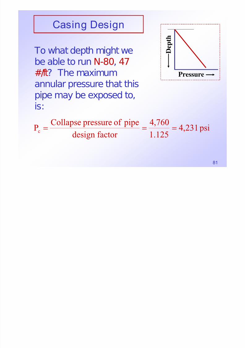
81
To what depth might webe able to run N-80, 47#/ft? The maximumannular pressure that this
pipe may be exposed to,is:
psi231,4125.1
760,4
factor design
pipeof pressureCollapse
Pc===
D e p t h
Pressure
Casing Design

7/30/2019 4 Casing Design
http://slidepdf.com/reader/full/4-casing-design 82/103
82
First Iteration
At what depth do we see this pressure (4,231psig) in a column of 12.5 #/gal mud?
ft509,65.12*052.0
231,45.12*052.0
Ph
h*5.12*052.0P
c1
1c
===∴
=

7/30/2019 4 Casing Design
http://slidepdf.com/reader/full/4-casing-design 83/103
Casing Design

7/30/2019 4 Casing Design
http://slidepdf.com/reader/full/4-casing-design 84/103
84
Weight, W1 = 53.5 #/ft * 1,491 ft= 79,769 lbf
This weight results in an axialstress in the 47 #/ft pipe
psi877,5
in13.572
lbf 769,79
areaend
weightSof
21 ===
Casing Design
7/30/2019 4 Casing Design
http://slidepdf.com/reader/full/4-casing-design 85/103
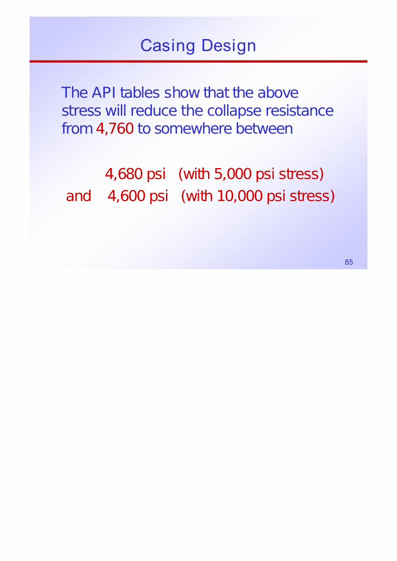
85
The API tables show that the above
stress will reduce the collapse resistancefrom4,760 to somewhere between
4,680 psi (with 5,000 psi stress)
and 4,600 psi (with 10,000 psi stress)
Casing Design

7/30/2019 4 Casing Design
http://slidepdf.com/reader/full/4-casing-design 86/103
86
Interpolation between these values showsthat the collapse resistance at 5,877 psi
axial stress is:
psi148,4125.1
666,4P
psi666,4)600,4680,4(*)000,5000,10(
)000,5877,5(680,4P
cc1
1c
==
=−−
−−=
With the design factor,
( )21
12
11c1P PP
S S
S S P −⎟⎟
⎠
⎞⎜⎜⎝
⎛
−
−−=
Casing Design

7/30/2019 4 Casing Design
http://slidepdf.com/reader/full/4-casing-design 87/103
87
This (4,148 psig) is the pressure at a
depth
Which differs considerably from the
initial depth of 6,509 ft, so a seconditeration is required.
ft382,65.12*052.0
148,4h2 ==

7/30/2019 4 Casing Design
http://slidepdf.com/reader/full/4-casing-design 88/103
88

7/30/2019 4 Casing Design
http://slidepdf.com/reader/full/4-casing-design 89/103
89
Casing Design

7/30/2019 4 Casing Design
http://slidepdf.com/reader/full/4-casing-design 90/103
90
Second Iteration
Now consider running the 47 #/ftpipe to the new depth of 6,382 ft.
psi378,6in572.13lbf 563,86S
lbf 563,865.53*)382,6000,8(W
22
2
==
=−=
Casing Design
I t l ti i

7/30/2019 4 Casing Design
http://slidepdf.com/reader/full/4-casing-design 91/103
91
Interpolating again,
This is the pressure at a depth of
( ) psi pcc 140,4600,4680,4*5000
5000378,6
680,4125.1
1
2=
⎭⎬
⎫
⎩⎨
⎧
⎥⎦
⎤
⎢⎣
⎡−
−−=
ft369,65.12*052.0
140,4h 3 ==
( )⎥
⎥
⎦
⎤
⎢
⎢
⎣
⎡−
⎟
⎟
⎠
⎞
⎜
⎜
⎝
⎛
−
−−=
2112
1
1c1 D.F.
1P PP
S S
S S P
Casing Design
Thi i ithi 13 ft f th d l If

7/30/2019 4 Casing Design
http://slidepdf.com/reader/full/4-casing-design 92/103
92
This is within 13 ft of the assumed value. If more accuracy is desired (generally not
needed), proceed with the:Third Iteration
psi429,6572.13
259,87S
lbf 259,875.53*)369,6000,8(W'369,6h
3
3
3
==
=−==
Pcc3 = ?
Casing Design

7/30/2019 4 Casing Design
http://slidepdf.com/reader/full/4-casing-design 93/103
93
Third Iteration, cont’d
2
3
140,4
)600,4680,4(*
000,5
000,5429,6680,4
125.1
1
cc
cc
P psi
Pthus
==
⎭
⎬⎫
⎩
⎨⎧
−−
−=
Casing Design

7/30/2019 4 Casing Design
http://slidepdf.com/reader/full/4-casing-design 94/103
94
Third Iteration, cont’d
This is the answer we are looking for, i.e.,we can run 47 #/ftN-80 pipe to a depth of 6,369 ft, and 53.5 #/ft pipe between 6,369
and 8,000 ft.Perhaps this string will run all the way to thesurface (check tension), or perhaps an evenmore economical string would include some43.5 #/ft pipe?
Casing Design

7/30/2019 4 Casing Design
http://slidepdf.com/reader/full/4-casing-design 95/103
95
At some depth the 43.5 #/ft pipe would be
able to handle the collapse requirements,but we have already determined that it willnot meet burst requirements.
! NO∴
N-80
43 5 #/ft?

7/30/2019 4 Casing Design
http://slidepdf.com/reader/full/4-casing-design 96/103
96
N-8053.5 #/ft
N-8047.0 #/ft
43.5 #/ft?Depth = 5,057?
5,066?5,210?
Depth = 6,3696,3696,382
6,509
8,000
Tension Check

7/30/2019 4 Casing Design
http://slidepdf.com/reader/full/4-casing-design 97/103
97
The weight on the top joint of casing
would be
With a design factor of 1.8 for tension, a
pipe strength of
weightactual602,386
)/#5.53*631,1()/#0.47*369,6(
lbs
ft ft ft ft
=
+
required islbf 080,695602,386*8.1 =
Tension Check

7/30/2019 4 Casing Design
http://slidepdf.com/reader/full/4-casing-design 98/103
98
The Halliburton cementing tables give a
yield strength of 1,086,000 lbf for the pipebody and a joint strength of 905,000 lbf forLT & C.
surfacetoOK isft/#0.47∴
Casing Design Review

7/30/2019 4 Casing Design
http://slidepdf.com/reader/full/4-casing-design 99/103
99
We have 4 different weights of casingavailable to us in this case:
1. Two of the four weights are unacceptableto us everywhere in the string becausethey do not satisfy the burstrequirements.
2. Only the N-80, 53.5 #/ft pipe is capable of withstanding the collapse requirementsat the bottom of the string
Casing Design Review
7/30/2019 4 Casing Design
http://slidepdf.com/reader/full/4-casing-design 100/103
100
3. Since the 53.5 #/ft pipe is the mostexpensive, we want to use as little of it
as possible, so we want to use asmuch 47.0 #/ft pipe as possible.
4. Don’t forget to check to make sure thetension requirements are met; both for
pipe body, and for threads andcouplings (T&C).
Casing Design Review
7/30/2019 4 Casing Design
http://slidepdf.com/reader/full/4-casing-design 101/103
101
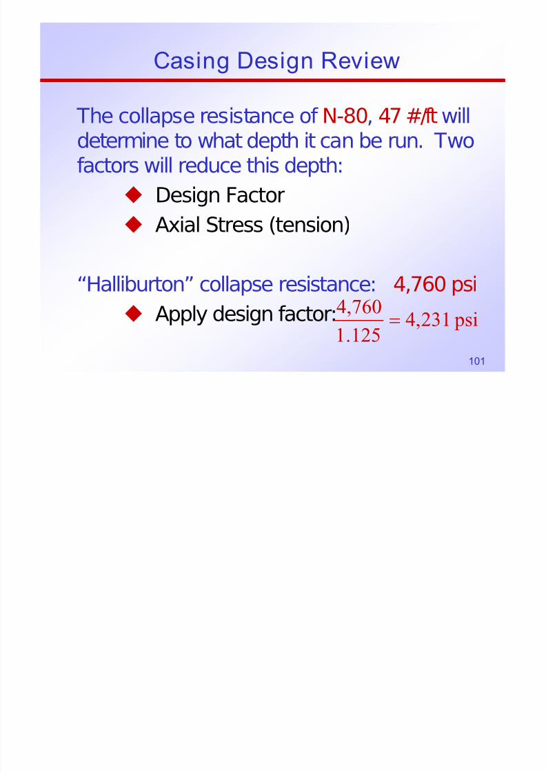
The collapse resistance of N-80, 47 #/ft willdetermine to what depth it can be run. Twofactors will reduce this depth:
Design Factor
Axial Stress (tension)
“Halliburton” collapse resistance: 4,760 psi Apply design factor: psi231,4
125.1
760,4=
Casing Design Review

7/30/2019 4 Casing Design
http://slidepdf.com/reader/full/4-casing-design 102/103
102
To determine the effect of axial stressrequires an iterative process:
1. Determine the depth capability without
axial stress
2. Determine axial stress at this point
ft509,65.12*052.0
231,4depth ==
Casing Design Review
3 Determine corresponding collapse resistance

7/30/2019 4 Casing Design
http://slidepdf.com/reader/full/4-casing-design 103/103
103
3. Determine corresponding collapse resistance
4. Determine depth where this pressure exists
5. Compare with previous depth estimate
6. Repeat steps 2-6 using the new depthestimate
7. When depths agree, accept answer(typically 2-4 iterations) (agreement towithin 30 ft will be satisfactory)


