18
0 MCE DD 2014 2/14/2014 2/14/2014 17TR8 – HPHT Design Guideline for Subsea Equipment Brian Skeels – FMC Technologies
0 MCE DD 2014 2/14/2014 2/14/2014
17TR8 – HPHT Design Guideline for Subsea Equipment
Brian Skeels – FMC Technologies

1 MCE DD 2014 2/14/2014
In the Beginning… API 6HP – primarily focused on
burst before leak and 25k BOP equipment being too heavy – 1.5 x RWP
vs. 1.25 x RWP? External hydrostatic pressure to compensate?
Next was API PER 15K to identify all wellbore issues and challenges associated with HPHT (anything above 15k RWP) from sand face to pipeline – looked at things holistically But PER 15K points to the problems that
each API Subcommittee needs to address – never intended to “solve” them… it is not
a design guideline
API 17TR8 is Subsea’ s attempt at providing some of the guideline solutions.

2 MCE DD 2014 2/14/2014
Holistic View – 1PER15K-1 Tells you what to be looking out for…

3 MCE DD 2014 2/14/2014
How is HPHT Defined? What Code Rules?
Source: OTC 17927, 23943, 25376
Stre
ngth
Der
atin
g
Fast Fracture
ASME VIII Div. 2 ASME VIII Div. 3

4 MCE DD 2014 2/14/2014
When is a Pressure Vessel Thin or Thick-Walled?
Lamé decided that a pressure vessel should be considered ‘Thick-Walled’ if t/d>0.05
As a very rough guide Lamé’s criteria
makes pressure vessels up to 5000 psi are Thin-Walled and most pressure vessels greater than 5000 psi are Thick-Walled
Lamé July 22, 1795 - May 1, 1870
ASME decided that a pressure vessel should be considered ‘Thick-Walled’ if r/t ≤ 4
As a very rough guide ASME’s criteria
makes pressure vessels up to 10000 psi are Thin-Walled and most pressure vessels greater than 10000 psi are Thick-Walled

5 MCE DD 2014 2/14/2014
When is a Pressure Vessel Thin or Thick-Walled?
Lamé decided that a pressure vessel should be considered ‘Thick-Walled’ if t/d>0.05
As a very rough guide Lamé’s criteria
makes pressure vessels up to 5000 psi are Thin-Walled and most pressure vessels greater than 5000 psi are Thick-Walled
Lamé July 22, 1795 - May 1, 1870
ASME decided that a pressure vessel should be considered ‘Thick-Walled’ if r/t ≤ 4
As a very rough guide ASME’s criteria
makes pressure vessels up to 10000 psi are Thin-Walled and most pressure vessels greater than 10000 psi are Thick-Walled
Thin-Walled Pressure Vessel Model –
Leak Before Burst Division 2
Thick-Walled Pressure Model -Fast Fracture
Failure Division 3

6 MCE DD 2014 2/14/2014
15k to 25k a design transition zone
Elastic stress Elastic-Plastic / Fracture Mech. stress
Source: OTC 23621
Thicker wall sections changes the “pressure vessel model”, but where? Don’t know where leak before burst ends and fast fracture failure begins

7 MCE DD 2014 2/14/2014
17TR8: The HPHT Method
• Design Methodology – roadmap for transition from Div 2 to Div 3
• Populate oil field material data sheets at elevated temperatures • Establish physical properties
and QA lists • Establish HPHT validation tests
• Extended function testing standard
• Guidance for project specific testing
HPHT Design
8 MCE DD 2014 2/14/2014
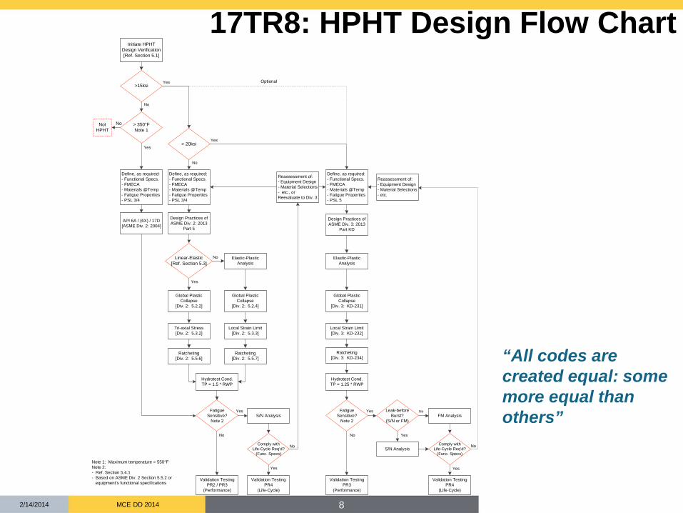
17TR8: HPHT Design Flow Chart
Linear-Elastic[Ref. Section 5.3]
Tri-axial Stress [Div. 2: 5.3.2]
Ratcheting[Div. 2: 5.5.6]
Local Strain Limit [Div. 2: 5.3.3]
Ratcheting[Div. 2: 5.5.7]
Validation TestingPR2 / PR3
(Performance)
FatigueSensitive?
Note 2
Local Strain Limit [Div. 3: KD-232]
Ratcheting[Div. 3: KD-234]
Validation TestingPR4
(Life-Cycle)
Hydrotest Cond.TP = 1.5 * RWP
Validation TestingPR3
(Performance)
S/N Analysis
Validation TestingPR4
(Life-Cycle)
FatigueSensitive?
Note 2
Comply withLife-Cycle Req’d?
(Func. Specs)
Comply withLife-Cycle Req’d?
(Func. Specs)
Reassessment of:- Equipment Design- Material Selections- etc.
Leak-before Burst?
(S/N or FM)FM Analysis
No Yes
No
Yes
Yes
Yes
Yes
No No
No
API 6A / (6X) / 17D[ASME Div. 2: 2004]
>15ksi
> 350°FNote 1
> 20ksi
Yes
Yes
No
Not HPHT
No
S/N Analysis
Reassessment of:- Equipment Design- Material Selections- etc., orReevaluate to Div. 3
Hydrotest Cond.TP = 1.25 * RWP
No
No
Initiate HPHTDesign Verification[Ref. Section 5.1]
Yes
Define, as required:- Functional Specs.- FMECA - Materials @Temp- Fatigue Properties- PSL 3/4
Design Practices ofASME Div. 2: 2013
Part 5
Design Practices ofASME Div. 3: 2013
Part KD
Global Plastic Collapse
[Div. 2: 5.2.4]
Global Plastic Collapse
[Div. 2: 5.2.2]
Global Plastic Collapse
[Div. 3: KD-231]
Yes
Define, as required:- Functional Specs.- FMECA - Materials @Temp- Fatigue Properties- PSL 3/4
Define, as required:- Functional Specs.- FMECA - Materials @Temp- Fatigue Properties- PSL 5
Optional
Elastic-PlasticAnalysis
Elastic-PlasticAnalysis
Note 1: Maximum temperature = 550°F Note 2: - Ref. Section 5.4.1 - Based on ASME Div. 2 Section 5.5.2 or equipment’s functional specifications
“All codes are created equal: some more equal than others”

9 MCE DD 2014 2/14/2014
17TR8: HPHT Design Flow Chart
Linear-Elastic[Ref. Section 5.3]
Tri-axial Stress [Div. 2: 5.3.2]
Ratcheting[Div. 2: 5.5.6]
Local Strain Limit [Div. 2: 5.3.3]
Ratcheting[Div. 2: 5.5.7]
Validation TestingPR2 / PR3
(Performance)
FatigueSensitive?
Note 2
Local Strain Limit [Div. 3: KD-232]
Ratcheting[Div. 3: KD-234]
Validation TestingPR4
(Life-Cycle)
Hydrotest Cond.TP = 1.5 * RWP
Validation TestingPR3
(Performance)
S/N Analysis
Validation TestingPR4
(Life-Cycle)
FatigueSensitive?
Note 2
Comply withLife-Cycle Req’d?
(Func. Specs)
Comply withLife-Cycle Req’d?
(Func. Specs)
Reassessment of:- Equipment Design- Material Selections- etc.
Leak-before Burst?
(S/N or FM)FM Analysis
No Yes
No
Yes
Yes
Yes
Yes
No No
No
API 6A / (6X) / 17D[ASME Div. 2: 2004]
>15ksi
> 350°FNote 1
> 20ksi
Yes
Yes
No
Not HPHT
No
S/N Analysis
Reassessment of:- Equipment Design- Material Selections- etc., orReevaluate to Div. 3
Hydrotest Cond.TP = 1.25 * RWP
No
No
Initiate HPHTDesign Verification[Ref. Section 5.1]
Yes
Define, as required:- Functional Specs.- FMECA - Materials @Temp- Fatigue Properties- PSL 3/4
Design Practices ofASME Div. 2: 2013
Part 5
Design Practices ofASME Div. 3: 2013
Part KD
Global Plastic Collapse
[Div. 2: 5.2.4]
Global Plastic Collapse
[Div. 2: 5.2.2]
Global Plastic Collapse
[Div. 3: KD-231]
Yes
Define, as required:- Functional Specs.- FMECA - Materials @Temp- Fatigue Properties- PSL 3/4
Define, as required:- Functional Specs.- FMECA - Materials @Temp- Fatigue Properties- PSL 5
Optional
Elastic-PlasticAnalysis
Elastic-PlasticAnalysis
Note 1: Maximum temperature = 550°F Note 2: - Ref. Section 5.4.1 - Based on ASME Div. 2 Section 5.5.2 or equipment’s functional specifications
API 6A/6X, 17D
ASME Div 2
ASME Div 3
Path selected determines:
Test pressure, Design margins,
QA
1.5xRWP 1.5xRWP
1.25xRWP
“All codes are created equal: some more equal than others”

10 MCE DD 2014 2/14/2014
Quality and Qualification Requirements
“Buckets” to capture physical properties and performance tests: PSL 5 to address tighter QA requirements in material strength (+/- range), ovality,
cross section thinning, chemistry, prolongations, stress relaxation properties, etc. PR 3 to address extended functioning component at HPHT conditions; gas test
medium, blow down safety, more temperature cycles, etc. PR 4 to address cyclic loading, fracture mechanics S-N fatigue, criticality and
project specific cyclic design life
PSL 5 PR 3 PR 4

11 MCE DD 2014 2/14/2014
17TR8: HPHT Materials Properties
PSL 5
Design Properties * • Mechanical Properties
– Tensile Properties (including tensile modulus)
– Fracture Toughness (K1c ) ***
– Crack Growth Rate (da/dN)*** – Fatigue S-N curve***
• Physical Properties – Thermal conductivity – Specific heat capacity – Density – Thermal expansion – Poisson Ratio – NACE Test (2% or defined strain limit) – Stress Relaxation
Quality Control ** • Chemistry / Composition
Requirements • Mechanical Properties
– Tensile Properties (tight range) – Charpy , CTOD – Hardness
• Microstructure and Grain Size – NDE – Minimum Crack Size
• Process Control – Melting, Forging – Heat Treatment, QTC Prolongation
Testing – Dimensional – Ovality, Thinning
* For discrete temperatures 75, 350, 450, 550, 650 F
** For QC temperatures defined by ASME VIII, Div 3 *** at H2S, CO2, seawater conditions

12 MCE DD 2014 2/14/2014
17TR8: Seals and Fasteners
• Stress Relaxation defeat seal contact force? • Thermal growth changes seal pocket geometry and different
thermal expansion rates between seal and base material (seal pocket) may defeat or fatigue seal
• Corrosion (H2S – CO2, etc.) environment masks fatigue failures; need to investigate separately
Crush contact of BX Gasket
Bolt Loading
Hoop Stress Energized
Force
High Contact Compressive Stress
PL-M = Temp (log tr +C)
Larson-Miller Regression Curve

13 MCE DD 2014 2/14/2014
17TR8: Design Flow Chart – Fatigue Assessment
Validation TestingPR2 / PR3
(Performance)
FatigueSensitive?
Note 2
Validation TestingPR4
(Life-Cycle)
Validation TestingPR3
(Performance)
S/N Analysis
Validation TestingPR4
(Life-Cycle)
FatigueSensitive?
Note 2
Comply withLife-Cycle Req’d?
(Func. Specs)
Comply withLife-Cycle Req’d?
(Func. Specs)
Leak-before Burst?
(S/N or FM)FM Analysis
No Yes
Yes
Yes
Yes
No No
S/N Analysis
No
Fatigue Assessment: • Determine if equipment is fatigue sensitive ASME fatigue screening criteria (ASME Div. 2 Section 5.5.2)
internal – pressure/temperature; external – mechanical
• Fatigue analysis: S-N approach Fracture Mechanics (FM) approach
• May require: Load-monitoring NDE method capability and its probability of detection (PoD) to identify flaws Multiple flaws assessment
Non-uniform stress field – gray “above yield” Autofrettage Effect
Source: OTC 23063, 23621

14 MCE DD 2014 2/14/2014
Leak-Before-Burst Replaced by
Loss of Barrier
• Both Leak or Burst are catastrophic events because it’s hard to turn off a reservoir.
• Need a different differentiator • Oil industry has “two barrier” rule for safe operation. • Locations where a fatigue failure could compromise primary barrier are
critical and more detailed analysis – fracture mechanics
VXT (in the wellhead)
VXT (with Tubing Head)
HXT and EHXT
Tubing Hanger Subsea
Wellhead
Tubing Head
critical break
Less critical break – but where do you draw the
lines?

15 MCE DD 2014 2/14/2014
17TR8: HPHT Validation
• Can define within a “standard” • Additional Function Testing
– Extended testing at Temperature
• Can’t define within a “standard” • Fatigue Design Requirements
– S-N Curve for machined parts, welds, notches, etc.
– Fracture Mechanics • Define crack size, material toughness
– Define cycle life and cyclic testing • FMECA of Critical Components
– Additional project specific tests
PSL 5
PR 3
PR 4

16 MCE DD 2014 2/14/2014
• First edition to be balloted for publication in 2014 • Get the word out on HPHT Materials
Properties at temperature • Second edition - work still to be done in
2014 - 15 • Welding and cladding and
associated crack design issues • Refine cyclic and fatigue analysis • Add Sensors and Monitoring for
cycle life • Systems engineering of spec
breaks and interfaces • Work with ASME Div 3 to submit a
“code case”
Future of 17TR8
PSL 5

17 MCE DD 2014 2/14/2014
Thank You / Questions
17TR8 – HPHT Design Guideline for Subsea Equipment
Brian Skeels


