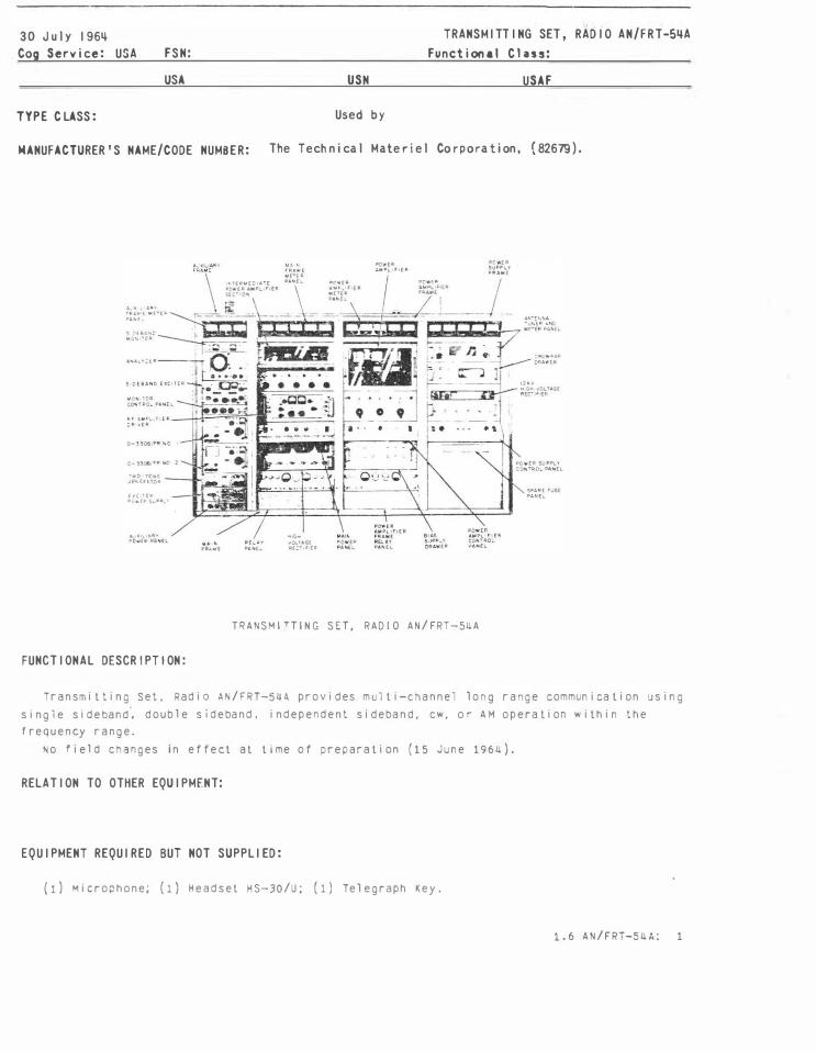
5 May 1 966 Cog Service: USN FSN : USA TYPE CLASS: MANUFACTURER ' S NAME/CODE NUMBER: USN Used by RAD I O SET AN/FRC-528 Functial Cl ass: USAF Commun i cat i on Co. , Inc., (13848). _, __ RADIO SET AN/F RC-528 FUHCTIOHAL DESCRIPT ION: Radio Set AN/FRC-528 is a ' i xed frequency s ingle or dua l channe l , crys ta l controlled, dual conversio n super-heterody ne type, desig ned for FM commun i cat ion in the 25 to 5� mc/s band, for use i n mobiTe or fixed sta tion equ i pment. Each freque ncy co nversion is cry stal control led using a separate crystal . The receive r is de signed for e i ther wide band or nar row band channel operation ard can be easily changed from o ne to the ot her. No field changes in effect a t t i me of prepara tion (1 December 1965 ). RELAT I ON TO OTHER EQUIPMENT: AN/FRC-528 is one way interchangeable with A N/FRC-52, and A N/F RC-52A . The AN />RC-52 8 i n- corporates tem perature con trol l ed c rystal s mounted in oven s. 1.7 AN/FRC-528: 1 c
Transcript
5 May 1 966 Cog Serv i ce : USN FSN :
USA
TYPE CLASS:
MANUFACTURER ' S NAME/CODE NUMBER:
USN
Used by
RAD I O SET AN/FRC-528 Functional C l ass:
USAF
Commun i cat i on Co. , Inc., ( 13848).
_._, __
RA D I O S E T AN/ FRC-528
FUHCTIOHAL DESCRIPT I ON :
Radio S e t AN/ FRC-528 i s a ' i xed frequency s i ng l e o r dual channe l , crys tal con t ro l l ed , dual con version super-he t erodyne t y p e , designed f or FM commun i cation in t he 2 5 t o 5� mc/s band , for u se i n mobiTe or fixed s t a tion equi pmen t . Each freque n cy convers i on is cry s ta l con t r o l l ed using a separa t e cry s tal . T h e receiver i s des i gned for e i ther wide band or narrow band channe l operation ard can be easil y changed from one to t he o t h e r .
No fie l d changes i n e f fe c t a t t i me o f prepara t i o n ( 1 December 1 9 6 5 ) .
RELAT I ON TO OTHER EQUIPMENT:
AN/FRC-528 is one way in terchangeable with A N/FRC-5 2 , and AN / FRC-52A . The A N/>RC-528 i ncorporate s t emperature con t rol l ed cry s tal s moun ted i n oven s .
1 . 7 AN/FRC-52 8 : 1
c
RAD I O SET A N/ FRC-526
EQU I PMENT R EQU IRED BUT NOT SUP? L I E D : �o�e.
TECHN I CA L CHARACTER I ST I CS:
FREQUENCY RANGE: 2 5 � o 5 4 �c/s.
SEL£CriVITY �A��WIDTH
2 x down (- 6 do) WIDEBA�D
;, o kc Is
52 ;,cfs
";t.PRQ..,BAtiD 1 2 "'I c;
100,000 x down (- 100 db)
85 do oo�n oy EIA Method 80 db dow� Dy EIA MP:�od
FREQUENCY STABILITY: ± 0.0005$ temp� rature cont-o l l ed, ± 0.0021 non-te�perature �on: rol l Pd.
Opt i o nal at decreas�Q price.
AMBIENT THIPf�ATJRE RAt.GE: -30 deg C to -r 60 del C (ext.,rior or case).
SENSITIVITY: 0.;) u·: or l ese; for 20 dJ noic;e c-.�ietir> or EIA met·.o1 o• �edSur.:.'"lPPt.
SQUELCH SEfiSITI;ITY: 0.2 uv or iess.
SPURIOUS RESPONSES: - 10C d� or DE'�i:e r.
AUDIO OUTPUT: 1.5 watts with l ess t tan 10$ d i sto rtio n.
AUDIO FREQUENCY RESPOhSE: W i th i n + 1 do to - 3 do of a 6 do p rr octave slope ove r �e re�Je
of .300 to 30�0 cycles (1000 cps ree rence ) .
ANTENNA INPUT 14PEDANCE: 52 onms.
AUD I 0 OUTPUT I�>PEDANCE: ll a nd 500 Clh"l"'.
RECEIVER CRYSTA_S CHANNEL DETt:Rt41�1N·3 CRYSTAL: Jrd :'lOLl :ype 7':. deg C :e"lperil tu re contro l l ed type, C0'4CO
par: 010. 209-6RA, S or c. ("'.:li' oe 'u.- n i shed .d:�out ten,pera:"··e contro' on spec i a l
oraer at decreased p r i ce, COM:O p;;rt no. 20!-!RA, a o- :) . OSCILLATOR RADIATION: O sc i l l ato r Rdd i at i on of ;ne cna n�el deter� i � i ng �'""ystal a nd/o r 2nj
C o n ve rs i o n Crystal does not exceed FCC reQu i reme n t s part 1 5 , S J �- pa r � c. POWER REQUIPEMENTS: 117 v aC, 50 to oO � yc l e� single p�.
E�ISSION: iype FJ. fREQUENCY CO�TROL: Crysta l .
POWER OUTPJT: 60 watt max.
QTY ITEM
Radio Set AN/FRC-528 inc l udes:
Rece i ver-Transm i t�er, Radio RT-407B/FRC-52
1 Antenn�, AT-7�9/U 1 Loca l Control Panel
Microphone
MAJOR COMPONENTS
Ca::�ine\, E l ect rical Eq u i prr>ent
1.7 A�/FPC-525: 2
DIME�Sic·.s (INCHES)
10-:/2 X 18-,3/4 X 2�-1/2
Nt IG!li (L1jS)
75
RAD I O SET AN/FRC-52 8
REFERENCE DATA AND L I TERATUR E :
NAVSH I PS 92 921(8 ) : Techn i c a l Manual for Rad i o Set A N /FRC-52, 52A , 528.
TUBE, CRYSTAL AND/OR SEM I -CONDUCTOR DATA:
TUB E S : (1 ) 5763 (1) 61!+6 (2) 12AX7
(2 ) 6AL5 (1 ) 6AQ5 (12) 68H6 (2) 12AT7
CRYSTALS : (2) 30 to 42 me (1) 3450 kc ( 1 ) CR-18A/U
SEM I -CON DUCTORS : (17) 1N51+0
SH I PP I NG DATA
PKGS VOLUME (cu FT)
PROCUREMENT DATA
(1 ) 12AU7
WE I GHT (Las )
PROCUR I NG SERV I CE: USN DESIGN COG : USN, BuShips SPEC &/OR DWG: SH I PS-B-4405
CONTRACTOR
commun i cation company, I n c .
LOCATI OM
Coral Gab l es , F l o rida
1. 7 AN/FRC-528: 3
CONTRACT OR ORDER NO.
NObs r 89532
APPROX. UN I T COST
(I) "'
,.. co
1 9 July 1 967 Cog Service: USN FSN :
USA USN
TYPE CLASS: Used by
Func t i onal C lass:
USAF
MANUFACTURER'S NAME/CODE NUMBER: General Elect r i c Co. ( 08771 )
RAD I O SfT AN/FRC-83
FUNCTIONAL DESCR I PT I ON :
RAD I O SET AN/FRC-83
R3d i o S e t AN / �RC-83 o p e r a t e s as a f i xed oase s tat i on for �se w i th moci l e Rad i o S e t s i n the 132 to 152 me ra n ge . Rec e i ve s s i gnals fro� moo i l e raoio sets and relays , t he s i gnal to a remo t e con t ro l un i t at some dist ance away . 1 t i s des i qn e d to De mou n t ed on t h e c ross-arm or a t e l e;.hone pol e . . ( "<o f i el d cnan�;es i'l effec t a t t 1 me of orepara t•on .>O �o\e"1oer 1965\. RELAT I ON TO OTHER EQU I PMENT: N o n e
EQU I PMENT REQU I RED BUT HOT SUPPL I ED : �one
TECH� I CAL CHARACTER I STICS:
TRAN SM I TTER DHA
FREQU t. N CY f\ANGE: 132 to ._52 me, 1 band , 1 chan n e l . EM I S S I 0 N : type F 3 .
POWER OUTPUT: 80 w maximum.
1 . 7 AN/��C-83: 1
RAD I O SET AN/FRC-83
REC E I V E R DATA
F R EQ U ENCY RAN G E : 132 to 152 rnc , 1 oano, 1 chanre l , EMISS I O N : t y p e F J ,
P O W E R P EQU I R EM EN T : 117 v ac, 60 eye, s i n] l e p'1.
T E M P E RATU R E R A N G E : JOdeg C t o 6 0d eg C(- 2 2F to 1 UQdAg F ).
QTY I TEM
1 Rad i o S e t AN / F RC-B 3 i nc l ud e s ; 1 1 1
RAce iver-T ransml • tPr, Radio RT-699 / F RC-83 , An t en n a AS- 1 U3B / F RC
REFERENCE DATA AHD L I TERATUR E :
MAJOR COMPONENTS
D I M EN S I O N S ( I N C H E S )
12-1/U X 27 X U2
N A VSH I PS 9u7ou: I n s t r u c tion Book for Rad i o Se t AN/ F RC-83 .
PKGS
P ROCU R I N G S E RV I C E : U S N
SH I PP I NG DATA
VOLUM E ( CU F T )
PROCUREMENT DATA
SPEC & / O R D'wG : SrliP S-R-4099
CONTRACTOR LOCAT I ON
General E l ec t r i c Co . Ly n c h o u r g , V A .
1 . 7 A N / F RC-8 3 : 2
DES I GN CO G : U S N ,
CONTRACT OR ORDER NO.
NO� s r-876U.3
W E I GHT ( L B S )
W E I G�T ( LB S )
BuSh i OS
A P PROX. UN I T COST
-CD CD
"' <Xl
1 8 Ju I y 1 967 Cog Service: USN FSN:
USA USN
TYPE CLASS: Used by
RAD I O SET AN/FRC-8ij Functional Class :
USAF
MANUFACTURER ' S NAME/CODE NUMBER: Len ku rt E l ectr i c Co. , lnc., ( 83Nij),
RADIO SET AN/FRC-84
FUNCT I ONAL DESCR I PT I ON :
Radio Set AII/ F PC-84 is a frequency modulated transmi�t1n;; ana Rece1vin; ecuipment used
in po1nt-to-po1nt shore-oasec, radio-relay linK sy:;'.ems. It IS a m1crowave syscem consis-
ting of one bay o• units, and associateo po�er s�pplies.
A basic transmitter-receiver assemoly accepts JOO voice cnannels s1r.gle s1ceoano suppresseo carrier. ProviSions have been made for the s1mulcaneous operation of up to four trans
mitters and receivers over a single antenna to meet hi:�-: raf • • c dens lty aemands ( 6 0 0 voice
channels frequency aiversity or 1200 voice channel non-diversity, h·Jt-standby operations).
This set may be utilized in several modes of·operations, such as •requency diversity, space diversity, and hot-standoy. The radio lin� is usually made up of a numoer of stations located at intervals of 20 to 40 miles. This equipment is aesigned to accommodate a •re-
quency aivision multiplex such as cne AN / FCC-17 . No fiela chanqes in effect at t1me of preparation (3: August 1967) .
RELAT I ON TO OTHER EQU I PMENT: None
1 . 7 A'l/ F RC-8 4 :
�AD I O SET AN/ FRC-8�
EQU I PMENT REQU I RE D BUT HOT SUPPL I ED : l1ot <�v-llla"Jle
TECHN I CAL C HARACTER I ST I CS :
r · :, l s�1 1 T r t: � TYPE EMISSION: F9, MAX PO��R C�TP�T: F RE!Jl Ei' CY R� '<G<: !�
. -!. . J•· . �c: 592" to
6;.7' t'J
712:: •o
77 50 to
FR£QUE'4CY STABILI-Y: ±o. nt. VIDEO INPUT 11-'PED��t:E: 75 Ol11r.S
5Q Gh'•lS norc •
�.::.. 6iP5.
- 7 5C.
sz.oc.
unoalc;ncec.
JUTPUT iMPt:D"�CE.
VIDEO INPUT LEVEL: -9 to -:to dDm .
RECEIVER
TYPE E'-'1SSI014 RECEIVE[: F9.
FnEQUE'lCY PAN:;E I'< t-'C: 1925 to 5!!25·
657'i to 6iJ7:,.
7125 to 77 :;o.
77!::C to 84C0. VI Dt:O C UT?Ul I>�PEDA'JCE: 75 Ji''1.3 u'l:J;:1anced.
NOISE FIGURE· lU ��· • •
VI DEC OUTPUT LEVEL: -1:; ot•m. POWER REOUI PE"ENTS: :15'1 ±10%, 47 to 100 eye, 1 p'l ac; 21�v. +� -2v uc; -'ilV, tc -sv JC .
QTY IH�
1 Racio Se t b.H/Fr.C-�4 ircluoes:
MAJOR COMPONENTS
Rr.dio Set U.S.�. CNO Lenf.urt. t.lcctric
Co. !nc. Type H<i-3200:.
1 �icrowave P�lay s�: �en�ur t Elec�ric c�. Inc. Type 74�-J20C1
REFERENCE DATA AND L I TERATURE:
Nomenclature Reque st .
P!<GS
PROCURING SERV ICE: USt.�
SPEC 6./0° OWG:
SH I PP I NG DATA
VOLUME (CJ FT)
PROCUREI-lEHT DATA
DI''E'JSIONS
{ IN':Hfg )
DE� I(,�� COG: USN, 3U:>H I P
\\EI :H
( l P<;)
RAD I O SET AH/FRC-8�
CONTRACTOR LOCAT I ON
Lenkurt El �-= tr i c Co. Inc. San Carlos. Calif.
1 . 7 AN/ FRC-8 11 : 3
CONTRACT OR ORDER NO.
N 6 0 0 ( 1 1 ) 59 326
APPROX. UN IT COST
� Apn l 1966 Cog Servi c�e�:�u�SH�--�FS�H�:�---
USA USN
TYPE C LASS: Used b:;
RAD IO-TERMINAL SET AH/FRC-92 ( V ) Funct i onal C l ass:
USAF
MA�UFACTURER'S NAME/CODE NUMBE�: Rad i o Engi nee r i ng Laboratories, (77633 ) .
FUNCT I ONAL DESCR IPT ION :
The Rad i o Terminal Set A�/FRC-92(V) i s a shore facil i ty used to prov ide one terminal i n a mult ichannel syst�m. over a tropospner ic scatte r cornnu n i cat i o ns link. It is o�eri:lted as a duiil d i ve�s ity �ystem :o inc rease t hr qual it}' a'ld rel ia_,il ttv of recep� i o11.
No ; ield changes in effect a: t ime of preparat i o� (10 Febr�ary 19Gb).
RELAT I ON TO OTHER EQU IPMENT: None.
EQU I PMENT REQU I RED BUT HOT SUPPL I ED : None .
TECHN ICAL CHARACTER I ST ICS :
OP'�ATI'•G �'REQUE'<Cv RANCE : )li!:i me �o 400 me. TRANSt� ITTER OUTPUT PO'n'ER : 20 kw ( two 10 kw O<,tputs d i plcxed ) . TkA�SM I TTER OUTPUT IMPEDANCE: 50 ohms, nominal.
1.7 ANIFRC-92(V):
w N
RAD I O-TERM INAL SET AN/FRC-92(V) ------------
RECEIVER INPUT !�?[DANCE: 50 onms. ��JLTI PU:>: CHAI,I:[L CA::>AC IT':': ?4 vo i.::e cr.anncls. t�ULTIPLEX DI<Oi' INPUT INPUT AND OUTP•JT IMPEDA NCE : 600 ohres. �'!JLTIPL�X P.F LINF INPUl ANI') OUlPUT ���PEDANCE : 75 C�l'l'S. OROE.R \�IRE CAPACITY: 3 voire channels . ORf'E" WI I?[ L I NF IN PUT AN{) OIJT P'JT I '1PE;)ANC[: 600 ohr>S . OqDER WIRE CHANNEL INPUT AND OUTPUT IMPFDANCE: 600 onms.
PRIMAin POWER REQUIRtMENTS: 208 v ac, !!7 to f,J cps, ' hree ph ll-Nire; 208 v ac, 117 t0 1\3 CPS, �in1le ph� � i re, one w ire grounded; 120 v a:, 1! 7 to 63 cps, s i n9le ph, 2 w i ra.
AMBIENT TEMP<RArUPE RANGE OPERATIIiG : Minus 29·der_: C to P l us 52 1e1 C . STORAGE: M i nus 6 5 dea C to p]us 7 1 deg c.
QTY IT[M
qad i o Te�·:1 i nal Set ANIFRC-92 1v ) inc 1 udes:
Very Low Frequency P e c e i ver Corn;Jaro tor AN/FR0-12 ccnsi sts o f a versat i 1 e 10 cha n n el VLF
superhetrodyne rec eiver, a freoue1cy syrthes iler, a rt i 1h r e solution frequency dev ia t i on
meter, ann a prec i s i on freque1cy s ta ndard.
The system prov i des recep t i o n of Cl<i, "'SK, All, SSS a no phase modulat i on i n 10 to JO kc
range and also serves as a n �u t oma t i cal�y or ;r.art..;ally 'J isc•.� if"led '/LF frequency standa,..o
fac i l i ty. Th i s fea t ure allows the frequency oev i a t i or meter to ra pitlly Measure the absolute
a ccuracy o f any exterral ! r:1c or 100 �: s1grc:i' to a few par ts .n 10 10. -ne rece i ver fea t ures
adj u s t able n o ise silencers i n each o f t1e tcr R• rnocu l e s as well <Is adjustable I� oar·dwidth .
The �;nthes1zer frequency i s selec�ed oy three decade knobs ana displRyed on illuminated
n umer1ca1 indicat or<;, He 'rc::p•ency devic t ion meter ru1'1;Jl i e5 the ·:eviation oe t ween t h e
frequ e n cy s tandard a�d a� external standard by as much �s 10,000 times thus 1ncr eas i r g the
resolution and reduci1� the time reqv ired to determine t�e d i fference between two standards.
No f i eld cha nges lrt effect a• t im e o f prepara�ion (.30 A •J r; u s t 1965).
1 • . . ..
VERY LOW FREQUENCY RECE I V ER COMPARATOR AH / FRQ- 1 2
RELAT I ON TO OTHER E QU I PMENT: None .
EQU I PMENT REQU I RED BUT HOT SUPP L I E D : N o t ava i l a b l e .
TECHN I CAL CHARACTER I ST I CS :
POW E R R E QU IREM E N TS : 120/ 208 v ± 10% , 5 0 t o UOO c p s . S E L F C O N TA I N E D POW E R : S u p p li ed i n a l l un i t s e xc e p t the f r equency d ev i a t i on me t e r .
QTY
1
MAJOR COMPONENTS
I T EM
Very Lo w Frequency Rec e i ver Com para tor AN/ FRQ-12 i nc l u d es : Rad i o Rece i ver R- 1 1 7 U/ F R Q- 1 2 E l ec t r i ca l S i gnal Syn t h e s i zer C- 10BU/FRQ- 1 2 Frequency S tandard 0-10 8 5 / F RQ- 1 2 Frequency Dev i a t i on M e t er F R -158 / F R Q- 1 2
1 An ten n a A S - 1.38 7/ F R Q- 1 2
REFERENCE DATA AND L I TERATUR E :
Nomen c l a t u r e Requ e s t .
SH I PP I N G DATA
P K G S VOLUME ( CU FT)
PROCUREMENT DATA
DI MEN S I ON S ( I N C H E S )
1 8 X 19 X 2U-1/2
PROCU R I N G SERV I CE : USN DES I GN C O C: USN , B u Sh i ps
SPEC <!./ O R DWG :
CONTRACTOR
Mon t ron i c s I n c .
LOCAT I OH
Bo zeman , Mon tana
1 . 11 AN/FRQ- 1 2 : 2
CONTRACT OR ORDER HO.
N 60 0 ( 1 1 ) 5 8 6 5 5
WE I GH T ( L BS )
W E I G HT ( L B S )
APPROX. UH IT COST
1 8 September 1 967 Cog Serv i ce : USN FSN:
USA USN
TYPE CLASS: Used by
MANUFACTURER ' S NAME/CODE NUMBER: Nat i onal Co .. ( �2�98).
RECE I V I NG SET, RAD I O AN/FRR-59A Funct i on a l C l ass:
USAF
RECE I V I N G SET , RAD I O A.N/FRR-59 A
FUNCT I ONAL DESCR I PT I ON :
Rece i v i n g Se t , Rad i o A N/FRP-59A i s a t r i p l e-conve r s i on superhet erodyne r e c e i ver des i g ned t o o p e r a t e i n t he f requency range o f 2 me t o .32 me . It i s in t ended for use i n shore i n s t a l l at i on s , and i s d e s i g ned f o r moun t i n g i n a MIL-STD-189 Re lay Rack . The rece i ver i s i n t ended p r i mar i l y f o r t h e recep t i on of s i n g l e- s i deband t r �nsm i s s i ons w i t h f u l l car r i e r s uppress i on . I t w i l l a l so rec e i ve conven t i ona l AM s i g n a l s o f var i ous types i nc l ud i n g cw, MCW, vo i ce , f acs i m i l e , and f requen cy-sh i f t - t e l e ty pe . l r. order to meet presen t s t r i c t f requency t o l erances , spec i al fea t ures o f t h e rece i ver prov i de ex t reme l y accu r a t e t u n i n g and a very h i g h degree o f s ta b i l i t y over Jong per i ods o f opera t i on . S i mul t aneous use o f bo th upper and l ower s i d eband channel s f o r rece i v i n g two d i f feren t types of i n te l l i ge n c e i s possible , bu t n o t w i t h sin g l e s i deoano on AM s i gna l s.
No f i e l d changes i n e f f e c t a t t i me of p repara t i on (10 Apri l 19 6 7 ) .
1.U AN/FRR-5 9 A : 1
RECE I V I NG SET, RADIO AH/FRR-59A
RELAT I ON TO OTHER EQU I PMENT:
AN/FRP-59/. is s i m i l ar to bu t n o t i n t � r c�•ar'lg eabl e w i t h AN/-IPR-2t..
E Q U I PMENT REQU I RED BUT HOT SUPP L I ED :
( 1) Heaj se t , NTU9985A cr eot•a1; (t) A:'li.en r: a ; � As r eqd ) Caol e, coaxial, rtGlOA/U; ( �s reoa ) Ca t>l e, Power, THF/.. or equal ; ( :..s r eqc) Cable, Power, t y p e OHF'A or ec;ual .
TECHN I CA L CHARACTER I ST I CS :
POWER REQUIREMENTS: 115 v, 50-60 cps , 1 ph , 2.17 amp, 250 W . FRfQUENr:Y RANGE.: 2 me to 32 me i n c l u s i ve nom i na l ; ove r l ap , m i n i mum- 1.<; r:1c t o ;2.1 me i nc l us i'Je . TUNI�G B4NDS: u. BMW PANGFS: 2 to u me; u t o 8 me ; 8 tr:> 16 me ; 16 to .32 me . TYPE OF FREQUENCY CONTROL
INCREME�-AL TUNING: 0.� k c tJn i ng i nc r emen t s con t rol l ed Of a cry s�al s td . CONTINUOUS TUNING: 33C 100-kc i nc r emen t s con t ro l l ed by cry s t a l s t d ; l e sser i n c r e men t s us-
c i l l a t o r-con t r ol l ed. TYPES OF RECEPTION: A1 ( or/o f f keyed cw ) : A2 ( on/of f keyed tone-modul a t ed CW); A3 {voice-mod-
u l a t ed cw ) ; A9 ( s i n g l e s i d e band ) ; F1 ( f r equency-sh i it t e l e t ype , h i gh-speed 1ata t r an sm i s s i on, and f ou r-cha n n e l mu1ti p l ex ) ; r:u ( f acs i m i l e ) .
�AX RECEIVER OUTPUT" AF LINE TERMINALS: Min 60 mw i n to 600 ohm non- i nd u c t i ve res i s t i ve l oad . PHONL JACKS: 15 mw max 1nto 600 ohm non - i n duc t i ve resis t i ve l oa d .
FREOUENCY-LONTROL CRYSTAL TYPE: CR-36/U i n HC.-6/U hal de r . OSCILLHION FREQUENCY: 1 me . TEMP CCEFFICIENT: 1 p l per m i l l i o n o er deg C from +B0°C t o +9C°C. FREQ ACCURACY: ±0.0005% of non f r e q a t 85°C �s c p s at 1 me .
FREQUENCY STABILITY AND ACCURACY INCREMENTAL TUNING: 1 p a r t lr'l 107 per day . CONTINUOUS TUNING. 1 pan in 107 ±150 eye p-=r day .
01..TP�o�T Sl·lU.l CH41tACT(ftiSTICS (._(P' RAT£. I. F lTC. I •� V( {lJ I O( OR CAkE lUll TATI()N$ I""VT SI Q.IAL CH.AAACTEIUSTtCS IJOWER OUTPUT - - - -C "l II A Tl "" G ' R (Q ... 0 ,.(0 -AH<i( E""l SSI� o• R£CE'TIOH (TY P E) • R£o CON TAOL ( TYPE } NO OF �ANNELS
100 to 150 me Single band (see reverse) - -IM,.COAHCt IO�SJ H£0 T'Yft£
I (see reverse} BEAM P ATTI""'
0HCIIIliZ
R E F E R ENCE DATA AND L I TERATURE
DRMfiiiG DWQ. IIIJ4BER D I ST. DATE PUBLICATION Pte. NUMBER
- - - TECHN I CAL MANUAL -OPERATING INSTRUCT ION CHART -PE qFORMANCE STANDARD SHEET -M A I N TENANCE STANDARD BOOK -
VAJO� UN I T S .. , L> , OVERALL D I MENS I ONS ( I N )
.... v... v lYE I GHT OTY N�ENCLATURE AND NAME H.O.
The AN/FRR-63 is a general purpose panoramic receiver which presents a simultaneous display of all signals in the 100 to 150 me frequency range. It operates as a single band equipment. Reception includes all types of emission listed in Reference Group 5. The receiver contains the RF and IF circuits and the power supply. The RF section of the receiver is automatically swept-tuned by controllable inductors. The sweep logic and marker circuits are housed in the control panel. The front panel of this unit mounts all receiver controls except the display adjustment.
The indicator contains the CRT for display, the horizontal and vertical deflection amplifiers, and the CRT high-voltage power supply. The indicator has a blue surface and is five inches in diameter. The viewing area is five inches square. Maximum sweep frequency is 22 cpso
Frequency resolution is 50 me sweep 175 kc, 10 me sweep 55 kc, 5 me sweep 25 kc, and 1 me sweep 25 kc, with a sensitivity of 50 me sweep 0.5u volts, 10 me sweep o.3u volts, 5 me sweep 0.25u volts, and a visual sensitivity for SfN 2:1.
N
The external marker is 100 kc when used in connection with a WListen" receiver. The visual resolution is 50 me sweep 175 kc, 10 me sweep 55 kc, 5 me sweep 25 kc, and 1 me sweep 25 kc. The extended mode is 10 me ilo5 me with an accuracy of 5 me il.O me and 1 me i300 kc. The display is CRT type 5BTP7. The operating temperature is 0 degree F to 130 degree F. Equipment warm-up time is 10 minutes.
The input impedance is 50 ohms with a maximum VS\� of 2.7:1. Dynamic range is 70 db with reference to minimum sensitivity. Image rejection is 85 db. Intermodulation distortion is -50 db. Oscillator re-radiation is 34 volts maximum across 50 ohms.
No unit cost available.
Source of information: Request for Nomenclature.
Q.A$SIFICATIGI
UNCLASSIFIED Rei 12/1/64 CJWISE 74 - 681B l(OP94-G43)
1.4 A.N/FRR-63: 2 •-nNe 8
ELECTRONIC EQUIPMENT - PRELIMINARY DATA NAVSHIPS ijij57 (Rev. 9-62)
CL A SS I , I ( A T I O"' of Equip. 1 nw N AM£.
Radio Transmi CON TR AC T N l.,llot 8( 11t AHO OAt(
OESIGHATION
CO"" Ttht fO• · s fU .. ( � 0 . ,01111( 55 S[RYt(( "" � All Y A&.. l ETTE:IIt - S EAl AL AN D D AT E
Mfr. of Field Change U. s. Naval Neapons Plant Nashington 25, D. c.
.. .,. H """'" OA T A.AJrr. SOUC£ 11 f ,.., 'E t I u .. ,.ED ANC t 10..,�1
I R E F E RENCE DATA AND LITERATURE
DRAW I MG DWG. NUMBER DIST. DATE PUBLICATION - - - TECHNICAL MANUAL.
OPERATING INSTRUCTION CHART
PERFOF>MANCE ST ANOARO SHEET
MAINTENANCE STANOARO BOOK
MAJU� UNITS
orvJ NOMENCLATURE AND NAME OVERALL DIMEN S I ON S (IN)
HEIGHT HIOTH OEPTY
Radio Transmittiru! Set AN!FRT-15D consists of:_
*1 Radio Modulator Groun �-201../FRT-� ') *1 Power Snnnlv Groun O.l-206/FRT-lS *1 Transmitter Groun _OA-363a/FRT-15'� ..2..J Transmitter Control C-?L..SIFRT-15 i
* The threA P'_rouos are Ancl osed in three metal cabinets bolted to-�ether with over-a 11 r'H mAn� ions· R1-1111A inch deen 1i-1/L inch wide R6-1'5/1A inch hiP'h f'loor monnt.P.n
-- - I
1 . P U/FRT- 5Da 1 r.H.r.. � �c-: . ?.L.. - flq2n
�J IF AODITIOUL EQUIF'Mf111'-.IHI UNITS AilE REQUIRED. ATTACH AODITIO!IJI �HHTS AND SPECIFY SOURCE
rmc
PUB. IIIJioiBER
---
-
H . D. WE I GHT ( U NIT S ) (LBS)
ASSTFH�h 21741g
N 0 N
UNCU.SSITIW ELECTROM I C EQU IPMEIT - PRELIM I MARY DATA UVSH IPS ��57 (Rev. 9-62) (COlT' D)
NA.VSHIP5 93400
D€SI "'ATIGH
Radio Transmitting Set FUNCTIONAL DESCRIPTION: SKETCH. MF G . DIMENSIONS, CTC.
This is an !N/FRT-15l modified by a field change so that the RF power amplifier and the output coupling networks of the transmitter group provide a nominal power output of 3000 watts in the frequency range of 2 to 30 me to a 50 to 70 ohm unbalanced load. It is one-way interchangeable with the &.t�/FRT-1�.
No unit cost available.
Source of information: Request for Nomenclature.
UNCU.SSIFIED Rei 12N64 ClliL�E 63/74 - 692D
23 Ju l y 1 96� Cog Se rv i ce : USN FSN:
TRANSM I TT I NG SET, RAD I O AN/FRT-31 Funct i on a l C l ass:
USA USN
TYPE CLASS: Used by
USAF
MANUFACTURER ' S NAME/CODE NUio48ER: Cont i nental Electron ics Mfg.Co.', ( 08��0 ) .
FUNCT I ONAL DESCR I PT I ON :
ANT'INNA COUPLING HOUSE IUNITS lS THJW 43) SOUTB
TRANSM I TT I N G S ET, RA D I O AN/ FRT-31
Transm i t t i n g Se t , Rad i o AN/FRT-31 i s des i gned as a comp l e t e shore t ransm i t t er for rad i otel egraph and rad i o-te l e type commun i cat i on s i n t he very l ow f requency rang e . I t i s an a l l purpoie commun i ca t i on sy s t em ca�• b l e o f t ransm i t t i n g t o s u r face cra f t s and submerged s u bmar i nes i n a l l pa r t s o f t h e N o r t h A t l an t i c and Med i t e r ranean areas .
No f i e l d changes i n e f fec t � t t i me o f prepara t i on (15 May 1964 ) .
RELATION TO OTHER EQU I PMENT:
1 . 6 A'N/FRT-3 1 : 1
AH/FRT-31 TRANSM I TT I NG SET, RAD I O
EQU I PMENT REQU I RED BUT HOT SUPPLIED :
TECHN I CAL CHARACTER I ST I CS :
TYPE O F I NSTALLAT I O N : Fixed shore. TYPES OF EM ISS I O N : A 1, Fl. FREQUENCY CONTROL : C rystal and Mas t e r Osci l lato r. N UMBER OF BANOS : 1 B and. N UMBER OF CHA N N ELS : 1 c hanne l . FREQUE N C Y RAN G E : 1ij t o 30 kc. POWER OUTP U T : 2 0 00 kw. POWER REQU I REMENTS : ij160 v, 60 cps, 3 ph.
MAJOR COMPONENTS
QTY I T EM
1 Transmitting Set, Radio AN/FRT-31
1 2
2
2
1
1
1
1
1
2
2
2 2 2
incl udes : Operators Control Desk Unit No. 1 Frequency Generator and Keyer Unit
No. 2 Frequency Generator and Automatic
Frequency Control Unit No. 3 Power Supply ( for Unit 2 and 3)
Unit No. ij Master Control -Keying Control
Unit No. 10 Master Control - I PA Control Unit
No. 1 1 Master Control-PA Power Control
Unit No. 12 Master Control -Main Power Control
unit No. 13 Master Control -Antenna Tuning and
De-ice Control Unit No. 1ij Master Control -Reactive Keying
Panel Unit No. 15 Transmission Line I mpedance
I ndicator Unit No. 16A I PA Prel iminary Amplifiers Unit
No. 17 I PA Driver Amplifier Unit No. 1 B I PA Control Unit No. 19 I PA 12 kv Rectifier Tube Assy
Unit No. 20
1.6 A N / FRT-31 : 2
STOCK NUM B E RS D I MENSIONS ( I NC HES)
?9 X 30 X 60 29 X 30 X 60
30 X 38-1/2 X 6C
20 X 20 X 30
29 X 30 X 60
29 X 10 X 60
29 X 30 X bO
29 X 30 X 60
29 X 30 X 60
29 X 30 X 60
29 X 30 X 60
ijU X US X 88
ijij X ij8 X 88 Uij X U8 X B8 uu x u8 x sa
WEIGHT (LBS )
350 775
825
390
13 75
1375
1375
1375
1375
13 75
1375
11100
11100 11100 1675
QTY
2 2
2
ITEM
IPA Po�er Equipment Unit No. 21 IPA ac Distribution Unit, Unit
No. 22 IPA Cooler Unit No. 23 Power Amplifier Tube Unit, Unit
211 11 Power A�plifier Output Circuit
1
1 1
1 II
2
2
1
II
1
2
2
?.
2
2 2
Section Unit No. 25 includes
EPL No. C2501 Plate Tank Tuning Capaci-
tor C2502 Plate Tank Fixed Capacitor C2503 Plate Tank Fixed Capacitor
L2502 Output Tank Inductor Power Amplifier OutpJt Switching
UnIt No. 26 Power Amplifier Plate Filter and
Fault Amplifier Unit No. 27 Power Ampl lfier Cooler Unit No.
28 21100 kw Rectifier Tube Assembly
Unit No. 29 21100 kw Rectifier Plate Trans
former Equipment unit �o. 30 211 kw Rectifier Regulator Equip
ment Unit No. 31
11160 v Distribution System Unit No. 32
Power Ampl ifier-1160/280 v Distribution System Unll �o. 33
II' 60/1160 W Substation Equipment Un t t No. 311
Saturable Reactor Pulse Generator UnIt tlo . .35
Saturab�e Reactor ModulatorHectifier Unit No. 36
Saturable Reactor Power Supplies Unit No. 37
Saturable Reactor ac Distribution Unit No. 38
Saturdble Reactor Unit No. 39 includes: Pulse Transformer
Variometer Unit No. 112
STOCK NUMBERS
TRANSM I TT I NG SET, RADIO AN/FRT-31
DIMENSIONS (INCHES)
18 X 68 X 78-1/2 30 X 36 X 88
39-7/8 X �1-3/8 X �3 118 X 88 X 11111
511-1/!1 X 70 X 119-1/2
31-3/!1 X 72-3/16 X 11!1-1/2 51-�/!1 X 72-3/16 X 11!1-1/2 108 112-1/2·X 511 X 86
31-1/2 X 68 X 171
77-3/8 X 85 X 95-5/16
52-1/2 X 72 X 102-1/2
9Q-1/2 X 113-5/8 X 118-3/!1
73-1/2 X 90 X 156-1/Z
30 X 36 X 88
!18-1/ll X 60 X 80-1/2
36 X 37-1/2 X 83-1/2
36 X 37-1/2 X 83-1/2
36 X 37-1/2 X 83-1/2
36 X 37-1/2 X 83-1/2
36 X 36 X ll8 21-1/2 X 158 X 253-1/2
WEIGHT ( LBS j
750 1200
1160 11200
13000
7500 1.2000
3600 1200
!1000
3950
1675
7600
226130
16000
1000
ll950
650
750
1300
1300
!16000
2270 22000
1.6 A�/FRT-31: 3
AH/FRT-31 TRANSM I TTING SET, RAD I O
QTY
1
1
1
ITEM
General 460/208 v Distribution System Unit No. 44
Station Cooling System Unit No. 45
Phantom Antenna (500 kw) Unit
No. 46 1 Power Amp1ifier Coupling and
3
1
2
3
1
1
2
1
2
1
1
1
1 1
Line Matching Network Unit No. 47A includes: Output Loading Capacitor Pt
No. 144-0261 PA Tuning Capacitor Pt No.
144-0263 PA Tuning Capacitor Pt No.
144-0266 PA Tuning Capacitor Pt No.
144-0261 PA Tuning Capacitor Pt No.
144-0265 Matching Capacitor Pt No.
144-0261 P I-Input Capacitor Pt No.
144-0261 P I-Output Capacitor Pt No.
144-0266 Input L-Series Inductor Pt
No. 350-0022 Input L-Shunt Inductor Pt
No. 350-0021 Input L-Shunt Inductor Pt
No. 350-0025
Output L-Series Inductor Pt No. 350-0024
P !-Network Inductor Pt No. 350-0019
P I-Network Inductor Pt No.
350-0020 Set of Auxiliary Equipment
Test Oscillator Unit No. 50
REFERENCE DATA AND L I TERATURE :
STOCK NUMBERS DIMENSIONS ( INCHES)
30 X 36 X 88
72-5/8 X 74-7/8 X 83-9/16
18 X 75 X 93
43-1/4 X 44 � 62-1/2
24-3/4 X 38-3/8 X 42-7/8
37-3/8 X 45-3/4 X 62-3/4
43-1/4 X 44 X 62-1/2
37 X 38-3/8 X 42-7/8
43-1/4 X 44 X 62-1/2
43-1/4 X 44 X 62-1/2
37-3/8 X 45-3/4 X 62-3/4
35 X 36 X 36
30 X 30 X 36-1/2
30 X 30 X �6-1/2
34 X 34 X 36-1/2
60 X 60 X 60
49-1/2 X 60 X 60
24 .< 40 X 40
NAVSHIPS 94356: Technical Manual for Radio Transmitter AN/FRT-31.
WEIGHT ( LBS )
1000
3125
1700
2968
962
2595
2968
1482
2968
2968
2595
250
200
200
320
765
895
275
NA VSHIPS 94356: Complementary Technical Manual for Modified Power Ampl 1fier Coupling and Line Matching Network Radio Transmitter AN/FRT-31.
TRANS M I TTING SET, RAD I O AN/ FRT-39 Funct i on a l C l ass:
USAF
MANUFACTURER'S NAME/ CODE NUMBER: The Techn i cal Materiel Corporat i on, (82679}.
TRANSMITTING SET, RADIO AN/FRT-39
FUNCT I ONAL DESCRIPT I ON :
Transmitting Set, Radio AN/FRT-39 I s designed to effect communications with reliability and precision Jrom shore to ship or point to point. It is used to transmit Intellig e nce over
long and difficult circuits by means of single sideband o peration primarily, but may be used for many other types of transmissions.
No field changes In effect at time of preparation ( 15 May 196� ) .
RELAT I ON TO OTHER EQU I PMENT:
The Transmitting Set, Radio AN/FRT-39 Is the same as The Technical Materiel Corp Model GPT-10K.
1.6 AN/FRT-39: 1
AH/ FRT-39 TRAHSM I TTIHG S ET , RAD I O
EQU I PMEHT REQU I RED BUT HOT SUPPL I ED :
( 1.3) Crystals CR-2 7/IJ ; ( 1) Micropho n e ; ( 2) Audio Line Channels.
TECHHICAL CHARACTER I STICS : ·
S IDEBAND LEVEL MO N I TOR S LM-1 I NP U T C I RCU IT: 0. 1 m( blocking capacitor b e t ween Inp u t j a ck and control grid 2 of 1/2
6U8A vacuum t u b e. OUTPUT C IRCU I T : 0-200 m l croamme t er . S EN S I TIV I T Y : Full scale wi t h 0. 0 0 8 v ( p e a k ) I npu t . I NPUT FREQUENCY : 17 ± .3 kc sidebands. STAGES: Two amplifiers and one rectifier ( each s l deb3nd ) .
FREQUENCY SPECTRUM ANALYZER AN/URM-116 SWEEP W I DT H
SWEEP W I DT H S : S E L ECTOR SW I TCH
VAR
VAR
.3 0 K C 10KC
2KC 500 "" 150 ""
I NPUT CENTER FREQUENCY : 5 0 0 K C . BANDPASS R E G I O N { A FTER I NPUT M I XER) : �50-550 K C .
AFC S W I TCH
O F F
ON
' O F F " O F F
ON ON ON
SWEEP W I D TH
0 to 1 0 0 k c , continuously variable
0 to 2 kc,
.30KC 10KC
2 K C 5 0 0 "" 150 ""
con t i nuously
var i able
Preset wl t h
a u tomatica l l y optimum I F bandwidth
BANDPASS REGION AMPLITUDE CHARACTER I ST I CS, �50-550 K C : Uniform within 5� o r 1/2 db.
I MAG� REJ ECT ION : Be t t er than ( 1.3 0 to 1 ) a t I np u t cent e r freq. INPUT I MPEDANC E : I NPUT ATTENUATOR :
to .30 MC.
50 ohms at each o f two I np u t t e rminals . . 0 to 65 db a t t enua tion of the I np u t signal I n 5 db s t eps. Accuracy 2J
AMP L I TUDE SCALES : Linear and 2 decade log, s e l e c table by front panel sw i t ch . A f ro n t panel 2 0 d b a t t en u a to r may be u s e d t o e x t end c a l l b r a t ed range t o 60 db.
D I RECT S EN S IT I V I TY : Max rm:s voltage ( a t signal I np u t terminal ) In cen ter f r e q u ency band
( �50-550 KC ) r e q u i r ed for f u l l scale linear de flect i o n : .30 uv. CONVERS ION SENS I T I V I TY : Max rms s i gnal required a t s i gnal Inp u t terminal for full s cal e
log deflect i o n when 0 . 1 v rms from an e x t e r nal s i gnal generator I s I nj e c ted I n to VFO I nput termina l : .3 mv. ( The s i gnal generator f r e quency should be adj u s t ed to h e t e rodyne t h e s i gnal down to the Inp u t frequence band of the FSA ) . I NPUT M I XER RANGE : The SA I n p u t aperiodic mixer I s suitable for signals up to approx
I ma t ely 1000 me.
SCAN RATE S : 0. 1 cps to .3 0 cps continuously var i able. On preset sweep widths of 150 cp s , 500 cps , 2 kc 0. 1 cps scan r a t e . On preset sweep widths of 1 0 KC and .3 0 K C 1 cps s can ra t e .
1 . 6 AN/ FRT-.3 9 : 2
TRANSM I T T I NG SET , RAD I O AH/FRT-39
R ESOLUT I ON : Con t i n uous ly adJ US tab l e w i t h I F BAN D W I DTH con t r o l except on preset sweep w i d t h s . Rang e f rom appro x i ma t e l y 3 KC down to l ess t h � n 1C cps . ( Reso l u t i or i s def i ned as the f requency separa t i on be tween t wo equal adJ acen t s i gna l s such that the i n t ersect i on be tween t he i r respec t i ve p i p i nd i ca t i on s i s 30% oe low t he apex amp l i t u d e ) . The SA i s capab l e of 1 0 cps resol u t i on or b e t t e r at sl ow scan rates and reouced sweep w i d t h s .
DYNM1 1 C AMP !.. I T UDE RAN G E : Two Tor.e Tes t : A l l i n band r e s i dual ( odd o r d e r ) i n ter-modul a t i on prod u c t s b e t t e r than 60 db b e l a� l evel or two eq�al r e ference s i gn a l s d e f l e c tco 20 d b above f u l l scal e log prov i ded t h a t : ( a ) Reference s i gn a l s are separated so t hat t he i r i n t e r s ec � i on i s a t l east 6 0 d b down ; ( b ) A l l f ron t pailel ga i n set t i n g s are max ; ( c ) I F B A N D W I DTH con t r o l i s adj us ted for broadest pos i t i on con s i s t e n t w 1 t h v i $ua l separa t i on of s 1 gna l s . On preset sweep w i d t h s o f 1 5D "·, 500 "', 2 K C , 1 0 K C , and 3 0 K C the 60 db Ofnam i c range i s p rov i ded au toma t i ca l l y ; ( o ) S i gna l genera t o r ampl i t ude o f a t l eas t 3 0 0 mv rms .
AUX I L I �RY OUTPUTS : Ver t i ca l amp l 1 t uoe an� hor i z o n t a l f requency o u t p u t t e rm i na l s prov i ded . Connector prov i ded for opera t i on w i t h c n a r t recorder .
I N D I CATO R : 5 i n ch d i ame t e r f l a t face CRT ( 5ADP7 ) w i t h edge l i t r e t i cu l e and s ca l e i l l um i na t i on , and a s tandard osc i l l oscope camera moun t i n g bezel .
POWE R CONSUMPT I ON : Approx 180 W . POWE R S C U R C E : 95 to 1 2 5 v 6 0 c p s , L i n e r egu l a to r supp l i ed S pet i a 1 regu l a tors ava i l ab l e
for 2 2 0 v o r 5 0 c p s opera t i on . The AFC s w i t ch may be t u rned on i n t h e 3 0 k c and 10 kc ranges � J r use as a cen ter f requency con t ro l .
TRANSM I TT I N G MODE S E L ECTOR A N / U RA-23 FREQUENCY R A N G E : OPEqAT I N G MODES :
2 t o 3 2 me con t i nuou s , bandsw i t cn e d . • S i n g l e s i deban d . • Doub l e s i deband . • I n dependen t s i deband ( separa te i n te l l i gence ) ampl i t u�e mod u l a t i on , CW
o r M CW , FSK . F R E Q U EN CY CONTPO L : Tempera� u r e con tro l l ed c ry s ta l s o r e x t er r a l V F O . FREQUENCY D ETERM I N I RG ELEMENTS : Con t a i ned i n two temperature con t ro l l ed n i gh mas s al u
m i num ovens oes i gned f o r h i gh t hermal i ne r t i a . CRYSTAL OVEN TEMPERATU R E S : 7 5° C for 1 7 ard 2 8 7 k c o s c i l l a t o r s , and 70° C for med i um
f requency and h i gh f requency osc i l l a t o r . STA B I L I TY : 1 �PM f o r 2 4 h o u r per i od . M F I N J EC T I O N R EQU I REMENTS , CRYSTAL O P VMO . C ry s t a l pos i t i on s : 1 0 crys�a l s , each w i t h
i n dependen t t r i mmer . Sel ect i on by f ro n t panel sw i t ch . r:ry s ta l s CR-2 7/U t o b e I n ser ted i r. H o l d e r s HC-6/U .
VMO I N PUT FREQUE NCY : 2 t o u . o me t o �erve f o r en t i r e S B E o u t pu t range o f 2 to 3 2 me.
VMO I N PUT IM .PEDANCE : 7 2 ohms nom.
VMO I N ?UT VOLTAGE : Approx 1 . 5 V RMS .
TUN I N G CONTPO L S : D i rect l y cal i bratej 1 n f r e q . O UTPUT POWER : Con t i n uous l y adj us tab l e f rom zero to a max o f 3 w PEP. OUTPUT I MPEDAN C E : 7 2 ohms nom. C A RR I E R SUPPRESS I ON : A t l ea s t 55 db down f rom PEP l evel .
AN/ FRT-39 TRANSM I TT I NG SET, RAU I O
C A �Q I E R I N S E RT I O � : Con t i nuou s l y adj us t a b l e . SPU R I OUS J U TP U T : A t l ea s t 60 db be l ow P E P ou t pu t . J I S - u ><T I O"' PR�DU CTS : A t f u l l P EP ou t p u t , t h i rd order d i s to r t i on prod u c t s are a t l ea s t
�5 d o b e l ow e i t h er t o n e o f a s tandard t .-.o t one t e t . H A F:"lD� I · ')A D I A T I O N : Second ha rmon i c a t l ea s t 110 db o e l ow P E P ou t pu t . A l l o t her harmon i cs
a t l ea s t 50 d b De low P E P ou t pu t . REJ E C T I ON O F U N U SED S I D EBAN D : 500 cps t o n e 60 J b � · e low t rans'll i t t ed P E P . A U D I O I N PU T : -wo i n depenoen t 600 ohm ch a n ne l s , oa l an ced o r unt;a l anced , 2 0 d b l evel for
f u l l RF o u t pu t . 500 k for h i � h i mpedance c rys t a l o r dynam i c m i k e , 50 db for f u l l RF o u t p u t .
A J D I O RESPO � S E P E Q S I D E BA N D : W i t h i n 3 d b f rom 3 5 0 t o 3000 cps . \ : � O P ERA T I O N : Vo i ce con t rol w i t h an t i - t r i p f ea t u res , adJ u s t a b l e g a i n , and squel ch
con tro l !> . :-� E - E R I \ G : Peak read i ng VTVM i n o i c a t e s : ( a ) Aud i o l evel i n U S B o r L S B c h a n n e l ; ( b ) M i d
f requen cy l evel for t un 1 n g p u rposes ; ( c ) S B E R F o u t p u t ( pe r c e n t o f max power ) . :-�ay oe used w i t h any degree o f car r i er i n ser t i on .
\ A Q I � 9 L E FREQUE�CY O S C I L LATOR 0-330/FR
H F !JSC I LLATOR F�EQUENCY P �N G E : 2 to 6U me c�� t i n uous. OUTPUT I M P E DAN C E : 75 o h m s coax i a l . C�TPUT L E V � L : 2 w t n roughou t bas i c ra��e o � 2 t o u me a n d 0 . 5 W , !I t o � �� me ,
adJ u s t ao l e . � � Y STA L FREQU E � C I E S : 2 t o !I �c for o u t p u t f requen c i es o f 2 t o 6!1 m e . :�YSTAL U N I T : CR-18/U .
CRYSTAL POS I T I O � : Three each , ava i l a b l e on f ron t panel sw i t ch . O U T P U T V O L TA G E : S 1 1 u s o i da l N i t n n o s pu r i ous " req . STA B I L I TY : 20 ey e per �c for 0 t o 5 0 degree c h a n g e i n amb i en t t empera t u r e . SAL I BR A T I O N : D i rect read i n g ca l i b ra t i on i n c p s f rom 2 to !I me . ;;> EA OA3 1 L I TY : 2 0 eye per me . K E S E TA B I L I TY : 2 0 eye per me t o a ca l i b ra ted freq . L I N E VOLTAGE C H A N G E E FFECTS : 1 0 c;c f o r ± 10% change i n 1 i ne v . · U� I D I TY E F FE CTS : � o ap prec i abl e c�ange f o r 5 0 t o 9 5 p e r c e n t hum i d i t y . H I GH-F P E Q U E N C Y OSC I L LATOR C A L I BRA T I O N : A ga i n s t 1 0 0 kc cry s t a l osc i l l a t o r a t 50 kc
po i n t s . S E A T > P EQU E N CY OSC I L LATOR
FREQUE�CY RAN G E : 300 t o 1000 kc.
OUTPUT L E V E L : 6 v across 1000 ohms w i t h o u t p u t l evel con t ro l . C R Y S T A L H O L D E RS : CR-!15/ U . C'?YSTAL POS I T I ON : Two each , ava i l at·l e on rear panel sw i t ch .
I � T E R"l E D I ATE F R E Q U E N CY O S C I LLATOR F R EQU ENCY RAN G E : 3 . 2 t o 3 . 9 me ( cry s ta l osc i l l a t or ) . JU - pu- L E V E L : CRY STA L TY P E : PPI '·' A R Y POVI E R :
2 v i n 7 5 ohms .
CR-18/U . 1 1 0 and 220 v , 50 and 60 c p s . Approx i m a t e l y 1 0 0 W average o r 250 W
peak , d e p en d i ng upon cy c l i n g o f oven heat i n g e l emen t s .
FREQUE�CY SY I FT E X C I T E R C-27!1 9/URT ou - pu - F0EQU E'JCY RA 'I G E : 1 t o 2 . 5 me on band 1 ; 2 . 5 t o 6 . 9 me on band 2 .
F R E ? U E N CY S H I F T : L i n ear t o 1000 ey e . OUT�UT PQWEP: Adj u s t a b l e t o 3 W .
1 . 6 A 'J / F RT-3 9 : U
TRANSM I TT I NG SET, RAD I O AN/FRT-39
o u - pu - 1 � P EDA� C E : so to 70 ohms . KEY I NG SOU RCES : ( a ) Con t ac t c l os i n g t o gro u n d ; ( b ) Pol a r or n e u t ra l pos i t i ve ; ( c ) L i r e a r
i n p u t 3 0 . 0 0 0 o 1m s I mpedance . K EY I NG S P EE D : 1000 wpm max . K EY I 'I G I N PUT I M PEDAN C E : · Po l a r o r neut r a l operd t i or 1 0 0 0 . 0 0 0 ohms may be b r i oged by
e x t er n a l 1 8 0 0 ohm l oop res i s t ance . Con tact c l o s i n g t o ground mus t be open c i rcu i t . RF S O U R C E : I n t e r n a l cry s t a l osc i l l a t o r or e x t erna l osc i l l a t o r . I N PUT I M P E D A N C E FOR EXTERN A L RF SOU RCE : 7 0 o�m s , 6 t o 8 v rms . FREQUENCY CON TRO L : H i gh-frequency cry s ta l osc i l l a tor 0 . 8 t o 6 . 7 me . H i gh s t a b i l i ty ? 0 0
kc osc i l l a t o r . C RYSTA L H O L D E RS : FT-243 t h ree pos i t i on s ana H C-6/U t h ree pos i t i on s . OVEN TEMPERATU R E : 7 0 ° C n e l d con s t an t w i t h i n ± 0 . 1 ° C . K E Y I � G B I AS : N o t grea t e r t han 10% a t 1 0 0 0 N � � .
O V E R - A L L STAS I L l TY : ( a ) 1 0 cps for amb i e r t t e� ;:;era t ure change o f 0 ° C to 50 ° c ; ( b ) 1 0
cps f o r l i n e v change o f 1 0 % ; ( c ) �o d r i' t f o r i r pu t s i gn a l va r i a t i on s o f + 2 5 v t o + 1 5 0 v (mark f re q ) .
CRYSTA L FREQUEN CY : Ass i gned t r a � s� i t t er f reo � i n us 2 0 0 kc t r a n sn i t t e r mul t i p l i ca t i on . �ETE R I � � : PA p l a t e cur ren t ( t u� i � � ) . �ON I TOR I �G : 1 0 0 ;v across 70 a � , coa x i a l co� rect cr . == I �ARY POWER : 1 1 0 and 2 2 0 v , 5 C a�d 60 c;;s . So t �. ove�s o f ' - 1 00 W ; each oven - 110 v. .
TNO TCN E G E N � R A T J P 0- 5 79 / U RT
A U D I O F R E Q U � � C Y O S C I L L A TOR OU T�U T F � �� U E� C I ES : 9 3 5 : � s-280 5 cps . H A R M O � I C J l s - c � � � 8 � : �ore t h a f' 6 5 db down . I N T E R M O D U L A T I C � D I ST OR T I O � : More t � a n 55 d b d OA � . OU T PU T I Yo"ED .I N C E : 6 0 0 0 '1-:lS u n oa l a �.ced . O U T P U T L E J E L : 0 t o 0 . 5 v con t i � J O J S l y va r i a b l e . O U T PU T CO�� ECT I O � : Term i � a l s t r 1 o .
RAD I O F R E Q U E � CY OSC I L LATOR OUTPUT F R E G u E�C I ES : 1 9 9 9 kc crys tal cor t ro l l e: . 200: kc c r y s t al con t ro l l ed . D I STORT I O N : �or� t � a n 6 � do dON'1 . OUTPUT I '1 PEJ.:.� c t: : 7 0 or�s un oa l a 'lcecl . OUTPJT L E V E L : 1 . 0 v . P R I �APY PON E R : 1 1 5 a�d 230 v , 5 0 a � d 6 0 cps , a : � rox 3 5 W .
I SOLA - I ..,� � E Y E R : o [ A ; :-�SS I S ) I S f
� E " 1 � 3 SOU �C ES : ( a J Te l e t y :e ; ( b ) CW . � EY I � G '100ES : ( a ) 50 v 1 r e u t r a l pu l se } ; ( c ) 100 v ( re L. t ra l pul se ) ; ( c ) 60 m i l s ( neu t ra l
p u l s e ) ; : a ) 2 0 m i l s ( co l a r pul se ) . � EY L I N E I N PUT 1 '1 P EDAN C E 1 R E F E R TO I T EM 2 A BO V E ) : ( a ) 50 k ; ( b ) 100 k ; ( c ) 1 0 0 ohms ; ( d )
300 ohms . O U TPUT K E Y I N G VOLTAGE ( R E F E R TO I T EM 1 ABO V E ) : ( a ) 0 to 3 0 v pu l s e ( t e rm i na t ed i n to X F K ) ;
( b ) Dry key i n g ( g round on , ground o f f ) . K EY I � G S P E ED : 1 2 0 wpm max . O P � RAT I N G C O � i R O L S : ( a ) -t1 resho l d Rdj us t ; ( b ) \'ol � a ; e adJ LS t . ? Q i v � qy POw E � : 1 1 0 ! � d 2 2 0 v , s o ! � j s o c p s , 2 0 � .
1 . 6 AN/FC--3 9 : 5
AH/FRT-39 TRANSMITT I NG SET, RAD I O
QTY I T EM
1 Transmi t t i ng Set , Rad i o AN/FRT-39
1 1
1 1 1
1
1 2
3 1
1
1
i ncl udes: S i deoand Level Mon i t or SLM-1 Frequency Spectrum Analyzer
AN/U RM-116 1 nc l �des : Analyzer TS-1236/URM-16 Analyzer Cab i n e t Power Supply PP-2 206/U�M-116 Power Su p p l y Cab i net Con stan t Vol tage Transformer Power I n t erconnec t i ng Cable I nput Caoles, S i gnal Spare F•;ses A l i gnmer; t Tool
Transm i t t i ng Mode Selector AN/URA-23 i ncludes: RF Osc i l l a tvr 0-503A/URA-23
1 Power Supply PP-1769/�RA-2.3 Power l n tercon'lect i n g Cable
1 S i gnal l n tercvnnec t i n g Cab l e 1 AC Cab l e ( Power Supp l y ) 1 Mon i t or Con t ro l Pa n e l
SB-971/l! RT·-39 Var i a b l e Frequency Osc i l l a tor
D-330/FR I ncl udes: 3 Au 'I( i 1 i Jry Serv 1 ce Cab 1 e
10 Coax i a l Connector UG-260/U 1 Tube Pul l er GP-101! 1 Freouency Sh i f � Exc i ter
C-271!9/URT i ncl udes: 1 Caole Assembly 1 Two Tone. Generator Q-579/URT
1 Auxi 1 i ary Power Panel APP-1
REFEREMCE DATA AMO L I TERATURE :
MAJOR COMPOM�HTS
STOr.� N U M B E RS D I M E N S I O N S
( I NChES)
)-1/2 X 8 X 19
lQ-1/2 X 19 X 21-7/8
12-9/16 X 21-3/8 X 22
8-23/32 X 14-5/8 X 19 8-3/4 X 14-1/8 X 16-1/4 4-1/2 X 7-1/2 X 8-3/8
60 1 g 36 l g
8-.3/4 X 15 X 19 5-1/4 X 15 X 19 84 1 g 141! 1 (; 72 l g J-1/2 X 5-J/U X 19
1D-1/2 X H X 19
72 l a
1Q-1/2 X l S X 19
72 l g 5-1/U X 13 X 19 )-1/2 X 19
WE I GH T ( L B S )
8 . 5
31
27
2B
12
18
41 .38
5
I!
70
1.5
�;a
0 . 5 1 9
2 . 5
N A V S H I PS 9 3 166 : Techn i ca l Man ual for Transm i t t i n g Se t . Rad i o , Model GPT-10K ( A N/ FRT-39 and
- 3 9 A ) .
TUBE, CRYSTAL AMD/OR SEM I -COMDUCTOR DATA:
T U B E S : ( ! ) U C X S O O O A ( 3 ) 6 C L6 ( 2 ) 611!6 ( 1 ) PU.72 ( 2 ) S RI: ( u ) 6 X � ( 6 ) OA2 ( 6 ) 8 7 2 A ( 1.1 ) 6 A BU ( 6 ) 6U8 ( 7 ) 12 � T7 ( 18) 1 2 A U 7 ( 4 ) 6A16 ( 1 ) 6 -' 6 ( 1 ) 2 E 2 6 ( 2 ) 0 8 2 ( 2 ) 6 U 8 A ( 1 ) 12 B E 2 6 ( 2 ) 6 8146 ( 1 ) 12AL5 ( 2 ) 6 A U 6
TRA�SM I T T I �· G S E T . R A O I O A•J / trn-· 9A
The T ra n s m i t t i ng Se� . Rad i o A � / · R T-39A i s d P s i �n�d t o � � ·c: : c�mmun · ca t i o n s w i t h r e l i ab i l · · y a n d p r e c i s i o n f rom s h o r e to S " i p o r p i n t · u pJ i r · . I t i s •1sed t o t rcn-;m i t i n t e l l i gence
c . e r l o n g and d i f f i c u l t c i rc •; i t s b_v r:1c .� n v' 5 i n J l e s dt'Ja• c o p e ra t i o n p r i md r i l y , b u t may be
. sed f o r many 0 t he r t y pes o • t �a n �� i s s i o n .
'Jo ' i e l d c h a nges i n e ' fec � a· t i �,� o f p rdL:. �a: 1 o'1 ( : :; "'at : 9o :+ ) .
R ELAT I ON TO OTH ER EQU I PMENT:
Tr:e '" ..- a n sm i t : i ng Set , Rad i o A N f c R I-·39A i s t �.e- sa"":e a5 T � n T e :: r n i c al Mat e r i e l Co r p . Model . � '"- 1 0 � -A:! .
1 . 6 A,N / F R T-3 9 A :
:)
A H / FRT-39A TRANSM I TT I NG SET, RAD I O
EQU I PMENT REQU I RED BUT HOT SUPPL I ED:
(13 ) C rysta ls CR-27 / U ; ( 1 ) M i c rophon e ; (2) Aud i o L ine C hanne ls.
TECHN I CAL CHARACTERI STICS:
SID E BAND LEV EL MON I TOR SLM-2 I N PUT C IRCU I T : 1 , 000 ohm potent i omet er to g round ; sw inger to con t rol g r i d 2 of 1 /2 6U8A
vacuum t ub e . OUTPUT C I RCU I T : 0-200 m i c roammeter. SENS I T I V I TY : Fu l l sca l e w i t h 0 . 008 v ( peak) inpu t . I N PUT FREQUEN C Y : 250 ± 7 . 5 k c s i debands. STAGES : Two ampl i f i e rs and one .-ec t i f i e r (each s i deband ) .
FR EQUENCY S PECTRUM A N ALYZER A N / U RM-1 1 6 SWEEP W I D T H :
SWE E P W I DTH SE LECTOR SW I TCH
VAR
VAR
3 0 KC 1 0 K C
2KC 500 "' 1 5 0 "'
I N PUT C E N TER FREQU ENCY : 500 kc .
AFC SW I TCH
OFF
ON
" OFF " OFF
ON ON ON
BAND PASS REG I O N (AFTER I N PUT M I X E R ) : 11 50-550 kc .
SWE E P W I DTH
0 t o 1 0 0 k c , con t inuou s l y var i ab l e
0 t o 2 k c , con t i nuous l y var i ab l e
3 0 KC Preset w i t h lOKC automat i ca l l y 2KC opt i mum IF
500 "' bandw i d t h 1 5 0 "'
BANDPASS REG I O N AM P L I TUDE CHA RACTER I ST I C , 1150-550 K C : Un i form w i th in 5 % of 1 /2 db . IMAGE REJECT I ON : Better t han ( 13 0 t o 1 ) at i n put center f req . I N PUT IMPEDANC E : 50 ohms at each o t two i nput t e rm i na l s . I N PUT ATTE N U A TOR : 0 to 6 5 db attenua t i o n o f t he i n put s i gnal i n 5 db steps . Accuracy 2%
to 3 0 me . AMP L I TUDE SCA LE S : L inea r and 2 decade l og , selec tabl e by f ront panel sw i tch . A f ront pan-
el 20 db attenuator may be used to extend cal i brated range to 60 db . D I RECT SENS I T I V I TY : Max rms v (at signal i npu t terminal ) i n center f req band (1150-550 k c )
requ i red f o r ful l sca l e l i near def l ec t i on : 3 0 uv . CONVERS I ON SENS I T I V I T Y : Max·• rms s i gnal requ i red at s i gnal i n put terminal for ful l sca l e
l og def l ect i on when 0 . 1 v rms from an exte rnal s i gnal generator i s i n j ected i n t o VFO inpu t term i na l : 3 mv. (The s i gnal gene rat o r f req should be ad justed t o hete rodyne t h e
s i gnal down to t h e i nput f req band of the FSA . ) I N PU T MIXER RANGE : The SA i n put a pe r i od i c m i xe r is s u i tab l e for s i gna ls up t o approx
1 , 000 me . SCAN RATES: 0 . 1 c ps to 3 0 cps cant inuous l y var iable . On preset sweep w idths of 150 cps, 500 cps,
2 kc- 0 . 1-cps scan rat e . On preset sweep w o f 1 0 kc and 3 0 kc-1-cps scan rat e .
1 . 6 AN /FRT-39A : 2
TRAH SM I TT I H G SET, RAD I O AH/FRT-39A
RESOLUT I O N : Cont i n uo u s l y adjustab l e w i t h I F B A N DW I DTH cont rol except on p reset sweep w. Range f rom app rox .3 kc down to l ess than 10 c p s . ( Resol u t i on is def i ned as t h e f req separat i on between t wo equal adjacent s i g na l s such t hat t he i n te rsec t i on between thP i r respec t i ve p i p i nd i cat i o n s i s JO$ be l ow t he apex amp l i t ude . ) The SA i s capab l e o f 1 0 c p s reso l u t i on o r bet ter at s l ow scan rates and reduced sweep wi d t h s .
DYNAM I C AMPL I TUDE RANGE : Two Tone Test : A l l i n-band res i d ua l ( odd o rder ) i n t e r-mod u l a-t i on p roduct s bet t e r t h a n 6 0 db be low l eve l o f two equal re fe rence s i g na l s d e f l ected 20 d b above fu l l scal e l og prov i ded that : ( a ) Refe rence s i g na l s are sepa rated so t hat t he i r i n t e rsec t i on i s at l east 60 db down ; ( b ) A l l f ront panel ga i n set t i ng s are max ; ( c ) I F B A N DW I DTH c ont rol i s adj usted for b roadest pos i t i o n cons i s te n t w i t h v i sual separat i on o f s i g na l s . On preset sweep w i dt h s of 1 5 0 '"", 5 00 '"", 2KC , 1 0 K C , and JOKC the 60 db dynam i c rang e i s p rov i ded automat i ca l l y ; ( d ) S i gna l genera t o r amp l i t ude of at l east J OO mv rms
AUX I L I ARY OUTPUTS : Vert i ca l ampl i t ude and h o r i z o n t a l f req output t e rm i na l s prov i ded . Con-nec t o r p rov i ded fo r opera t i on w i t h c h a rt record e r.
I N D I CATOR : 5 i n . d i a f l at face crt ( 5 A D P 7 ) w i t h edge l i t ret i cu l e and sca l e i l l um i nat i o n , and a standard osc i l l oscope camera mount i ng beze l .
POWER CONSUMPT I O N : A p p rox 180 W. POWER SOURC E : 9 5 to 125 v 60 c ps . L i ne reg u l at o r supp l i ed . • Spec i al reg u l ators avai l ab l e
for 2 2 0 v o r 5 0 c p s ope rat i on . • The AFC sw i tc h may be t u rned on i n t he .30 kc and 1 0 kc ranges for use as a center f req
cont ro l . TRANSM I TT I N G MODE SE LECTOR A N / U RA-28
FREQUENCY RANG E : 2 t o 3 2 me con t i nuous , bands w i t ched. OPERAT I N G MODE S : • s i ng l e s i deban d .
• Dou b l e s i deband. • I ndependent s i deband (separate i n te l l i gence) amp l i t ude mod u l at i on , CW
o r MCW , FSK . F REQUE N C Y CONTROL : Temp e r atu re-con t ro l l ed c ry st al s o r ex t e rnal VFO. FREQUENCY DETERM I N I NG E LEMENTS : Cont a i ned i n t wo t empe rature-cont rol l ed h i g h mass a l um i -
n um ove ns des i g ned f o r h i g h t he rmal i nert i a . CRYSTAL O V E N TEMPERATURE S : 75 deg C f o r 250 kc osc i l l at o r , and 70 deg C f o r med i um-fre q
and h i g h- f req osc i l l at o r . STAB I L I T Y : 1 PPM f o r 211-hour pe r i od . M F I NJ ECT I ON R E Q U I RE M E N T S , CRYSTAL O R VMO : C rysta l pos i t i on s : 1 0 c rys ta l s , eac h w i t h i n-
dependent t r i mme r . S e l ec t i on by f ront panel sw i tc h . Crysta l s CR-2 7 / U t o be i nserted i n H o l d e rs HC-6 / U .
VMO I N PUT FREQUEN C Y : 2 t o 11 . 0 me t o serv e for e nt i re SBE out put range o f 2 t o .3 2 me .
V M O I N PUT I MPE DANC E : 7 2 ohms nom.
V MO I N PUT V OLTAGE : A pprox 1 . 5 v rms.
T U N I NG CONTROLS : D i rect l y cal i b rated i n f re q . O UTPUT POWER : Cont i n uous l y ad j us tab le f rom ze ro t o a max o f 1 W P E P . O UT P UT I MPEDA NCE : 72 ohms nom. C ARR I E R SUPPRESS I O N : At l east 55 db d own f rom P E P l eve l . CARR I E R I N SERT I O N : Cont i nuous l y ad j us t ab l e .
1 . 6 A N / FRT-J 9 A : .3
AN / F RT-39A TRANSM I TT I NG SET, RAD I O
S P U R I OUS OUTPU T : A t l ea s t 60 d b bel ow P E P o u t pu t . D I STORT I ON PRODUCTS: A t f u l l PEP o u t pu t , t h i rd o rder d i s to r t i on produc t s are a t l eas t 1.15
db below e i t her tone of a s t andard two tone t es t . rlARMO N I C RAD I AT I ON : Second harmon i c a t l ea s t uo d b bel ow PEP ou t p u t . A l l o t h e r harmon i c s
a t l eas t 5 0 d b b e l ow PEP o u t pu t . R EJ ECT I ON O F U N USED S I DEBAN D : 500-cps tone 6 0 d b below t ransm i t ted PEP . A U D I O I N P U T : Two i ndependen t 600-ohm channe l s , bal anc�d o r unbalanced , - 20 d b l eve l f o r
f u l l RF o u t p u t . 5 0 0 k for h i gh i mpedance cry s t a l o r dynam i c m i k e , - s o d b f o r f u l l R F o u t p u t .
A U D I O RESPONSE PER S I DEBAN D : W i t h i n 3 db f rom 3 5 0 t o 7500 cps . VOX OPERAT I O N : Vo i ce con tro l w i t h an t i - tr i p fea t � r e s , adj u s t abl e ga i n , and s q ue l c h
con t ro l s . M ETER I N G : Peak read i ng VTVM i nd i ca t e s : ( a ) A ud i o l evel i n U S B o r LSB chann e l ; ( b ) M i d
f requency l evel for t u n i n g pu rposes ; ( c ) S B E R F o u t pu t ( percen t o f max powe r ) . • May be u sed w i t h any degree o f car r i e r i n ser t i o n .
V A R I ABLE FREQUENCY OSC I L LATOR 0-330/FR HF O S C I LLATOR
FREQUEN CY R A N G E : 2 to 61.1 me con t i n u o u s . OUTPUT I MPEDAN C E : 75 ohms coax i a l . OUTPUT L E V E L : 2 w t h roughou t bas i c range o f 2 t o 1.1 m e and 0 . 5 W , 1.1 t o 61.1 m e , adj u s t a bl e . CRYSTAL FREQUEN C I ES : 2 t o 1.1 me f o r o u t p u t f req of 2 t o 61.1 me. CRYSTAL UN I T : C R-18/U . CRYSTAL POS I T I ON : Three each , a va i l abl e on f r o n t panel sw i t ch . OUTPUT VOLTA G E : S i n u s o i da l w i t h n o spur i ou s f r e q . STA B I L I TY : 2 0 e y e p e r me f o r 0 - to 5 0-degree change i n amb i en t t empera t u r e . C A L I BRAT I ON : D i r e c t read i n g cal i b ra t i on i n c p s f rom 2 t o u me .
READAB I L I TY : 2 0 eye per me . RESETA B i L I TY : 2 0 eye per me t o a cal i bra t ed f req . L I N E VOLTAGE C HANGE E FFECTS : 1 0 eye for ± 10% change i n l i n e . HUM I D I TY E FFECTS : N o apprec i abl e change f o r 50 t o 9 5 percen t hum i d i ty . H I GH-FREQUENCY O S C I LLATOR CA L I BRAT I ON : A ga i ns t 1 00 k c c ry s ta l osc i l l a tor a t 5 0 kc
po i n t s . BEAT FREQUENCY O S C I L LATOR
FREQUENCY RANG E : 3 00 to 1 0 0 0 k c . OUTPUT LEVEL : 6 v across 1 000 ohms w i t h o u t p u t l evel con t ro l . CRYSTAL HOLDERS : CR-1.15/U . CRYSTAL POS I T I ON : Two each , ava i l ab l e on rear panel sw i t ch .
I N TERM E D I ATE FREQUENCY O S C I LLATOR FREQUENCY R A N G E : 3 . 2 t o 3 . 9 me ( cry s t a l osc i l l a t or ) . O UTPUT L E V E L : 2 v i n 7 5 ohms . CRYSTAL T Y P E : CR-18/U . P R I MARY POWER : 1 1 0 and 2 2 0 v , 50 and 60 c ps . Approx 100 W average or 2 5 0 W pea k , de
pend i ng upon cy cl i ng of oven hea t i n g e l eme n t s . FREQUENCY SH I FT EXC I TE R C-2 7 1.1 9 / URT
OUTPUT FREQUENCY RANGE : 1 t o 2 . 5 me on band 1 ; 2 . 5 to 6 . 9 me on band 2 . FREQUENCY SH I FT : L i near t o 1 0 0 0 eye .
O UTPUT POW E R : Ad j us t a b l e t o 3 W . OUTPUT I MPEOANCE : 5 0 t o 7 0 o hms .
1 . 6 AN/ FRT-39 A : 1.1
TRAN SM I TT I N G SET, RAD I O AN/FRT-39A
K EY I N G S O U R C E S : ( a ) Con t a c t c l o.s i n g to g r o un d ; ( b ) Po l a r or n e u t r a l pos i t i ve ; ( c ) L i near 1 n p u t ) 0 , 000 ohms i mpedance .
K E Y I Nu S P E ED : 1 000 wpm max . K E Y I N G I N PU T I M PEDAN C E : Po l a r or n e u t ra l ope rat i on 1 , 00 0 , 0 0 0 ohms may be b r i d ged by
e x terna l 1 8 0 0 ohm l oo p r es i s t a n c e . Con t a c t c los i n g to g roun d mu s t be open c i rcu i t . R F SO U R C E : I n t e rna l c r y s t a l osc i l l a t o r o r e x t erna l osc i l l a to r . I N PUT I MP E D A N C E F O R E X T ERNAL R F SOU R C E : 7 0 ohms, 6 to 8 v rms . F R EQUENCY C O N T RO L : H i g h freq c r y s t a l osc i l l a tor 0 . 8 to 6 . 7 m e . H i g h s t ab i l i ty 2 00 k c
osc i l l a t o r . C RYSTAL H O L D E RS : FT-24) t h ree pos i t i ons a n d H C-6/U t h ree pos i t i on s . O V EN TEMPERATU R E : 7 0° C h e l d con s tan t w i t h i n ± 0 . 1 ° C . K EY I N G B I AS : N o t g r e a t e r t han 10% a t 1 0 0 0 wpm . OVER-ALL STA B I L I T Y : ( a ) 10 c ps f o r a..,b · e n t • e mpe rat u re c ha nge o f 0 ° C t o 5 0 ° C ; ( b ) 1 0
cps for 1 i ne v o l t ag e change o f 1 0 % ; ( c ) No d r " f • 'or i n pu t s i g n a l v a r i a • i ons of + 25 v : o + 1 50 v ( m a r k ' �e q ue nc y ) .
C RYSTA L F R E Q U E N CY : A s s i gned t rars� i t t e r f req m i n u s 2 0 0 k c t ransm i t t e r mul t i p l i ca t i o n . � ETE R I N G : P A p l a t e c u r r e n t ( t u n i n g ) . MON I TO R I N G : 1 0 0 mv across 7 0 ohm coax i al conn e c t o r . P R I MARY POW E R : 1 1 0 and 2 2 0 v . 5 0 and 60 c ps . Bo •h ove n s o f f - 100 w ; e a c h oven - 4 0 W .
TWO TON E GEN E RATOR 0-579/ U R T A U D I O F R E Q U E N CY O S C I LLATOR
OUTPUT F R EQUEN C I ES : 9 3 5 cps . - 2 8 05 c p s . H A RMON I C D I S TORT I O N : More than 65 db down . I N TERMODU LAT I ON D I STO R- I ON : More t h an 5 5 d b down . O UTPUT I M PEDAN C E : 6 0 0 ohms un ba lanced . ou - PU T L E V E L : 0 t o 0 . 5 v con t i n u o u s l y var i abl e . O U T PUT C O N N E C T I O N : Term i nal s t r i p .
RA D I O FqEQ U EN C Y O S C I LLATOR OUTPUT F R E Q U EN C I E S : 1 9 9 9 k c cry s t a l con t rol l e d , 2 0 0 1 k c cry s t al con t ro l l ed . D I STORT I O N : M o r e tnan 6 0 d b down . OUTPUT I M PEDAN C E : 7 0 ohms u n ba l an ced . OLTPUT L E V E L : 1 . 0 v . P R I M A R Y POW E R : 1 1 5 a n d 2)0 v , 5 0 and 6 0 c p s , a p p rox i ma t e l y 35 W .
I SO L A T I ON H Y E R ( RE A R C HASS I S ) I S K K EY I N G SOU RCES : ( a ) Te l e t y p e ; ( b ) C W . K EY I N G M O D E S : ( a ) 50 v ( n e u t r a l pu l s e ) ; ( b ) 1 0 0 v ( n e u t r a l p u l s e ) ; ( c ) 6 0 m i l s ( n e u t ra l
p !J l s ,� ) ; ( d ) 2 0 m i l s ( po l a r p u l s e ) . K EV L I N E I N P U T I M P E D A �CE ( R E F E R TO I T EM 2 A B O V E ) : ( a ) 50 k ; ( b ) 1 00 k ; ( c ) 1 00 ohms ; ( d )
JOO ohms . O UTPUT K EY I N G VOLTAGE ( R E F E R TO I T E � 1 A B O V E ) : ( a ) 0 to JO v p u l s e ( t e rm i na t ed i n to X FK ) ;
( b ) Dry key i n g ( g round on , g round o f f } . K E Y I N G S P E E D : 1 2 0 wpm max . O P E RA T I N G CONTROLS : ( a ) Thresho l d adj u s t ; ( b ) Vol t a g e adj u s t . P R I MARY POW E R : 1 1 0 and 2 2 0 v , 50 and 6 0 c p s , 2 0 W .
1 . 6 A NNRT-J 9 A : 5
N .. �
AH / F RT-39A TRAN SM I T T I N G SET, RAD I O
QTY I T EM
1 Transm i t t i n g Set, Rad i o AN/FRT-39A
1 1
1 1 1 2 3 1 1
1 1
1 1 1
3 10
1 1
1 1 1 1
i nc l udes : S i deband Level Mon i tor SLM-2 Frequency Spectrum Analyzer
AN/URM-116 i ncl udes: Analyzer TS-1236/URM-16 Analyzer Cabinet Power Supply PP-2206/URM-116 Power Supply Cab i net Constant Vol t age Transformer Power I n terconnect i ng Cable S i gnal I n put Cabl e Spare Fuses A l i gnmen-t Tool
Transm i t t i n g Mode Selector AN/URA-28 i ncludes: RF Osc i l l a tor 0-672/URA-28 Power Supply PP-1769/URA-23 Power I n terconnec t i ng Cable S i gnal I n t erconnect i ng Cable AC Cable ( Power Supply)
Mon i tor Control Panel SB-971A/URT-39
Var i able Frequency Osc i l l a tor 0-330/FR i n c l udes: Aux i l i ary Serv i ce Cable Coax ia l Connector UG-260/U Tube Pul l e r GP-104
Frequency Sh i f t Exc i ter C-27U9/URT Inc l udes : Cabl e Assembly
Two Tone Generator Q-579/URT Aux i l i ary Power Panel APP-1 I so lat i on Keyer ( Rear Chass i s)
I SK
REFERENCE DATA AHD L I TERATURE:
MAJOR COMPOHEHTS
STOCK NUMBERS D I MENS I ON S ( I N C H E S )
3-1/2 X 8 X 1 9
1Q-1/2 X 19 X 21-7/8 12-9/16 X 2 1-3/8 X 22 8-23/32 X 1U-5/8 X 19 8-J/4 X 14-1/8 X 16-1/U U-1/2 X 7-1/2 X 8-3/8 60 1 g 36 1 g
8-3f4 X 15 X 19 5-1/U X 15 X 19 au l g 1UU l g 7 2 1 g 3-1/2 X 5-3/4 X 19
1Q-1/2 X 16 X 19
72 1 g
10-1/2 X 16 X 19
72 1 g 5-1/U X 13 X 19 3-1/2 X 19 5-1/U X 15 X 19
W E I GHT ( L BS )
8 . 5
31 27 28 12 18
IH 38
5
4
70
1 . 5
us
0 . 5 19
2 . 5 28
N A VS H I PS 9 3 1 6 6 : Techn i ca l Manual for Transm i t t i n g Se t , Rad i o , Model GPT-10K ( AN/ FRT-39 and AN/ FRT-39A ) .
1 . 6 AN/FRT-3 9 A : 6
TRANSM I TT I N G SET, RAD IO AH/FRT-39A
fUBES , CRYSTAL AHD/OR SEM I -CONDUCTOR DATA:
TUBES : { 1 ) llCX5000A ( .3 ) 6CL6 ( 2 ) 6 1 1l 6 ( 1 ) P L 1 7 2 ( 2 ) 5R il ( 4) 6X Il ( 6 ) OA2 ( 6 ) 8 7 2 A ( 2 ) 6U8A ( ll ) 6A81l ( 7 ) 1 2 A T7 ( 1 8 ) 1 2 A U 7 ( ll) 6 A H 6 ( 1 ) 6 J 6 ( 1 ) 2 E2 6 ( .3 ) 0 8 2 ( 6 ) 6 U 8 ( 1 ) 1 2 8E 2 6 ( 2 ) 6 8 H 6 ( 1 ) 1 2 A L 5 ( 1 ) 6AU6 ( 1 ) 6Cil ( 1 ) 5AOP7 ( 2 ) 5651 ( 1 ) 5Y.3GT ( 1 ) 6AS7G ( 1 ) 1 2 AX 7 ( 1 ) 6 AL5 ( 1 ) 5VIlG ( u ) 6 8 E 6 ( 6 ) 6AQ5 ( 1 ) 5 U ilG
C RY S TA L S : ( 2 ) 100KC ( 1 ) SOOKC ( 9 ) CR-27/U ( 1 ) CR-Il7/U ( 2 ) CR-50 /U ( 6 ) CR-18/U
SEM I -CONDuCTORS : ( 8 ) 1 �67
PKGS
1 1 1 1
1 1 1 1
PROCU R I N G S E R V I C E : USN SPEC & / O R DWG :
CONTRACTOR
( 8 ) 1N .30.3 ( 1 ) AX-126
S H I PP I NG DATA
VOLUME ( c u FT )
68 . 7 ll5 . 5 1 1 . 1 51l . .3 7 . 5
1 8 . /l 5 . 9 7 . 5 .3 . 1 2 . 8 8 . 5 8 . 5
1 1 . 1
PROCUREMENT DATA
LOCAT I ON
T h e T e c h n i ca l M at e r i e l Cor p . Mamaron e c k , New York
( 2 ) DD- 1 00 ( ll )
OES I G � COG : USN ,
CONTRACT OR ORDER NO.
N Obsr· 8 1 1 0 6
1N.3 1l
WE I GHT ( LB S )
108.3 51l.3 1 7 5 59.3 507 .380
86 81 55 50
1 7 6 156 16.3
8uSh i ps
APPRO X. UH I T COST
$21l, 500 . 0 �
1 . 6 A ti / FRT-J9A :
"' "' "'
UNCIJSSIFIED
8 5
ELECTRON I C EQU I PMENT - PREL I M I NARY DATA NAVSH I P� ��57 ( Rev. 9-62)
l l[M N.\M(
Radio Transmitti CONTRACT N .... KR �0 OAT£
- 6 NObsr-81106
0(51 c;HA.TIO�
OAT(
Set
CONTRA.C ro • · s .. Mil( �0 t.�OAI:SS SERVI CE ..,�ROVAL LETTER • $(A l AI.. NfD O AT[
The Technical Materiel Corporation 700 Fenimore Road Mamaroneck, New York
ELECTR I CA L CHARACTER I S T I C S
- - -230 jlO%.,a_,50 9I.J>0 CJI1.! 3 phase .. ns 1--• CYCLE __ •HASE __ - S WA.TTS OuT�yf S l •l"tAl CHAit4CT( A t S T I C S ( R E P . RAT[, I . r . £ T C . I WAY( Glii O( OR CAll.£ L IM i TA T I ONS INPUT 51 GNAL CHARACTE R I ST I C S !tOWER OUTPUT
- - -0 'l lltA. fl filtG f•to Afrrii D fR(O . ltAHGL p•t 55 IOH OR M C � T I OH I T 'Y' E ) F O[ O . CONTIIOL I TV • E I
2 to 28 me 6 bands (see reverse) Synthesizer ANT(,.. A OR TRANSClJCER ( TY P E ) HEO T't•E IEN-1 PATTE..,
0HORI Z.
R E F E RENCE DATA AND L I TERATURE
DRAWl M8 DWG. IIIICBER D I ST. DATE PUBLICAT ION
- - - TECHN I CAL MANUAL
OPERAT ING I N STRUCT ION CHART
PERFORMANCE STANDARD SHEET
MAI NTENANCE STAND"RO BOOK
MAJO� UN I T S
OTY NOMENCLATURE AND NAME OVERALL D I MENS I ONS ( I N )
HE I GHT W I DTH DEPTH
ladio Transmitti.n2 Set AN/FRI'-39C consists of:
1 Radio Freauencv Oscillator 0-711../riR.
1 Osci l 1ator-Power Sunnlv Groun AN/URI..-3U.
1 T1111l1111u1'"anh TP"'m�ru:t1 TH-391/UGT 1 Power Distribution Panel
AM-?1 n-u.Jurt 1 Cabinet/Frame Assembly(Mfr 1 s 88 56 42
Mod11111 AX-295)
1.6 !N) FRT-39Ca 1
(see se) rever NO . OF 01ANH£l5
260,000
Pte. IIUMBER
N.P. ---
v�. D�x IIWE I GHT ( UN I T S ) ( L B S )
\1-eel;J
2.4
r..ll� I�R '7 '- -�"r.." TTNCT. Lqqnnm . IF ADOITIO•AL EQUII'Mf�T!\Oit UIIITS AilE IIEOUIIIED. AnACH ADD I T I Otut SII£ETS AIIDSPECIFY SOURCE � 1 7 4 1 !!
u 'Q.1,t�fMII'fC1 EQU IPMENT - PREL IM I NARY DATA UYSH IPS "57 (Rev. 9-62) (COIIT' D)
� VSHIPS 93400
D ES ! GIIAT!OIO
J !TO! NMI£
fiadio Transmitting Set FUNCTIONAL DESCRIPTION: SKETCH, MFG . DIMENSIONS, CTC.
The AN/FRT-39C is a band switched transmitter for general-purpose us e in ship-toship, ship-to-air, amd ship-to-shore communications .
!11 power amplifier stages are linear and they utilize ceramic-type tubes for increased efficiency. The transmitter is used primarily for synthesized sideband s ervice, but because of its power reserve and versatility, it may be used for many modes of operation, for example:
1 . cw 2. Frequency Shift Telegraphy 3 . Single Sideband, with any degree of suppressed carrier 4. Double Sideband 5. Independent Sideband, with any degree of suppressed carr ier 6. Facsimile
The set is mechanically and electrically one-way interchangeable with AN/FRT-39B , except that it has improved Controlled Precision Oscillator CPO-lA (AN/URl-311) and is equipped with Model AX-295 Cabinet/Frame Assembly for ship-board installationo
Special features : 50 or 70 ohms unbalanced, 600 ohms balanced, PI-L output network; automatic load and drive control provided to limit distortion during drive peaks or load changes , overlaod and bias protection with automatic recycling and alarm; 100-cycle increments throughout the frequency range, built-in high stability oscil lator for CW and FS operation; filtered, forced-air cooling, semipressurized cabingt ; safety interlocks at all high voltage points; stability of 1 part in 10 per day; equipped with Robinson Technical Products Model W-1175-1, dual-suspension mounting system for protection of the transmitter in a shipboard environment.
No unit cost available
Source of information: Request for Nomenclature
Q..USIFICATICIW
UNCLASSIFIED Rei 12/1/64 CHANGE 60/74 - 687C2 ----------------------��-----------
10 N N
87
ELECTRON I C EQUI �ENT - PREL I M I NARY DATA NAVSH IPS ijij57 {Rev. 9-62}
(L ASS I r t C . U I ON of Equip. I TEW N AME:
Radio Transmitter Set COH1'RACT Jr\lta'KR AHO O•J(
O(S I GNAT ION
S [ OYI C[ /#,fiOY/0!. L[TTU • 5 [ 0 1 AI. AH D OAT[
The Technical Materiel Corporation 700 Fenimore Road Mamaroneck New York
679C3B-667 12 June 1962
ELECTR I C A L CHARACTER I S T I C S
� v 591� [ ..1_,HA5[ - - U l l 5 1 - - - -
WATTS ... ,s v CYCl E PHA$( - 5 OvTPu T S l "- 4 l CH,UACf[ll t i S T ICS I R ( r . R A T ( , l . f . E T C . ( WAY( G\) 1 0( O R C A IJl ( l l t.e l lA TIONS I,..,U T $1 GNAl CKARA(Tt R I $TICS '0W(IIt OlJT,UT
- - - -see 'rPIVA'r� OP ( RA f i .. C. 'REO ,.,. 0 f'R(Q lANGE £'" 1 5 5 1 0 0< 0 0 M C � T I OH ( � E I fMO CON TOOl ( TYH I NO . or CH ANNELS
2 to 28 me. 6 bands (see reverse ) Synthesizer F'rAOilAnC'IT ?hO.OOO
A"'t f(N U 0 .. T IWII SOUCtJt t TYrt )
I ""[ON<C( IO ... S I
I f[[D .,.,.,[
I AE ... P A TftON
0H O R I Z .
0VEAT.
R E F ERENCE DATA AND L I TERATURE
01UIIfl ll8 DWQ . II\14BER O I ST. DATE PUBLICAT ION Pill. MUNBER
- - - TECHN I C Al MANUAL A OPERATING I NSTRUCT I ON CHART N.P. PERfORMANCE STANDARD SHEET N.P. MAI NTENANCE STANDARD BOOK N.P.
M A J O il UN I T S
OTY NOMENCLATURE AND NAME OVERALL D I MENS I ONS ( I N ) H . D . W E I GHT
H E I GHT W I D� DEPTH (UN I T S ) (LBSI
Radio Transmi ttiilf7 Set �IFRT-39D (Vf',.t� J.fndA1 GP'I'-10KR)cnnsist.s nf•
, RB.di n Frii'IIOuenc'IT Amnl ifier A.M-?1niliiiRT
, Pn11A'r Di st.'ribnt.inn Panel SR-1 ?2i:i!IJR
, Tslfi'IU-ranh Tsrminl'll TH-'3<a/uGT , RArH n F;.NIIIArl�V" o��i 1 1A.t.n'r 0-711../ UR , o�ci11a.t.o-r-Pnws-r Sunnlv G-roun
I F AODITIOUL £quiPMfi'T� GII UIIITS ARE REOUI R£0, ATTACH ADOITI OUI SHEETS AIIO SPECIFY SOURCE e 1 7 4 1 !!
e)
tLECTROM I C EQU I PMENT - PREL I MI NARY DATA UYSH I PS n57 {Rev. 9-62) (COlT' D)
IITOO N .. [
NAVSHIPS 93400
AN IFR'J'-19Q &adio Transmitting Set FUNCT IONAL DESC R I PTION: SKETCH. MFG. DIMENSIONS , rTC .
The AN/FRT-J9D is a band-switched transmitter for general purpose use in fixedplant, point-to-point, ground-to-air, and shore-to-ship communications in the frequency range of 2 to 28 megacycles . All power amplifier stages are linear, utilizing ceramic type tubes for increased efficiency. The transmitter is primarily designed for synthesized sideband s ervice. Because of its power reserve and versatility, it may be used for many modes of operation such as CW, frequency shift telegraphy, single sideband with any degree of suppressed carrier, double sideband, independent sideband with any degree of suppressed carrier, and facsimile.
Special features : 50 or 70 ohms unbalanced, 600 ohms balanced, PI-L output network; automatic load and drive control provided to limit distortion during drive peaks or load changes ; overload and bias protection with automatic recycling and al�; 100-cycle increments throughout the frequency range; built-in high stad!lity oscillator for CW and FS operation; filtered forced air cooling , semi-p�essurized cabinet; 8safety interlocks at all high voltage points ; stability of 1 part in 10 per day.
The unit is mechanically and electrically one-way interchangeable with ��/FRT-39C except that it has improved Radio Frequency Oscillator 0-71SA/U�-31.
No unit cost available .
Source of information: Request for Nomenclature Contract Nomenclature correspondence Serial 679CJB-720
�o\SS .,ICo\TICIII UNCIASSIFI&D Rei 12/1/64 CHANGE 65/74 - 687C2
"' "' a>
89
U11V�..a...a. ............,
ELECTRON I C EQU I PMENT - PREL IM I NARY DATA O£SIGH�TIOIII
HAVSH I PS ��57 (Rev. 9-62) J.N/FRT-39E C.L �SS I f , :, . rt OH of Equip. I T[W HAJ4[ D�TE of R.equest. UNCU.SSIFIED Radio Tr.ansmi tting Set 9 March 1964 S,( C i f I C A J I ON COH T AAC T N._.. l( R A.NO OA T( OUAN T I TYON O fltOER
- N600(24)61628 -CON T ttACTO• · s ftlrlll£ .,_ 0 t: �£55 S(RVI CE ., , f/C V/>4. L EnU • SU I AL NOD DATE
The Technical Materiel Corporation 700 Fenimore Road Mamaroneck, New York -
ELECTR I C A L CHARACT E R I S T I C S
21Q_ v50/60E_1_,HA5E -- 5
-.. n5 I - . - CYCL� 'HAS£
-- 5
- WATT$
OuT,ur S l •)t!IAL CHAIItAC f(R I S T I C S ( I IIE , , RAT( . I . f . £ TC . ) WAY ( Q. JI O£ O III CAk£ L I W I T�T IOH S I Nti' U T S I �Al CHAAACT£ R I STICS ,OWER DUT,UT
- - -O ' ( IIA f l "'t G f R[O. ,.,_.0 fR£0. IUHG( (''I SS I Ofroi OR M C (P T I Ofi!f ( T"t'P' E ) FR£0. COHTf/CL ( TY P ( )
2 to 26 me, Q bands (see reverse) Svnthesizer AN HNU OR TR»>SOUCUt ( TV P [ ) BEAM ,�TT[�
0HORI Z .
R E f E R ENCE D A T A AND L I TERATURE
ORAWI MG 1*0. IIUMBER D I ST. DATE PUBLICAT ION
- - - TECHNICAL MANUAL
OPERAT ING I NSTkUCT ION CHART
PERfORMANCE STANDARD SHEET
MAI NTENANCE STANDARD BOOK
MAJO� U N I T S
OTY NOMENCLATURE AND NAME OVE R A LL D I MENS I ON S _ ( I N )
HE I GHT W I DTH DEPTH
Radio Transmi ttin£ Set U/FRT-39.E (llfr 1 s Model No. CPI'-10K-R5) consists ofa
1 Radio Freouencv £molifier Jdl-7101l/URT
1 Power Distribution Panel SB-1225/ PR 1 Telegraph Terminal TH-39A/UGT 1 Radio Frequency Oscillator 0-7141 PR 1 Oscillator-Power Supply Group
J.N/UR1-31B 1 Cabinet-Power Sl.U)pl_y CY-3712/FRI'-t39D 1 Power Supply Pf-3362/FRT 1 Power Sturol.Y PP-336.3/FRI'
I f AD!UTIOIIAL fquiMI'T�Oit UIUTS ARE REQUIRED. AnACH lDOITI OUl !II£ETS AND SPECIFY SOURCE
(see Paver NO. OF CH AHHELS
26o
0vtRT.
Pl8. NUMBER
----
H . D . WE I GHT (UN I T S ) ( L B S )
IFIED
se)
CL.t.\ d KUR I\i tqu l t'MEJH - PREll MI MARY DATA UYSH I PS ''57 (Rev. 9-62) (CO•T' D) O£S I eiATIOif ITDI NMI[
AN/FRI'-39E Radio Transmitting Set FUNCT I ONAL DESCRIPTION: SKETCH, MFG . D I MENSIONS . CTC.
The AN/FRT-39E is a hand-switched transmitter used for fixed plant, point-topoint , ground-to-air, and ship-to-ship communications . �1 power amplifier stAges are linear and use ceramic-type tubes for increased efficiency. The transmitter is primarily designed for synthesized sideband service but, because of its power reserve and versatility, it may be used for many modes of operation such as : CW , FST, SSB, and ISB (with any degree of suppressed carrier) , and FSKo The emissions and their respective output power are: JLo - 3 kw, Al - 5 lew , A3 - 2.5 kw, �a - 10 lew PEP, A3b - 10 kw PEP, J&4 - 5 kw, Fl - 5 kw, and F4 - 5 kw.
3pecial features: 50 or 70 ohms unbalanced, 600 ohms balanced, PI-L output network; automatic load and drive control which limits distortion during drive peaks or load changes ; overload and bias protection with automatic cycling and alarm; 100-cycle increments throughout the frequency range; built-in, high-stability oscillator for CW and FS operation; filtered and forced-air cooling in a semi-pressurized cabinet; s�fety interlocks at all high-voltage points ; and a stability of 1 part in 10 per day.
The AN/FRT-39E is mechanically and electrically two-way interchangeable with the AN/FRT-39D except that an improved RF Oscillator 0-7158/URA-31, and an improved RF Amplifier AM-2505B/URA-31, are contained within �plifierOscillator Group •N/URA-31B.
No unit cost available.
Source of informations Request for Nomenclature.
Q.AUIFICATI ...
UNCUSSIFIED 12/1/64 CHANGE 74 - 687C2 · -- · -·-·
"' N N
I S September 1 967 Cog Serv i c e : USN FSN :
TRANSM I TT I NG SET, RAD I O AN/ FRT-39H Funct ional C l ass:
USA USN
TYPE CLASS: Used by
MANUFACTURER ' S NAME/CODE NUMBER: Tech n i ca l Mate r i a l Corp. ( 82679 )
TRANSM I TT I NG SET , RAD I 0 A N / FRT-.39H
FUNCT I ON A L DESCR I PT I ON :
USAF
Transm i t t i n g Se t , Rad i o A�/ FI?T-.39H i s a general purpose syn t h e s i z ed t ra n sm i t t er t h a t prov i des SSB . I S S , AM and cw modes o f opera t i on i n t h e f requency range o f 2 t o 28 me . The AN/�'"R--J9H f<:a tures s y n t h e s i zed f r eq u ency c o n t ro l w i t h 100 c p s i nc remen t a l t u n i n g t h roughou t t he t u n i n g ra nge , w i t h s t ab i l i t y and accuracy o f 1 p a r t i n 108 for a 2 1;-hour pe r i od , w i t h an i n c l Laed f requency s t anoar o . The syn thes i zer may be opera ted f rom a s ta t i on s t andard i f n i gher s t ab i l i t y i s des i red . An eme r gency f requency s t ab i l i t y o f 1 p a r t i n :o 6 per day i s a l so ava i l ab l e . A 1-kN t ransm i s s i on capa b i l i t y i s read i l y ava i l ab l e f rom the I PA sec t i on . A l l amp l i f i e r s tages a r e l i near . The over-a l l m i n i mum bandw i d t h o f t he f i na l l i near ampl i -f i er i s a t l ea s t 2 0 � c be tween .3 d b vo l t age oo i n t s over t h e en t i re f re q u en cy r ange . A f ron t pane l con t ro l l ed VSWR me t e r p rov i des p r o t ec t i on t o t h e t ransm i t t e r by open i n g t h e h i gh vol t-age i n t e r l o c k s when p r e-set VSWR 2 : 1 i s r eached . I n a dd i t i on , a f ro n t pan e l s w i t ch a l l ows the �S�R me t e r to r e aa �ort�ard power . A l l bane-sw i t ch i ng ano t u n i n g con t ro l s are on t h e f r o n t pane 1 • Bands" i t c h e s are o f t h e s e 1 f -c 1 e a n i n g type .
1 . 6 A N / F R T-39 H : 1
TRAHSM I TT I HG SET , RAD I O AH/FRT-39H
No f i e l d c hanges i n e f ' e c t at t i me of prepar a t i o n ( 2 9 De cember 1966 ) .
R E LA T I OH TO OTHER EQU I PMEHT:
The AN/ •IH-39H i s s i m 1 l a r t o t he A N I F R T-39G excep t t h a t i t i s e q u i pped w/C- 6 6 5 2 / U RT i n l i eu o f T H-3 9 t. /UGT( T I S-3 ) . I t i s s i iTTll l a r to : h e AN/ FRI-.3 9 F , exc e p t t n a t i t i s eqt. .i pped w i t h CY-37 1 2/ FRT-39 0 . Ma i n t e1a1ce par t s d i f f e r .
EQU I PMEHT REQU I RED BUT HOT SUPPL I ED : N one .
TECHH I CA L CHARACTER I ST I CS :
F R E QU E N CY PAN G E : 2 t o 2 8 me . O PERAT I N G M O D E S : S S B , I S S , CW , A M E , A M , FS K , and FAX . P OWER O U T P U T : 10 . 0 0 0 w: 2- :on e P E P s i gn a l t o d i s t o r t i on r a t i o a t l ea s t .35 d b : 5 000 w: 2-
tone P E P s i gna l to d i s t o r t i on r a t i o a t l ea s t 40 d b ; 5000 w average c w . F S K , or F A X . O U T P U T I M P EDAN C E : 5 0 or 7 0 ohms u n ba l a n c e d ; 600 ohms bal anced P i -L n e twor� w/VSWR up t o £ . 1. STA B I L I T Y : 1 par t i n 1 08 per d ay for amb i en t t emp chan g e o f 1 5
°C w i t h i n r ange o f 0 ° t o 5 0 °C .
UNWAN T E D S I D E B A N D REJ ECT I O N : 500 c p s s i ng l e t one 6 0 d b down f rom P E P ou t pu t . 3PUR I OU S S I GN A L S : A t l ea s t 60 d b b e l ow f u l l P E P ou t pu t . CARR I E R I N S E RT I O N : -55 d b t o f u l l P E P ou t p u t , va r i ab le . HA RMON I C S U P P R E S S I O� : Second h a rmon i c a t l ea s t 50 d b down f rom P E P ou t pu t ; Th i rd ha rmon i c a t
l ea s t 6 5 d b down f rom P E P ou t p u t . A UD I O R ES PO NS E : Cry s t a l l a t t i c e f i l t e r s f l a t w i t h i n ±1 . 5 d b 250 t o 7 50 0 c ps . A U D I O I N PUTS : 6 00 o hm· ba l anced -2 0 t o +10 dbm con t i nuou s l y adj u s t a b l e to f u l l P E P ou t pu t . H EAT D I S S I PA T I O N : Max 15 - kw . N O I S E : Pwr supp l y r i p p l e 55 d b down f rom f u l l P E P o u t p u t . , PC V.' E R R EQU I R EM E N TS : 190 t o 2 50 vac , .3 ph , 50 t o 60 c p s , 50 amp per l eg .
QTY
1 1 1
1
MAJOR COMPOHEHTS
I TEM
Transm i t t i n g S e t . Rad i o ANI FRT-39H i nc l ud e s : Osc i l l a t or , Rad i o Frequency 0-7 1 4 / U R Osc i l l a tor , Power S u p p l y G r o u p ANIU RA-.3 1 8 con t ro l , Transm i t t e r . C-6652/ U RT Panel , Power D i s t r i b u t i o n S B 2 3 9 2 / U R
1 Ampl i f i e r , Rad i o F r e quency AM-2 10 3AI U RT 1 Ca b i ne t , Power Sup p l y CY-37 1 2 / FRT-39D 1 con t r o l , A n t en n a cou p l e r C-646 5 / FRT 1 Power Supp l y PP-.3362/ FRT 1 Power S u p p l y PP-.336.3/FRT
R EFEREHCE DATA AHD L I TERATURE :
M an u s e r i p t f o r Transmi t t i ng Se t , Rad i o AN/FRT-J 9H .
SH I PP I HG DATA
P K G S VO LUME ( CU F T )
1 2 2 60 . 6
1 . 6 A N/FRT-39 H : 2
D I ME N S I ON S ( I N C H E S )
4,3- 1 / 2 X 56 X 8 4
W E I GH T ( L B S )
2 8 0 0
WE I GH T ( L B S )
5000
-.... N
TRANSM I TT I NG SET, RAD I O AN/ FRT-39H
P RO CU R I N G S E RV I C E : USN SPEC &/OR DWG :
CONTRACTOR LOCAT ION
PROCUREMENT DATA
Techn i ca l Ma l e r i a l Corp . Mamaroneck . N . Y .
D E S I 'JN COG : U SN , 'J av S n i p s
CONTRACT OR APPROX. ORDER NO . U N I T COST
N 6 0 0 1 6 3 133-1 1-1 2 6 ) 5 3 0 0 2
91
ELECTRON I C EQUI PMENT - PREL I M I NARY DATA NAVSH I PS ��57 (Rev. 9-62)
C�ASS I , I C A H ()H of Equip. I T[M NAME:
CONltt A C to llt • S ,.,..[ AHO ":)Oit(S$
O C S I <il'tAT I O N
llN RT-40B OAT£
The Technical Materiel Corporation 700 Fenimore Road 679CJB-667
12 June 1962 ELECTR I C A L CHARACT E R I S T I C S
208/�.o V "'a.�/QQ..4fYCl�s2 11hase u t r s 1 - . - CYCl£ - I'HAS[ -- 5 - WATTS
OuTI'ur Sl l'tAl CHARAC.ft llt 1 5 T I C S ( R E P' . U T E . 1 . r . [ TC . I •"V( CJ. JI O£ Oil: CAM.£ L l 114 1 TA TIOHS IHfi'Uf S I GNAL CHARACTE R I STICS I'OW£111 OU T,U T - - -O llt(�A f i "'G FR£0 .,.. 0 fllt(Q IIAH G£ t••l S S I ON Ott R(C£7Tt()t!t I T'YP [ ) f Ot£ 0 . CO'< TOOl I TVr[J
2 to 28 me, 9 bands (see reverse) -
OTY
1
1 1 ,
1 1 1 1 1 1
f[ [ D TVP£ 8£AM PATT[..,
0HO R I Z .
R E F ERENCE DATA AND L I TERATURE
DRMII IIO DWG. IIIJ48ER D I ST. DATE PUBLICAT ION - - - TECHN I C AL MANUAL
OPERATING I N STRUCT ION CHART
PERrORMANCE STANDARD SHEET
MAI NTENANCE STANDARD BOOK
M A J O � U N I T S
NOMENCLATURE AND NAME OVE RALL D I MENS I ON S ( I N )
HE I GHT W I DTH DEPTH
Radio Transm.itt� Set ANIFRI'-l.OB (Mfrls Model GPI'-.l.nKF-1 C!onsis �.a oft
Radin F-rACJnenC!v .A.mnlif'i��t-r -'.M-21 OUIURT
Power Distribution Panel SB-12215/ JR TAleu-ranh Term..ina1 TH-'3<a/HGT Radio FreauenC!v Oscil1at.n-r
0-71/.lriR Power Sn.nn1 v G-ronn Osci11ato.r.
�ltm.l�,,� Power Sunn1v Cabinet CY-'3713/FRT-WB Power Sun� 1 v PP-11h21FRT Power Sunn1v PP-136'3/FRT Power Sn��lv IT-11hiJFRT-1il •. l. Power Sunn1v PP-'31615hRT-5J..l.
tl..6 U/P'E tr-40Ba 1
:'see revers N O . Or 04ANN£LS
1
Pill. IIUMBER
� N p N.P. N.P
H. D . WE I GHT (UN I T S ) ( L B S )
r.RAPJr.R '7C. �("_., UNCU �SIFIKD I f AODITIOUl EOUIPNF�!I oti UIUTS ARE REOUIRED. ATTACII ADOITIOUI SII£ETS AIID SPECIFY SOURCE
e)
.., ,.., N
v.-��(CfROM I C EQU I PMEitT - PREL I MI MARY DATA UYSit IPS ''57 (Rev. 9-62) (CO.-!' D) D[SIOUTIOH ITtM NMI[
NAVSHIPS 9.3400
Radio Transmitti Set . _
FUNCTIONAL DESCRI PTION: SKETCH, MF G . DIMENSIONS , ETC.
The �/FRT-40B is a band switched transmitter used for fixed plant , point-topoint, ground-to-air, and shore-to-ship communications in the frequency range of 2 to 28 me.
All power stages are linear, utilizing ceramic-type tubes for increased efficiency. The transmitter is primarily designed for synthesized s ingle s ideband service but, because of its large power reserve and versatility, it may be used for many differnet purposes such as CW (keyed carrier) , fr89uency shift telegraphy, single sideband, suppressed carrier, double sideband (same intelligence) , independent sideband (different intelligence) , and single or double sideband AM.
The set is for general purpose use. It is mechanically and electrically oneway interchangeable with AN/FRT-401 except that the frequency range has been extended downward from 4 me to 2 me and it has improved units 0-71SA/URA-.31, &M-25051./URA-.31, and PP-256U/URA-.31.
Output data: AO, AI, A4 and F4 at 20 kw or 5 kw; A3 at 10 kw or 2 . 5 kw ; A.Ja and A.Jb at 40 PEP or 10 kw PEP.
Special features: 72 ohms unbalanced and 6oO ohms balanced PI-L network output; automatic load and drive control provided to limit distortion during drive peaks or load changes ; overload and bias protection with automatic recycling and alarm, safety interlocks at all high-voltage points; 100-cycle increments throughout the frequency range; built-in high stability oscillator for CW and FS operation; filtered forced air cooli� with semi-pressurized cabinet; and stability of 1 part in 100 per day.
No unit cost available.
Source of information: Request for Nomenclature Contract Nomenclature correspondence Serial 679C.3B-720
UNCL&SSIFIBD Rei 12/1/64. CHANGE 65/74 - 68?02 --·--- -
28 Ju l y 196� Cog Se rv i ce : USA FSN: 2F5820 -856-7�6�
TRANSM I TT I N G SET, RA D I O AN/ FRT-52 Funct i on a l C l ass:
USA USN USAF
TYPE CLASS:
MANUFACTURER ' S NAME/CODE NUMBER: Techn i cal Mate r i a l Corp. , (82679}.
TRAN SM I TT I N G S E T , RAD I O AN / FRT-52
FUN CT I ONAL DESC R I PT I ON :
Transm i t t i n g S e t , Rad i o AN/ "RT-52 i s a rad i o t ransm i t t er t h a t p rov i de s mu l t i -chan n e l l o n g ran g e commun i c a r i o n us i ng s i n gl e-s i de band, do u bl e-s i de b a n d , i ndependen t -s i de ban d , con t i n uouswave or ampl i t ude modul a t i o n o p e ra t i on w i t h i n t h e f requ ency ran g e o f 2 to 28 mag acycl es .
The equ i pmen t i s capabl e o f t r an sm i t t i n g f o u r )-k i l o cycl e chan ne l s o f i n t el l i gen ce i n a mul t i pl exed cofTYllu n i ca t i o n sy s t em . When the equ i pment i s u sed as a con t i n u o u s wave o r amp l i t ude mod u l at i o n t ransm i t t e r , t he average o u t p u t power i s 5 , 000 wa t t s ; when i t i s u sed a s a s i d eban d t ransmi t t er , t h e peak e nvel o pe power o u t p u t i s 1 0 , 000 wa t t s .
N o f i el d chan g e s i n e f f e c t a t t i me o f p repara t i on ( 26 May 19 6 ij ) ,
RELAT I ON TO OTHER EQU I PMENT:
1 . 6 AN/ FRT-5 2 : 1
AH/ FRT-52 TRAH SM I TI I H G SET, RAD I O
EQU I PMENT REQU I RED BUT HOT SUPPL I ED : ·
( a ) H 1 gh i mpedance ( 5 0 0 , 000 ohms) m i c ro p ho n e f o r vo i ce modu l at i o n o f t he s i deband exc 1 t e r ; ( b ) A s t andard t e l egraph k e y i s requ i red f o r c w opera t 1 o n ; ( c ) A s tandard headset ( h i gh i mpedance) s u c h a s H e ad s e t H S-.3 0 . f o r o p e ra t 1 o n o f t h e 0-.3.30B/FR ; ( d ) When un bal ancerJ ant enn a conn e c t 1 on s a r e requ i red t h e use o f an adap t a b l e coax 1 al connector i s necessary ; ( e ) Two ( 2 ) 0-5 RF amm e t e r s w 1 t h 1 n t er n a l t h e rmo coup l es f o r o u t p u t mo n i tar i n g o f bal an ced o u t p u t .
TECHN I CAL CHARACTER I ST I CS:
FREQUENCY R AN G E : 2 me to 28 m(. . O UTPUT POWER
S I N G L E S I D E BAN D : 1 0 , 00 0 W peak e n v e l o p e power . D O U B L E Sl D EB A N D : 10 , 00G W peak envel o p e powe r . I N D EP E N D E N T S I D EBAN D : 1 0 , 000 W peak e n v e l o p e powe r . CON T I N UO US WAVE : 5 , 0 0 0 W . AMPL I TU D E MO D U L AT I ON : 5 , 000 W .
O P E R AT I N G MOD ES : Ssb ; d sb ; 1 s o ; cw ; and am . O UTPUT I M PEDANCE
B A L AN CED : 600 ohm s . UN B A L AN C E D : 7 2 ohms .
H ARMON I C SUPP R E S S I ON TH I RD O R D ER H A RMON I CS : .3 5 db down f rom p e p . F I FTH O R D E R H A RMON I CS : li S d b down f rom pep .
CAR R I E R I N SE RT I ON : Var i ab l e to liS d b bel ow p e p . AUD I O I N PUT : - 2 0 d b t o + 1 0 db , adJ f o r f u l l R F o t. t p u t . A U D I O R E S PO N S E : F l a t w i t h i n ± 1 . 5 d b , .350 to 7 , 500 cp s . PR I MARY PO WER R EQU I R EMENTS : 2.30 v ac , 50 to 6 0 cp s , .3 p h , 1.3 . 000 W . SAFETY F EAT U R E S : Mechan i cal and e l e c t r 1 ca l I n t e r l o c k s . COO L I N G : Fo rced-a i r coo l i n g . O P E R AT I N G T £'1 PE RATUR E : 0 ° C t o 50 ° C ( .3 2 ° F t o 1 1 2 ° F ) . H UM I D I TY R AN G E : 9 0% .
Q T Y
1
1
1
MAJOR COMPOH EHTS
IT EM STOCK N U M B E RS
T ransm 1 t t 1 n g Se t , Rad 1 0 2 FS B 20-856-71!6ll AN/ FRT-52 i ncl u d e s : Au x i l i a ry f r ame ( A X-180 )
1 n cl u d e s : S i d e band mon i to r ( SLM-2 ) 5 8 20-856-71153 Spe c t r um anal y ze r ( FS A- 2 )
I n cl u d e s : Anal y z e r ( SA-2 ) Ana l y ze r power supp l y
( P S- 2 ) S i d e band exc i t e r assem b l y 5 8 20-7 1 5-!10!1 .3
( S8 E ) i ncl ud e s :
1 . 6 AN/FRT- 5 2 : 2
D I ME N S I O N S ( I N C H E S )
2 1 X .38 X 72
3-t/2 X 8 X 19
10-1/2 X 19 X 21-7/8 8 -J/!1 X 1!1-5/8 X 19
W E I GHT ( L BS )
366
8 . 5
.3 1 2 8
QTY
1
2
1
1
I T EM
S i d eban d exc 1 t e r ( A0-10 1 )
Exc i t e r power supp l y ( A- 1 .39 7 )
Mon 1 t o r con t r o l panel ( M C P- 2 )
O s c i l l a t o r Rad 1 o Frequency 0-.3.30 B/FR
Two-tone gen e r a t o r
( TTG- 2 ) A u x i 1 1 ary power pane l
( APP-1 ) I so l a t i on keyer ( AK-100 )
Ma 1 n f r ame ( A X- 186 ) i n cl ude s : R F ampl 1 f 1 e r ( R FC-1 an d
AX-lOU )
STO C K N UM B E R S
5 820-89 2-.3U69
5 8 20-8 2.3-2980
5 8 2 0-856-7U52
6 6 2 5-518-U6 6 1
6 6 2 5-8 56-9 .36.3
58 20-8 56-7U51
58 20-856-7 U6 5
5 8 2 0-856-7U6.3 58 2 0-856-7U56
H i gh vol t age r ec t i f i e r 5 8 2 0-856-7U5U ( A X - 1 0 .3 )
Rel ay p an e l ( AX-1.39 ) 5 8 2 0-856-7 U6 2 B a se assembl y ( M S- 1U58-1 a n d
MS-2175)
REFERENCE DATA AN D L I TERATU RE:
TRANSM I TT I NG 3ET, RAD I O AN/ F RT-52
0 I M EN S I O N S ( I N CH E S )
8 -)/ U X 1 5 X 19
5-1/ U X 15 X 19
.3- 1/ 2 X 5-,3 / U X 19
10-1/2 X 16 X 1 9
.3 - 1 / 2 X 15 X 1 9
.3-1/2 X 5- 1 / 2 X 19
5-1/U X 15 X 19 .3 .3 X .38 X 72
1 1-3/ U X 18 X 28- 3 / U
W-3 / U X 15 X 28-3/U
3 X 10 X 28-3/ U 7 X 38 X 5U
W E I GH T ( LBS )
U 1
.3 8
75
1 9
2 . 5
28 500
100
8 0
20 152
TM 1 1 - 5 8 20-U 75- 1 2 : O p e r a t o r an d O r g a n 1 zat i o n al M ai n t enance Manual f o r Rad i o Tran smi t t i n g S e t L . • ; A N / F RT-52 .
TU BE , CRYSTAL A N D/OR SEMI -CONDUCTOR DATA:
T U B E S : ( 8 ) O A 2 ( 2 ) 5RU ( 7 ) 1 2 A T 7
( 1 2 ) 6 A Q5
( 2 ) 6 B H 6 ( .3 ) 6 x u
( 1 ) 6 AL5 ( 6 ) 8 7 2 A
( 1 ) 0 8 2 ( 2 ) ( 6 ) 6 ABU ( 1 )
( 1 8 ) 1 2 A U 7 ( .3 ) 6 B E 6
6 C U ( 1 ) U X C5 000A
( 2 ) 6AU6 ( 2 ) 5 6 5 1
5AOP7 ( .3 ) ( 1 ) 6 A S 7 G
( 1) 1 2 A X 7 ( 2 ) 6 1 U6
6CL6 ( � ) 5VUG ' ( 7 ) 6 U8 A ( 1 ) 1 2 A L 5 ( U ) 6AH6
( 1 ) 6J 6 ( 1 ) T V-100
C R Y S T A LS : ( 1 ) · 8 me ( 1 ) 12 me
{ 1 ) 1 7 me ( 1 ) 18 me ( 1) 13 me ( 1) 10 me ( 1 ) 1U me ( 1 ) 1 1 me
S EM I - CO N D UCTOR S : ( 6 ) 1N67 ( 8 ) 1' 0 U ( 2 ) 00-100
( 1 0 ) 1N .303
SH I PP I N G DATA
P K G S VOLUM E ( C U F T )
( 2 ) RX-lOU ( 2 ) CR2005 ( 1 ) CR20 2 1
W E I GHT ( L B S )
1 . 6 AN/ FRT-52 : .3
AN/ FRT-52 TRANSM I TT I N G SET, RAD I O
PROCU R I N G S E RV I C E : USA SPEC &/OR OWG :
CONTRACTOR LOCAT I ON
P ROCUREMENT DATA
D E S I GN COG : USA
CONTRACT OR ORDER NO.
Tech n t cal M a t e r t a l Cor p . Mamaroneck , New Y o r k DA-36-039-SC-84848 M I P R-M62-6 2 7-250U7
1 . 6 AN/ FRT-52 : U
APPRO X. UN I T COST
30 J u l y 1 96� Cog Serv i ce : USA FSN:
TRANSM I TT I NG SET , RAD I O AN/FRT-54A Funct i on a l C l ass:
USA USN USAF
TYPE C LASS : Used by
MANUFACTURER ' S NAME/CODE NUMBER: The Tech n i ca l Mate r i e l Co rpora t i on , ( 82679) .
••• t(! lrll ( .. t' .. (ll.l.,;:)'l
i. '� (II •: .. ,. s ... ••.
� "(I�' Afl' .. 0110'(11 l"ll. ... [l
FUNCT I ONAL DESCR I PT I ON :
. . . f'lll."'(
.,,G., YO�U•(;[ •r::··"·t•
TRANSM I TT I N G SET . RAD I O AN/ FRT-5UA
T r a n sm i t t i n g S e t . R a d i o A N / F RT-5 U � p r o v 1 d es m u l t i -c h a n n e l l o n g r a n g e commun i ca t i o n u s i n g
s i n g l e s i d e ba n d·. d o u b l e s i d e ba n d , i n d e p e n d e n t s i d e ba n d , c w , o r A M o p e r a t i o n w i t h i n t h e
f r e q u e n cy r a n g e .
N o f i e l d c h a n g es i n e f f e c t a t t i m e o f p r e p a r a t i o n ( 1 5 J u n e 196U ) .
RELAT I ON TO OTHER EQU I PMENT:
EQU I PMENT REQU I RED BUT NOT SUPPL I ED :
( 1 ) M i c r o p h o n e ; ( 1 ) H e a d s e t H S-30/U ; ( 1 ) Te l e g r a p h K e y .
1 . 6 AN/FRT-5 U A : 1
' . ,.
AN/FRT-sqA TRANSM ITT I NG SET , RAD I O
TECHN I CAL CHARACTER I ST I CS:
FREQU ENCY RANGE : 2 to 28 m e . OUTPUT POWER
S I N G L E S I DEBAN D , DOUBLE S I D E BAN D , I N D EP E N D E N T S I D E BAN D : 110 , 000 W pea k envel ope powe r . CW A N D AM : 2 0 , 000 W ( avg power ) .
O P E RA T I N G M O D ES : S i n g l e s i deba n d , doub l e s i deban d , i ndependen t s i deband , cw and A M . OUTPUT I M PEDAN C E : 6 0 0 ohms ba l a n ce d , 50 ohms u n ba l a n ced . HARMON I C SU PPRESS I ON
TH I RD ORDER H A RMON I CS : 11 0 d b down from pep . F I FTH ORDER H A RMON I CS : 115 d b down f rom p e p .
CARR I ER I N S E RT I O N : Var i abl e to 5 5 db b e l o w p e p . A U D I O I N PU T : - 20 to + 10 d b , A D J f o r f u l l r f o u t p u t . A U D I O RESPO N S E : Fl a t w i t h i n + 1 . 5 d b , 3 5 0 to 7 , 500 c p s . POWER REQU I R EMEN TS : 2 3 0 v , 5 0 t o 60 eye , 3 ph , 7 5 0 0 W . SA FETY F EATURES : Mechan i ca l and el ec t r i ca l i n t e r l o c k s . COOL I N G : Forced a i r cool i ng . O P E RA T I N G TEMPERATU RE : 0 t o 50° C ( + 3 2 t o + 1 1 2 ° F ) . H UM I D I TY : 95% .
QTY I TEM
1 Transm i t t i ng Set, Rad i o AN/FRT-511A i n cludes:
1 Aux i l i ary Frame 1 S i deband Mon i tor 1 Spectrum Analyzer Group
AN/URM-116A i ncl udes: 1 Analyzer, Spectrum
TS-1236A/URM-116A 1 Power Supply P P-2206/URM-116 1 Modul a tor-Power Supply Group
AN/URA-28A i n cl udes: 1 Osc i l l ator, RF D-672A/URA-28 1 Power Supply PP-1769/URA-23 1 Panel , Mon i tor SB-971A/FRT-39 2 Osc i l l at or, RF 0-330BIFR 1 Generator, S i gnal 0-579A/URT 1 Panel , Power D i s t r i bu t i on
SB-15711/FRT 1 Keyer KY-1129/FRT 1 Ma i n Frame
1 RF Ampl i f i er Dr iver I nc l udes : 1 Ampl i f i er , RF AM-2103 A I URT 1 Power Supply PP-3362/FRT 1 Power Supply Pfl-3363/FRT
1 . 6 AN/ FRT-511 A : 2
MAJOR COMPONENTS
STOCK NUMBERS D I ME N S I ONS ( I N CH ES )
2 1 X 38 X 72 3-1/2 X 8 X 19
10-1/2 X 19 X 2 1-7/8
8-3/11 X 111-5/8 X 19
8-3/11 X 15 X 19 5-1/11 X 15 X 19 3-1/2 X 5-3/11 X 19 10-1/2 X 16 X 19 3-1/2 X 15 X 19 3-1/2 X 5-1/2 X 19
5-1/11 X 15 X 19 33 X 38 X 72 1 1-3/11 X 18 X 28-3/11
10-3/11 X 15 X 28-3/11
W E I GH l ( LBS )
366 8 . 5
3 1
28
Ill 38
II 75 19 2 . 5
28 500 100
80
TRANS M I TT I NG SET, RAD I O AN/FRT-S�A
QTY I T EM STOCK N U M B ERS D I M E N S I ONS W E I G H T ( I N C H E S ) ( LBS )
1 Relay Panel 3 X 10 X 2i-3/4 20 1 Power Ampl i f i er Frame 33 X 38 X 72 995
Power Supply PP-3364/FRT-54A 12-3/4 X 27 X 28-3/4 166 1 Power Ampl i f i er Frame Relay Panel 3 X 10 X 28-3/4 20 1 Power Supply Frame i n cludes : 33 X 38 X 72 985 1 Antenna Tuner and Meter Panel 21-1/2 X 22-3/4 X 30-1/2 200 1 Crowbar Drawer 16-1/4 X 17 X 26-3/4 127 1 Power Supply PP-3365/FRT-54A 16-1/4 X 22-3/4 X 30-1/2 242
R EFERENCE DATA AND L ITERATURE :
T M11-582 0-1176-1 2 : O pe ra t o r and O rg a n i zat i onal Ma i n tenance Manual for Rad i o Transmi t t i ng Se t A N / FRT-54A.
TUBE, CRYSTAL AND/OR SEM I -CONDUCTOR DATA:
T U B E S : ( 1 o j O A 2 ( 1 ) O B 2 ( 1 ) 5 A D P7 ( 3 ) 5V4G ( 4 ) 5 R11 ( 6 ) 6AB4 ( 1 ) 6AS7G ( 4 ) 6AH6.
TRANSM I TT I N G SET, RAD I O AN/FRT- 6 1 Funct ional Class:
USA USN
TYPE CLASS: Used by
USAF
MANUFACTURER ' S NAME/CODE NUMBER : Con t i nenta l E l ectron ics Manufactu r i n g Company , (08'+'+0 ) .
EXCJT£R
tcnu
STEP UP POWER
TRANSFORMER Tf"·401/ FitT-61
FUNCT I ONAL DESCR I PT ION:
POWER
OlSTRlftUTION PANEL.
SB·l�U/FRT·ol
TRAN SM I TT I N G S E T , RAD I O AN I FRT-6 1
TO ANT£,..�A
Tra� sm i t t i n g Se t , Rad i o AN/ FRT-6 1 i s a med i um-power shore i n s t al l a t i on wh i ch i s d e s i gn e d for rad i o te l egraph a n d r ad i o t e l e type commun i ca t i o n s .
N o f i e l d changes i n e f fe c t a t t i me o f prepar a t i on ( 1 5 J un e 196ij ) .
RELAT I ON TO OTHER EQU I PMENT:
EQU I PMENT REQU I RED BUT NOT SUPPL IED :
( 1 ) Mod u l a tor-Osc i l l a tor Group AN/U RA-30 .
1 . 6 A.N/FRT- 6 1 : 1
AN/ F RT- 6 1 TRANSMI TT IN G SET, RAD I O
TECHN I CA L CHARACTER I ST I C S :
FREQ U EN CY R A N G E : 50 to 150 kc . TYPE OF EM I SS I ON : cw , s i n g l e s i d eband , dou bl e s i d eband , i n depende n t s i deband . TY PE OF K EY I N G : • o n-o f f " I n terna t i o nal Mor s e , Fac s i m i l e , FSK . POWER OUTPUT : 50 kw avg , 1 00 kw pedk envel ope. AN TEN N A TUN l N G : Remo te con trol from t ransm i t te r . O UTPUT I MP E DA N CE : 6 00 ohm, bal anced . POWER REQU I R EMENTS : 230 v , 5 0 to 6 0 eye , .3 ph .
QTY I TEM
1 Transm i t t i ng Se t , Rad i o AN/FRT-6 1
1
1 1 1
1 1 1 1 1 1
1
1
1
1
1
i n cl udes: CXmvny Load, El ec t r i ca 1
DA-29S/FRT-6 1 Coi 1 , RF RE-1112/FRT-61 Co1 l , RF RE-111.3/FRT-61 Con tro l , Transm i t ter
C-11159/FRT-61 Fi 1 ter , Low Pass F-7 20/FRT-6 1 Regulator, Vol tage Regu 1 a tor. Vo 1 tage Ampl i f ier , RF AM-.3.350/FRT-61 Ampl i f i er , R F AM-.3.351/FRT-61 Control , Ampl 1 f i er
C-11160/FRT-61 Power Suppl y-Rec t i f ier
PP-.3110.3/FRT-6 1 Transformer, Power, S tep-Up
TF-1101/ FRT-61 Panel , Power D i s tr i bu t i on
S&-161.3/ FRT-61 Fan Assy, Cen t r i fugal
H D-5511/FRT-6 1 Transformer, RF TF-U2.3/FRT-6 1
• 1 Coupler, D i rec t i onal CU-1065/FRT-6 1
• • 1 A 1 a�Mon i tor BZ-7 5/ FRT-61
• Mtd on F-7 20/FRT-6 1 . M td i n C-U159/FRT-61.
REFERENCE DATA AND L I TERATURE:
MAJOR COMPONENTS
STOCK NUMBERS D I ME N S I O N S ( I N CH E S )
511 X 56 X 66-1/2
17 U d i a X 222 117 d i a x 159-.3/11 211 X .30 X SS
7 2 X 7S X 1.32 2U--1/2 X 26-1/2 X U7 2 2 X .35 X 50 U ll X 118 X SS IIU x ll8 x SS
UU X US X SS
UU X US X 8B
1111 X US X SS
IIU X 118 X SS
60 X 7 2 X 1.32
11-1/11 X 16-1/2 X 20
N A VSH I PS 9 11 59 2 : Techn i ca l Manual for Rad i o Transm i t t i ng Se t AN/ F RT-6 1 .
1 . 6 AN /FRT-6 1 : 2
W E I GHT ( LBS )
soo
.3000 .3000 900
.3250 670
1.300 1600 1U25 1600
1675
1S50
1600
2150
165
•
TUBE, CRYSTAL AND/OR SEMI -CONDUCTOR · DATA:
TU B E S : ( 6 ) O D .3 ( 7 ) 8 5 7 8 ( 1 ) SAQP ( 11 ) B 7 2 A ( 1 ) oAQS ( .3 ) 6 U B ( 1 ) 6 C I I ( 2 ) 5 9 .3 .3 W A ( .3 ) 6 OJ B ( 2 ) M l 6 6 9 7
pqQCUR I N G SERV I S E : USN DES I GN COG : ySN , BuSh i ps SPEC &. / O R DWG :
CONTRACTOR LOCAT I ON
Con t i nen t a l E l e c t ron i c s Mfg Da l l as , Texas Company Type N o . 2 18A
CONTRACT OR ORDER NO.
N Obsr-85 5 8 2
APPRO X . U N I T COST
$299 , 66.3. 00
1 . 6 AN /FRT-6 1 : 3
UNli�:::H.t"lW NAVSHIPS 93400
ELECTRON I C EQUI PMENT - PREL I M I NARY DATA O ( S I Cil'fA T 1 0,.. NAVS H I PS ijij57 (Rev. 9-62) J.N/FRT-62 CLASS I F I C A f i ON O!. �UJ.p •
I T( ... N AN( DATE or Request UNCI...ASSIFIED Radio Transmitting Set 19 March 1962 $1'(( 1 � I CA J I OH COH T A AC T H l,.lll 8( R AN D OA H OVA� T I TV ON 0 Jt()( It
- NObsr-87181, Item 1 5 CONTJtAC f'O Jt ' S NAM[ NIIO ":"IOA£$5 S (RY I C( AI' � RO V Al. l ( T f ( lil • $[lltl 4l � 0 OAT £
The Technical Materiel Corporation 700 Fenimore Road 679CJB-771 Mamaroneck, New York J July 1962
E L E C T R I C AL CHARACTER I S T I C S
230 v 50/{iJ [ J - - . . 1 1 5 1- - - - -I'HA$[ .... s ' CYCLE I'HA$[ - s WATTS
OvT�ur $1 J"tAl CHAAACTl A I S T I C S ( A £ 1' . AA T£ . I . f . [ TC . ) • AV[ Cil.P O£ OR CAll£ l i M I TA T I ONS INPUT S l ll"'Al CHAAACTt lll l STICS PO•ER OiJTI'UT
- - -O I' ( A A fi "''G JA[O . Arh O FR(O RANG( ('"I SSIOfol OR RECD' T I ON ( T"t?[) f' RE O CONTROl P"V P £ .
2 to 28 mc1 2 bands (see reverse) Synthesizer • "'� H ile'\ A OR TRAHSOUCt R C TYPE , F££0 T'Yfl'(
R E F E RENCE DATA AND L I TERATURE
DRMI I MG DWG. NUMBER DIST. DATE PUBLICAT ION
- - - TECHNI CAL MANUAL
OPERATING INSTRUCT ION CHART
PERFORMANCE STANDARD SHEET
MA I N TENANCE STANDARD BOOK
MAJO� U N I T S
OTY NOMENCLATURE AND NAME OVERALL D I M ENS I ON S ( I N )
HE I GHT 'N I OTH DEPTH
Radio Transmittins! Set U/FRT-62 (Mfr 1 s Model GPT-200Kl} consists of:
1 Radio Freauencv Oscillator 0-714/UR
1 Oscillator-Power Suoolv Grouo AM-2103(A)
1 Radio Freauencv Amolifier jj,{-210'3(A) luRT
1 !Panel SB-122'5/uR 1 .inear Power AmnHfier Mf'r 1 s Model
Pll-lOK 1 .� naa -r Power .A.mn 1 i fier Mfr 1 s Model
PAL-L..OK 1 .in8B.r Power ll.mn 1 i_fi er Mfr 1 s Mode 1
PAT-200K
1.6 ANJ �RT-62a l r.HANr.R ?1. • hP.?C? mrr.r.A.'1
95 IF ACDITIOIIaL EOUII'Mf�T!\ott UlCITS AlE RFOUI I�n &TTAI'II & nn t T t ft•&t •wc.:Te ••n •oc,. orv """o"r
(see rever NO . or OU .N�EL S
26o.ooo
PUB. IIIJio4BER
A N.P. N.P. N.P.
H . D . W E I GHT ( U N I T S ) ( L B S )
.�TFTED
se)
UNCLASSIFIED ELECTRON I C EQU IPMENT - PREL IM I NARY DATA UYSH I PS 'IJ57 (Rev. 9-62) (CO liT' D)
N�VSHIPS 93400
OESI GUTIOH
nc .
The �/FRT-62 is a band switched transmitter for fixed plant, point-to-point , ground-to-air, and shore-to-ship communications in the frequency range of 2 to 28 megacycles. The unit is capable of 200 kw PEP output .
All power stages are linear, using ceramic type tubes for increased efficiency. The transmitter is designed primarily for synthesized sideband service but, because of its large power reserve and versatility, it may be used for many different modes of operation such as : CW (keyed carrier) , frequency shift telegraphy, single sideband (suppressed carrier) , double sideband {same intelligence ) , independent sideband (separate intelligence ) , or single or double sideband AM .
Types of emissions : AO, Al. , M, Fl and F4 at 100 kw; AJ at 50 kw ; jJa and �3b at 200 kw PEP.
Special features: 50 or 70 ohms unbalanced, 600 ohms balanced, PI-L output network; automatic load and drive control to limit distortion during high drive peaks or load changes ; overload and bias protection with automatic recycling and alarm; 100-cycle incremental tuning throughout the frequency range; built-in high stability oscillator for CW and FS operation filtered, forced air cooling, semi-pressurized cabinet; safety interloc§s at all high voltage points ; stability of 1 part in 10 per day.
No unit cost available.
Source of information: Request for Nomenclature Contract
Q.ASSI Flc:ATIOit UNCLASSIFIED Rei 12/1/64 CHANGE 65/74 - 687C2
1 4 September 1 9�7 Co� Serv i c e : USH F S M :
USA USM
TYPE CLASS: Used by
TRAHSM I TT I HG SET , RAD I O AH/ FRT-628 Funct i on a l C l as s :
USAF
MANUFACTURER ' S NAME/CODE NUMBE R : The Techn i c a l Mate r i e l Corp. ( 82679 ) .
TRANSM I TT I N G S ET , R ALJ I O 4 N/ FRT- 6 2 El
FUNCT I ONAL DESCR I PT I ON :
Transm i t t i n g S e : , Rad i O A N / � QT-6 2 3 i s a ;enera l ourpose t ransm i t t e r • ea t ur i • ; 260 , 000 syn the s i zed charne l s •ron 2 t o 28 :-'lC a t 2 00 � .-. P t: P o�.: t o :J : i r SS3 . 1 5 9 , �"'�. �" equ i va l a• t . cw. and FS� a r d >AX Nhen TH- "3 9 8 / U G T i s i r :: l uaea . S t ao i l i t y o • a � l ea s t 1 par t 1 r : c B oer day i s acn i evea a f t er ag i n � o f t h e e q u 1 prna n t s f requency s t an Jara f o r a oer i od no t exceeo i n g .3 0 day s . The t ransm i t t er i s c o n s t r u c t e d o n a mac u l a r oas i s f o r ease i n i n s t a l l a t i o n and con t a i n s a l l e l emen t s , i n c l u d i r g b l owe rs and t ra n s f ormers , req u i rec t o oper a t e t he equ i p�en t . The power ampl i ' i er i s d e s i gned .- i t n t�1o t u o e s uoera : i n g 1 n par a l l e l ard po.·.ered by two i n dependent power supp l i es . 100 >(,, F'EP o u : o u t i s ava i l abl e shou; a " a i l u r e occ�,;r t o one o f t h e f i na l t u be s o r i t s assoc i a t e d po.·.ar sup p l y , v. i t h o u t o t her i'. I Se a f ' a c t 1 r g : h e : e cnr. 1 ca i c rar-a c t er i s t i cs o • t h e equ i p�en t . A l so , u o � :. , : o "''· · ana 1 Kw eme r �e'lcy o u t p u t s a � e a v a 1l ao l e . The t ransm i t t e r i s con t ro l l e d • r o� i t s " - J n t pa1 e ' s t h roughou L t h e • - equency r an g e . :an d-sw i t c h i n g prov i oes p os i t i v e R F connec t i o • w i t h n o r o l l i n g con t ac t ::. . The f i na l ampl 1 f 1 e r ana
1 . 6 M ;/ F RT- 6 2 8 :
TRAHSMMTT I H G SET, RAD I O AH/FRT-628
u o K N cJ r 1 v e r are p ro t e c t e d a g a i n s � 01 i sma t c h o v e r l o a d by V S\·IR p r o t e c t c i r c u i t r y , wh i ch c an
p r es e t t o a g i ven ; a l u e .
No f i e l d c h a n g e s i n e : ; e c t a t t t m e of p r ep a r a t i on (3 J � r u a �y 1 9 6 7 ) .
RELAT I ON TO OTHER EQU I PMENT: N o n e .
EQU I PMENT R EQU I RED BUT HOT SUPPL I ED : �one .
TECHN I CA L CHARACTER I ST I CS :
F R E Q U E N CY R A N G E : 2 t o 2 8 me .
M O D E S O F O P E RA T I O N : A M , A M e q u i v a l e n L , S S B . I S S , C \1 , �" S K a n d FA ! .
POt/[� O U T P U T : 2 0 0 , 0 0 0 ':1 t w o t o n e P E P , d i s t o r t i on o f l ea s t .3 5 a b down f r om e i t h e r t o n e o ;
two t o n e t e s t ; 1 0 0 , 0 0 0 w \ NO t o n e P E P , a i s t o r t i on a t l ea s t llO d b down f r om e i t h e r t o n e o f
t :.o t o n f' t e s t ; 1 2 5 , 0 0 0 w av e rao "' c w o r F S K .
O U TP U T I M P E D A N C E : 5 0 oh':l s nom u n oa l a n c eil , 6 0 0 ohms ba l a n c e d ; d · u tJ l e P i -ne t w o r k w i l l ma t ch
l o ad w / V S W R u p t o 2 : 1 .
S T A :J I L I TY A N D r G E Q U E N C Y CO N T R O L : S t a b t l t t y o · 1 p a r t i n 1 0 8 p e r day f o r amb i en t ; e:"'p c h a n g e
o f 1 5 "c w i t h i n r a n g e o f 0 ° t o 5 0 °C ; e x c i t e r p r o v i d e s e me r g en c y f r e q s t a b i l i t y o f 1 p a r t o f
1 0 6 p e r day .
U N W A N T E D S I D E B A N D R E J E CT I O N : A s i g n a l a t 5 0 0 c p s i s a : l ea s t 6 0 d b down f r om f u l l P E P i n t he
unwa n t e d s i d e oa n d .
S P U R I O U S S I G N A L S : A t l e a s t 60 d b o e l ow f u l l P E P ou t p u t .
V S W R P R O T E C T C I RC U I TS : T h e 4 0 k w d r i v e r a n d 2 0 0 kw f i n a l amp l i f i e r s a r e p r o v i ded w / V S W R
me t e r s t h a t m a y b e p r e s e t t o d i sa b l e t h e t r a n sm i t t e r when V S W R o f 2 : 1 I S r e a ch e d .
NO I S E L E V E L : A t l e a s t 7 0 d b d o w n f r om f u l l P E P ; h u m l ev e l 1 s a t l ea s t 5 5 d b down f r om f u l l
P E P o u t pu t .
C A R R I E R I N S E R T I ON : - 5 5 d b t o f u l l P E P ou t p u t .
H A RM O N I C S U P P R E SS I O N : A l l h a rmon i cs a r e a t l ea s t 6 5 d b b e l ow f u l l P E P o u t p u t ; N o t t o e x c ee d
50 mw.
A U D I O R E S PO N S E : C ry s t al l a t t i c e f i l t e r s f l a t w i t h i n ± 1 . 5 db f r om 2 5 0 t o 7 5 0 0 c p s ± 2 5 c p s .
A U D I O I N PU T S : 6 0 0 ohms b a l a n c e d - 2 0 to + 1 0 d bm , a d j u s t a bl e , - 2 0 d bm i n p u t :. i l l o r o v i d e f u l l
R F ou t p u t ; u n ba l a n c ed i n p u t can a l s o be a p p l i e d .
M E T E R I N G : F r o n t p a n e l me t e r s prov i d e i n d i c a t i on s o f t h e o p e r a t i on o f a l l c r i t i c al c i r c u i t s .
COOL I N G : F i l t e r e d f o r ced a i r c o o l i n g , s em i -p r e s s u r i z . � d c a b i n e t .
S A F E T Y F E A T U R E S : O v e r l o a d p r o t ec t i on w/a u d i o a l a r m ; s a f e t y i n t e r l o c � s p r o v i d e j o n a l l h i g h
vo l t a g e p o i n t s .
P O W E R R E Q U I R E M E N T S : 2 4 0 v a c , 3 p h , 5 0 t o 6 0 c p s , 1 0 0 0 amp � p e r l eq , o r 4 8 0 v a c , 3 p h , 5 0 t o
6 0 c p s , 5 0 0 amp s p e r l e g ; p r i ma r y t r an s f o rmer may b e con n e c t e d t o e i g h e r De l t a o r wye i n p u t .
MAJOR COMPONENTS
Q T Y I TE M
T r a n sm i t t i n g S e t , Rad i o A N / F RT-6 2 8
R EFERENCE DATA A N D L I TERATURE:
M an u sc r i pt f o r T ra n sm i t t i n g Set , Rad i o , A N / F RT- 6 2 8 .
1 . 6 A N / F R T- 6 2 8 : 2
D I M E N S I O N S
( I N C H E S )
40 X 8 4 X 2 8 2
W E I G H T
( L B S )
2 6 , 0 0 0
TRANSM I TT I NG SET, RAD I O AN/ FRT-62B
PKGS
69
P R O C U R I � G S E R V I C E : � SN S P E C &./O R !:JWG :
S H I PP I NG DATA
2600
PROCUREMENT DATA
CONTRACTOR LOCAT I ON
-he Techn i cal "1 a t e r i e l
Co r p . Mama r oneck , N . Y .
w E I GHT ( LB S )
.3 6 . 000
DES I G N COG : USN , N avS h i p s
CONTRACT OR APPROX . ORDER NO . UN I T COST
N 6 0 0 ( 6.31.3.3- 1 1- 1 2 6 ) 6 .3 0 0 2
1 . 6 AN/FRT- 6 2 8 : .3
(
24 Ju 1 y 1 967 Cog Serv i c e : USN FSH:
TRANSM I TT I NG SET , RAD I O AH/FRT-72 Funct i on a l C l ass:
USA USN
TYPE CLASS: Used by
USAF
MANUFACTURER ' S NAME/CODE HUMBE R : Con t i nen ta l E l ect ron i c s Mfg. Co. { 08440 ) .
AMPLIFIER CONTROL ./
FREQUENCY AMPLIFIER
PA-2 AM-4345/FRT-72
C-6620/FRT-72 RADIO
FREQUENCY AMPLIFIER
PA-l AM-4344/FRT-72 POWER
SUPPLY PA-2
PP-4353/FRT-72
CONTROL MODULATOR
STh"THES I ZER GROUP PA-l
OA-7484/FRT-72 v'------�--------
TRANSM I IT I N G S E T , RA D I O AN/ FRT- 7 2
1 . 6 AN/ Ft�l-7 2 : 1
POOR S�Y PA-l
PP-4353/I'RT-72
TRANSM I TT I NG SET, RAD I O AH/ FRT-72
FUNCT I ONAL DESCR I PT I ON :
Transm i t t i n g Se t AN/ FRT-7 2 devel o ps 100 k w P EP ( 5 0 k w average) rad i o f requ ency power a n t h e L F f requency band . The s e t prov a des rad i o commun i ca t i on s ( l ransm i ss i on ) w i t h cho i ce o f t h e f o l l o w i n g t y p e s o f em i ss i on : AO , A l . F l . A 2 , A 3 , A 3 a . A3b , A3J a n d A9 b .
The t r a n sm i t t i n g s e t i s des i gned f o r i n s t a l l a t i on ashore . No f i e l d changes a n e f f ec t a l l i me o f prepa ra t i on ( : '-' arch 1967 ) .
RELAT I ON TO OTHER EQU I PMENT: None .
EQU I PMENT REQU I RED BUT HOT SUPPL I ED :
( 1 ) - An tenna ( 1 ) - M i c rophone ( 1 ) - P reampl i f i e r ( 1 ) -. L i n e Amp l i f i e r ( 1 ) - S w i t ch i n g Equ i pment ( 1 ) - Te l egraph K ey ( 1 ) - Facs i m i l e Se t ( 1 ) - Te l e ty p e w r i ter
TECHN I CAL CHARACTER I ST I CS :
F R EQ U ENCY RAN G E : .3 0 to 150 kc/ s . TY P E O F EM I SS I O N - AO : { Absence o f any modu l a t i on )
A 1 : ( con t i n uous wave t e l e g raphy } F l : { F r equency Sh i f t Key i n g ) Fll : ( Fa cs i m i l e } A 2 : ( Modu l a t ed Con t i n uous wave t e l e g r a p h y } A .3 : ( Te l ephony-Do u b l e S i deban d , f u l l -Car r i er ) A.3a : ( Te l e phony- S i n g l e S i de band , reduced ca r r i e r ) A.3b : ( Te l ephony-Two i ndependen t s i deban d s ) A.3j : ( Te l e phony-S i n g l e S i d eband su ppressed carr i e r ) A 9 b : ( Two i nd ependen t s i debands- Comb i n a t i on o f Tel ephony and t e l egraphy ) .
NOM I N A L O U T P U T POWER : 1 00 kw PEP ( 50 KW average ) FREQU EN CY STAB I L I TY : 1 par t i n 1 08 per 21.1 hou r s i n con t i nuous opera t i on .
POW E R REQU I REM ENTS : ll60 ± 10% v ac , ll5 to 65 cps , .3 phase .
QTY
1 1
1
1 1 1
MAJOR COMPONENTS
I T EM
Transm i t t i n g S e t , Rad i o AN/ FRT- 7 2 i nc l ud e s : Con t r o l -Modu l a t o r-Sy n t h e s i zer Group :
0 A-7 ll8 1.1/ FRT-7 2 i ncl u de s : Mod u l a to r , Rad i o Transm i t te r : M D- 6 .3 7 / F RT-7 2 F i l t er , Bardpass F i l t e r , Broad band O sc i l l a t o r , Sy n t he s i z er : 0 - 1 2 12/l!RC
1 . 6 AN/F RT-7 2 : 2
D I M E N S I O N S ( I N C H E S )
.3 8 X 7 5 X 288 .36 X ll8 X 7 8
W E I GHT ( L BS)
9 5 .30 1 1 10
I{) N
Q I Y
2 2 11
TRANSM I TT I NG SET, RAD I O AN/ FRT-72
I T EM
Tone I n t e l l i g e n ce : TH- .3 9 3 / U GT
Con t ro l , T r a n sm i t t e r : C-6 6 19/
'RT -7 2
S t e p p e r , Recy c l e
Pan e l . F u s e
I n d i ca t o r - P ro t ec t o r : I D- 1 2 9 q/ F RT - 7 2
Powe r Su pp l y . M od u l a t o r
D I M E N S I O N S
( I N CH E S )
Am p l i f i e r , Rad i 0 Frequ e n cy : AM- q 3 quj F RT-7 2 36 X ij8 X 7 8 t n c l u d e s :
Sw i t ch . Rad t c F r e q u e n cy
Power Su p p l y : P P- U J 5 J / F RT-7 2
Con t r o l . Amp l i f t e r : C- 6 6 20 / F RT-7 2 i n c l u d e s :
I n d i ca t o r . v o l tage S t a n a i n g '!la ve :
I D- 1 2 9 5/ F R T-7 2
Amp l i f i e r . Rad i o F r e q u e n cy AM-qJq5/ F RT-
7 2 i n c l u d e s : Sw i t ch . Ra d i o F requency
.36 X 48 X 7 8
J 6 X 118 X 7 8
.36 X !!8 X 7 8
REFERENCE DATA AND L I TERATURE :
W E I G H T
( L B S )
1 5 7 0
2 2 0 0 e a .
900
1 5 5 0
N A VSH I P S 0 9 6 7 -0 .3 .3-8 0 0 0 : I n s t r u c t i o n M a n u a i f o r T r a n sm i t t i n g Se t , Ra d i o A N / F RT-7 2 .
P K G S
2
2
2
1
P RD C U R I N G S E R V I C E : U S N
S P E C t. / O R DWG:
SH I PP I NG DATA
VD L I J M E ( CU F T )
1 1 7 . 1 5 1 2 1 . 8 U
1 17 . 1 5 1 17 . 1 5
1 9 . 98 8 . 1 5
6 . 08 7 . !17
2 1. 9 6 7 . 6 3
2 . 8 0
1 0 . 0 3
2 0 . 08 6 . 79
PROCURE�ENT DATA
1 . 6 A N / F RT-7 2 : .3
W E I GH T ( i... B S )
9 0 0
1 .3 50 1 2 00
1250 1.350
39 7 ijQ6
390
199
10 5 10 !j 1 3 2
3 5 9 1 1 0
D E S I GN CO G : U SN , N A VSH I P S
TRANSM I TT I NG SET, RAD I O A N /FRT-72
CONTRA-tT9R LOCAT I ON
Con t i ne n t a l E l e c t ron i cs M Fg . Dal l as , Te xas Co .
TRANSM I TT I NG SET , RAD I O AH/F RT-72A Funct i on a l C l as s :
USA USN
TYPE C LASS : Used by
USAF
MANUFACTURER ' S NAME/CODE NUMBER: Cont i n ental E l ect ron i cs Mfg. Co . , ( 08��0 ) .
POWER
SUPPLY
PA-2
P P - 4 3 5 3/FRT - 7 2
UNIT 6
FREQUENCY
AMPLIFIER
PA-2
AM- 4 3 4 5/FRT - 7 2
UNIT 5
CONTROL
MODULATOR
SYNTHESIZER
GROUP
PA-l
OK- 3 4/FRT- 72A
UNIT 1
MODULATOR
SYNTHES I ZER
GROUP
PA-2
OK-35/FRT-7 2A
UNIT 4
TRANSM I TT I N G S E T , RA D I O A N/F RT-7 2A
1 . 6 A N / F RT-7 2 A : 1
POWER
SUPPLY
PA-l
PP- 4 3 5 3/FRT-72
UNIT 3
PA-l
AM- 4 3 4 4/FRT - 7 2
UNIT 2
AH/FRT-72A TRANSM I TT I NG SET, RAD I O
FUNCT I ONAL DESCR I PT I ON :
Tran sm 1 t. t i n g Se t , Rad i O AN/ F RT-7 2 A I S a meo i um powe r , l ow f re q u �n cy , l n decenden t S i de-ban d , rad i o commun i ca t i on t rans"1 i t t 1 n g SJS tem o e s i gned f o r I n s ta l l a t i on ashor e . The -rans-m l t te r opera t e s f rom 3 0 K C t o 150 � c and con s i s t s o f tNO sepa ra te power am p l i f i er s . each c:aoa b l e of gen e ra t i n g 50 kw PEP ( 25 kw average powe r) .
N o f i e l d chan g es i n e f ' e c t a t t i me o f p repara t i on ( 6 Feb 1 96 7 ) . R E LAT I ON TO OTHER EQU I PMENT :
Th e A N / F RT-7 2 A i s s i m i l i a r to t h e AtJ / FRT-7 2 ex cep t ma i n tenance �ar t s .
EQU I PMENT REQU I RED BUT HOT SUPP L I ED:
( 1 ) cou n t e r : Ber k l ey M ode l -s s o ; ( 1 ) M u l t i me t e r : S i mpson Mod e l - 26 0 : ( 1 ) o sc i l l oscope : Tek t ron i x M ode l -susA ; ( 1 ) R- F S i gnal Gen e r a t o r : AN/ U RM-2 5 E ( 1 0 K t o SOM C ) ( 1 ) A l i gnmen t Too l : B-N 3 1 7 C-158 : ( 1 ) A l i gnmen t Tool : B-N 317-1 59 ; ( 1 ) Mu l t i p l e Sp l i n e Key-wre�ch Hand l e : t3-N 317-7 6 ; ( 1 ) C<i bl e : RG-58/U 50 f t ; ( 11 ) Connec t o r s : U G B B E/ U ; ( 1 ) Phase �ota t i o n l n d i ca t() r ; K nopp Model-K-3 : ( 1 ) Aud i o o sc i l l a t o r : Hew l e t t-Packard Mod e l - 2 0 0 C D ; ( 1 ) R-F B r i d g e : General Rad i o-Model
( 1) 9 16AL ; Se l ec t i ve Rece i ve r : Packard Mod e l - U 1 0 B ; Sca l e ; ( 1 ) Panoram i c SSB- 3 b ;
( U s e w i t h a bove b r i d g e ; ) ( 1 ) Vacuum T u be v o l l'ne ter : Hewl e t t-( 1 ) R-F Amme t e r : ( Th e rmocou p l e Ty pe) 3 5 t o 50 amoers R-F Fu l l Spect rum Ana l y ze r w i t h Range Ex tende r ; S i n g e r M e t r i c s Mode-
( 1 ) Two-Tone Aud i o Genera t o r : S i nger Me t r i cs M od e l - TTG- 2 ; ( 1 ) Vo i ce S i g n a l ; ( 1 ) D-C Amme t e r , Ca l i ora t ed o t o 15 am p ; wes t on Mode l ; ( 1 ) D-C Amme t e r , Cal i brated o to 1 . 5 amp e r s : weston Mode l ; ( 1 ) A C C l amp-on-Ammeter o t o
250 ampe r s ; ( 1 ) Power Supp l y : u-C, 0 t o 15 amp e r s Low V o l t age ; ( 1 ) S e t E l e c t r i c i a n t o o l s ; ( 1 ) S e t Sock e t wrenchs ( 1/ 11 " to 1-1/ U " 1/ 2 " d r i ve)
( 1 ) Set End Wrenches ( 1/ u • to 1-1/11" s tandard l en g th ) ; ( 1 ) Towm e t er : ( 1 ) n' i r e Ro pe S l i n g : Capac i ty 5000 l b� ; ( 1 ) Se t W i r i ng : 5 A 3J 2 Coax ; ( 1 ) Frequency Cou n t e r : H ewl eqPackard 5 2 1 2 A ; ( d Hand book of Tes t M e t hods and p rac t i ce s : NAVSH I PS 9 1 8 2 8 A ; ( t l Hand book o f E l ec tr o n i c C i r cu i t s : N A VS H I PS 900 , 00 0 . 1 0 2 : ( 1 ) E l ec t ron i c Tes t Equ i pme n t App l i ca t i on Gu i d e N A V S H I PS 0969-0 19- 7 0 0 0 .
TECHN I CAL CHARACTE R I ST I CS :
POWER OUTPUT EM I SS I O N S :
A O Absence o f any modu l a t i on : 5 0 KW avera g e ; A 1 Con t i n uous wave t e l egraphy : 5 0 K W average ; F 1 Frequency sh i f t Key i ng : 5 0 K W average ; FU Facs i m i l e so K W average; A 2 �ad u l a t ed con t i n uous wave t e l egraphy : 2 5 K W a verage ; A3 Te l ephony A M : 2 5 k W average; A3A S i n g l e S i d e band reduced car r i er : 1 0 J K W p e p ; A 3 B Two l nd e p endan t s i d eband s : 100 K W p e p
A3J S i ng l e s i deband s u p pres sed carr 1 e r : 1 0 0 Kw p e p ; A9 B Two i nd ependan t s i de ba n d s : comb i na t i or o f t e l o:::hcny a-:o t e l e g r a ohy : 1 C O K " pep ;
FREQU E N C Y RAN G E : 30 K C t o 150 K C . POWER AMPL I • I E R : 8road oand l i near .
F I RST AI� P L J F I E R : C l a s s A .
1 . 6 AN/ ;:RT-7 Z A : z
N <.11 l>o
lO lO N
N ...., ::.
•
AN/ FRT-72A TRANS M I TT I NG SET, RAD I O
D R I V E R AM P L I F I E R : C l a s s A . F I N AL POWE� AMPL I F I E R : Cl ass A B
1 OUTPUT I MPEDAN C E : 50 ohm, VSWR l es s t nan 2 to 1 · FREQU ENCY STAB I L I TY : 1 p a r t i n 1 08 per 2 11 hou rs i n con t i n uous opera t i on . MODU L AT I ON CAPA S \ L I TY : vo i ce modu l a t ed and compos i te v o i ce- f r equency-car r i er modu l a t e d , FSK-
up to 300 bau ds , FAX-up to 1100 bau d s , and CW up to 1110 bau d s . B A N DW I DTH : 6 K C-two s i d e ba n d s each capa b l e o f a 3 K C passband . H A RMO N I C R A D I AT I :ON : so d b be low the f u l l power o u t p u t or 50 mw wh i ch ever i s l ess . SPU R I OU S RAD I AT I O N : 60 db be l ow f u l l power ou t pu t o f t he t ransm i t te r . CARR I E R R I P P L E A N D N O I S E : s o d b b e l ow f u l l power a s measured across t h e s p e c i f i ed l o a d s . DU TY C Y C L E : con t i n u o u s f u l l l oad 100 % .
AU D I O I N PU TS LOWER S I D E BAN D : - 2 0 d bm to + 10 d bm con t i nuou s l y adj u s tab l e for f u 1 1 o u t pu t i n to
Qhm l oa d . U PP E R S I DEBAN D : -20 d bm t o + 10 d bm con t i nu o u s l y adj u s t a b l e for f u 1 1 ou t pu t i n to
ohm l oad . O P ERAT I N G TEMP[RATU RE : o deg c to + SO d e g c .
O P E RA T I N G HUM I D I TY : 0 to 9 5 % re l a t i ve h um i d i ty . I N PU T POWE R : &60 vo l t s a c ± 1 0 % . 1 3 5 K V A 5 0 to 6 0 ±5% cyc l e s p e r seco n d , )-phase . A L T I TUDE : up to 10 . 000 f t above sea l eve l .
QTY
1 1
1
1 1 1 1 1 1 1 1 1 2 1 1 2
2 1 II 2 1
MAJOR COMPONENTS
I T EM D I M EN S I ON S ( I N CH E S )
Transm i t t i n g Se t , Rad i o : AN/ FRT-7 2 A i n c l ud e s : 3 6 x 7 8 x 288 Con t ro l -Modu l a tor-Sy n t hes i z e r Grou p :
O K-311/ F RT-7 2 A ; Modu l a t o r , Rad i o Transm i t t e r : M D-6 37/FRT-
7 2 A ; F i 1 t e r . Band P a s s , un i t-1Al FL-3; F i 1 t e r , Broadban d , Un i t lA l FL-11; Frequency Syn t he s i z e r : Mod e l - 3 0 3 8 ; Term i na l T e l e g r a ph : TH-39 B/U GT ; con t r o l , Transm i t te r : C-66 19/ FRT-7 2 A ; S t eppe r , Recy c l e : O n i t - 1 A S ; P a n e l F u s e , U n i t 1 A6 I n d i ca tor Pro t e c t o r : I D- 1 2 9 11 / F RT-7 2 A ; 1-MC Sam p l e Am p l i f i e r : u n i t - 1 AB : Power Su p p l y B i a s : PP-11352/ FRT-7 2 A ; Power Su p p l y M od u l a t o r : Lambda-PT-C-88 1 Coo 1 i n g Pan e 1 : U n i t-1 B 1 ;
3 6 X 118 X 78
Ampl i f i e r , Rad i o Freq u en cy : AM-1131111/FRT- 36 x 118 x 7 8 7 2A ( PA-l ) .
Paras i t i c Su ppresso r : un i t - 2 A l . A-2 ; Sw i t c h , Rad i o Frequency , PA- 1 . U n i t-2A3 ; Paras i t i c Su p p r e s s o r : un i t-2AII , 5 , 6 , 7 ;
Power Supp l y : P P-11353/ FRT- 7 2 A ; Con t ro l -Modu l a to r Syn thes i z e r
36 X 11 8 X 7 8 36 X 11 8 X 7 8
1 . 6 AN/ FRT-7 2 A : 3
a 6 0 0
a 6 0 0
W E I G H T
( L BS ) 9 5 30 1 1 1 0
1570
2 200 ea . 1 1 1 0
AN/FRT-72A TRANSM I TT I NG SET, RAD I O
QTY
1 1 1
1
2 2 Se t s
2
2
1 K i t K i t P k g
I T EM
Grou p : OK-.35/ FRT-7 2 A ; Frequ e n cy Syn t h e s i ze r : Mode l -.30.38 : S t e p p e r , Recy c l e : U n i t- 4 A 5 ; Panel-Fu s e : U n i t-11 1>. 6 ; I n d i ca t o r Vol tage S tand i n g Wave :
I D-1 29 5/ FRT-7 2 A ; Ampl i f i e r Rad i o Frequency AM-11 .3U5/ FRT-
7 2A{ PA-2 ) ; Techn i ca l Manua l : N AVSH I PS 0967-0.3.3-80110 O p e r a t o r s l n s t r u c t i o h Cha r t s : N AVSH I P S
0 9 6 7-0.3.3-8 0 10 : M a i n t enance S tandard Boo k : N A V SH I PS
096 7-0 .3 .3- 8 0 2 0 :
Per f ormance S t a n d a r d Sh e e t s : N A VSH I PS 096 7-0.3.3-8 0 .30 ;
Con v e r s i on-K i t 50 c p s Power O pera t i on ; Tone l n t e l l i gence u n i t a l i g nmen t Too l s ; A s sembly Bo l t s .
REFERENCE DATA AMD L I TERAfURE :
D I M EN S I O N S { I N CH ES )
W E I GH T { L B S )
1
2
1
N AVSH I PS 0 9 6 7-0 .3.3-8040 : Tech n i ca l Manua l f o r Rad i o Transm i t t i n g Se t AN/ F RT-7 2 A .
S H I P P I N G DATA
PKGS VOLUME { CU FT )
P RO C U R I N G S ERV I CE : USN SPEC <'./OR DWG :
CONTRACTOR LOCAT I ON
PROCUREMENT DATA
Con t i nen t a l E l e c t ron i c s M f g . Co .
Dal l a s , Texas
Type .3 0 .3 8- 1
1 . 6 AN/ FRT-7 2 A : 4
W E I GHT{ L B S )
D ES I GN C O G : U SN , N avSh i p s
CONTRACT OR APPROX. ORDER MO. UH I T COST
N 6 0 0 { 6 .3 1 .3 .3 ) 6 5 4.34
•
,... 1.0 N
2 5 J u l y 1 96 7 Cog Se r v i c e : USH FSN :
RECE I V I N G SET RAD I O AN/ FRW-3A Func t i ona l C l ass:
USA USN
TYPE CUSS : Used by
MANUFACTURER ' S NAME/CODE NUMBER : LEL, I nc. , ( 077qS ) .
FUNCT I ONAL DESCR I PT I O N :
-, � ' . .
. ,, -� '� ' . I
• -'.
' · .� · , . • , ,.__.._; , !
- '\ . . .._ .
� -- """' - - . • • � I
R E CE I V I N G SET R AD I O AN/ FRW-3A
USAF
The Rece i v i ng Se t R ad i o AN/ FRW-3A mon i tors rad i o con tro l s i g n a l s sen t to gu i ded m i ss i l e s and p i l o t l e ss a i r craf t . The equ i pmen t i n c l ud e s a rad i o rece i ve r for r e ce p t i on and de modu l a t i on of ' r e quency-mod u l a ted U H F carr i er and aQ aud i o decoder f o r separat i ng aud i o t o n e s c o r r e spond i ng to t he con t r o l f u nc t i on s . T h e s e t i s f o r f i xe d i n s ta l l a t i on a n d h a s an aud i o t y p e p r e sen ta t i on .
N o f i e l d chan g es i n e f f e c t a t t i me o f prepara t i on ( 20 A pr i l 1966 ) .
RELAT I ON TO OTHER . EQU I PMENT:
The AN/ FRW-)A , i s e l e c t r i ca l l y and mechan i ca l ly o n e-way i n te rchan gea bl e w i th AN/ FRW- 3 . e x ce p t ma i n t enance pa r t s .
1 . 4 AN/FRW-3 A : 1
RECE I V I NG SET RAD I O AH/FRW-3A
EQU I PMENT REQU I RED BUT HOT SUPPL I ED :
( 1 ) An tenna ; ( 1 ) Power Sou r c e ; ( 1 ) R e l ay R a c k CY-6 111/ G ; ( 1 ) Rad i o F requency C a b l e R G-8 / U ;
( 1 ) P o wer Ca b 1 e ( a s r e q u i r e d ) .
TECHN I CA L CHARACTE R I ST I C S :
R A D I O R E C E I V E R R-7 29 / FRW-J
F R E Q U E N CY RAN GE : 1106 to 5 119 me . C H A N N E L S PA C I N G : Ev ery i n t e g ral megacy c l e f r e quency . F R E QU E N C Y C H A N N E L S : 11111.
F R E QU ENCY S T A B I L I TY : ± 0 . 0 1 p er c ent . TY P E O F R E C E P T I ON : F-.3 ty p e . SEN S I T I V I TY : 5 m i crovo l t s or l es s i np u t for 6 d b s i g n a l - p l u s no i se-to-no i se ra t i o w i t h
± .300 k � dev i a t i o n .
S EL E CT I V I TY : 1 . 7 ± 0 . .3 me a t 6 d b ; 5 m e a t 6 0 d b . S U P P L Y V O L T A G ES : 1 50 v d e ; 6 . .3 v ac, 5 5 t o 6 5 c p s ( s u p p l i ed by PP- 1 !1 0 1 / FRW- .3 ) .
I N PU T I M P E D AN C E : 52 ohm s , approx , unba l an ced . S PU R I O U S R E S PO N S E : 60 d b down l evel . Th e 6 d b bandw i d th o f t h e 1 11 c h anne l s e n d i n g i n 5
me ( 11 1 5 me , 11 2 5 me , e t C : may be sl i gh t l y g rea ter t h an !1 . 5 me, bu t shoul d no t exceed 5 . 0
m e . A spu r i o u s res pon se 6 0 d b down and a t t h e edg e o f t h e 6 0 d b bandw i d t h e f f ec t i ve l y i n creases t h e bandw i d t h .
A U D I O F R E Q U E N C Y R E S PO N S E : ± 1 d b f rom 1 k c t o 2 5 k c , ± 1 to - .3 d b f rom 0 . .3 k c t o 1 0 0 k c w i t h 1 0 k c a s r e feren c e .
H A RMON I C D I S T O R T I ON : From JOO c p s to 1 K c i s .3 % max i mu m ; from 1 k c to 1 0 0 k c h armon i c d i s to r t i on i s 2 % max .
PH A S E R ES PO N S E : I s l i n ear w i th f r equency . f rom .3 0 0 c p s t o 1 0 0 , 0 0 0 c p s w i t h a m a x i mum de-v i a t i o n from 1 i n ear i t y of ± 2 degree s .
TEM P E RATU R E RA N G E
O P E R A T I N G : - 5 5 d e g C t o + 6 5 degrees C .
N O N O P E RA T I N G : - 5 5 d e g C t o + 8 5 degrees C . A U D I O D E CO D E R K Y - 1 7 2 A / U R W
F R E Q U EN CY CHAN N E L S : 2 0 .
C H A N N E L N O . C H AN N EL F R E Q C H MI N E L N O . CH A N N E L F R E Q
1 7 . 50 kc 1 1 2 5 . 0 1 k c 2 8 . 116 1 2 28 . 2 1 k c .3 9 . 511 1.3 .3 1 . 8 .3 k c II 1 0 . 7 6 111 .3 5 . 9 0 k c 5 1 2 . 1 11 1 5 11 0 . 119 k c 6 1 .3 . 7 0 16 !1 5 . 68 k c 7 1 5 . 11 5 1 7 5 1 . 5 2 kC 8 1 7 . !1.3 18 58 . 1 2 k c
9 1 9 . 66 1 9 6 5. 56 k C
1 0 2 2 . 1 7 20 7,3 . 9 5 k c
F R E Q U E N C Y S T A B I L I -Y : ± 1 percen t . I N P U T I M P E D AN C E : 560 ohms, appro x i ma t el y ; u n ba l an ced . S U P P L Y V O L TA G E S : 2 6 5 vo l t s d e ; - 2 0 vo l t s d e ; 6 . .3 vo l ts a c , 5 5 t o 6 5 cps
( suppl i ed by Pcwer Su p p l y P P- 1 !10 1 / F RW-J ) .
P O W E R S U P P L Y P P- 1 110 1/ FRW-.3 O U TP U TS : 1 50 v d e a t 2 0 0 rna; 2 6 5 v d e a t 6 5 rna ; - 20 v de a t 2 5 rna : 6 • .3 v ac a t
1!1 amp . I N P U T : 1 1 5 v ac , 5 5 to 6 5 cps , s i n g l e ph ; 2 . 0 amp ; 2 .30 w a t t s , o p e r a t i n g .
1 . 11 A N / FRW-,3 A : 2
N (J1 ())
RECE I V I N G SET RAD I O AN/ FRW-3A
QiY
7 2
u
MAJOR COMPON ENTS
;; e c e 1 ·: 1 n ':; 5 e t • t:' a cJ i o A N I " p...,-;; A 1 n c 1L. o e s :
CB � I O C = t = l � e r : �- 7 2 9 A/ r=w- ) � u 0 I (· e CUll e r : K Y - 17 2 P/ U RW
oo '· e r �.u p p 1 1 : P P-: u 0 1 .</ r RW-3
.::o n r ,, ._ t o r : ;<'l- ' 1 0 ;, ;;_ : 8- 2 01'
Ccn n t:: c to r : A1, - ' 1 08 1J- 1 3- J �
C a c l e C l a �p : AN-3 0 5 7- 10
Con n ec t o r : A N - 3 1 0 R t-- t a- 12 P
con r e c t o r : 4N- 3 1 oe �- 18- 2 o S
Conn e c t o r : :.t:-3 10 8 ?- i. B- i. 2S
C on n ec t o r : UG-88/ IJ
REFERENCE DATA AND L I TERATURE:
0 1 t� C: N S I C N S
( I N C n E � )
8- 2 3/ 3 2 X 18-3/ 8 X 1S
5-7/)2 X 1 9 X 2 0- 1 / (
8-23/32 X 1 7 - 7 / 8 X 1 9
1-5/ 16 X 2- 1/ fl X 2 - 1 1 / 16
1- 1/ 8 X 7-7/ 16 X 1 - 7 / H
2 S /6U X 1-1 1/ 3 2 X 2 - 1 1 / 1 6
5 / 8 X 5 / 8 X 1- 1/)2
N A 16- 3 0F P \\ 3- r. 0 1 : H a n d bO O k f o r R a d i O R e c e 1 v 1 n g S e t A N / F R'il-3 .
SH I PP I N G DATA
'li E I GH T
( LBS)
2 5 . 5
30 . 5
5 1 . 0
0 . 2
0 . 2 0 . 0 5
0 . 15
0 . 145 0 . 0.3
PKG S VOLU ME ( C U FT ) W E I GH ( L BS)
P RO C U 'I I N G S ER V I C E : USN
S P EC &/ ()R D WG : M I L- �<-:9 430 ( A E R )
CONTRACTOR LOCAT I ON
PROCUREMENT DATA
Lel , I n c . C o p i a g u e , N . Y .
1 . 4 AN/ rRW-;3 A : .3
D ES I GN C O G : U S N . B u W e p s
CONTRACT OR ORDER H O .
N 6 0 0 ( 1 9 ) 5 5814 ( PM R)
APPRO X . UN I T COST
1 9 A p r i l 1 965 Cog Se rv i c e : USN FSM:
USA
TYPE CLASS :
MANUFACTURER ' S MAME/CODE HUMBER:
CONSOLE GROUP , COMMUN I CA T I ON CONTROL AN/ FSA-22 ( V )
Func t i on a l C l ass :
USM USAF
Used by
Federa l Te l ev i s i on Cor pora t i on , ( 95937 ) .
CONSOLE G RO U P , COMMU N I C A T I O� C O N T R O L A N / FSA-2 2 ( V )
FUNCT I ONAL DESCR I PT I ON :
C o n so l e G r o u p , Commun i c at i o n C o n : r o l A� / FSA-2 2 ( v ) i s a como l et e , i nt e g rated comm u n i ca t i o n
c o n t r o l s y s t em c a p ab l e o f e x e rc i s i ng c o n t r o l o v e r al l rad i o a n d w i r e commu n i ca t i o n s n e c e s s a r y
f o r t h e d i re c t i o n o f a i r t ra f f i c at r a d a r a i r t ra f f i c c o n � r o l c e n t e r s . T h i s m ul t i -c ha nn e l
commu n i c at i o n s s ys t em i s c o n : ro l l ed Dy a s u p e rv i s o r and up t o 2 0 o p e ra t o r s ( i n c l ud i ng a t ower
c o n t r o l p o s i t i o n e x e rc i sed by an A N / FRC-19 c o n s o l e ) .
N o f i e l d c ha n g e s i n e f fe c t at t i me o • p re p a rat i o n 1 : Ap r i l 1 9 6 5 ) .
RELAT I OH TO OTHER EOU I PMENT : � o n e .
1 . 2 A N / F SA-2 2 ( V ) : 1
1\J 0> 0
-<t> N
CONSOLE GROUP, COMMUN I CAT I ON CONTROL AN/FSA-22 ( V )
EQU I PMENT REQU I RED BUT H OT SUPP L I ED :
( 1 ) T o w e r Co nt r o l AN / F R C- 1 9 ; ( 11 0 ) Rad i Q Tran sm i t t ers a n d R e c e i v e r s ; ( 1 ) D i s t r i b u t i o n M a i n F rame ; As requ i red : T e l e p h o n e w i re L i n e s ; C ab l e C o n t ro l S B -2 7 0 A / F S A- !I ; C ab l e , 3 C on d . DC O P-111 a nd C a b l e .
TECH N I CA L CHARACTER I ST I CS :
T Y P E O F I N ST A L LA T I O N : F i xed .
A U D I O R EC E P T I O N A N D A U D I O T R A N S M I SS I O N F R EQU E N C Y R A N GE : 3 0 0 t o 3 , 0 0 0 c ps .
I M PE D A N C E : 6 0 0 o h m l i n e w / b a n d p a s s .
S I G N A L I N P U T A N D O U T P U T L E V E L : A t 0 d b m . P O W E R S O U R C E R E Q U I R E D : 1 1 5 v a c , 6 0 c p s , s i ng l e p h a t 3 1 0 0 w f o r t h e c e n t ral s i t e ; 2 11 0
W f o r remot e t ra n sm i t t e r s i t e ; 6 8 0 W f o r remo t e rec e i v e r s i t e .
MAJOR COMPONENTS
Q T Y I T EM
C o n s o l e G ro u p , C omm u n i c a t i o n Con t ro l
A N / F S A -2 2 ( V ) i n c l u d e s : S e l e c t o r G r o u p O p e ra t o r T ra n sm i t
OA-2 9 7 6 / FSA-2 2 ( V ) Pa t c h i n g P a n e l G ro u p
O A- 2 9 7 7 / F S A - 2 2 ( V ) Am p l i f i e r- I n d i c a t o r G ro u p
O A - 2 97 8 / F S A -2 2 ( V )
Pat c h i ng P a n e l & D i s t r i b u t i on G ro u p O A - 2 97 9 / F S A-2 2 ( V )
P o w e r S u p p l y G r o u p OA-298 0 / F S A -2 2 { V )
Am p l i f i e r G r o u p O A - 2 9 8 6 / FS A - 2 2 ( V )
P o w e r S u p p l y G ro u p
O A- 2 9 8 7 / F S A -2 2 ( V )
A m p l i f i e r G r o u p O A- 2 98 8 / FS A -2 2 ( V )
Po�er S u p pl y G ro u p
0A- 2 9 8 9 / F S A - 2 2 ( V )
5 F l i g n : D a t a C o n s o l e
0A-298 3 / F SA - 2 2 ( V ) 2 F l i g h : D a t a C o n s o l e
O A - 2 9 8 1 / F S A -2 2 ( V ) Com�un i c a t i on C o n t r o l C o n s o l e
OA-2 9 8 !1 / F SA - 2 2 ( V ) Com•un i ca t i o n C o n � r o l G r o u p
O A -2 9 8 5 / F S A -2 2 ( V )
S T O C K N UM B E R S
1 . 2 AN / FS A - 2 2 ( V ) : 2
D I M E N S I O N S ( I N C H ES )
2 1 -1 / 1 6 X 2 5-1 / 2
2 1 -1 / 1 6 X 2 5-1 / 2
2 1 -1 / 1 6 X 2 5- 1 / 2
2 1- 1 / 1 6 X 2 5- 1 / 2
X 8 5-7 / 8
X 8 5 -7 /8
X 8 5 -7 /8
X 8 5 -7 / 8
2 1 -1 / 1 6 X 2 5 - 1 / 2 X 8 5-7 / 8
2 1 -1 / 1 6 X 2 5 - 1 / 2 X 8 5 - 7 / 8 2 1 - 1 / 1 6 X 2 5 - 1 / 2 X 8 5- 7 / 8
2 1 - 1 / 1 6 X 2 5- 1 / 2 X 8 5 -7 / 8 2 1 -1 / 1 6 X 2 5-1 / 2 X 8 5-7 / 8
2 2 X 2 11- 1 / 1 6 X 5 6
2 11-1 / 1 6 X 3 7 X 56
30 X 6 0 - 1 / 11 X 6 1
WE I G H T ( L B S )
5 0 0
3 0 0
5 0 0
2 0 0
8 7 5
3 5 0
3 s o
5 0 0 3 00
11 1 5
5110
5 1 1
CONSOLE GROUP, COMMUN I CAT I ON CONTROL AN/ FSA-22 ( V )
QTY I T EM
17 Louds p ea k e r LS-ij6 6 / U 1 6 H ee d s e t -M i c r o p h o n e H-1 9 2 / U 16 E l ec t r i ca l F l oo r S w i t c h
SA-7 ij 9 / FSA-22 ( V ) Pa t c h Panel Test Set
T S-1 ij 1 2 / FSA-2 2 ( V ) R ad i o T e s t S e t
T S-1ij 1 3 / F SA-2 2 ( V ) 1 6 0 E l ec t r i ca l C o rd Assy
C X -6 4 7 1 / F SA-2 2 ( V ) 400 El ec t r i c a l C o rd Assy
C X-64 7 2 / FSA-22 ( V ) 1 6 E l ec t r i ca l Power C a b l e Assy
CX-64 7 3 / FSA-2 2 ( V )
REFERENCE DATA AND L I TERATURE :
S T O C K N U M B E RS D I M E N 3 1 0N S ( I N CH E S )
5 X 6 X 7 3 X 1 0 X 1 0 2 X 6 X 7
7 X 1 0 X 2 0
7 X 1 0 X 2 0
W E I GH T ( LB S )
5 . 0 0 . 5 2 . 0
1 5 . 0
2 5 . 0
N AVSH I PS 943 6 4 : Tec h n i c a l Manua l f o r C o mm u n i ca t i o n C o n t rol C o n so l e G roup AN / FSA-2 2 ( V ) .
�MPL I F I [R M I X E R M U T E R GROUP A N / FSA-3 2
The Ampl i f i e r M i x e r Mu t er Group AN/ FSA-3 2 prov i d es overhead speaker mon i t o r i n g o f 20 aud i o chann e l s w i t h i nd i v i dua l channel mu t i n g . Th i s mu t i n g c a pab i l i t y perm i t s overhead speaker mon i tor i n g i n s y s t ems where t o t a l r e c e i ve r mu t i n g i s not des i red o r perm i t t ed .
N o f i el d changes i n e f •e c t a t t i me o f p r e p a ra t i on ( u February 1 9 6 6 ) .
RELAT I ON TO OTHER EQU I PMENT: N one .
EQU I PMENT REQU I RED BUT HOT SUPPL I ED:
( a ) S peakers ; • Cab l e , 10 pr sh i el ded TTRS-1 0 ; • Cab l e , 26 pr ( spec i al p u rpose ) , ( M I L-C-195U7 ) ; • Cab l e , 1 6 p r ( spec i a l p u rpos e ) . ( M I L-C-195 U 7 ) ; • A C Cabl e , ( 3 N o . 1 6 Condu c t o r s ) .
• As Req u i r e d .
l . Z AN/ FSA-3 2 : 1
AMPL I F I ER M I XER MUTER GROUP AN/ FSA-32
TECHN I CAL CHARACTER I ST I CS :
NUMBER O F C H A N N E L S : 2 0 I n p u t , B O u t pu � .
I N PUT I M P E D A N C E , EACH C H A N N E L : 1 2 0 0 onms b a l 'ln ced .
O U T P U T I MPEDAN C:: , TO E.ACH S PE A K E R : 6 0 0 onms ba 1 a n c ed .
POWER O U T PU T , TO E A C H S P EA K E R : 2 Wa t t s .
l �j PU T LEV E L , EACH C H A N N E L : O . B vol t s rms ba l an ced .
F R E Q U E N C Y R ESPON S � : 3 0 0 t o 3 0 00 c o s , ! 3 d b .
D I STORT I ON : Less t h a n 5� a t r a t ed o u t pu t .
''. � T I N G A T T E N U A T I ON : uc d b ( m i n . ) .
" H I -L O " A T T EN U A T I ON : 1 5 d b .
I N T E RCH A N N E L I SO L A T I ON : 8 0 d b .
POWER R E Q U I R E M EN T S : 1 0 5 � o 1 2 5 v , 50 t o 60 c p s , s i n g l e p h , 1 7 0 wa t t s .
A M B I ENT T E M P E RA T U R E : 0 d e g C t o 5 0 d e g C .
Q T Y I T EM
1 Ampl i f i er M i x e r M u t e r Grou p
A N/ FSA-32 i n c l u d e s :
2 Power S u p p l y P P- 2 9 U 7 / FSA-32
MAJOR COMPONENTS
S T O C K 'l UMBERS D I �E N S I ON S
( I NCH E S )
5-1/ 8 X 6-3/ 1.1 X 1 1-1/ 2
o Arpl i ri e r , 4 ud i o Freq . 3 X 5 - 1/ ll X 1 1- 1/ 2
AM-2 9 8 3 / FSA-32
u Ampl i f i er , M i xer
A M- 2 9 B U/ FSA-32
Panel , Sw i t ch i n g
S B- 1 2 8 1 / FSA-32
1 T e s t Se t , E l e c t r on i c
TS-16 6 U/ FSA-.32 1 Cat: i n e t , E l ec t r i ca l E q u i pme n t
CY-3 1 2 9/ FSA-.32 2 Techn i ca l Man u a l s
N 4 V S H I PS 9 11 1.1 2 0
R EFERENCE DATA AND L I TERATURE :
1-1/ ll
3-1/ 2
7 . 0 X
10 -1/ 2
1/ 2 X
X 5-1/ 8 X 1 :-1/ :?
X 1: . 0 X 2 0 . 0
8-1/?. X h-1/ 2
X 1 6 . 0 X 1 9 . 0
8-3/ U X 1 1-1/ ?
N A VSH I PS 9 U U 2 0 : T e c r n i ca l M a n u a l f o r A�ol i f i e r M i xe r M u t e r Gr o u p AN/ FSA-3 2 .
P K GS
1
2 1
SH I P P I N G DATA
V O L U M E ( CU FT )
3 . 11 3
6 . 8 6
3 . U3
1. 2 AN/ CSA -.32 : 2
17- 1 / 2 3-1/ 2
1 . 0
u . o
2 0 . 0
1 8 . 0
. 7 5
W E I GH T ( LBS )
2 5
6 0
3 5
AMPL I F I ER M I XER MUTER GROUP AN/FSA-32
PROCU R I N G S E RV I C E : USN
S P E C �/ O R DWG : C-2 6 7 2 S n i PS
CONTRACTOR
V i r J i n i a E l e c t ror i c s
Co , I n c
PROCUREMENT DATA
LOCA T I ON
5 e t h e s o a , '1o .
1 . 2 A �/ rsA-3 2 : 3
D ES I GN COG : U SN , B u S h i p s
CONTRACT OR ORDER NO.
NCbsr 3 5 1 5 1
APPROX. UN I T COST
"' "' "'
---- - ------ · - --- - -
4 Ap r i I 1 9fi6 Cog Se rv i c�:._ _U.S..l!_�_H_: ___ _
____ us�---- -·
TYPE C LASS :
MAHUFACTUKER ' S NAME/CODE HUMBER :
R(MOTE SW!TCMING PANELS S8-19961FSA-47
Uh!T 37
USN
Used by
TRANSFER CONTROL GROUP AN/ FSA-47 ( V } Funct i on a l C l ass :
USAF
V i rg i n i a E l ect ron i cs Co. , I ncorporated.
RE..art Ufll•fS - - - - - - -�""("'?
T�AN S F E R CONTROL GROUP AN/FSA-ij7 ( V )
FUNCTI ONAL DESCR I PT I ON :
Tran s f er C o n t rol Grou p AN/ FSA-U7 ( V ) i s a mod u l a r t ra n s f e r c o n t r o l sy s t em . The s y s t em prov i des f a s t t r a n s f e r of con t rol funct i ons be tween two s i m i l ar equ i pmen t s o r g r o u p s o f
c i rc u i t ry or conversely i t can b e used t o q u i c k l y t ran s f er t h e c o n t r o l o f o n e common equ i pmen t b e t wee� t wo remo t e and sepa r a t ed con t ro l l oca t i on s . The t r an 3 f e r func t i on i s accompl i shed by mere l y depress i ng a bu t t on . Th i s sys t em ena b l es ar o pe r a t o r to con t rol t h e t ra n s f er f u nc t i on w i t hou t hav i n g to c a l l o n any o t her oerson f o r ass i s t an c e . Th i s i s part i cu l a r l y appl i ca b l e i n a i r t ra f f i c co n t rol op er a t i 1n s .
No f i e l d changes 1 n e f f ec t a t t i me o f p r epa ra t i on ( 2 9 � ovember 1965 ) .
RELAT I ON TO OTHER EQU I PMENT: N o n e .
EQU I PMENT REQU I RED �UT HOT SUPP L I ED :
( 1 ) M u l t i me t e r A N /USM- 1 1 7 .
1 . 2 A N/FSA-ij 7 ( V ) : 1
TRANSFER CONTROL GROUP AN/ FSA-�7 ( V )
TECHN ICAL CHARACTER I ST I CS :
C H A N N E L C.:. P AC I TY N OM I N A L : 1 5 rad i ophone chan n e i s u s i n g t ra n sm i t t e r s and r ece i v e r s i n a one-f or-one
bac k-up r a t i o . M I N I MU M : 5 cnann e l s ( on e l ocal ana one r emo t e sw i t ch i n g pane l , one power sup p l y , one
d i mmer p a n e l ) . MAX I MU� : 2 � cnan �el s ( 5 l oc a l a n d 5 remo t e s� i t cn i n g pan e l s , one power s u p p l y , one
d i mmer pane l \ . C I R CU I T RAT I NG : 5 a�ps max oer r el ay con t a c t ( L c i rc u i t ) a t 3 2 v d e or 1 10 v ac . A U D I O L I N E S : Ba lanced w i t h r e s p e c t to g ro u n d . K E Y I N G L I N E S : M e t a l i c pa i r . AM5 1 EN T T e MP E RA T U R E : 0 t n 50 ° C . P R I MA RY POWER
I N P U T : 1 1 5 v ac , 6 0 ey e , s i n g l e ph , 1 1 5 w .
MAX I MUM H EA T D I S S I PA T I ON POW E R SU PPLY : 2 0 W .
QTY
LOCAL S W I TCH I N G PAN E L : 7 W . R EMOTE SW I TCH I N G PAN E L : 1 4 W . D I MM E R PAN E L : 1 W .
I T E M
1 T r a n s f e r Con t r o l Group AN/'"SA-4 7 : v \ i n c l uo e s :
1 C a o i n e t E l ec t r i ca l E q u i pmen t CY-1!040/ FSA -117
1 Cab i ne t E l ec t r i ca l E q u i pmen t CY-40 4 1 / FSA-47
2 Cab i ne t E l e c t r i ca l Equ i pmen t
CY-1! 0 4 2 / FSA-47 Con t rol Pane l D i mmer
C-479 2 / FSA-47
MAJOR COMPONENTS
STOCK N UMBERS
3 Pane l Sw i t ch i n g S B- 1 9 9 5/ FSA-47 3 Pane l Remote Sw i t ch i n g
S B- 1 9 96/ FSA-1!7 1 Power S u p p l y PP-38 2 4 / FSA-47 2 Techn i ca l Manua l N A V S H I PS
9 5 7 2 5
REFERENCE DATA AND L I TERATURE:
D I M E N S I ON S ( I N C H E S )
5-7/32 X 1 5-3/4 X
5-7/32 X 1 5-3/4 X
3-15 / 3 2 X 12 X 15
3-15/ 3 2 X 8-11/16
1 9
1 9
X 8-3/ U
5-7/32 X 8-11/ 16 X 8-3/U 3-15/32 X 8 - 1 1 / 1 6 X 8-3/4
5-7 / 3 2 X 8-1 1/ 1 6 X 8-J/U
N A V S H I PS 9 5 7 2 5 : Techn i ca l Manual f o r Trans f e r Con t rol G roup AN/ FSA-u7 ( V ) .
TUBE , CRYSTAL AND/OR SEM I -CONDUCTOR DATA:
T U B ES : N o t requ i red .
1 . 2 A N/FSA-U7 ( V ) : 2
W E I GH T ( LBS )
7
7
6 . 5
2
u 3
3
N a> CD
---- . - - ----
CRYSTA L S : N o t r equ i red .
S E M I -CO N D U C TORS : ( 2 0 \ 1N 538
P K GS
PROCU R I N G S E R V I C E : U S N
S P E C &/OR D W G : SH I PS-C-2 67 2
CONTRACTOR
V i r g i n i a E l e c t r o n i c s Co . ,
I n cor pora t ed
TRANSFER CONTROL GROUP AN/FSA-47 ( V )
( 2 ) 1 N l 6 1ll
SH I PP I N G DATA
V O LUME ( CU FT)
PROCUREMENT DATA
D ES I GN C O G : U SN , S I , Sh i p s
LOCAT I ON
w a s h i n g t o n , D . C .
1 . 2 AN/ FSA-l!7 : V ) : 3
CONTRACT OR ORDER NO .
N O b s r 8 7 7 0 7
APPROX. UN I T COST
1 9 A p r i l 1 966 Cog Serv i ce : USN FSH:
USA
TYPE CLASS :
CONSOLE GROUP, COMMUN I CAT I ON CONTROL AN/FSA-52 ( V ) Func t i on a l C l a s s :
USM USAF
Used by
MANUFACTURER ' S HAME/CODE HUMBER : V i rg i n i a E l ectron i cs Company, I ncorporated , ( 98�73 ) .
C O N 5 0 L� G R O U P , C O M � � � I C A T I O N C O � T � O L A� /FSA-52 ( V )
FUNCT IONAL DESCR I P� I OH :
C o n s o l e G :o � p C oo-:, nun i cat i on C o r. t .- o l A N / c SA-52 ( v ) i s a comr1un i c at i on s c o n t r o l s y s t e m used
b y N3.v a l S h o re F ac i l i t i e s a nd o t h e r a c t i v i t i � � e n q a g ed i n a i r • ra F ' i ·· c o n t r o l , s u rve i l l an c e ,
a n d s " m i l a r m i s s i o n s w'"lerA "'i'l"> cont r o l l e rs a r � u s e d t o o p e ra t e m u l t i -c ha n r. e l rad i o commu n i
c a t i on s wh i l e a • t '"l e sam� t i �e ma i nt e i n i n te :p�one c c n t a c : � i t h eac � o t n e r . T h i s s y s t em pro
v i d e s c: omrnu1 i c a t i o n c o n t rol c o ns o l es f o r t :. e r + y-: r- re e c o n t ro l l e rs a nd one s u pe rv i so r for t he
c o n • rol f s i x t y �ad ; o t ra. n '5 r!' i � t e r c: a n i recc · ve r s ( r i ' t e e n a dd i t i o na l <: !"lar.n-:? l s a r e ava i l a b l e
w h e n T '" a n s • e .- Con: .-ol G roup A N / FSA-4 7 ( V ) i s r o n ne- · e d t o t he e q u i p�e � : .
No f i f' l d c ha .,ges i n e f fe c t at t i ::>e o f pre ;>a r a t i on ( 2 9 Noverr.o e � : 9 6 5 ) .
R E LAT I ON TO OTHER E Q � I PMENT:
- �e fu rc t i o n s �· t he A N / FSA-5 2 ( V ) a re s i m i l a .- t o t ose c f t he mod i f i ed A N / FS A - 1 7 s y s t e m .
T :o e compone 1 t s a'ld c ; rc u i t s !..�Sed i n t t-�" A N / F SA-5 2 {v ) r e p � P se n t '5 an i mp .- o v·z me n t i n r e l r a b i l i t y
1 . 2 � N / FSA-52 ( V ) :
"' ..... 0
..
CONSOLE GROUP , COMMUN I CA T I ON CONTROL AH/FSA-52 ( V )
a nd a cons i de r a b l e red uc t i on i n s i ze a n d power c ons umpt i on ove r t ne o l de r syste m . Seve ral new f unc t i ons have bee n added w h i c h e n h a nc e t he versat i l i t y and capao i l i t y of t he syst�>m.
EQU I PMENT REQU I RED BUT HOT SUPPL I ED :
( 1 ) A ud i o Osc i l l a t o r A N / UR M-2 7 ; ( 1 ) Mu l t i me t e r A N /USM- 1 1 6 .
TECHN I CA L CHARACTER I ST I CS :
SYSTEM CAPAB I L I T I ES R A D I O PHONE C HA N N E LS : S i x t y Act i v e P l us F i fteen S t a nd bys . HOT L I NE S : A max imum o f 1 0 t >"�o-.v i re t e l e phone hot l i nes a nd a s Ma ny f o u r-.·: i re hot l i ne s
a s req u i red may b e s u bs t i t u te d f o r rad i o phone c hannel s . I N TE R PHONE L I N E S : 2 7 6 d i re � t p r i v a t e c h a n ne l s ( 23 f rom each pos i t i o n ) . Add i � i onal i n : e r-
phone pos i t i o ns can oe added a s req u i red . PARTY L I N E S : F i v e . C O N T R O L LE R ' S POS I T I O � S : Max i muM o f 2 3 . S U PERV I S O R ' S POS I T I O N : One . CONTROL C E N T R A L T O S UPERV I SOR , MA I NTE t� A NCE I NTER PHONE L I N E S : One . TRANSM I SS I O N LEV E LS : 0 d b m ( 0 . 78 v o l t s rms across 600 onms res i st i ve ) t o t ransm i t te r s
a n d from rece i v e r s . A l l a ud i o l i ne s a re o a l a nred .v i t h respect t o g round . PR I MA R Y POWER R E Q U I R E ME N T : 1 1 5 v , 5 0 t o 60 c yc l e s , s i ng l e pi'ase a · 2 0 0 0 ·.,at t s .
AMB I E N T T EMPERATURE : For ope ra t i on , 0 d e g t o p l u s 5 0 deg C . F o r non-opera t i o n , - 6 2 d e � t o + 7 5 d e g r e e .
MAJOR COMPONENTS
QTY I T EM
Conso l e Group , C ommun i c a t i on Cont rol A N /FSA-52 ( V ) i nc l udes :
80 Ampl i f i e r G roup OA-11391 /FSA-1 7 Ampl i f i e r -M i xe r Mute r Group
A N /FSA-32 C ommu n i cat i on Cont rol C o ns o l e
O A / 6 7 6 6 ( V ) /FSA-5 2 ( V ) 23 C ommun i ca t i o n Cont rol Conso l e
O A / 6 7 6 7 /FSA-52 ( V ) C ommun i c at i o n Cont rol G roup
0A-6 765 ( V ) /FSA-52 ( V ) 1 5 T r a n s f e r C o n t r ol G roup
1
A N / FSA-11 7 ( V ) Aud i o Test Set TS-1505 /FSA-1 7 E l ec t ro n i c C i rc u i t P l ug- I n
U n i t Test Set TS-2 0 90 /FSA-5 2 ( V )
Patc h i ng Panel Test Set TS-2091 /FSA-52 ( V )
STOC K N UMBERS
1 . 2 A N /FSA-52 ( V ) ; 2
D I ME NS I O N S ( I NC H E S )
2 2 X 85 X 86-1 /2
0 . 0 1 X 2 X 2 6-1 /2 X 1 0 X 2 0
1 0 X 1 0 X 2 0
WE I G H T ( Ls s l
2 1 . 0
1 0 . 0
CONSOLE GROUP, COMMUN ICAT I ON CONTROL AN/FSA-52 ( V )
QTY IHM S T O C K N U M B E R S D I ME N S I O NS W E I GH T ( I NC H E S ) ( LB S )
2 T-�c h r. i r:a l Man u a l :JA V SH I PS 0 . 1 X 9 X 1 2 911 75 7
2 Tec t> n i c a l Man u a l NAVSY I PS 0 . 2 X 9 X 1 2 911!1 2 0
2 Techn i c a 1 Manual NAVSH I PS 3 X 9 X 1 2 911 975
2 Tec hn i ca l Marual NAV5H I PS 0 . 1 X 9 X 1 2 95725 · o p� i cnal
REFERENCE DATA AND L I TERATURE :
NAVSH I PS 911975 : Tec h n i ca l �·1anual for C onso l <> G r o u p , Commu n i c a t i on C ont rol AN /FSA-5 2 (V ) .
TUBE, CRYSTAL AND/OR SEM I -CONDUCTOR DATA :
T UBES : Not req u i red .
C R YSTA LS : Not req u i red .
S EM I -CONDUCTORS : ( 1 3 ) 1 N2 7 0 (11 ) 1 N5!1 0 ( 1 11 ) 1 N 1 2 0 2 ( 1 ) 11 1 2 9 8 8 B
PKGS
P R OC U R I NG S E R V I C E : USN S PEC & /OR DWG : SH I PS-A-11 3 83
( 1 ) 1 N 297.3 B ( 1 ) 2 � 1 039 ( 1 ) 1 N 2 9 8 5 B
SH I PP I N G DATA
V O LU'·1E ( c u FT )
PROCUREMENT DATA
DE.S I G N COG : USN , BuSh i ps
LOCA T I ON
Bet hesda , Mary l and
1 . 2 A N /FSA-52 ( V ) : 3
CONTRACT OR ORDER NO
N O b s r 8953 1
W E I G HT ( LBS )
APPROX. UH I T COST
N -..I N
""' ,.._ N
UNCLASSIFIED ELECTRON I C EQU I PMENT - PREL I M I NARY DATA NAVSH I PS" ijij57 (Rev. 9-62)
N1VSHIFS 93400
of �uip. " [ .. •...cAutomatic Bearing �����ED�------��I�ns�t�r�u�m�e�n�t�a�t�i�o�n�G�r�o�u�--------������--��--------
cOfot TA AC T fl(...,._8( A AHO O• T(
6 " JOA[SS SERV I CE IIPPJfO V N... lETTE R • S E R I AL A/11 0 OA T(
Radio Corporation of America Camden, New Jersey
E L ECTRICAL CrlARACT E R I ST I C S
115 . 6o 1 - UTTS I -CY0.[ I' HAS[ .... s '
- - -CYClE PHAS£ - s WATTS
0\JTPuf S l :hAl CtURA( f't lli t S T I C S C R ( �t . RAT( . I F E TC . J •AY( QJ • O( O R CA Sl. ( L I M I lATIONS tfofPU" Slt>tAL CHAIU.CT[ R I ST I C S 'O w ER OUTitU T
- - - -01' ( Ili A f i "''C. fA(Q . .vt O nt(O. AAHGE [t • l S S l ()looj OR R£C£P T I ON I T"l1' E l f'R(O CON fROL I yY P £ I NO OF CHANNELS
- - - -H£0 TYP'£ . BE AM P A T E RH
R E F E RENCE DATA AND LITERATURE
OUWI IIG OWG. lllJCBER D I ST. DATE PUBLICATION PUB. MU�BER
- - - TECHN I CAL MANUAL -OPERATING I NSTRUCTION CHART -PERFOINANCE ST ANOARO SHEET -M A I NTENANCE STANDARD BOOK -
-�IA Jv� U N I T S
OTY NOMENCLAT UR E AND NAME OVERALL D I MENSIONS ( I N ) H . D . WE I GHT
H E I GHT I< I DTH DEPTH ( U N I T S ) ( L B S )
.A.nt.nmet.i c Beari.nt7 Instrumentation I r.-rnnn AN.IFYJ..-7 ( ) consists o �':
1 Analo� to Di2ital Converter 1 Si�nal Processing Unit 1 Innut-Outnut Buffer I 1 Power Sunnlv TR 18;17-)R ! 1 Di�;d tal Data Comouter 1 Motor Generator Set PU-598/U i I 1 Electronic Eauinment Cabinet !
' I
j I
I ! '
I '
---·
I '
1 .2 �{.r �-·n_ J : l C:J.U.Mr. R 7/. hAl"\ F. UN LASSIFI ro
123 I F ACOITIOUL F®I�11T.,Iltl UIIIT$ AltE REOUIRED. ATTACH ADOITi tllljl �HHTS AHO SPEC IFY SOURCE
UNCLASSIFIED ELECTRON I C EQU I PMENT - PRELIM I NARY DATA UYSH I PS "57 (Rev. 9-62) (COIIT' D)
NAVSHIPS 93400
DESI"'ATIOH ITtM HIM[ �/FYA-7 ( Automatic Bearing Instr�e�tation Group
FUNCT IONAL DESCRIPTION: SKETCH, MF G . D I MENSIONS , CTC.
The AN/�YA-7 { ) accepts directionally-modulated, video signals from a directionfinding receiver. It computes the bearing and standard deviation. It is for general purpose use. The AN/FYA-7( ) is used with the AN/FRD-lO(V) , AN/FRD-lOA(V) , AN/GRD-6, and other D/F sets .
No unit cost available.
Source of information:
CLASS I F I CA TIOII
UNCLAS3IFIED
Request for Nomenclature.
12/1/64 CHANGE 74 - 680E 7( ) s 2 •-sn.,.
2� Ju l y 1 967 Cog Serv i c e : U SN FSN :
DATA PROCES S I N G SET AN/ FYK- 1 ( V ) Func t i on a l C l as s :
USA USN
TYPE CLASS: Used by
MANUFACTURER ' S NAME/CODE NUMBER: Con trol Data Corpo rat i on (0963 9 ) .
0 A T A P qo C E SS I N G SET AN/ F Y K - 1 ( V )
: . 5 ��/ F"Y K- 1 { \o ) : 2
USAF
DATA PROCE S S I N G SET AN / FYK- I ( V )
FUNCT I ONAL DESCR I PT I ON :
The D a t a P rocess i n g Set AN/ FYK-1 ( V ) i s des i gned t o p rocess and "'ake c� l cu l a t 1 cn s on s t rat eg i c and ta c t 1 cal d a ta o f a l l k i n d s and t o a i s p l ay and or i n t o ... l c�e r esu l l 1 r � 1 n fo rrna t 1 on . A number o f l a r g e . general pu rpose , b i nary o 1 g 1 t a 1 cof"lpu ters . a "'1a l � l x se ' ec t 1 on s : d t cn a 'l a
va r 1 ou s i n p u t /ou t p u t equ i pmen t s u c h a s magne t i c a'lC pa:;e r t a ::. e ":anc l e r s . c i s c f i l es , COI'lmun i ca t i ons chan n e l s , �nd h i gh speea p r i n t e r s a r e connected t o g e l �er t o prov 1 de a l a r �e a a t a
p rocess i n g f a c i 1 i t y . N o f i e l d changes i n e f f ec t a t t i me o f p repara t i on ( 2 7 S e p t 19 6 6 ) .
R E LAT I ON TO OTHER EQU I PMENT : N on e .
EQU I PMENT REQU I RED BUT HOT SUPPL I ED : None .
TECHN I CAL CHARACTER I ST I CS :
1 6 0 U-A COM PU T E R C H A R A CT ER I S T I C S : U8-b l t words-2 I n s t r u c t i ons p e r word . Para l l e l mode of o p e r a t i on . S i x 15- b i t I n dex Reg i s t er s .
I n d i rect Address i n g . F i xed and f l oa t i n g po i n t . Log i ca l and mas k i n g op e ra t i ons . S t o rage search 1 n g . I n t e r n a l a n d ex t e r n a l i n t e r r u p t sys t em . Powe r Requ i remen t s : 208 v a c . 6 0 ey e , 3 pn ; 208 v a c . u o o ey e , 3 pn .
16 0 A CON P U T E R AN D 169 AU X I L L I A R ':' M EM O RY U N I - COMPU T E R CH ARACT E R I ST I CS : 1 2- b i t word s . Paral l e l mode o f o pe ra t i on . S i n g l e address l og i c .
1 o r 1 a n d 2 word i n s t ru c t i o n s . Prog ram s e l ec tab l e i n t er ru p t s . Power Requ i remen t s : 1 1 5 v a c , 60 ey e , s i n g l e p h .
16 1 TY P EW R I T E R Powe r Requ i remen t s : 1 1 5 vac , 6 0 ey e , s i n g l e ph .
DD5 1-A D I SPLAY U N I T : Power Requ i remen t s : 1 1 5 vac , 6 0 ey e . s i n g l e ph ;
160 U-A BUS A D A P T E R 2 0 8 v a c , u o 0 ey e , 3 p h ;
Power Requ i remen t s : 2 0 8 v a c , 6 0 ey e , 3 p h ; 208 va c , uoo ey e , 3 p h , Log i c Chas s i s . SUBSY S T EM S ELECT I ON SW I TCH C A B I N E T
S W I TCH PO S I T I O N C ( c l os e )
A ( au tomat i c )
0 ( o pen )
Power Requ i remen t s : A Subsys tem Sel ec t 1 0 11
T A P E CON T RO L U N I T
FU N C T I ON Cro sspo i n t manua l l y cl osed Crosspo i n t u n d e r Com p u t e r p rog ram con t r o l Crosspo i n t opened
208 v a c , 6 0 eye , 3 ph ; 208 v a c , uo o ey e . 3 ph . S w i t e n cab i n e t houses u p to two 8 x 1 2 SSS mod u l e s .
manu a l l y
Each TCU i s conne c t ed to a Su bsys t em Se l ec t i on S w i tch Ve r t i cal and prov i des t h e f o l l ow i n g
fun c t i on s n ecessary f o r t h e opera t i on o f t h e magne t i c t ape u n i t s :
( 1 ) Read Con t ro l ; ( 6 ) Command T i m i ng ;
1 . 5 AN/ FY K -1 ( V ) : 2
DATA PROC ESS I NG SET AH/ FYK- I ( V )
( 1 ) Read Con t ro l ; ( 6 ) Com� and i 1 :n 1 n g ;
( 2 ) w r i t e Con t r o l ; ( 7 ) Par i ty Che c K ; ( 3 ) E x t e r na l - Fu n c t i o n T r a n s l a t i o n ; \ 8 ) Par i t y Gener a t i on ; ( 4 ) Data Assembly and D i sassem b l y ; ( 9 ) E r r o r De t e c t i on ;
( 5 ) Sense and S t a t u s Res pon se ; ( 1 0 ) Tape MO t i o n ron t ro l .
Power Req u i r emen t s : 208 v a c , 6 0 ey e , 3 ph ; 2 0 8 v ac , !!O :J ey e , 3 ph .
TCU Lo g i c Chass 1 s p e r cab i n e t : 4 .
606 M A GN E T I C T � P E U N I T
O P ER A T I N G C H A R A C T E R I S T I C S : Den s i ty ( ch a r a c t e r s p e r i n ch ) : 2 0 0 o r 556 Tape Speeo ( i n c h e s p e r se cond ) : 1 1 2 . 5 l n t e r-Re:ord Gap S i z e ( i n ch es ) : . 7 5
C h a r a c t e r Ra te ( ch a r a c t e r s per s e cond ) : 2 2 , 50 0 o r 6 2 , 50 0 Power Req u i r emen t 3 : 2 0 8 v a c , 6 0 ey e , 3 ph
7 29 M A G N E T I C T A P E U N I T
O P E RA T I N G C H A R A C T E R I ST I C S Den s i t y ( ch a r a c t e r s per i n c h ) : Tape Speed ( i n ch e s p e r secon d ) :
200 o r 556 .
1 1 2 . 5 .
I n t e r- Reco rd Gap S i z e ( 1 n che s ) : . 7 5 .
Charac t e r Ra t e ( ch a r a c t e r s per secon a ) : 2 2 . 5 0 0 o r 6 2 . 50 0 . Power Requ i r emen t s : 2 0 8 v a c . 6 0 ey e , 3 phase .
O P CON C T R L I N E P R I N T E R
Speed : 850 l i n es per m i n u t e w/ f u l l o p con c t r c h a r a c t e r se t , ( 6 4 charac t e r s ) o r a n o p t 1 o n a l
6 6 7 l i n es per m i n u t e . S peed : 1 000 l i nes p e r m i nute f o r F o rt ran c h a ra c t e rs o n l y ( 4 9 c hara c : e :- s) o r a'i o p t i o na l
667 1 i n e s p e r m i n u � e . Powe r Req u i rement s : 2 0 8 v ac , 6 0 c y c l e s , 3 phase .
1 4 0 2 C A R D R E A D- P U H C H Powe r Requ i remen t s : 2 0 8 v ac , 60 c yc l es , 3 p h a se .
1 40 2 C O N T R O L LN I T Power Requ i r eme n t s : 208 vac , 60 ey e , 3 ph ; 208 v a c , 4:J 0
O ? CO N C T R C A R D R E A D E R
Power Requ i r emen t s : 115 v a: 60 c y c l e s , s 1 n g l e p h ; 2 0 8
P A P E R T A P E CONTROL U N I T
Powe r Requ i remen t s : 208 vac , 60 ey e , 3 ph ; 2 0 8 v a c , 400 Lo g i c Ch as s i s : 2 .
P A P E R T A P E STAT I O N
O P E RA T I N G C H A R A C T E R I ST I CS : Co n t r o l D a t a 350 Read e r :
Speed ( ch a r ac t e r s per second ) : 350 . Tape L e ve l s : 5 o r 7 .
T E L E T Y P E 8 R P E- 1 1 PU N CH
Speed ( ch a r a c t e r s p e r s e con o ) 1 10 . Tape Leve l s : 5 o r 7 .
F R I D E N F L DO W R I T E R Speed { c h a r a c t e r s p e r sec ond ) : 10 . ( r ead o r p u n ch ) .
T A P E L E V E L { O PCONCTR c h a ra c t e r c od e ) 7 .
PO W E R REQU REM EN TS : 1 1 5 v a c , 6 0 c y c l e s , s i n g l e ph .
LOG I C C H A S S I S : 1 .
1 . 5 AN/ FYK- 1 ( V ) : 3
cy c . 3 ph .
v a c , !:.00 c y c l e s , 3 p n as e .
cy c , 3 ph .
DATA PROCESS I N G SET AH/FYK- l ( V)
D l � � �' I L C: c. � · ::;c, L : � r. e :l l s k F t l e C o n t r o l c.n 1 t i s co n n e c t e d to a S u o s y s t em S e l e c t i o n Sw i t ch
v e r t 1 c a l d r J o r o v 1 de s t h e : o l l o� 1 , g f u n c t 1 0 r s r e c e s s d ry f e r t h e o p e ra t i o n of t h e d i s K
<>y :> l �':" . ( J ; ( ., , � J
. a t a � · '= - : . 1 1 a ; c D l 'iia s s er'" rJ i y ;
, : n " l L '" v �c l Cc r· t er 1 0 n ;
( u ) P a r 1 t y Ch e c lt ;
( 5 ) Pa r i ty Gene ra t i on ; ( 3 : F u n c t o o n r r a "' s ' a t • r e. ;
F 0 " [ = = [ '; U I '- � 1•1 E. ', ' ) : 2 0 3 I a • , 6 ') C Y C ,
( 6 ) S en se a n d S t a t u s Re spon s e . 3 ::>'1 ; 206 v a . 110 0 ey e , 3 ph .
O F C ' s p •· r L O J • C U l dS s l s : 2 .
LO G I C C H .!. SS I S P i: R C A 8 1 N ET : � . 7 6 � 1 " I L E C D � " D O L
P C ,. :: :. = � O J I :; t: " E ' r s : z::o d e , 6 0 c y c l e , s i n g l e p h l
1 'I ; ' I S � S T O C' A G .
PO ,·· t: " ;:- C • J i r. [ rv [ N " <; : 206 1 3 ' , 6 C cy c l e s . 3 p h a s e .
I N T [ "- C0 M 0 J T E = COMM U N I C � i i O � S J � l i
P G .. : � - :. � � "' 1 "- '-'' �., • s : ::? ') 8 : >:� c • ? o c! c ' e s . ; o � 'l � e ; 2 o 8 v a c . !l 0 0 c y c 1 e s • 3 ph a s e •
LO G I C C rl � 3 S I S : u ; O P CO N C T � C E N T RH C D i n RO L C ,; N J L E S � N D C A 8 1 f1 E T
1 ) Commu 'l i C a t e l'.i t r1 a l l y t err. Conp :.J t � r s
i 2 ) I n t e r r u p t u l l sy s : e"' C0':1D l. t e r s ; ( � ) Con t r o l t h e s u n s y s t e m sel e c t i on sw i l c h :
( �: ) P r o v i o e t i iT' I n � c h e c k s a n ..: :- e a l t 1 m e t o a l l s y s t em c om p u t e r s v i a t h e C l 60 - A ; : 5 ) Commu�. i va t e ,\ l � h t h e S) S t c::-; o o e n tors .
PO � E R � E Q U I P E M E � i S :
Cen t r a l Co n t ro l Con s o l e s
sma l l C o '1 s o 1 e :
2 0 8 v a c . � :: e y e . 3 p'l ;
2 0 8 V n L , � D O ey e . 3 ;:: n .
C E N T R � L CO N T 1: 0 L C � tl l N E T
L a r g e C o n s ol e :
208 t a c , 6 0 c.y c , 3 ph ;
2 C B v a c . u o o c.y c . 3 p h .
POW E � R E OU I � EM E N T S : 208 v a .._ , 6 : ey e. , 3 ph ; 208 't a c . . !!QC c.y c , 3 ph . C E N T R A L CO N T RO L L I N � P R I � i E R
P O vi E R R E Q U I R E I� E N T S : 1 1 5 v l c , 6 C cy c. l e . . s l � g l e- ;oh a s e . C E N T R-' L C O N T � O L D I S PL A Y
P O w E '< f\ E Q U I ��'1 £ ' H S : : 2 0 t o 2 ·) 8 t a c . 6 0 cy c l .:: s . . 3 oh ; 2 08 va c , coo cy c l e s , t h ree- ph . C E N T R A L CO N T RO L - y p (w � I T � �
POW E R R E � U I R E M EN T S : 1 1 5 v a c , 6 0 c y c l e s , s i n <j l e- p h a s e .
AU X I L I A R Y E Q U I P'1 E N T
P 4 P E � - A P E R � A D E =
PO w E R R E Q U I R EM E N T S : 1 1 � v ac·, 6 0 cy c l e s . 3 1 '1 g l e - o � .
P A P E R T A P E P U "J C H
P O W E ; R E Q U I � H1 E N T S : 1 : 5 ; a c , 60 cy c l e s , S 1 '1(,; 1 e - p h .
COO CY C L E M-G S E T A N D C O N - RO L C A B I N E T
P O W E R R E Q U I R Et-� E ' H <; : 1 2 0 t o 2 0 8 v a c . 6 C ey e. , 3 ptl ; 2 2 0 t o � u o vac'\ 6 0 ey e , 3 ph .
O P C O N C T R C RO SSPO I N T T E S T E �
P O w E R R E Q U I R Et-' E � T S : : 1 5 v a c , 6 � c y c l e s , S i 'J Q l e.-ph .
O P C O N C T R C A R D T E S T E R POW E R R E Q J 1 ° E'-� E N T S : : : :: v a c . 6 : �..y c ; e s . S i :! � l e -p n .
1 6 0 A 8 U S A D A P T O R
P O w E R R EQ U I R EI� U F S : 2 0 3 v a c . c : C/ C . 3 p h ; 2 0 8 v ac , UOO ey e , 3 ph .
L O G I C C r! A S S I S : 2 .
1 . 5 A N / FY K - l ( V ) : !!
N -.J CD
DATA PROCES S I N G SET A N / FYK- I ( V )
QTY
1 1
1 1
1
1
1 1 1 1 1 1
1
1 1 1
1 1
1 1 1 1
1
1 1
1 1 1
MAJOR COMPONENTS
I T EM
Da t a P r ocess i n g Set t-N/�"YK-1 ( '1 ) 1 n c l uo e s :
Comp u t er No . 1 6 0 �- A ( Cab l 'l e t
( Co n s o l e )
Compu t e r N o . 160 A
Au x i l i a ry Memo ry U n i t NO . 169 Ty pe."l r i t e r N o . 16 1 D i s p l ay U n I t NO . D D 5 1-A Bu s A d a p t o r N o . 1 6 0 llA B u s Ada p t o r N o . 1 6 0 A
Subsy s tem Se l ec t i on Sw i t ch Ca b i n e t
Tape Con t r o l un i t
M a g n e t i c Tape u n i t No . 6 0 6 M a g n e t i c Tape U n i t N o . 7 2 9 O o co n c t r L i n e P r i n t e r
Ca rd Read Punch N o . 1U0 2 Con t r o l t; n i t N o . 1 !!0 2 O�con c t r Care Read e r Pa per Tape Co n t ra 1 u n i t P a p e r Tape S t a t i on
D i sk F 1 l e Con t r o l
F i l e Con t ro l No . 7 6 3 1 D i s k S t o rage N O . 1 3 0 1 I n t er-Compu t e r Commu n i c a t i on s u n 1 t
O p con c t r Cen t r a l Con t ro l Con s o l e s
Ce n t r a l Con t rol Ca b i n e t
Cen t ra l Con t ro l Co n s o l e ( smal l )
Cen t r al Con t rol Con s o l e { l a r g e )
Cen t r al Con t ro l C a r d Reader
Cen t r a l Con t ro l L i n e P r i n t e r
Cen t r a l Con t ro l D i s p l ay
Cen t ra l Con t r o l Typewr i t e r N o . 161 P a p e r T a p e Reader
P a p e r Tape Punch
M-G Set and Con t r o l Cab i n e t
Con t ro l Ca b 1 n e t
O pcon c t r C r o s s po i n t Tes t e r
O p c on c t r C a r d Tes t e r
REFERENCE DATA A N D L I TERATURE :
D I M EN S I O N S ( I N CH E S )
27-1/ 2 X 67-7/d X 8 �- 1/6 43 X 58-1/2 X 1 0 3 30-3/ !l X 36-3/ !l X 6 1-1/4 20-1 / � X U3 X U7-3/ J 28-1/ 2 X 30 X 30-�/8 20-3/ ll X 30 X t:1 33 X 6 1-3/6 X 67-1/2 20- 1/4 X !!3 X !!7-3/!l 33 X 6 1-3/8 X 67-1/ 2 33 X !!0-1/U X 6 7-1/ 2 28 X 3 3 X 7 2 2 9 X 3!! X 6 9 3 3-7 I 8 X ll 7 X 6 1 29-3/4 X U5- 1 / U X 57-1/2 3 3 X U0-1/4 X 67-1/2 2 1 X 3 3-1/U X �2 20-1/ 4 X 43 X !!7-3/!l 28-3/U X 39-1/4 X 52-3/ U 33 X 40-1/4 X 67-1/ 2 3 2 X 38 X 7 0 33 X 68-3/4 X 86 33 X 6 1-3/8 X 67-1/ 2
3 3 Y 6 1-3/8 X 6 7-1/ 2 U3 X 6 U X 1 10 U5 X 7 3 X 178
29 X 42-1/2 X 48 26-1/ ll X 28 X 28 1 2 X 1 6-1/2 X 1 7 9 X 1 0 X 1 1-1/2 8 X 12 X 16- 1 / 2
19-1/8 X 1 9-7/8 X 39-1/2 20 X 2 2 X 7 9 1 1- 1/ U X 1 1-3/ll X 15-3/16 38-1/ 2 X 52 X 56
W E I G H T
( L B S )
'30 uo 8 10 7 9 0 6 0 0 230
1 7 0 1 8 0 0
550 2UOO 1550
1 200
1200 1 600 1 300 1 U50
350 550 6 0 0
1500 500
38 25 1800
1650 . 10 0 0
1500
8 5 0
160 70 2 5 2U-1/
6 10 4 50
uo 5 50
Pu b l i c3 t i on N umber C D C 30 2 : Book O n e Sy s t em M a n u a l Genera l Desc r i p t i on M a n u a l f o r D a t a
P ro c e s s i ng Set AN/FYK- 1 ( V ) .
P K G S
SH I PP I NG DATA
V O L U M E ( CU F T )
1 . 5 A N / F Y K - 1 ( V ) : 5
W E I GHT ( L B S )
P PO CU ;< � G S E R \ I C E : L S�! S P EC !> / O R o� :; :
CONTRACTOR
Co 'l t r o l :la t a C o :- p o r a t • o :'
DATA PROCESS I NG SET AN/FYK- t ( V )
LOCAT I ON
PROCUREMENT DATA
tJ E :: u". tC, ,.. : L s·: . �� :... . � H I PS
CONTRACT OR ORDER HO.
1 . 5 A·, I F \' K - 1 1 '.' ) : 6
APPROX. UH I T COST
N 0> 0
<0 "'
UNCLASSIFIED NAVSHIPS 93400
ELECTRON I C EQU I PMENT - PREL I M I NARY DATA DESI GNATION
HAVSH I PS ijij57 ( Rev. 9-62) (lASSi f i( A f i Of< of
-Equip.
NCUSSIFIED u SP(( I J' t C A f i O H
-COH Ttt aCTOtt ' S .. .... [ ..... 0 " :lOO(SS
-y (TQ.( PHASE
-Oy t P u r S l ).AL ( 1-CA .. ACT( A I S T I CS ( lt[P
-OP' ( IIIA fi "' G f•EO � 0 ,.[0 RAHG(
-
DRAWl II&
-
-
AN/FYK-3(V) I T[WI N AME OAT£ of Request Data Processing Set 28 January 1963
CON T RAC t H l.,lllll l( . A.HO OA f( OUANl I T"f' OH O A OUI
PR 627E3-687D2-36600 -S ER'I I CE A.''RO V AL l E T TE R • $(R I Al. ... 0 OAT(
-
ELECTR I C AL CHARACTER I S T I C S
-•• ITS I - - -
-· . CYCl( ,.HAS[ - s WATTS
RAT(, I f . ( TC . 1 WAV( QJ I O( ORCA8&. [ l i M I lA TIONS IHPUT 51 aiAL CHARACTER! STICS POWER OUTPUT
- - -("' I S S I Otol O R MCD' T I ON I T'n' E I fRCO (()Ill T JIOl I T'f•£ I N O . Of CHANNElS
- - -SEAM PATT[RN
R E F ERENCE DATA AND L I TERATURE
DlfG. lll14BER O IST. DATE PUBLICATION Pie. !lUMBER
- - T£CHN I CAL MANUAL -OPERATING INSTRUCTION CHART -PERFORMANCE STANDARD SHEET -MA I NTENANCE STANDARD BOOK -
MA J O � U N I T S
OTY NOMENCLATURE AND NAME OVERALL D I M ENS I ONS ( I N ) H . O . WE I GHT
(UN I T S I ( L B S ) H E I GHT W I OTH DEPTH
Data Processine- s,..t '-N/FYK-3(V) �on�i s .... s of • (see rfWerss)
-
1.5 lN/FYK-3( !v) I 1 CHA lrGE 71. �'7 Tll'llr.T. �TFTED
127 I F ACDITIOIItl. E�UIM"T�I)It UMITS AilE REOUIIIED, ATTACH ADDITI OII'' �HHiS AND SPECIFY SOURCE � 174 1 !:!
UNCLASSIFIED ELECTRON I C EQU I PMENT - PREL IM I NARY DATA UYSH IPS ''57 (Rev. 9-62) (CO ItT' D)
DDI IllATION
AN K-3 (v) Data Processing Set
NAV.3HIP3 93400
FUNCTIONAL DESCR I PT I O N : SKETCH, MF G . D I MENS I ONS . tTC.
The AN(FYK-3(V) is designed to process and make calculations on strategic and tactical data of all kinds and to display and print out the resulting information. A number of general purpose, large and small scale binary digital computers , a manual and programmed controlled switching facility, and various input/output equipment such as magnetic and paper tape handlers , card readers and punches , mass storage subsystem, high speed printers, remote inquiry subsystems , and intercomputer communications units are connected together to provide a large data processing set. While a list of the proposed equipment for the basic system is set forth below, the types and quantities of units that are used may vary from the list depending on the user ' s requirements .
The data processing set shall be composed of :
(1) Two to six large-scale data processors (2}' Four to ten small-scale data processors (3) Fourteen magnetic tape subsystems , each with two magnetic tape
transports attached (4) Four to sixteen mass storage subsystems , each with 190,000,000
alpha-numeric characters ( 5 ) Three to six card readers ( 6) Three to six card punches (7) Three to six high-speed printers ( 8) Four to six remote inquiry subsystems (9) Three to eight intercgJ:nputer communications units
(10) One medium-speed card reader(part of system control) ( 11) One medium-speed printer(part of system control) (12) One soft copy control display(part of system control) {13) One system console(part of system control ) ( 14) One central control unit(part of system control) ( 15) A switching facility accommodating items (1) through (9) and providing
10 to 15 unspecified peripheral connections
No unit cost available.
Source of informations Request for Nomenclature.
Q.UIIflc:ATICII
Ro1 1 ?b /64 . CH.OOE 69/74 - 687
N CD N
"' <X> N
1 4 September 1 967 Cog Serv i c e : USN FSN :
CONV ERTER SET D I G I TA L TO ANALOG AH/ FYQ- 1 2 ( XN - I ) Funct i on a l C l as s :
USA USN USAF
TYPE CLASS: Used by
MANUFACTURER ' S NAME/CODE NUMBER : Ford I ns t rument Company ( 2302 1 �
CO N V E R T E R S E T D I G I TA L-TO- A N A L O G A N I FYQ-12 1 X� - 1 )
FUNCT I ONAL DESCR I PT I ON :
T h e C o n v E' r t e r S e t D i g i t al t o Anal o g A N I F Y 0- 1 2 ( XN- 1 ) f u n c � i on s a s a c o n v e r s i on l i n k i n an
e x pe r i me n t a l r a d a r t i me-base g en e r a t i n g sy s t em . I t a cc e p t s i n p u t o a t a i n t h e form o f 1 6- b i t
p a r a l l e l w o r d s o r i n cr e:nen t a l p u l s e s . I t g e n e r a t e s a d e a n a l o g v o l t a g e w i t h i n t n e r a n g e o f
m i n u s 10 t o p l u s 10 v o l t s p r o p or t i o n a l t o t h e i n p u t .
N o f i e l d c h a n g e s i n e f f e c t a t t i me o f p r e p ar a t i on ( 2 6 S e p t . 1 9 6 6 ) .
RELA T I ON TO OTHER EQU I PMENT : None .
EQU I PMENT REQU I RED BUT HOT SUPPL I ED :
( 1 ) Fl u k e Me t e r : M o d e l 8 2 1A .
1 . 5 A N / FY Q- 1 2 ( XN- 1 ) :
CONVERTER SET D I G I TA L TO ANALOG AN/ FYQ- 1 2 ( XN- 1 )
TECH N I CAL CHARACTER I ST I CS :
POW ER I N P UT : 1 15 v ± 10 '; , 6 0 c p s , s t n g l e p h , 10 . 5 a'T•p con t t nu o us , J O amp su r ge .
CLOCK FI? EQUE NCY : 10 . U 9 18 'TI C .
S l GN AL V O L T A G E S
S I N E W AV E : 8 v pe a � t o pea.-; non i n al .
LOG I CAL : L Ea · L E b . z e r o l eve l 0 . 5 vol t s n o m i n al a n d P A one l ev e l !1 . 0 vol t s nom i n a l .
AN ALOG : M t nu s 10 v o u tp u t p l u s 10 v . S I GN AL T E R M I N AT I O N S
S I N E 'n AV E : 5 1 ohrn coax t al cabl e t e r r- d na t � d t n 5 1 o h m ± 5% .
LO G I C AL : L E a- 9 3 ohrr coa x i a l c a bl e ter "'l t n a t ed t n 100 o hm ± 5 %; L E 0- 9 3 o hm coa x t al c aol e
t erm i na te d t n 89 o hm ± 5 % ; P A-9 3 o hm coa x t al .
AN ALOG : 6 f oo l l en g t h o f 9 3 ohm c oa x t a l c a b l e t e rm t n a t ec i n 9 3 o h m ± 10 % .
I N P UT S
CLOCK : S t n e Wave S t g n a l .
SWE EP S T A R T : L o g t e a l L E a .
C H A N N E L X I N CR E M E N TAL PL U SE S : Log t C L Ea .
C H A N N E L Y I N C R E ME N T A L P L U S E S : L og i ca l L E a.
C H A N N E L X CO UNT D I R EC T I O N : L o g t ca l LEa .
C H AN N E L Y CO UNT D I RE C T I O N : Log t ca l L E a .
END O F SW E EP : Lo g t ca l L E a .
C H A N N E L X PA R A L LE L D A T A : 1 6 I r. p u t l t n e s L E b.
C t-: A N N E L Y P A R A L L E L D A T A : 1 6 i n p u t 1 i n e s L Eb .
O U T P U T S
F U N C T I O N A L O P E R A T I ON
C H A N N E L X ANAL OG : Anal o g .
C H A N N E L Y A N A L O G : Ana l o g . E N D O F SCR E E N : L o g i c a l P A .
O FF SCRE E N : L o g i ca l P A .
TE ST O P E R AT I ON F I N AL C O U N T E R STAG E , CHANN E L X : Lo g I C a l P A ,
LOg i c a l P A . F I N A L CO U N T E R STA G E , C H A N N E L Y :
E X TERN AL CO U N T E R : Log i c al P A . SY N C : L o g i c a 1 P A .
WE I GH T E D V A L U E S
I N CREMENT AL - 3 1. 2 5 y a rd s/ I ncremen t .
P A R A L L E L : S i gn P DO - 1 , 0 2 !1 , 0 0 0 y d s - P D8-Il , OOO yd s
P D 1 - 5 12 , 0 0 0 y d s - P D9- 2 , 0 0 0 y d s P D 2 - 2 5 6 , 0 0 0 y d s - P D 10- 1 , 0 0 0 y d s
P D3 - 1 2 8 , 0 0 0 y d s - P D 11-500 yd s
P Oll - 6 1! , 0 0 0 y d s - P D 1 2- 250 y d s
P D5 - 3 2 . 000 y d s - P D 13- 1 2 5 y d s
P D6 - 1 6 , 0 0 0 y d s - P D 1ll-6 2 . 5 y d s
P D 7 - 8 , 0 0 0 y d s - PD 15-.3 t. 25 y d s
I N P UT R A TE S , MA X I M U M
I N C RE M E N T A L : 5 . 25 me ( 11 2 cl ock f r eq u e nc y ) .
P A R A L L E L : 0 • u 2 me.
ACCUR A CY STAT I C : ± 1 b i t ( ± 5 . 0 mv ) .
DY N AM I C : S p i ke s l e s s t ha n .300 mv.
1 . 5 AN/FY Q- 12( XN- l) : 2
"' (I) ...
Ll) GO N
Q T Y
CONVERTER SET D I G I TA L TO ANALOG AN/ FYQ- 1 2 ( XN- I )
MAJOR COMPONENTS
I T EM
Conver t e r Se t , D i g 1 t a l to A n a l og AN/ FY Q- 1 2 ( X N- 1 ) i n c l udes :
Dual Channel D i g i t a l t o Ana l og Conv e r t e r
w i t h As soc i a t e d Power S u p p l y a n d Cabl es
E q u i pmen t con t a i ned i n a S t eel Cab i n e t .
D I M EN S I ONS
( I N CH E S )
1 9 X 1 9 X B U
: EFERENCE DATA AND L I TERATURE :
W E I G H T
( L B S )
"JAV S H I P S 9 U 7 7 B : Tecr. n 1 c al M a n u a l f o r Conver ter Se t . D i g i tal t o Analog AN / F Y Q- 12 ( XN- 1 ) .
SH I PP I NG DATA
P K G S V O L U M E ( CU F T ) 'f." E I G H T ( L BS )
PROCUREMENT DATA
PROCU R I N G S E R V I C E : USN D E S I GN C O G : USN , N av Sh i p s
S P E C &./ O R DWG : S P E C : M I L- ST D- 2U3
CONTRACTOR LOCAT I ON CONTRACT OR APPROX. ORDER NO. UN I T COST
Fo r d I n s t rume n t Company Long 1 s 1 and c i t y • N . Y . Nobs r-851.139