Additional Items Required For Installation Item # Quantity Reqd. Description
1
Conflicts Note:
Tools Required Safety Tools See basic tools on page 2
Special Tools
Installation Tools
Caution: Do not use any aftermarket “Cold Air Intake” kits with the TRD Supercharger. The OE Air Filter Housing and the OE Mass Air Flow sensor are critical for the correct Air/Fuel ratio calibration with the TRD Supercharger. The use of any aftermarket “Cold Air Intake” kits will void the TRD Supercharger warranty and also the vehicle powertrain warranty.
General Applicability 2000 – 2002 4.7L V-8 Tundra (401) 2001 – 2002 Sequoia (402) 1998 – 2002 Land Cruiser and LX470 (403)
Recommended Sequence of Application Item # Accessory
*Mandatory
Notes and Recommendations 1.
STOP: Damage to the vehicle may occur. Do not proceed until process has been completed.
OPERATOR SAFETY: Use caution to avoid risk of injury.
CRITICAL PROCESS: Proceed with caution to ensure a quality installation. These points will be audited on a completed vehicle installation.
GENERAL PROCESS: This highlights specific processes to ensure a quality installation. These points will be audited on a completed vehicle installation.
TOOLS & EQUIPMENT: Special tools are needed for this step.
SC-LCX-006-D, SC-LXX-006-D, SC-SEQ-002-D, SC-TUN-009-D 1998-2002 Land Cruiser/Lexus LX470, 2001-2002 Sequoia, 2000-2002 Tundra SUPERCHARGER SYSTEM
1. Before you begin, TRD recommends that you thoroughly clean the engine compartment. If you don’t, grease buildup on parts could become dislodged during the procedure and fall into the engine.
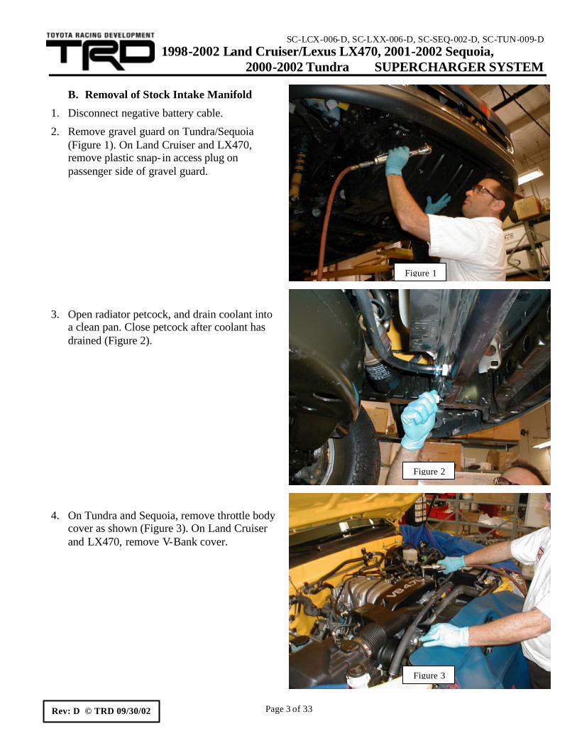
2. Make sure the engine has fully cooled before you begin.
3. To help with re-connecting the vacuum hoses, you should draw diagrams of your engine’s
vacuum hose routing before you disconnect anything. However, some of the vacuum connections on your stock air intake chamber may not be the same as those on the supercharger. Study and closely follow the installation instructions for correct vacuum hose connections.
4. The TRD supercharger system has been designed to reuse most of the original equipment
(OE) nuts and bolts. Therefore, as you remove them, keep them with their components or label them for location. This will assure a faster, easier installation.
Recommended Tools: Basic Tools:
Metric Socket Set Metric Allen-Head Set Metric Combination Wrench Set ½” Wide Masking Tape for Labeling Hardware and Parts A Clean Work Bench A Parts Tray Rags or Shop Towels Toyota Sealant # 08826-00100, # 00295-00102 or equivalent RTV Sealant
Safety Tools:
Safety Goggles
Special Tools:
Toyota Repair Manual: Available from Toyota, 800-622-2033
Accessories:
TRD boost gauge (not provided in supercharger kit)
SC-LCX-006-D, SC-LXX-006-D, SC-SEQ-002-D, SC-TUN-009-D 1998-2002 Land Cruiser/Lexus LX470, 2001-2002 Sequoia, 2000-2002 Tundra SUPERCHARGER SYSTEM
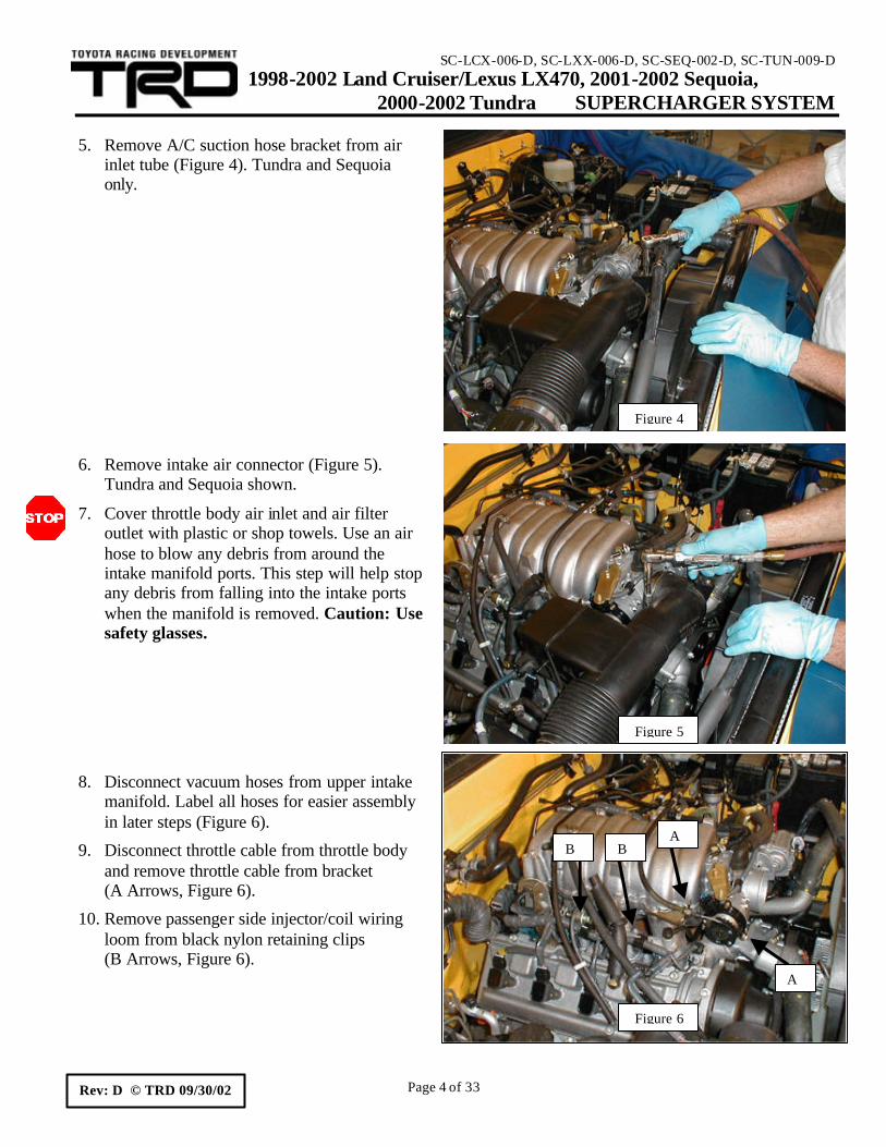
7. Cover throttle body air inlet and air filter outlet with plastic or shop towels. Use an air hose to blow any debris from around the intake manifold ports. This step will help stop any debris from falling into the intake ports when the manifold is removed. Caution: Use safety glasses.
8. Disconnect vacuum hoses from upper intake
manifold. Label all hoses for easier assembly in later steps (Figure 6).
9. Disconnect throttle cable from throttle body and remove throttle cable from bracket (A Arrows, Figure 6).
10. Remove passenger side injector/coil wiring loom from black nylon retaining clips (B Arrows, Figure 6).
Figure 4
Figure 5
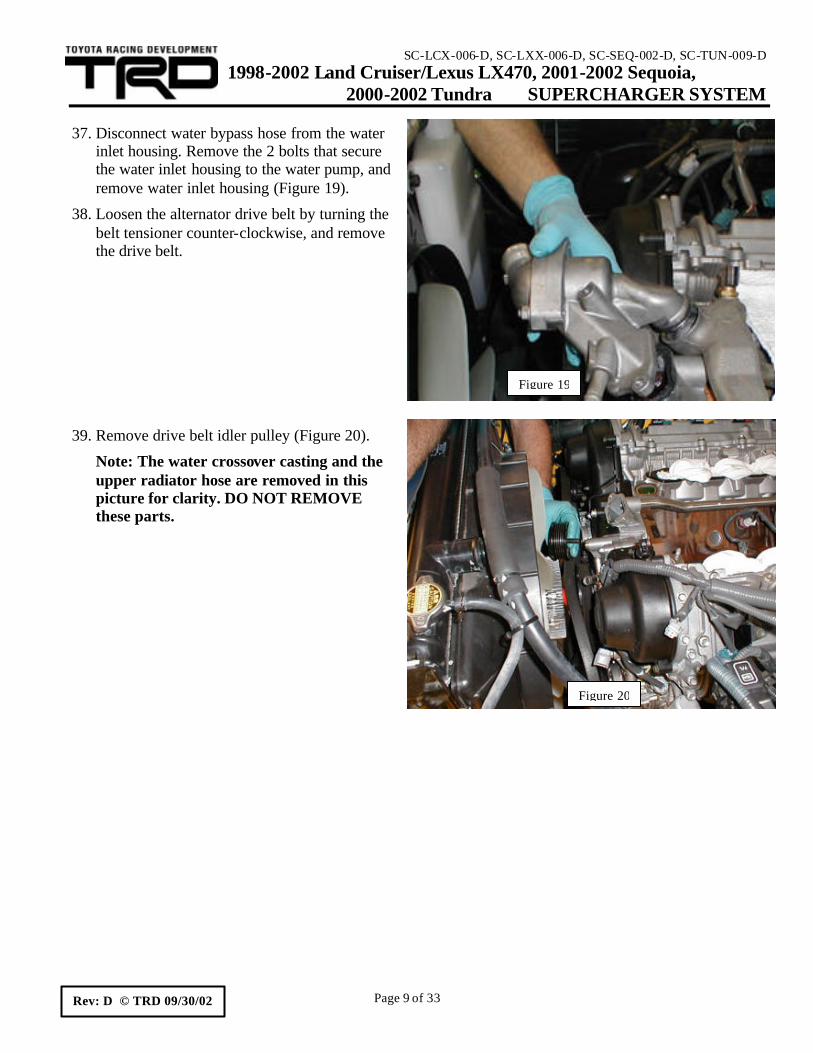
Figure 6
A
A B B
SC-LCX-006-D, SC-LXX-006-D, SC-SEQ-002-D, SC-TUN-009-D 1998-2002 Land Cruiser/Lexus LX470, 2001-2002 Sequoia, 2000-2002 Tundra SUPERCHARGER SYSTEM
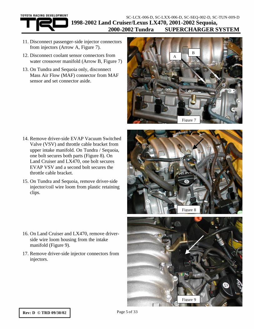
12. Disconnect coolant sensor connectors from water crossover manifold (Arrow B, Figure 7)
13. On Tundra and Sequoia only, disconnect Mass Air Flow (MAF) connector from MAF sensor and set connector aside.
14. Remove driver-side EVAP Vacuum Switched Valve (VSV) and throttle cable bracket from upper intake manifold. On Tundra / Sequoia, one bolt secures both parts (Figure 8). On Land Cruiser and LX470, one bolt secures EVAP VSV and a second bolt secures the throttle cable bracket.
15. On Tundra and Sequoia, remove driver-side injector/coil wire loom from plastic retaining clips.
16. On Land Cruiser and LX470, remove driver-side wire loom housing from the intake manifold (Figure 9).
17. Remove driver-side injector connectors from injectors.
Figure 7
A B
Figure 8
Figure 9
SC-LCX-006-D, SC-LXX-006-D, SC-SEQ-002-D, SC-TUN-009-D 1998-2002 Land Cruiser/Lexus LX470, 2001-2002 Sequoia, 2000-2002 Tundra SUPERCHARGER SYSTEM
19. Disconnect throttle motor and throttle position sensor (TPS) connectors (Figure 11).
20. Remove throttle body and disconnect water bypass hoses. Disconnect upper hose from throttle body and oil cooler pipe. Disconnect lower hose at water crossover fitting only.
21. On Land Cruiser and LX470, disconnect the ground strap from the engine- lifting hook on the driver-side of the engine.
22. Remove and replace the fuel cap to relieve pressure from the fuel system.
23. Place a shop towel under the fuel main hose at the fuel delivery pipe connection point. Remove the pulsation damper, upper and lower gaskets, and set the fuel main hose aside (Figure 12). Caution: Fuel spillage will occur. Retain the gaskets for reuse.
24. Remove OE rubber fuel return hose from fuel pressure regulator on passenger-side of engine.
Figure 12
Figure 10
Figure 11
SC-LCX-006-D, SC-LXX-006-D, SC-SEQ-002-D, SC-TUN-009-D 1998-2002 Land Cruiser/Lexus LX470, 2001-2002 Sequoia, 2000-2002 Tundra SUPERCHARGER SYSTEM
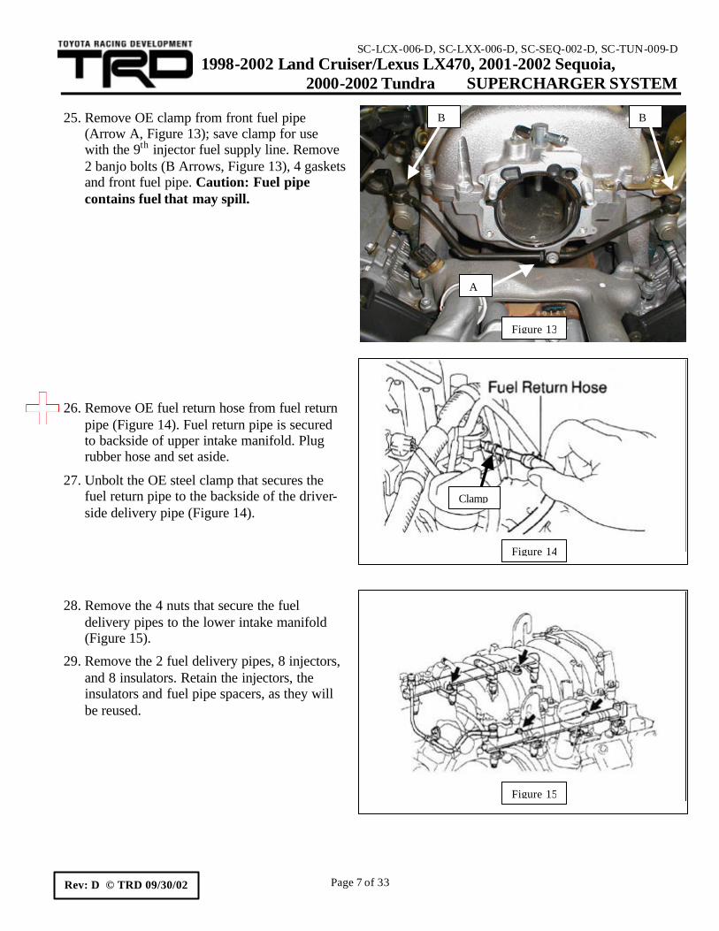
(Arrow A, Figure 13); save clamp for use with the 9th injector fuel supply line. Remove 2 banjo bolts (B Arrows, Figure 13), 4 gaskets and front fuel pipe. Caution: Fuel pipe contains fuel that may spill.
26. Remove OE fuel return hose from fuel return pipe (Figure 14). Fuel return pipe is secured to backside of upper intake manifold. Plug rubber hose and set aside.
27. Unbolt the OE steel clamp that secures the fuel return pipe to the backside of the driver-side delivery pipe (Figure 14).
28. Remove the 4 nuts that secure the fuel delivery pipes to the lower intake manifold (Figure 15).
29. Remove the 2 fuel delivery pipes, 8 injectors, and 8 insulators. Retain the injectors, the insulators and fuel pipe spacers, as they will be reused.
Figure 15
Figure 13
A
B B
Figure 14
Clamp
SC-LCX-006-D, SC-LXX-006-D, SC-SEQ-002-D, SC-TUN-009-D 1998-2002 Land Cruiser/Lexus LX470, 2001-2002 Sequoia, 2000-2002 Tundra SUPERCHARGER SYSTEM
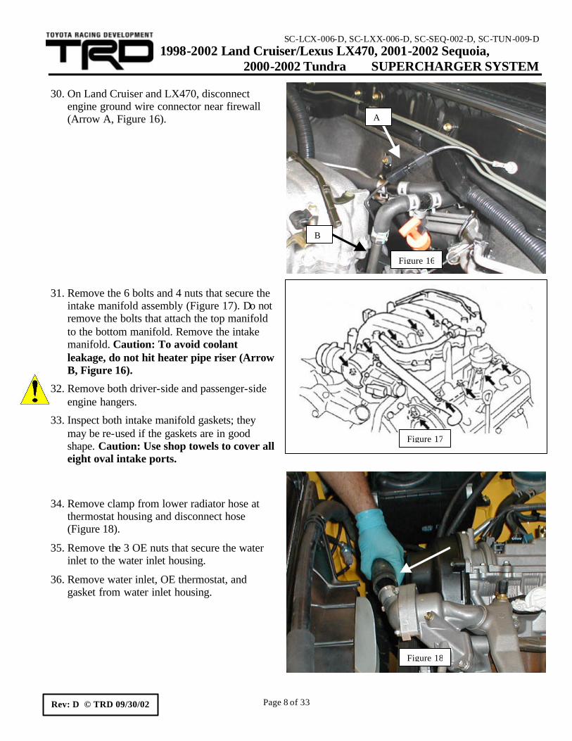
engine ground wire connector near firewall (Arrow A, Figure 16).
31. Remove the 6 bolts and 4 nuts that secure the
intake manifold assembly (Figure 17). Do not remove the bolts that attach the top manifold to the bottom manifold. Remove the intake manifold. Caution: To avoid coolant leakage, do not hit heater pipe riser (Arrow B, Figure 16).
32. Remove both driver-side and passenger-side engine hangers.
33. Inspect both intake manifold gaskets; they may be re-used if the gaskets are in good shape. Caution: Use shop towels to cover all eight oval intake ports.
34. Remove clamp from lower radiator hose at
thermostat housing and disconnect hose (Figure 18).
35. Remove the 3 OE nuts that secure the water inlet to the water inlet housing.
36. Remove water inlet, OE thermostat, and gasket from water inlet housing.
Figure 17
Figure 16
A
B
Figure 18
SC-LCX-006-D, SC-LXX-006-D, SC-SEQ-002-D, SC-TUN-009-D 1998-2002 Land Cruiser/Lexus LX470, 2001-2002 Sequoia, 2000-2002 Tundra SUPERCHARGER SYSTEM
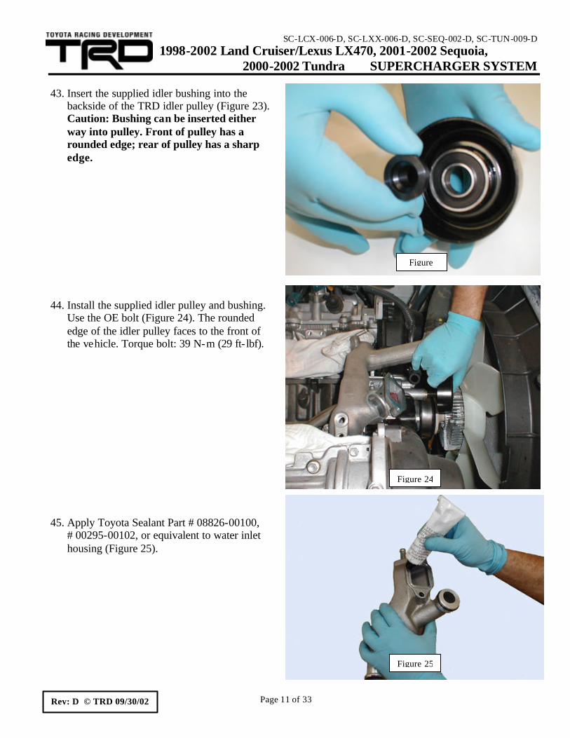
backside of the TRD idler pulley (Figure 23). Caution: Bushing can be inserted either way into pulley. Front of pulley has a rounded edge; rear of pulley has a sharp edge.
44. Install the supplied idler pulley and bushing. Use the OE bolt (Figure 24). The rounded edge of the idler pulley faces to the front of the vehicle. Torque bolt: 39 N-m (29 ft- lbf).
45. Apply Toyota Sealant Part # 08826-00100,
# 00295-00102, or equivalent to water inlet housing (Figure 25).
Figure
Figure 24
Figure 25
SC-LCX-006-D, SC-LXX-006-D, SC-SEQ-002-D, SC-TUN-009-D 1998-2002 Land Cruiser/Lexus LX470, 2001-2002 Sequoia, 2000-2002 Tundra SUPERCHARGER SYSTEM
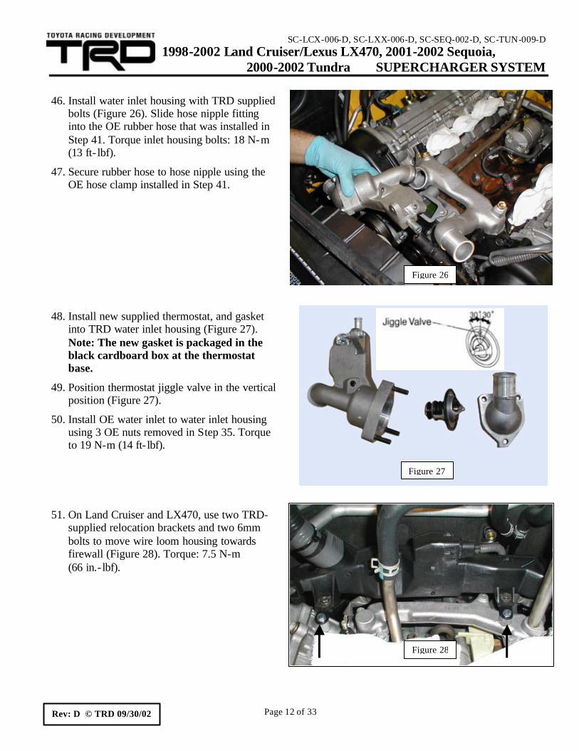
46. Install water inlet housing with TRD supplied bolts (Figure 26). Slide hose nipple fitting into the OE rubber hose that was installed in Step 41. Torque inlet housing bolts: 18 N-m (13 ft- lbf).
47. Secure rubber hose to hose nipple using the OE hose clamp installed in Step 41.
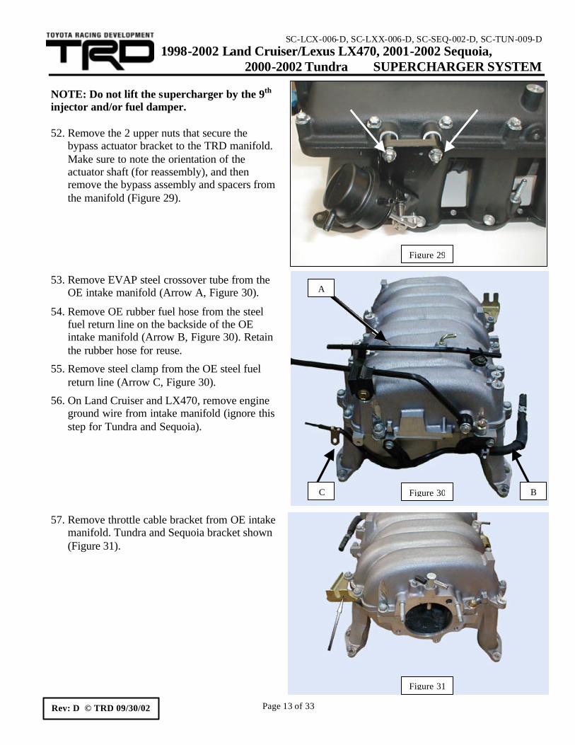
48. Install new supplied thermostat, and gasket into TRD water inlet housing (Figure 27). Note: The new gasket is packaged in the black cardboard box at the thermostat base.
49. Position thermostat jiggle valve in the vertical position (Figure 27).
50. Install OE water inlet to water inlet housing using 3 OE nuts removed in Step 35. Torque to 19 N-m (14 ft- lbf).
51. On Land Cruiser and LX470, use two TRD-supplied relocation brackets and two 6mm bolts to move wire loom housing towards firewall (Figure 28). Torque: 7.5 N-m (66 in.- lbf).
Figure 26
Figure 28
Figure 27
SC-LCX-006-D, SC-LXX-006-D, SC-SEQ-002-D, SC-TUN-009-D 1998-2002 Land Cruiser/Lexus LX470, 2001-2002 Sequoia, 2000-2002 Tundra SUPERCHARGER SYSTEM
NOTE: Do not lift the supercharger by the 9th injector and/or fuel damper. 52. Remove the 2 upper nuts that secure the
bypass actuator bracket to the TRD manifold. Make sure to note the orientation of the actuator shaft (for reassembly), and then remove the bypass assembly and spacers from the manifold (Figure 29).
53. Remove EVAP steel crossover tube from the OE intake manifold (Arrow A, Figure 30).
54. Remove OE rubber fuel hose from the steel fuel return line on the backside of the OE intake manifold (Arrow B, Figure 30). Retain the rubber hose for reuse.
55. Remove steel clamp from the OE steel fuel return line (Arrow C, Figure 30).
56. On Land Cruiser and LX470, remove engine ground wire from intake manifold (ignore this step for Tundra and Sequoia).
57. Remove throttle cable bracket from OE intake manifold. Tundra and Sequoia bracket shown (Figure 31).
Figure 31
Figure 29
Figure 30 B C
A
SC-LCX-006-D, SC-LXX-006-D, SC-SEQ-002-D, SC-TUN-009-D 1998-2002 Land Cruiser/Lexus LX470, 2001-2002 Sequoia, 2000-2002 Tundra SUPERCHARGER SYSTEM
NPT plug and install 1/8” NPT x 3/8” barb fitting into supercharger plenum (Figure 32).
59. Remove OE throttle cable support bracket from OE intake manifold.
60. On Tundra and Sequoia, install the OE throttle cable support bracket (Arrow A, Figure 33) onto the TRD supercharger manifold using the OE 8mm bolt. On Land Cruiser/LX470, the OE bracket has a 6mm hole. Drill the bracket hole to 8mm or 21/64.
61. Install the Land Cruiser/LX470 throttle cable support bracket using the supplied 25.4mm (1.0 inch) spacer, and supplied 8mm bolt (Arrow B, Figure 33).
62. Insert the OE rubber fuel return hose removed in Step 54 through the Adel clamp mounted on the passenger-side of the TRD manifold (Figure 34).
Figure 32
Figure 33
A
B
Figure 34
SC-LCX-006-D, SC-LXX-006-D, SC-SEQ-002-D, SC-TUN-009-D 1998-2002 Land Cruiser/Lexus LX470, 2001-2002 Sequoia, 2000-2002 Tundra SUPERCHARGER SYSTEM
supercharger inlet elbow (Arrow A, Figure 35), loosen the passenger-side bolt that secures the 9th injector fuel rail and rotate the assembly. Remove the 8mm bolt.
64. Install the supplied steel fuel return line to the inlet elbow. Connect the OE rubber fuel return hose to the steel line (Arrow B, Figure 35). Re-use the OE hose clamp. Torque the 8mm bolt to 21 N-m (15 ft- lbf).
65. Install the supplied nylon wrap over the passenger-side heater hose (Figure 36). Install wrap just above the OE heater hose clamp. Caution: Position OE clamp as shown.
66. Re- install EVAP steel crossover line removed in Step 53 (Arrow A, Figure 37). On Land Cruiser/LX470 only, secure engine ground wire (removed in Step 56) between EVAP line bracket and intake manifold (Arrow B, Figure 37).
67. Remove the shop towels that are covering the intake gaskets and ports on the engine.
68. Check the TRD supercharger manifold base where it will contact the intake manifold gaskets. Clean supercharger manifold base if necessary.
Figure 36
Figure 37
A
B
A
B
Figure 35
SC-LCX-006-D, SC-LXX-006-D, SC-SEQ-002-D, SC-TUN-009-D 1998-2002 Land Cruiser/Lexus LX470, 2001-2002 Sequoia, 2000-2002 Tundra SUPERCHARGER SYSTEM
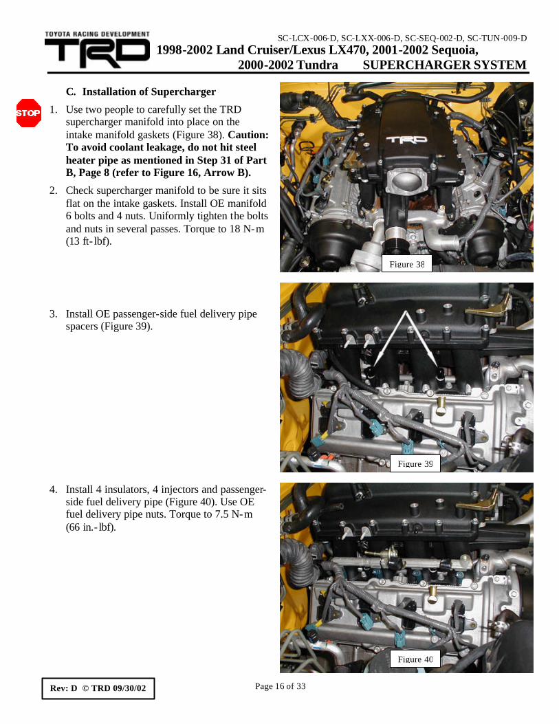
1. Use two people to carefully set the TRD supercharger manifold into place on the intake manifold gaskets (Figure 38). Caution: To avoid coolant leakage, do not hit steel heater pipe as mentioned in Step 31 of Part B, Page 8 (refer to Figure 16, Arrow B).
2. Check supercharger manifold to be sure it sits flat on the intake gaskets. Install OE manifold 6 bolts and 4 nuts. Uniformly tighten the bolts and nuts in several passes. Torque to 18 N-m (13 ft- lbf).
regulator. Use OE hose clamp to secure hose (Figure 41). Be sure to position the hose clamp with the ears (tangs) up.
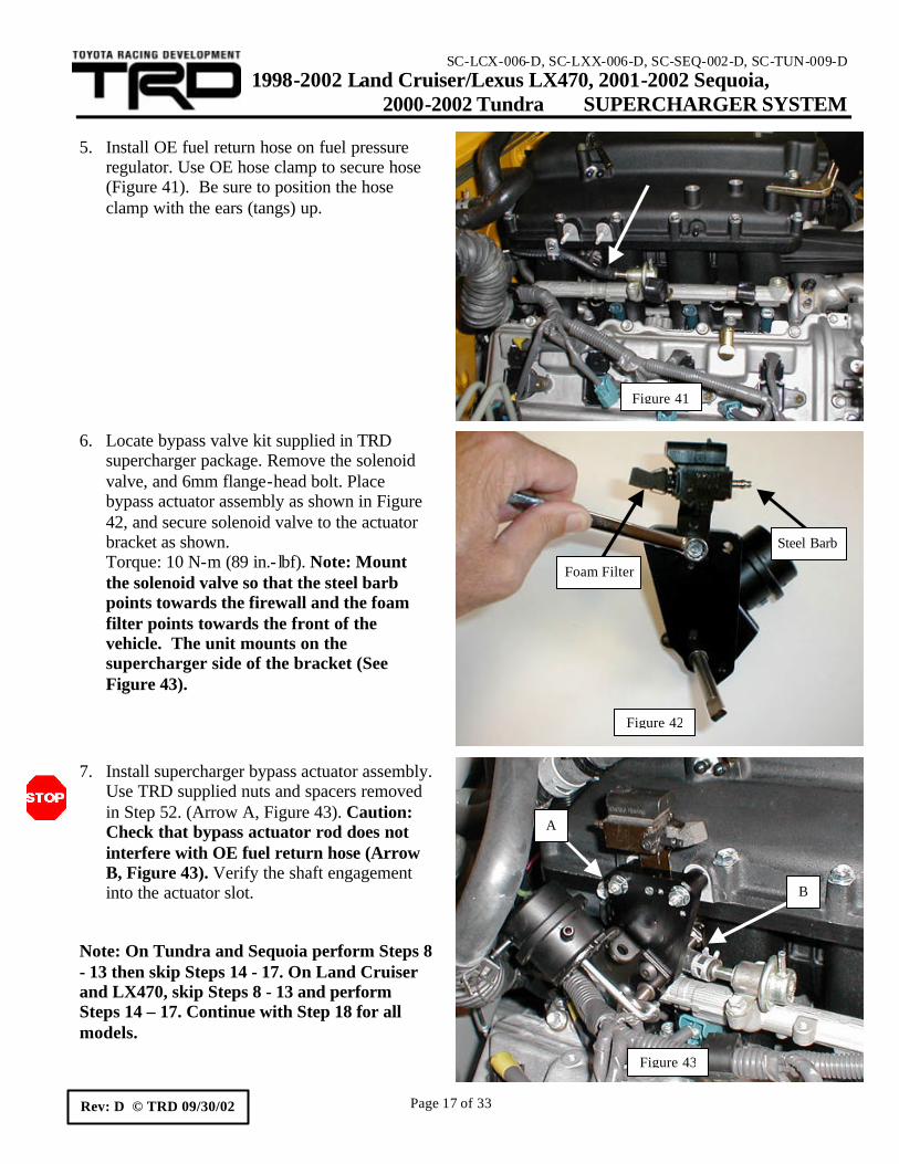
6. Locate bypass valve kit supplied in TRD supercharger package. Remove the solenoid valve, and 6mm flange-head bolt. Place bypass actuator assembly as shown in Figure 42, and secure solenoid valve to the actuator bracket as shown. Torque: 10 N-m (89 in.- lbf). Note: Mount the solenoid valve so that the steel barb points towards the firewall and the foam filter points towards the front of the vehicle. The unit mounts on the supercharger side of the bracket (See Figure 43).
7. Install supercharger bypass actuator assembly. Use TRD supplied nuts and spacers removed in Step 52. (Arrow A, Figure 43). Caution: Check that bypass actuator rod does not interfere with OE fuel return hose (Arrow B, Figure 43). Verify the shaft engagement into the actuator slot.
Note: On Tundra and Sequoia perform Steps 8 - 13 then skip Steps 14 - 17. On Land Cruiser and LX470, skip Steps 8 - 13 and perform Steps 14 – 17. Continue with Step 18 for all models.
Figure 41
Figure 43
A
B
Figure 42
Foam Filter
Steel Barb
SC-LCX-006-D, SC-LXX-006-D, SC-SEQ-002-D, SC-TUN-009-D 1998-2002 Land Cruiser/Lexus LX470, 2001-2002 Sequoia, 2000-2002 Tundra SUPERCHARGER SYSTEM
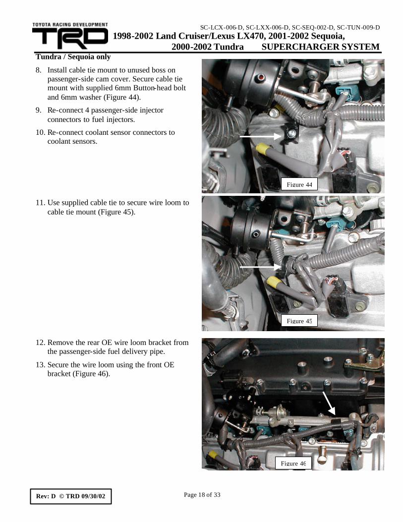
8. Install cable tie mount to unused boss on passenger-side cam cover. Secure cable tie mount with supplied 6mm Button-head bolt and 6mm washer (Figure 44).
9. Re-connect 4 passenger-side injector connectors to fuel injectors.
10. Re-connect coolant sensor connectors to coolant sensors.
11. Use supplied cable tie to secure wire loom to
cable tie mount (Figure 45).
12. Remove the rear OE wire loom bracket from the passenger-side fuel delivery pipe.
13. Secure the wire loom using the front OE bracket (Figure 46).
Figure 44
Figure 45
Figure 46
SC-LCX-006-D, SC-LXX-006-D, SC-SEQ-002-D, SC-TUN-009-D 1998-2002 Land Cruiser/Lexus LX470, 2001-2002 Sequoia, 2000-2002 Tundra SUPERCHARGER SYSTEM
14. Use supplied #16 Adel clamp to secure wire loom to bypass actuator bracket. (Figure 47). Torque bolt to 18 N-m (13 ft- lbf).
15. Remove the 2 OE wire loom brackets from the passenger-side fuel delivery pipe.
16. Turn the brackets upside down and re-attach to the fuel delivery pipe using the OE bolts (Figure 48).
17. Secure wire loom using the OE brackets installed in the previous step.
All models
18. Check the passenger-side wire loom clearance to bypass actuator assembly, linkage and rod. The wire loom should clear all bypass actuator components. If the wire loom is too close to any bypass actuator components, then re-check steps 8 – 13 for Tundra/Sequoia, and steps 14 – 17 for Land Cruiser/LX470. Additional cable ties may be used to secure the wire loom away from the bypass actuator assembly.
Figure 48
Figure 47
SC-LCX-006-D, SC-LXX-006-D, SC-SEQ-002-D, SC-TUN-009-D 1998-2002 Land Cruiser/Lexus LX470, 2001-2002 Sequoia, 2000-2002 Tundra SUPERCHARGER SYSTEM
20. Install 4 insulators, 4 injectors and driver-side fuel delivery pipe (Figure 49 and 50). Use OE fuel delivery pipe nuts. Torque to 7.5 N-m (66 in.- lbf).
21. Reconnect the driver-side injector wires to the fuel injectors.
22. Use the OE clamp removed in Step 55 (Part B, Page 13) to secure the TRD fuel return line to the rear of the driver-side fuel delivery pipe (Arrow A, Figure 50). Torque OE bolt to 7.5 N-m (66in.- lbf).
23. Re-connect the OE fuel return hose to the TRD return line using the OE hose clamp (Figure 50).
24. Re- install the lower gasket, fuel main hose, upper gasket and fuel pulsation damper. Use SST # 09612-24014 (09617-24011) to tighten damper. Torque the damper to 33 N-m (24 ft-lbf) for use with SST, 39 N-m (29 ft-lbf) without SST.
25. Position the OE front fuel pipe bracket
removed in Step 25 (Part B, Page 7) onto the supplied 9th injector fuel delivery line. Position the bracket 10 ½” from the banjo centerline along the longest straight section of the tube (Figure 51).
Figure 49
Figure 51
OE Bracket
A
Figure 50
SC-LCX-006-D, SC-LXX-006-D, SC-SEQ-002-D, SC-TUN-009-D 1998-2002 Land Cruiser/Lexus LX470, 2001-2002 Sequoia, 2000-2002 Tundra SUPERCHARGER SYSTEM
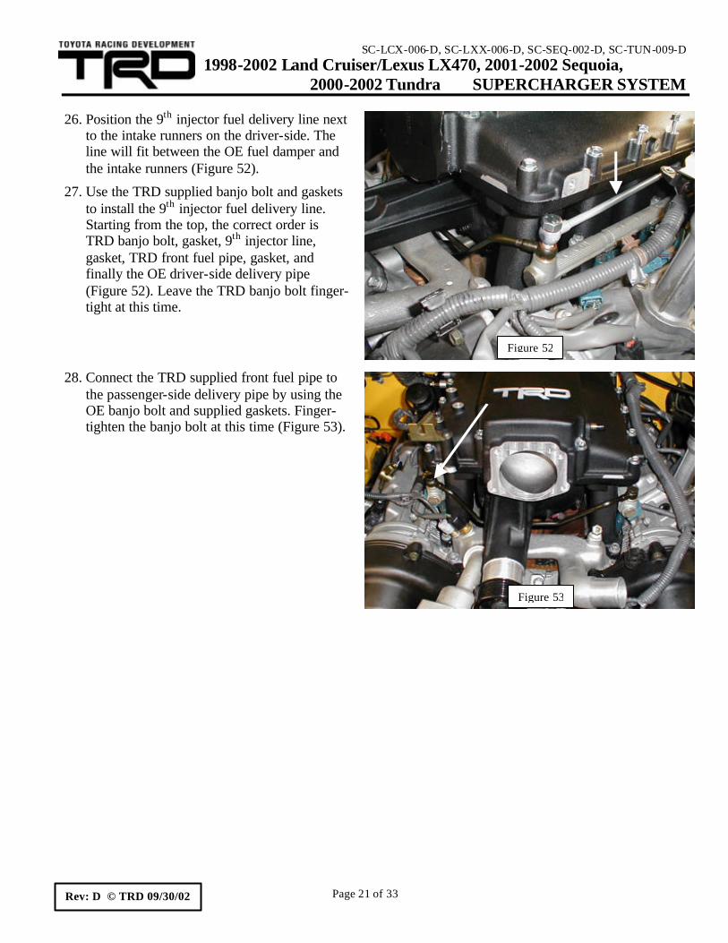
26. Position the 9th injector fuel delivery line next
to the intake runners on the driver-side. The line will fit between the OE fuel damper and the intake runners (Figure 52).
27. Use the TRD supplied banjo bolt and gaskets to install the 9th injector fuel delivery line. Starting from the top, the correct order is TRD banjo bolt, gasket, 9th injector line, gasket, TRD front fuel pipe, gasket, and finally the OE driver-side delivery pipe (Figure 52). Leave the TRD banjo bolt finger-tight at this time.
28. Connect the TRD supplied front fuel pipe to the passenger-side delivery pipe by using the OE banjo bolt and supplied gaskets. Finger-tighten the banjo bolt at this time (Figure 53).
Figure 52
Figure 53
SC-LCX-006-D, SC-LXX-006-D, SC-SEQ-002-D, SC-TUN-009-D 1998-2002 Land Cruiser/Lexus LX470, 2001-2002 Sequoia, 2000-2002 Tundra SUPERCHARGER SYSTEM
gaskets to secure the 9th injector fuel delivery line to the TRD fuel rail on the backside of the intake manifold (Figure 54). Leave the banjo bolt finger-tight at this time.
30. Use the OE 6mm fuel pipe bolt to secure the 9th injector fuel line bracket to the mounting hole on the driver-side of the TRD intake manifold (Arrow A, Figure 55). Torque bolt: 7.5 N-m (66 in.- lbf)
31. Check the routing of the 9th injector fuel delivery line. It should be centered between the # 7 intake runner and the OE fuel damper (Arrow B, Figure 55). The line should not touch any components.
32. Torque all three fuel- line banjo fittings to 39 N-m (29 ft- lbf).
33. Install the supercharger nose support bracket. Adjust the nose support bracket to fit snug against the supercharger nose. Secure the bracket with the supplied 8mm flange-head bolt and flange-head nut (Figure 56). Torque the fasteners to 18 N-m (13 ft- lbf).
Figure 54
Figure 55
A B
Figure 56
SC-LCX-006-D, SC-LXX-006-D, SC-SEQ-002-D, SC-TUN-009-D 1998-2002 Land Cruiser/Lexus LX470, 2001-2002 Sequoia, 2000-2002 Tundra SUPERCHARGER SYSTEM
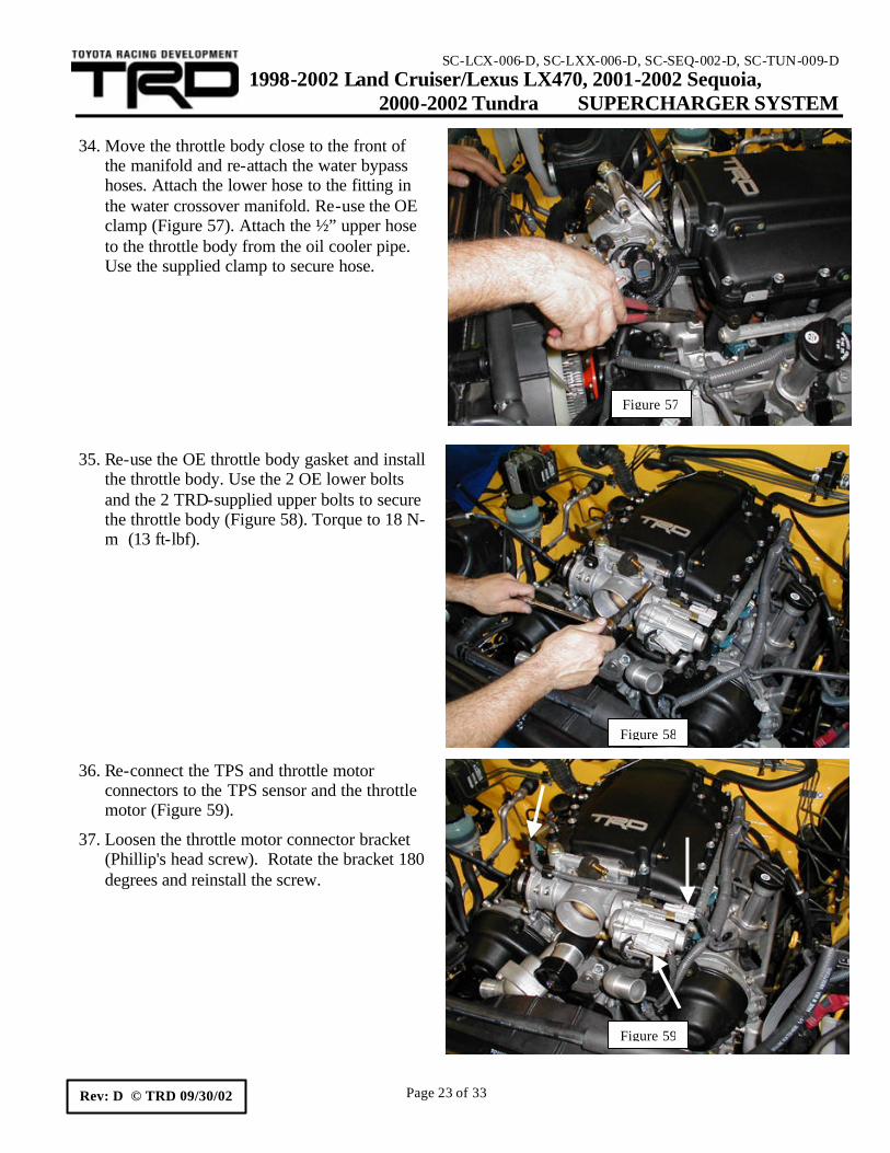
the manifold and re-attach the water bypass hoses. Attach the lower hose to the fitting in the water crossover manifold. Re-use the OE clamp (Figure 57). Attach the ½” upper hose to the throttle body from the oil cooler pipe. Use the supplied clamp to secure hose.
35. Re-use the OE throttle body gasket and install
the throttle body. Use the 2 OE lower bolts and the 2 TRD-supplied upper bolts to secure the throttle body (Figure 58). Torque to 18 N-m (13 ft-lbf).
36. Re-connect the TPS and throttle motor connectors to the TPS sensor and the throttle motor (Figure 59).
37. Loosen the throttle motor connector bracket (Phillip's head screw). Rotate the bracket 180 degrees and reinstall the screw.
Figure 57
Figure 58
Figure 59
SC-LCX-006-D, SC-LXX-006-D, SC-SEQ-002-D, SC-TUN-009-D 1998-2002 Land Cruiser/Lexus LX470, 2001-2002 Sequoia, 2000-2002 Tundra SUPERCHARGER SYSTEM
39. Locate the A/C compressor on the driver's-side of the engine and remove both the OE flange-head nut (Arrow A, Figure 61) and the 8mm bolt (Arrow B, Figure 61).
40. Mount the TRD-supplied idler pulley bracket using the OE flange-head nut (Arrow A, Figure 62) and the supplied 8mm flange-head bolt (Arrow B, Figure 62). Torque bolt to 16 N-m (12 ft- lbf) and the nut 32 N-m (24 ft-lbf).
Figure 61
A
B
Figure 60
Figure 62
B
A
SC-LCX-006-D, SC-LXX-006-D, SC-SEQ-002-D, SC-TUN-009-D 1998-2002 Land Cruiser/Lexus LX470, 2001-2002 Sequoia, 2000-2002 Tundra SUPERCHARGER SYSTEM
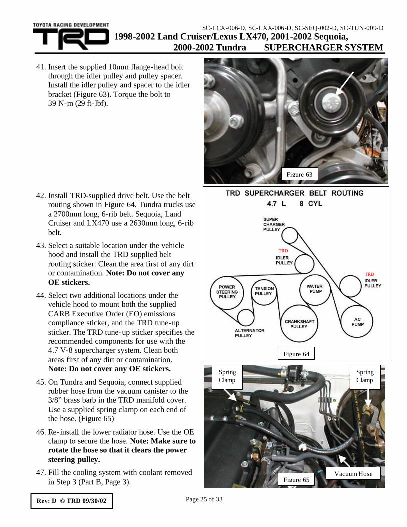
through the idler pulley and pulley spacer. Install the idler pulley and spacer to the idler bracket (Figure 63). Torque the bolt to 39 N-m (29 ft- lbf).
42. Install TRD-supplied drive belt. Use the belt routing shown in Figure 64. Tundra trucks use a 2700mm long, 6-rib belt. Sequoia, Land Cruiser and LX470 use a 2630mm long, 6-rib belt.
43. Select a suitable location under the vehicle hood and install the TRD supplied belt routing sticker. Clean the area first of any dirt or contamination. Note: Do not cover any OE stickers.
44. Select two additional locations under the vehicle hood to mount both the supplied CARB Executive Order (EO) emissions compliance sticker, and the TRD tune-up sticker. The TRD tune-up sticker specifies the recommended components for use with the 4.7 V-8 supercharger system. Clean both areas first of any dirt or contamination. Note: Do not cover any OE stickers.
45. On Tundra and Sequoia, connect supplied rubber hose from the vacuum canister to the 3/8” brass barb in the TRD manifold cover. Use a supplied spring clamp on each end of the hose. (Figure 65)
46. Re- install the lower radiator hose. Use the OE clamp to secure the hose. Note: Make sure to rotate the hose so that it clears the power steering pulley.
47. Fill the cooling system with coolant removed in Step 3 (Part B, Page 3).
Figure 64
Figure 63
Figure 65Vacuum Hose
Spring Clamp
Spring Clamp
SC-LCX-006-D, SC-LXX-006-D, SC-SEQ-002-D, SC-TUN-009-D 1998-2002 Land Cruiser/Lexus LX470, 2001-2002 Sequoia, 2000-2002 Tundra SUPERCHARGER SYSTEM
Tundra/Sequoia. On Land Cruiser and LX470, re- install plastic snap- in access plug in gravel guard (Passenger Side).
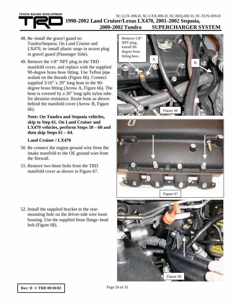
49. Remove the 1/8” NPT plug in the TRD manifold cover, and replace with the supplied 90-degree brass hose fitting. Use Teflon pipe sealant on the threads (Figure 66). Connect supplied 3/16” x 29” long hose to the 90-degree brass fitting (Arrow A, Figure 66). The hose is covered by a 26” long split nylon tube for abrasion resistance. Route hose as shown behind the manifold cover (Arrow B, Figure 66).
Note: On Tundra and Sequoia vehicles, skip to Step 61. On Land Cruiser and LX470 vehicles, perform Steps 50 – 60 and then skip Steps 61 – 64.
Land Cruiser / LX470
50. Re-connect the engine ground wire from the intake manifold to the OE ground wire from the firewall.
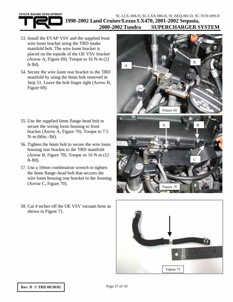
51. Remove two 6mm bolts from the TRD manifold cover as shown in Figure 67.
52. Install the supplied bracket to the rear-mounting hole on the driver-side wire loom housing. Use the supplied 6mm flange-head bolt (Figure 68).
wire loom bracket using the TRD intake manifold bolt. The wire loom bracket is placed on the topside of the OE VSV bracket (Arrow A, Figure 69). Torque to 16 N-m (12 ft- lbf).
54. Secure the wire loom rear bracket to the TRD manifold by using the 6mm bolt removed in Step 51. Leave the bolt finger tight (Arrow B, Figure 69).
55. Use the supplied 6mm flange-head bolt to secure the wiring loom housing to front bracket (Arrow A, Figure 70). Torque to 7.5 N-m (66in.- lbf).
56. Tighten the 6mm bolt to secure the wire loom housing rear bracket to the TRD manifold (Arrow B, Figure 70). Torque to 16 N-m (12 ft- lbf).
57. Use a 10mm combination wrench to tighten the 6mm flange-head bolt that secures the wire loom housing rear bracket to the housing (Arrow C, Figure 70).
58. Cut 4 inches off the OE VSV vacuum hose as shown in Figure 71.
Figure 69
A B
Figure 70
A B
C
Figure 71
SC-LCX-006-D, SC-LXX-006-D, SC-SEQ-002-D, SC-TUN-009-D 1998-2002 Land Cruiser/Lexus LX470, 2001-2002 Sequoia, 2000-2002 Tundra SUPERCHARGER SYSTEM
VSV and the 3/8” hose nipple on the TRD manifold. Use OE clamps to secure the hose (Figure 72).
60. Re-connect the VSV electrical connector to the VSV (Figure 72).
Tundra / Sequoia
61. Remove one 6mm bolt in the TRD manifold. Bolt location shown in Figure 73, Arrow A.
62. Secure the EVAP VSV with the 6mm bolt removed in the previous step. Torque to 16 N-m (12 ft- lbf). Complete installation shown in Figure 73.
63. Connect the EVAP VSV vacuum hose to the VSV and the 3/8” hose nipple on the TRD manifold. Use OE clamps to secure the hose (B Arrows, Figure 73).
64. Re-connect the VSV electrical connector to the VSV (Arrow C, Figure 73).
All models
65. Re-connect the EVAP canister vacuum hose removed in Part B, Step 8 on Page 4 (Arrow D, Figure 73).
66. Re- install the PCV valve hose (Arrow E, Figure 73).
67. Install throttle cable bracket to the TRD intake manifold cover using the supplied 8mm bolts. Use A Arrows location for Tundra/Sequoia. Use B Arrows location for Land Cruiser/LX470. (Figure 74). Torque: 18 N-m (13 ft- lbf).
68. Re- install throttle cable into bracket, and connect cable to throttle body. (Figure 74).
Figure 72
Figure 73
A
B
B C
D
E
Figure 74
A
A
B B
SC-LCX-006-D, SC-LXX-006-D, SC-SEQ-002-D, SC-TUN-009-D 1998-2002 Land Cruiser/Lexus LX470, 2001-2002 Sequoia, 2000-2002 Tundra SUPERCHARGER SYSTEM
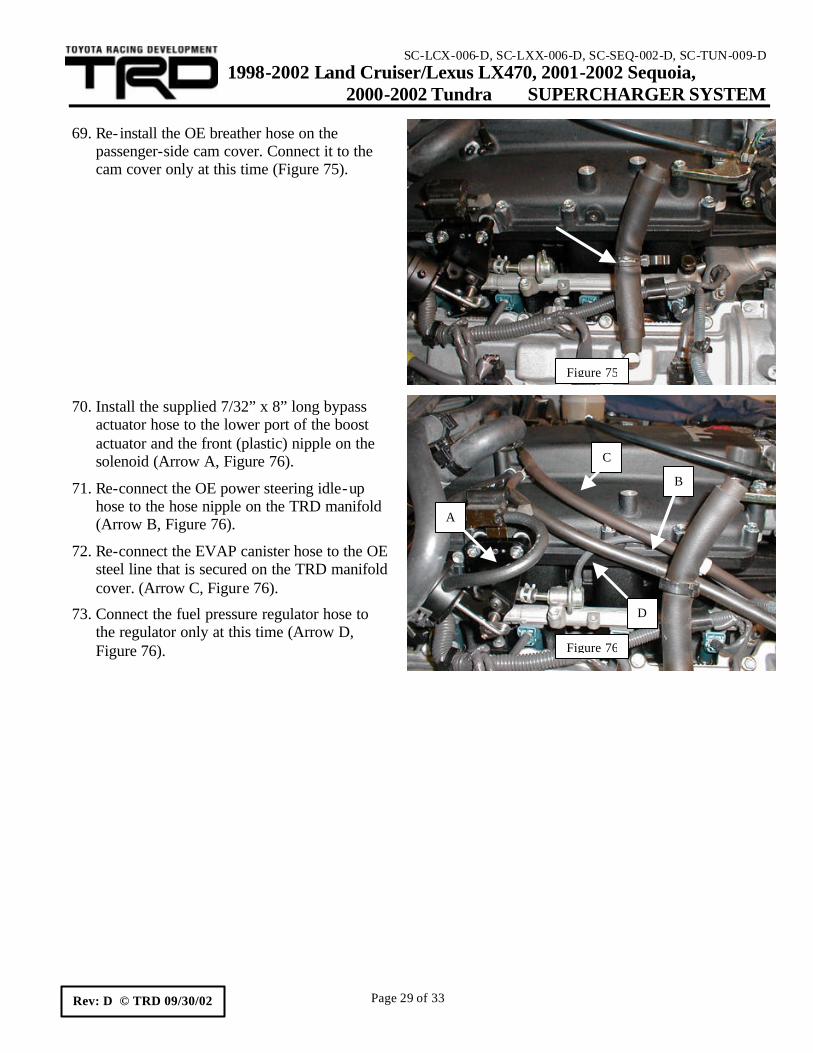
passenger-side cam cover. Connect it to the cam cover only at this time (Figure 75).
70. Install the supplied 7/32” x 8” long bypass actuator hose to the lower port of the boost actuator and the front (plastic) nipple on the solenoid (Arrow A, Figure 76).
71. Re-connect the OE power steering idle-up hose to the hose nipple on the TRD manifold (Arrow B, Figure 76).
72. Re-connect the EVAP canister hose to the OE steel line that is secured on the TRD manifold cover. (Arrow C, Figure 76).
73. Connect the fuel pressure regulator hose to the regulator only at this time (Arrow D, Figure 76).
Figure 75
Figure 76
A
B
C
D
SC-LCX-006-D, SC-LXX-006-D, SC-SEQ-002-D, SC-TUN-009-D 1998-2002 Land Cruiser/Lexus LX470, 2001-2002 Sequoia, 2000-2002 Tundra SUPERCHARGER SYSTEM
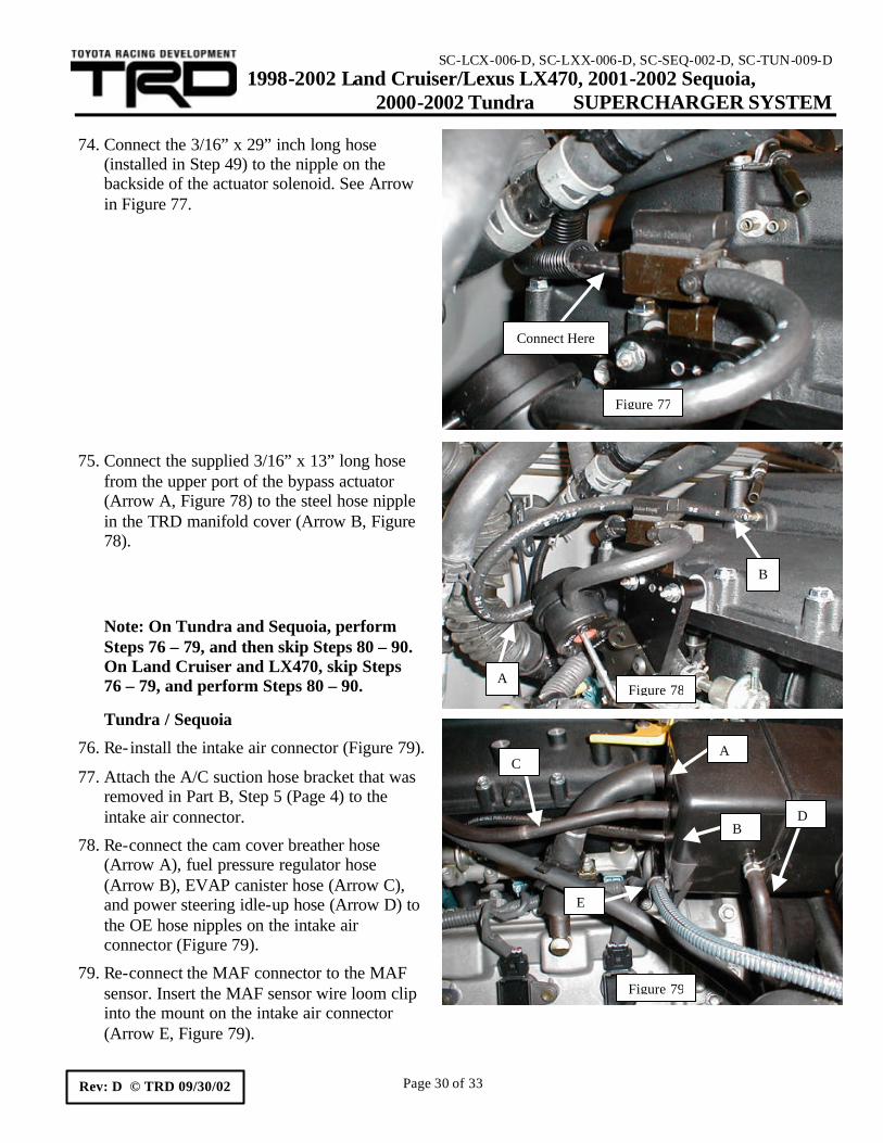
(installed in Step 49) to the nipple on the backside of the actuator solenoid. See Arrow in Figure 77.
75. Connect the supplied 3/16” x 13” long hose from the upper port of the bypass actuator (Arrow A, Figure 78) to the steel hose nipple in the TRD manifold cover (Arrow B, Figure 78).
Note: On Tundra and Sequoia, perform Steps 76 – 79, and then skip Steps 80 – 90. On Land Cruiser and LX470, skip Steps 76 – 79, and perform Steps 80 – 90.
Tundra / Sequoia
76. Re- install the intake air connector (Figure 79).
77. Attach the A/C suction hose bracket that was removed in Part B, Step 5 (Page 4) to the intake air connector.
78. Re-connect the cam cover breather hose (Arrow A), fuel pressure regulator hose (Arrow B), EVAP canister hose (Arrow C), and power steering idle-up hose (Arrow D) to the OE hose nipples on the intake air connector (Figure 79).
79. Re-connect the MAF connector to the MAF sensor. Insert the MAF sensor wire loom clip into the mount on the intake air connector (Arrow E, Figure 79).
Figure 79
A
B D
C
E
Figure 77
Connect Here
Figure 78A
B
SC-LCX-006-D, SC-LXX-006-D, SC-SEQ-002-D, SC-TUN-009-D 1998-2002 Land Cruiser/Lexus LX470, 2001-2002 Sequoia, 2000-2002 Tundra SUPERCHARGER SYSTEM
80. Use a hacksaw or band saw to cut the OE Land Cruiser/LX470 intake air connector into two pieces. Cut connector in the middle of the straight section (Figure 80).
81. Cut an additional 10mm (0.400") off the OE intake air connector (Figure 81). De-burr both halves of the intake air connector.
82. Connect the OE intake air connector to the air filter housing. Do not tighten the clamp at this time.
83. Position the two supplied aluminum spacers on the passenger-side cam cover (Figure 82). The spacers will raise the intake air connector off the cam cover. The tall spacer is used for the rear mount. The short spacer is used for the front mount.
Figure 81
Figure 82
Figure 80
SC-LCX-006-D, SC-LXX-006-D, SC-SEQ-002-D, SC-TUN-009-D 1998-2002 Land Cruiser/Lexus LX470, 2001-2002 Sequoia, 2000-2002 Tundra SUPERCHARGER SYSTEM
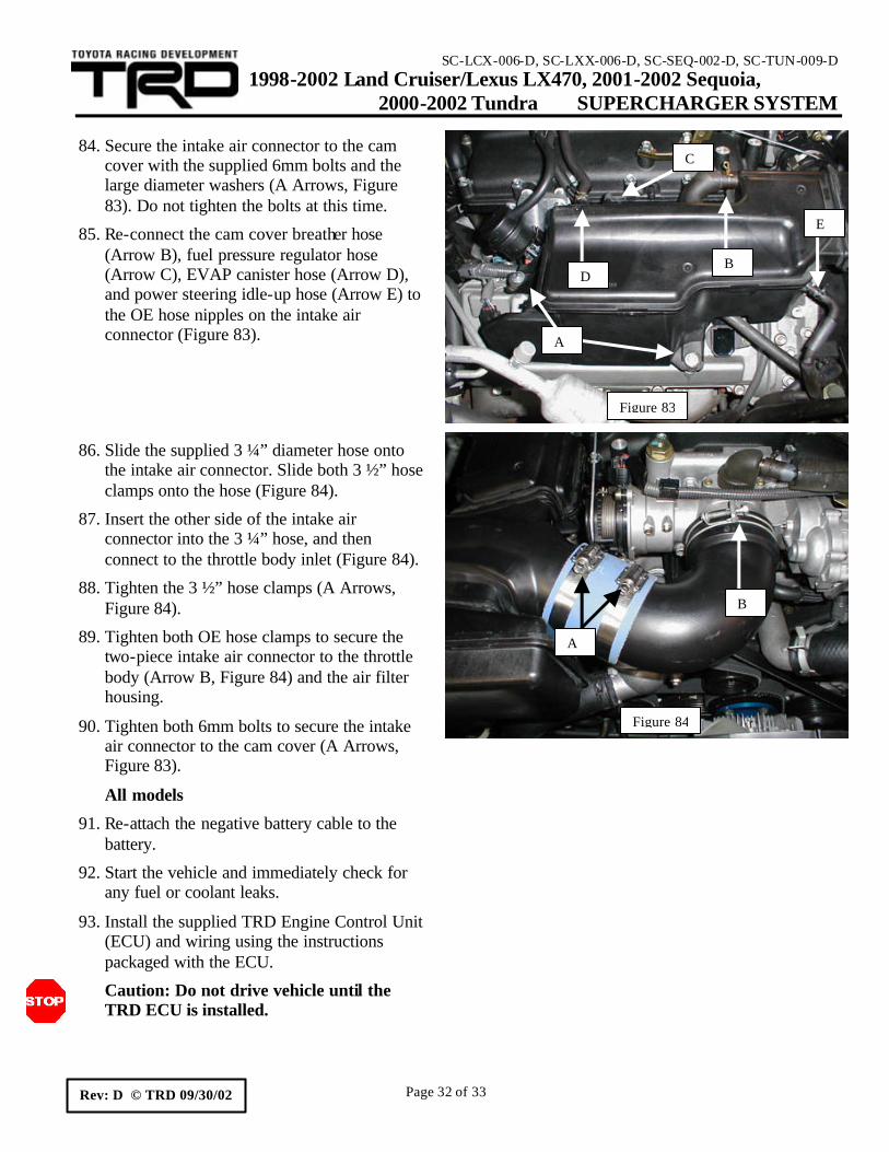
cover with the supplied 6mm bolts and the large diameter washers (A Arrows, Figure 83). Do not tighten the bolts at this time.
85. Re-connect the cam cover breather hose (Arrow B), fuel pressure regulator hose (Arrow C), EVAP canister hose (Arrow D), and power steering idle-up hose (Arrow E) to the OE hose nipples on the intake air connector (Figure 83).
86. Slide the supplied 3 ¼” diameter hose onto the intake air connector. Slide both 3 ½” hose clamps onto the hose (Figure 84).
87. Insert the other side of the intake air connector into the 3 ¼” hose, and then connect to the throttle body inlet (Figure 84).
88. Tighten the 3 ½” hose clamps (A Arrows, Figure 84).
89. Tighten both OE hose clamps to secure the two-piece intake air connector to the throttle body (Arrow B, Figure 84) and the air filter housing.
90. Tighten both 6mm bolts to secure the intake air connector to the cam cover (A Arrows, Figure 83).
All models
91. Re-attach the negative battery cable to the battery.
92. Start the vehicle and immediately check for any fuel or coolant leaks.
93. Install the supplied TRD Engine Control Unit (ECU) and wiring using the instructions packaged with the ECU.
Caution: Do not drive vehicle until the TRD ECU is installed.
Figure 83
A
B
C
D
E
Figure 84
A
B
SC-LCX-006-D, SC-LXX-006-D, SC-SEQ-002-D, SC-TUN-009-D 1998-2002 Land Cruiser/Lexus LX470, 2001-2002 Sequoia, 2000-2002 Tundra SUPERCHARGER SYSTEM
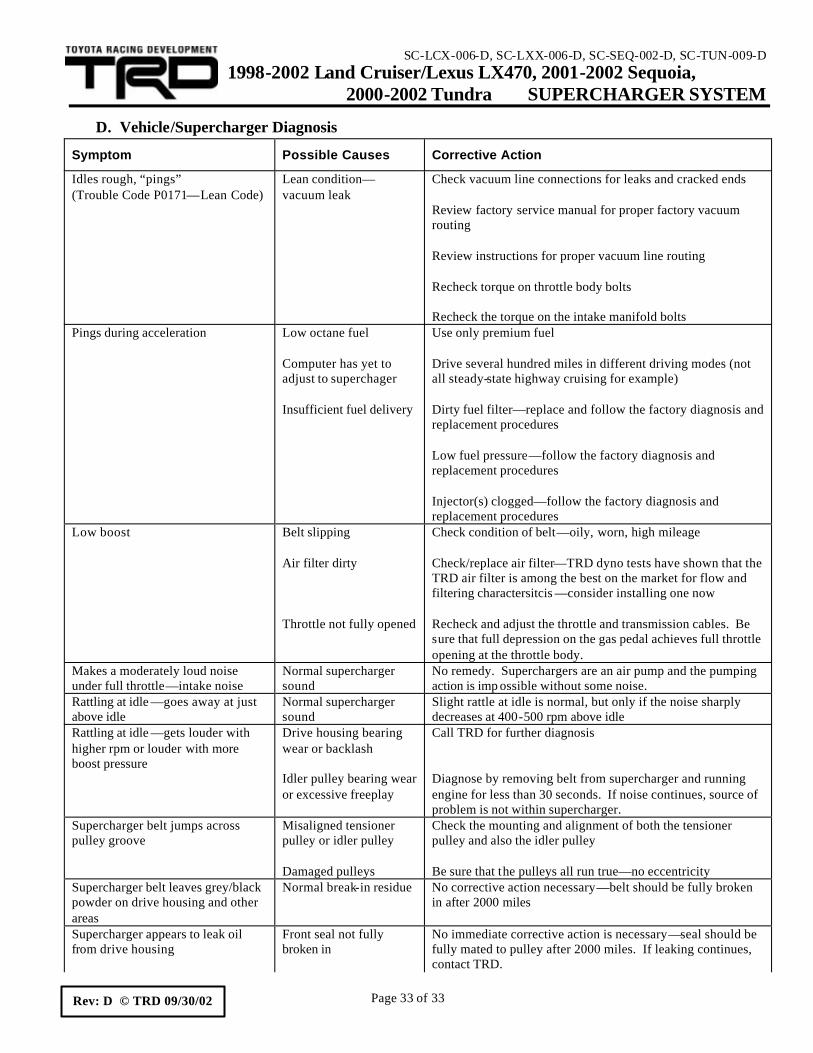
Check vacuum line connections for leaks and cracked ends
Review factory service manual for proper factory vacuum routing Review instructions for proper vacuum line routing
Recheck torque on throttle body bolts
Recheck the torque on the intake manifold bolts Pings during acceleration Low octane fuel
Computer has yet to adjust to superchager Insufficient fuel delivery
Use only premium fuel
Drive several hundred miles in different driving modes (not all steady-state highway cruising for example) Dirty fuel filter—replace and follow the factory diagnosis and replacement procedures Low fuel pressure—follow the factory diagnosis and replacement procedures Injector(s) clogged—follow the factory diagnosis and replacement procedures
Low boost Belt slipping
Air filter dirty
Throttle not fully opened
Check condition of belt—oily, worn, high mileage
Check/replace air filter—TRD dyno tests have shown that the TRD air filter is among the best on the market for flow and filtering charactersitcis —consider installing one now Recheck and adjust the throttle and transmission cables. Be sure that full depression on the gas pedal achieves full throttle opening at the throttle body.
Makes a moderately loud noise under full throttle—intake noise
Normal supercharger sound
No remedy. Superchargers are an air pump and the pumping action is imp ossible without some noise.
Rattling at idle —goes away at just above idle
Normal supercharger sound
Slight rattle at idle is normal, but only if the noise sharply decreases at 400-500 rpm above idle
Rattling at idle —gets louder with higher rpm or louder with more boost pressure
Drive housing bearing wear or backlash Idler pulley bearing wear or excessive freeplay
Call TRD for further diagnosis Diagnose by removing belt from supercharger and running engine for less than 30 seconds. If noise continues, source of problem is not within supercharger.
Supercharger belt jumps across pulley groove
Misaligned tensioner pulley or idler pulley Damaged pulleys
Check the mounting and alignment of both the tensioner pulley and also the idler pulley Be sure that the pulleys all run true—no eccentricity
Supercharger belt leaves grey/black powder on drive housing and other areas
Normal break-in residue No corrective action necessary—belt should be fully broken in after 2000 miles
Supercharger appears to leak oil from drive housing
Front seal not fully broken in
No immediate corrective action is necessary—seal should be fully mated to pulley after 2000 miles. If leaking continues, contact TRD.