- 1 - 1.System features - summary 1. Reads 125kHz EM type proximity or 13.56MHz Mifare cards. Wiegand port is capable of reading Wiegand 26 bit readers. (New versions with 26/34 bits) 2. Three selectable modes of operation: (a) card only (b) card with door code (c) card or door code for 377/5707/6730 series (d) free access mode.(optional) 3.The access map and system parameters are stored in non-volatile memory. The stored data can be retained for 10 years without external power supply. 4. The basic capacity is 9999cards for 4 digits mode with 10 definable facility. (2000 cards for 6 digits version models is for other selection) 5. The door released time can be freely programmed from 1 to 98 seconds. 6. Exit by pushing button or by out reader. 7. CMOS version CPU for low power consumption and silent operation. Watch-dog monitoring function prevents system disorders. 8. Featuring ABS case and making it easy to install and suitable for indoor use. And 6730/6700/5707/5700 are suitable for indoor or outdoor use. 377 /5707 series with plastic keypad, 370 series is keypad less. Also most commands are common to all Pegasus products.
Transcript
- 1 -
1.System features - summary 1. Reads 125kHz EM type proximity or 13.56MHz Mifare cards. Wiegand port is capable of reading Wiegand 26 bit readers. (New versions with 26/34 bits) 2. Three selectable modes of operation: (a) card only (b) card with door
code (c) card or door code for 377/5707/6730 series (d) free access mode.(optional)
3.The access map and system parameters are stored in non-volatile memory. The stored data can be retained for 10 years without external power supply.
4. The basic capacity is 9999cards for 4 digits mode with 10 definable facility.
(2000 cards for 6 digits version models is for other selection) 5. The door released time can be freely programmed from 1 to 98 seconds.
6. Exit by pushing button or by out reader. 7. CMOS version CPU for low power consumption and silent operation. Watch-dog monitoring function prevents system disorders. 8. Featuring ABS case and making it easy to install and suitable for indoor use. And 6730/6700/5707/5700 are suitable for indoor or outdoor use. 377 /5707 series with plastic keypad, 370 series is keypad less. Also most commands are common to all Pegasus products.
- - 2
9. Please set the waterproof rubber on the backside to avoid oxidation of devices. (5707/5878/5700 series)
- - 3
3. Instruction for Card Reading
1. Present the card parallel to the reader plate within 5~15cm. 2. If the left LED lights up green, the card reading is complete.
If the left LED lights up red, repeat above instructions, and check if the card has the right access privileges. Otherwise, use the code 5555 to check the 4 digits mode legal status.
Remark: The PUA-370/PUN-370 /5700/6700 are keypadless type, all of parameters and function codes shall be download through PC computer or PC-1037 multi-doors controller.
- - 4
A. Front Panel A . Front Panel for 377/378 A-1 Front Panel for 370 1. Power on lamp 2. Bicolor LED for access authorization/ deny or programming status indication etc... 3. Keypad 4. Reset key
1.Power on lamp 2.Bicolor LED for access authorization/deny or programming status indication ...etc.
- - 5
B . Front Panel for 5707/5878 B-1 . Front Panel for 5700
1. Power on lamp 2. Bicolor LED for access authorization/deny or programming status indication etc... 3. Keypad 4. Reset key
1. Power on lamp 2. Bicolor LED for access authorization/deny or programming status indication etc...
- - 6
C . Front Panel for 6730 68303 C-1 . Front Panel for 6700
1. Power on lamp 2. Bicolor LED for access authorization/deny or programming status indication etc... 3. Keypad 4. Reset key
1. Power on lamp 2. Bicolor LED for access authorization/deny or programming status indication etc...
- - 7
B. Bottom View A.377/378/370 series
1JA 9 pins blue for access connector 2JB 8 pins white for communication
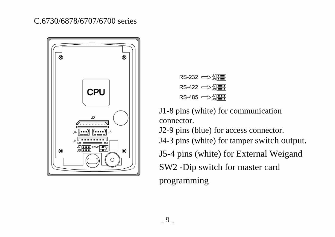
J1-8 pins (white) for communication connector. J2-9 pins (blue) for access connector. J4-3 pins (white) for tamper switch output. J5-4 pins (white) for External Weigand SW2 -Dip switch for master card programming
- - 10
4. Master Card & Project number loading
Please turn the rear and let DIP(1), DIP(2) switches up to "ON". Present the proximity card close to the reader. The red/green light will flash to show the master card setup is O.K. Turn the DIP(I) ,DIP(2)switches down to "OFF". The master card can now be used to program various functions once installation is completed. Also, the project number in master card is loaded into the memory for project number to be compared when 2801 code is enabled. For most versions, 10 master cards with different project number(differentiated by last digits) could be loaded.
5. System Factory Defaults
- - 11
Factory defaults are initiated by entering code "0800". The system parameters can be modified to user's requirements by entering the following function codes described in paragraph 7. Factory defaulted status :
( 1) Door monitoring : (1100) Do not monitor the door state
( 2) Safety zone state : (1200) The safety zone monitoring is disabled
( 3) Door release period : (2102) Released by 2 seconds
( 4) Alarm output period : (2206) Continued for 6 seconds
( 5) Door monitor period
: (2310) Maximum allowed time for door to remain open after granted access
( 6) Trial errors : (2403) Maximum access attempts allowed
( 7) Door Code digits : (4804) The door code is 4 digits if used
- - 12
6. Programming Procedures At first, please present master card to the reader or press "*" key and then the 6 digits master code for entering into programming state. Then you may program any of the function codes as described in section 6. A. Single section command: (4 digits command)
Commands examples: Group 1 commands : 1200/1, etc. Group 2 commands : 21tt, 22tt-2801, etc. Group 3 commands : 3100, 3200, etc.
Present master card or key in master code
Key in 4 digits command to return to ready state. (include implicit parameters)
Left LED stays in green and the buzzer
beeps
Left LED flashes green and red.
- - 13
B. Double sections command: (8 digits commands) Programming
Present master card or master code
Key in the 1~5 digits command codes (460n) and the succeeding 1-8 variable door codes or 4 digits card number, (5555/6666/7777) Return to
ready state
Left LED flashes green and red and the
buzzer beeps
Left LED flashes green, Waiting to key in
another 4 digits card no.
Left LED flashes green and red (under 460n)
Example Commands:
4601 dddddddd key in 8 digits door code for group 1, if 4808 is programmed or starting 4 digits
5555 cccc inquiry card status of 4 digits card number cccc
4609 kkkkkk key in 6 digits master pin
- - 14
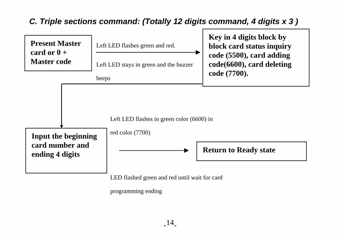
C. Triple sections command: (Totally 12 digits command, 4 digits x 3 )
Present Master card or 0 + Master code
Key in 4 digits block by block card status inquiry code (5500), card adding code(6600), card deleting code (7700).
Input the beginning card number and ending 4 digits Return to Ready state
Left LED flashes green and red.
Left LED stays in green and the buzzer
beeps
Left LED flashes in green color (6600) in
red color (7700)
LED flashed green and red until wait for card
programming ending
- - 15
7. Programming Instructions: 。GROUP 0 System configuration
0000 Clear all.(versions with 24LC256 memory) 0001 To delete the card number from 0001 to 2999 from 4 digits mode. 0002 To delete the card number 3000 to 6999 for 4 digits mode. 0003 To delete the card number from 7,000 to 9,999 for 4 digits mode. 0007 Clear all master card.(versions with 24LC256 memory) 0800 Initializes the system to the default status.
。GROUP 1 INPUT(input sensors enable or disable) 1101 Enables door sensor input. 1100 Disables door sensor input. 1201 Safety zone sensor input enabled. 1200 Safety zone sensor input disabled. ■ 1221 000W Weekday setting. Where ”W” is the weekdays from 1~7 for Monday to Sunday.(By 6730/6830 series LED Time Display) Ex: Monday : 0001 Tuesday : 0002 Sunday : 0007
- - 16
■ 1222 HH mm Time Setting where HHmm is the Hour and minute in 24 hours mode. Ex: 10:20am : 1020(By 6730/6830 series LED Time Display) 1300 If 1201 is installed and the door is opened by programmed code or card, it can re-close or not. *1301 If 1201 is installed and the door is opened legally, door must be manually
closed. (E) (F) pin of white connector are converted from alarm. or card, it can
re-close or not. ■*1331 Calendar year setting is followed by YYYY Ex: Year 2003 : 2003 (By 6730/6830 series LED Time Display) ■*1332 MM DD Calendar month and date setting. Ex: Sep. 3 : 0903 (By 6730/6830 series LED Time Display) " ■ " for version with Real time clock
- - 17
。GROUP 2 Output time period / counts configuring
21 tt Configures door strike/shunt output timer. tt is the digit timer in seconds (00-98).
22 tt Configures 2 digits alarm output timer (00-98). 2200 Alarm output will be inhibited. 2299 Alarm output will be latched until a valid access is
*2700 Disables duress function. *2701 Enables duress function.(Duress code is defined by "door code ± 1"and will trigger alarm for help as duress codes(For 4 digits ID version only)pressed) *2800 Does not compare project number. *2801 Compares project number, loaded by master card programming
- - 18
。GROUP 3 Operation mode
*3000 Access prohibited mode. 3200 Card only mode. 3300 Card and door code mode. 3400 Card or door code mode. 3601 Master card directly releases the door. *3800 Disable free access mode OFF (optional) *3801 Enable free access mode ON (optional)
- - 19
。GROUP 4 Adding / Deleting door codes
460n dddddddd The nth (n=1-5) group door code added. The actual digit varies from 1 – 8 digits defined by
command 480d. *4609 kkkkkk To modify the system supervisor code be kkkkkk.
470n To cancel the nth (n=1-5) group door code input 460n. 4700 Cancels all groups of codes. 480d Define door code digits ( d is the specified digit ranging
from 1 – 8 digits ).
- - 20
。GROUP 5 Card status inquiry For 4D version:
5500 bbbb eeee Checks the authorization status status of entire block of card numbers from bbbb to eeee.
5555 cccc Checks the specific card (card number cccc) status. Authorized card => right green LED flashes twice.
Unauthorized card => right red LED flashes twice.
For 6D version: 5500 bbbbbb eeeeee Checks the authorization status status of entire block of card numbers from bbbbbb to eeeeee. 5888 cccccc Present master card, key in 5888 and then key in the 6 digit ID number. For inquiry the card, the green light will indicate that the operation was successful. Repeat key in the next card number. To finish, press '#'.
- - 21
。GROUP 6 Adding authorized card For 4D version: <Block range adding mode>
6600 bbbb eeee Adds entire block of card numbers ranging from bbbb to eeee.
<Single card mode> 6666 cccc Adds single card (number cccc) as authorized card.
For 6D version: <Learning card mode> 6333 cccccc Present master card, key in 6333 and place proximity card close to the controller. Then this card number cccccc is added as authorized card. For next card repeat this procedure. To finish, press'#'.
- - 22
<Block range adding mode> 6600 bbbbbb eeeeee Adds entire block of card numbers ranging from bbbbbb to eeeeee. <Single card adding mode> 6888 cccccc Present master card, key in 6888 and then key in the 6 digit ID number. For adding the card, the green light will indicate that the operation was successful. Repeat key in the next card number. To finish, press '#'. 。Group 7 Deleting authorized card For 4D version: <Block range adding mode>
7700 bbbb eeee Delets entire block of card numbers ranging from bbbb to eeee.
<Single card mode> 7777 cccc Deletes single card (number cccc) as invalid card.
- - 23
For 6D version: <Learning card mode>
7333 cccccc Present master card, key in 7333 and place proximity card close to the controller. . To delete this proximity cards as illegal card. Continue this procedure for next card. To finish, press '#'. <Block range adding mode> 7700 bbbbbb eeeeee Deletes entire block of card numbers ranging from bbbbbb to eeeeee. <Single card adding mode> 7888 cccccc Present master card, key in 7888 and then key in the 6 digit ID number. The green light will indicate that the operation was successful. Repeat keyin the next card if needed. T o finish, press '#'.
- - 24
。GROUP 8. System configurations *8100 No printer report. *8101 Printer report for unauthorized access event. *8102 Printer report for authorized access event. *8103 Printer report for both authorized and unauthorized access events.
8400 Configure the reader as “ discard the event record “ mode. 8401 Configure the reader as “store the temporary event record“.
*8500 Query system parameter output to serial printer interface on PIN 9. 88nn Set device address as nn for polling. 890n Programs the waiting time for on-line PC. Larger polling systems
require the longer waiting times. For about 10 readers, the suggested code is 8903. If you set up the system as standalone or batch mode, or batch mode please use code 8900.
9nnn Recall the previous transactions in the buffer from nnn:001~999. Clear the memory buffer by 9000.
Note: All the function codes with “*” mark are reserved for printer options only. 8.Appendix(Regarding connection with PC-1037):
- - 25
1 377/5707/6730 are very compact keypadless/keypad proximity access controllers with integral proximity reader . It is equipped with RS485 for connecting with PC-1037 multi-doors access controller.
2 377/5707/6730 possesses the exit push button function, programmable door release and alarm relay driver, door held position monitoring and so forth. The parameters can be uploaded by PC-1037 remotely.
3 PC-1037 can control up to 20 pcs of 377/5707/6730 for on-line or off-line access controller system. Networking of PC-1037 thru PC or Internet is possible.
- - 26
PC-1037 4 PIN white connector
377/5707/6730 address
8 PIN white connector(01~09)
PIN colour Signal Name PIN colour Signal Name
1 Red A (RS-485) A Brown Rx+/Tx+ data +
2 Yellow B (RS-485) B Red Rx-/Tx- data -
3 Green × C Orange TxD+
4 Black × D Yellow TxD-
E Green Alarm Relay Output B
F Blue Alarm Relay Output B
G Purple Data Terminal Ready
H Gray Signal Ground
- - 27
PC-1037 4 PIN white connector
377/5707/6730…address
8 PIN white connector(10~19)
PIN colour Signal Name PIN colour Signal Name
1 Red ×
2 Yellow ×
3 Green A (RS-485) A Brown Rx+/Tx+ data +
4 Black B (RS-485) B Red Rx-/Tx- data -
C Orange TxD+
D Yellow TxD-
E Green Alarm Relay Output B
F Blue Alarm Relay Output B
G Purple Data Terminal Ready
H Gray Signal Ground
- - 28
9. Installation Guide 1. It’s surface mounted , please select a suitable position and appropriate height
to mount the reader , mark the position of the mounting holes. 2. Drill two 5 mm holes to fix the reader to the wall by using screws provided. 3. In normal state, the power on lamp “Yellow” LED will be in “ON” state, upon
legal / illegal card reading , another LED changes to Green / Red color. 4. Normally, please make sure to connect JA & JB connector wires of the reader. 5. Please supply 12 VDC with linear (not switching type) power supply and it’s
better not share with other devices (lock, readers...) 10. Wiring Diagram (Pin assignment for connecter)
- - 29
J4 (Blue) JA (Access port)—377/5707 series
J2(Access port)---6730 series
J2 (White) JB (Communication or Alarm port)-----377/5707 series
J1 (Communication or Alarm port)-----6730 series
JC(Blue) (Tamper switch output)---377/5707 series
JC (Blue)(Tamper switch output)---6730 series
J10 (White)JD (External Wiegand reader port)-----377/5707 series
J5 (White)JD (External Wiegand reader port)-----6730 series
- - 30
A. Pin assignment and description for socket JA (J4)
+12VDC ( DC power input )
GND
A Relay output (N.O.)
A Relay output (COM.).
A Relay output (N.C.)
+12 V for Exit push button
Door monitoring (shorted as door closed)
Security monitoring (shorted of normal)
Open collector printer output
(optional) to PG-1050B print adaptor
B.
(Red)
(Black)
(Brown)
(Orange)
(Yellow)
(Green)
(Blue)
(Purple)
(Gray)
1
2
3
4
5
6
7
8
9
- - 31
B. 377/5707/6730 Wiring diagram with external Pegasus’ proximity reader
377/5707/6730 (4 pins white) PUA-310 ( 4 pins)
□ .1 Red(DC 12V+) Red (DC 12V+) □ .2 Yellow(DATA 1) White (DATA 0) □ .3 Green(DATA 0) Green (DATA 1) □ .4 Black(GND-) Black (GND-)
377/5707/6730 (4 pins white) PP-5210 ( 9 pins)
□ .1 Red(DC 12V+) Red (DC 12V+) □ .2 Yellow(DATA 1) Brown (DATA 1) □ .3 Green(DATA 0) Orange (DATA 0) □ .4 Black(GND-) Black (GND-)
- - 32
C. Pin assignment and description for connector JB/J1.
RS-422 RS-485 □.A (Brown) ---------- Rx+/Tx+ data A (RxD+) A □.B (Red) ---------- Rx-/Tx- data B (RxD-) B □.C (Orange) ---------- TxD+ (TxD+) N.C. □.D(Yellow) ---------- TxD- (TxD-) N.C. *□.E (Green) ---------- Door driver for 2nd door COM. COM. *□.F (Blue) ----------- Door driver for 2nd door N.O. N.O. □.G (Purple) ----------- Data Terminal Ready DTR+ DTR+ □.H (Gray) ----------- Signal Ground (SG) (SG)
Communication pins (A.B.G) are used for one-line version PUA-377/PUN-377 (RS-422, RS-485 interface). Pins (E.F) serve as 2nd door driver as 1301 is enabled for two doors mode for some version.
- - 33
D. Summary description for 3 pin blue connector of tamper switch.
《Remark》The contacts between □.1 and □.3 is shorted as the case is well installed. The contacts between □.1 and □.3 is opened as the case is tampered. E. Summary description for 4 pins white connector of external
11.Wiring connection with external relay and power supply (such as magnetic lock or drop bolt type lock)
- - 36
Wiring connection with external relay and power supply (such as electric strike lock)
- - 37
12. On-Line System Configuration and Wiring Examples for communication
a. On-line system for multiple doors application by PCP832-XX
RS-232C
- - 38
b. On-line system for multiple doors application by RS-232 to RS-485 converters
- - 39
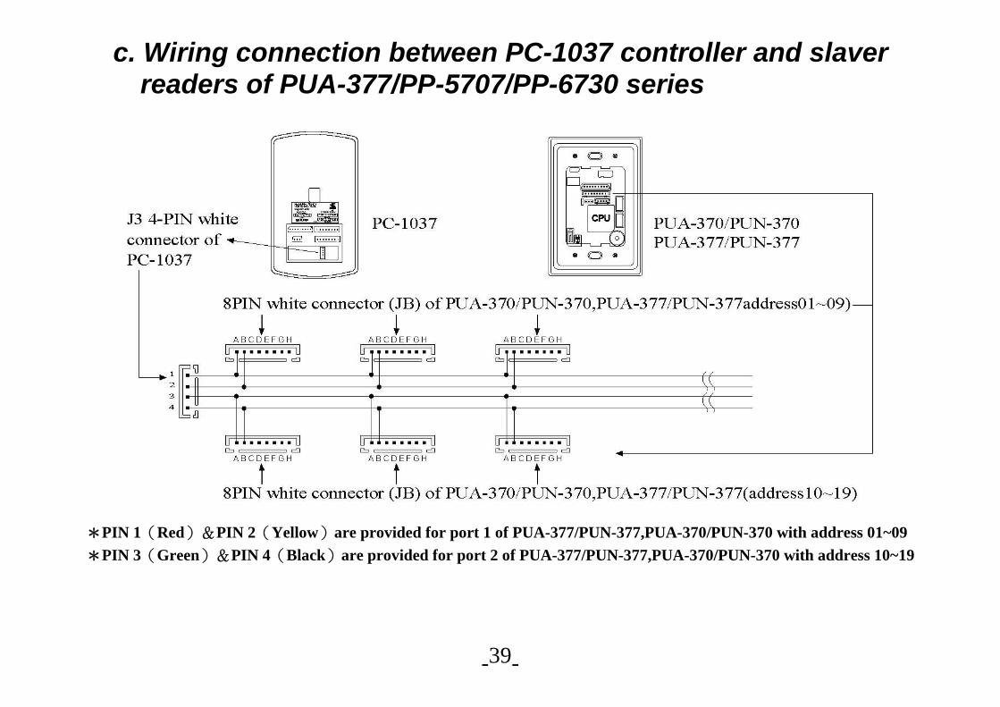
c. Wiring connection between PC-1037 controller and slaver readers of PUA-377/PP-5707/PP-6730 series
*PIN 1(Red)&PIN 2(Yellow)are provided for port 1 of PUA-377/PUN-377,PUA-370/PUN-370 with address 01~09 *PIN 3(Green)&PIN 4(Black)are provided for port 2 of PUA-377/PUN-377,PUA-370/PUN-370 with address 10~19
- - 40
The wire is Belden Communication Cable or UL2464 twist pair cable for RS-485/RS422, with copper braid shield or other characteristic equivalent cable. You should program the following code 0800, 8903, 88AA by PUA-377/PUN-377 itself or thru PC-1037 command 64AA (remote command) under F4 to program external reader PUA-377/PUN-377, PUA-370/PUN-370 , so that it can act as data sending /receiving unit to serve as slave readers to PC-1037. You may program 8903 for real time grant by PC-1037. If no personal data are up load by PC-1037. The PC-1037 could store legal and illegal event. Also, you may program 8900 and 8401 (save batch type event), so that each PUA-377,PUN-377/PUA-370,PUN-370 could judge the access and after a while, the PC-1037 will retrieve the data from each reader time recording. But for PUA-370, its address is fixed by jumping wire, you may program by key pad for PUA-377 for other functions or by PC-1037… The PUA-370/PUN-370, PUA-377/PUN-377 will lit green to signify the card reading is correct and then receive commands from PC-1037 to decide legal (flashing green LED) or illegal (flashing red LED) access status.
- - 41
13. Troubleshooting / FAQ: A. “POW” LED isn’t flashing and there is no response when card is used.
Check the power supply 12V DC and make sure it has been properly installed. B. “POW” LED stays in Green, but reader does not respond to card.
1. Check that proximity card is EM type, whether it matches the reader and whether it was acquired through our company. 2. Read the card shortly and check if the reader was installed without any interruption.
C. “DOR” LED(for 5707 series) stay in Red, and the reader beeps three times
after card is used. 1. Check whether the card is intended to be used with the reader. 2. Confirm that the card number was printed correctly.
D. “DOR” LED(for 5707 series) stays Green continuously after using card, but
the lock does not execute expected function. The reader may have been installed under “3300” mode. Key in door code.
- - 42
E. “DOR” LED(for 5707 series) stays Green and the lock executes function
continuously after card is used. The reader was installed in 2199 ON/OFF mode. Re-position card and wait for the “DOR” LED to turn off. Re-install 21nn (nn = 1-98) for door strike/shut output timer through Master card.
F. “DOR” LED(for 5707 series) flashes Green but lock does not open door
after using card. Check whether the diagram for reader & lock (page 26, 27) is connected Correctly; or the lock may be defective.
*Please insulate unused wiring well in order to avoid electrical short down.
- - 43
PROXIMITY ACCESS CONTROLLER (for 4D/6D) Ver.7.01
User’s Manual Ver. 7.01
0708ama W-04-377/5707/6730/E
377/5707/6730 System
- - 44
Table Of Contents 1.System features – summary…………………………………………………… 1
2.How to order…………………………………………………………………… 2
3. Instruction for Card Reading ……………………………………………….. 3 A. Front Panel……………………………………………………………….. B. Bottom view……………………………………………………………...
4 7
4. Master Card & Project number loading…………………………………… 10 5. System Factory Defaults……………………………………………………… 11 6. Programming Procedures:…………………………………………………... 12
7. Programming Instructions……………………………………………………. 8. Appendix(Regarding connection with PC-1037) 9.Installation Guide
15 25 28
10. Wiring Diagram (Pin assignment for connector)………………………….. 29
- - 45
A. Pin assignment and description for socket JA (J4)/J2…………………… B.377/5707/6730 Wiring diagram with external pegasus’s proximity reader……………………………………………………………………….
C.Pin assignment and description for connector JB/J1……………………
29
30 32
D.Summary description for 3 pins blue connector of tamper switch……. E.Summary description for 4 pins white connector of external Wiegand (For 377/5707/6730)………………………………………………………
E-1. Summary description for 4 pins white connector of external Wiegand(For 377/5707/6730)………………………………………………
33
33
34 11.Wiring connection with external relay and power supply (such as magnetic lock or drop bolt type lock) …………………………………...
Wiring connection with external relay and power supply (such as electric strike lock) ………………………………………………………
35
36
12. On-Line System Configuration and Wiring Examples for Communication………………………………………………………………
Thanks for purchasing 377 /5707 /6730 series Proximity access controller. Before operating the unit, please read this manual carefully and keep it for future reference.


![hir jugu jugu Bgq aupwieAw pYj nwmdyau muiK lwieAw ] jn ... - Rehiraas [Gurmukhi].pdf · hir jugu jugu Bgq aupwieAw pYj rKdw AwieAw rwm rwjy ] hrxwKsu dustu hir mwirAw pRhlwdu qrwieAw](https://static.documents.pub/doc/80x56/5a754e447f8b9a4b538c60f0/hir-jugu-jugu-bgq-aupwieaw-pyj-nwmdyau-muik-lwieaw-jn-rehiraas-gurmukhipdfaa.jpg)


