Linear Guideways EG Series 2-2-1 Features of the EG Series Linear Guideway The design of the EG series offers a low profile, high load capacity, and high rigidity. It also features an equal load rating in all four directions and self-aligning capability to absorb installation-error, allowing for higher accuracies. Additionally, the lower assembly height and the shorter length make the EG series more suitable for high-speed, automation machines and applications where space is limited. The retainer is designed to hold the balls in the block even when it is removed from the rail. 2-2-3 Model Number of EG Series EG series linear guideways are classified into non-interchangeable and interchangeable types. The sizes of these two types are the same as one another. The main difference is that the interchangeable type of blocks and rails can be freely exchanged and they can maintain P-class accuracy. Because of strict dimensional control, the interchangeable type linear guideways are a wise choice for customers when rails do not need to be matched for an axis. The model number of the EG series identifies the size, type, accuracy class, preload class, etc. Ball End seal (Double seals and scraper) Grease nipple End cap Block Rail Retainer Bottom seal 2-2-2 Construction of EG Series 2-2 EG Series - Low Profile Ball Type Linear Guideway Rolling circulation system: Block, rail, end cap and retainer Lubrication system: Grease nipple and piping Joint Dust protection system: End seal, bottom seal, cap and scraper Cap G99TE17-1306
Transcript
Linear GuidewaysEG Series
2-2-1 Features of the EG Series Linear Guideway
The design of the EG series offers a low profile, high load capacity, and high rigidity. It also features an equal load rating in all four directions and self-aligning capability to absorb installation-error, allowing for higher accuracies. Additionally, the lower assembly height and the shorter length make the EG series more suitable for high-speed, automation machines and applications where space is limited.The retainer is designed to hold the balls in the block even when it is removed from the rail.
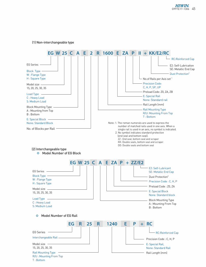
2-2-3 Model Number of EG SeriesEG series linear guideways are classified into non-interchangeable and interchangeable types. The sizes of these two types are the same as one another. The main difference is that the interchangeable type of blocks and rails can be freely exchanged and they can maintain P-class accuracy. Because of strict dimensional control, the interchangeable type linear guideways are a wise choice for customers when rails do not need to be matched for an axis. The model number of the EG series identifies the size, type, accuracy class, preload class, etc.
Ball
End seal(Double seals and scraper)
Grease nipple
End cap
BlockRail
Retainer
Bottom seal
2-2-2 Construction of EG Series
2-2 EG Series - Low Pro�le Ball Type Linear Guideway
Rolling circulation system: Block, rail, end cap and retainer
Lubrication system: Grease nipple and piping Joint
Dust protection system: End seal, bottom seal, cap and scraper
Cap
G99TE17-1306� �
Dust Protection2
E2: Self-LubricantSE: Metallic End Cap
Dust Protection2
E2: Self-LubricationSE: Metallic End Cap
RC:Reinforced Cap
(1) Non-interchangeable type
(2) Interchangeable typeModel Number of EG Block
Model Number of EG Rail
EG Series
Block Type
W : Flange Type
H : Square Type
Block Mounting Type
A : Mounting From Top
B : Bottom
E: Special Block
None: Standard block
Precision Code : C, H, P
Preload Code : Z0, ZA
EG Series
Rail Mounting Type
R/U : Mounting From Top
T : Bottom
Rail Length (mm)
E: Special Rail,
None: Standard Rail
RC:Reinforced Cap
Precision Code : C, H, PInterchangeable Rail
EG Series
Block Type
W : Flange Type
H : Square Type
Model size
15, 20, 25, 30, 35
No. of Blocks per Rail
Rail Length (mm)
E: Special Rail
None: Standard rail
Rail Mounting Type
R/U: Mounting From TopT : Bottom
Preload Code: Z0, ZA, ZB
Precision Code:
C, H, P, SP, UP
No.of Rails per Axis set 1
Load Type
C : Heavy Load
S: Medium Load
Block Mounting Type
A : Mounting from Top
B : Bottom
Model size
15, 20, 25, 30, 35
Load Type
C : Heavy Load S: Medium Load
Model size
15, 20, 25, 30, 35
Note: 1. The roman numerals are used to express the number of matched rails used in one axis. When a single rail is used in an axis, no symbol is indicated.
2. No symbol indicates standard protection (end seal and bottom seal).ZZ : End seal, bottom seal and scraperKK: Double seals, bottom seal and scraper.
DD: Double seals and bottom seal
E: Special Block
None: Standard Block
EG R 25 R 1240 E P + RC
EG W 25 C A E 2 R 1600 E ZA P II + KK/E2/RC
EG W 25 C A E ZA P + ZZ/E2
G99TE17-1306� �
Linear GuidewaysEG Series
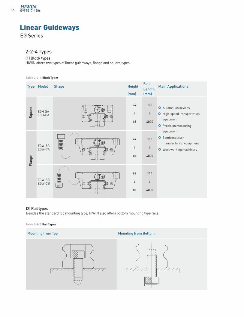
2-2-4 Types(1) Block typesHIWIN offers two types of linear guideways, flange and square types.
Type Model Shape HeightRail
LengthMain Applications
(mm) (mm)
EGH-SA EGH-CA
24
48
100
4000
Automation devices
High-speed transportation
equipment
Precision measuring
equipment
Semiconductor
manufacturing equipment
Woodworking machineryEGW-SA EGW-CA
24
48
100
4000
EGW-SB EGW-CB
24
48
100
4000
Sq
ua
re
Fla
ng
e
(2) Rail typesBesides the standard top mounting type, HIWIN also offers bottom mounting type rails.
Table 2-2-2 Rail Types
Mounting from Top Mounting from Bottom
Table 2-2-1 Block Types
G99TE17-1306� �
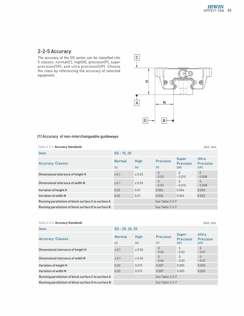
2-2-5 AccuracyThe accuracy of the EG series can be classified into 5 classes: normal(C), high(H), precision(P), super precision(SP), and ultra precision(UP). Choose the class by referencing the accuracy of selected equipment.
Table 2-2-3 Accuracy Standards Unit: mm
(1) Accuracy of non-interchangeable guideways
Item EG - 25, 30, 35
Accuracy ClassesNormal High Precision
Super
Precision
Ultra
Precision (C) (H) (P) (SP) (UP)
Dimensional tolerance of height H ± 0.1 ± 0.04 0- 0.04
0- 0.02
0- 0.01
Dimensional tolerance of width N ± 0.1 ± 0.04 0- 0.04
0- 0.02
0- 0.01
Variation of height H 0.02 0.015 0.007 0.005 0.003
Variation of width N 0.03 0.015 0.007 0.005 0.003
Running parallelism of block surface C to surface A See Table 2-2-7
Running parallelism of block surface D to surface B See Table 2-2-7
Item EG - 15, 20
Accuracy ClassesNormal High Precision
Super
Precision
Ultra
Precision (C) (H) (P) (SP) (UP)
Dimensional tolerance of height H ± 0.1 ± 0.03 0- 0.03
0- 0.015
0- 0.008
Dimensional tolerance of width N ± 0.1 ± 0.03 0- 0.03
0- 0.015
0- 0.008
Variation of height H 0.02 0.01 0.006 0.004 0.003
Variation of width N 0.02 0.01 0.006 0.004 0.003
Running parallelism of block surface C to surface A See Table 2-2-7
Running parallelism of block surface D to surface B See Table 2-2-7
Table 2-2-4 Accuracy Standards Unit: mm
NA
H
BD
C
G99TE17-1306� �
Linear GuidewaysEG Series
(2) Accuracy of interchangeable guideways
Table 2-2-5 Accuracy Standards Unit: mm
Item EG - 15, 20
Accuracy Classes Normal High Precision(C) (H) (P)
Dimensional tolerance of height H ± 0.1 ± 0.03 ± 0.015
Dimensional tolerance of width N ± 0.1 ± 0.03 ± 0.015
Variation of height H 0.02 0.01 0.006
Variation of width N 0.02 0.01 0.006
Running parallelism of block surface C to surface A See Table 2-2-7
Running parallelism of block surface D to surface B See Table 2-2-7
Item EG - 25, 30, 35
Accuracy Classes Normal High Precision(C) (H) (P)
Dimensional tolerance of height H ± 0.1 ± 0.04 ± 0.02
Dimensional tolerance of width N ± 0.1 ± 0.04 ± 0.02
Variation of height H 0.02 0.015 0.007
Variation of width N 0.03 0.015 0.007
Running parallelism of block surface C to surface A See Table 2-2-7
Running parallelism of block surface D to surface B See Table 2-2-7
Table 2-2-6 Accuracy Standards Unit: mm
(3) Accuracy of running parallelism
Rail Length (mm) Accuracy (µm)
C H P SP UP
~ 100 12 7 3 2 2
100 ~ 200 14 9 4 2 2
200 ~ 300 15 10 5 3 2
300 ~ 500 17 12 6 3 2
500 ~ 700 20 13 7 4 2
700 ~ 900 22 15 8 5 3
900 ~ 1,100 24 16 9 6 3
1,100 ~ 1,500 26 18 11 7 4
1,500 ~ 1,900 28 20 13 8 4
1,900 ~ 2,500 31 22 15 10 5
2,500 ~ 3,100 33 25 18 11 6
3,100 ~ 3,600 36 27 20 14 7
3,600 ~ 4,000 37 28 21 15 7
Table 2-2-7 Accuracy of Running Parallelism
G99TE17-1306� �
2-2-6 Preload(1) Definition
A preload can be applied to each guideway. Generally, a linear motion guideway has a negative clearance between the groove and balls in order to improve stiffness and maintain high precision. The figure shows that adding a preload can improve stiffness of the linear guideway. A preload not greater than ZA would be recommended for model sizes smaller than EG20. This will avoid an over-loaded condition that would affect guideway life.
2-2-7 Lubrication
Class Code Preload Condition
Very Light
PreloadZ0 0~ 0.02C Certain load direction,low impact, low precision required
Light
PreloadZA 0.03C~0.05C low load and high precision required
Medium
PreloadZB 0.06C~ 0.08C High rigidity required, with vibration and impact
Table 2-2-8 Preload Classes
(2) Preload classesHIWIN offers three standard preloads for various applications and conditions.
Class Interchangeable Guideway Non-Interchangeable Guideway
Preload classes Z0, ZA Z0, ZA, ZB
(1) Grease
Grease nipple
Ela
sti
c d
isp
lace
me
nt
Preload amount
ZBElastic displacement
with medium preload
Z0Elastic displacement
with very light preload
EG15M4x0.7P
NO.34310002
EG20EG25EG30EG35
NO.34310003(OPTION)
M6x0.75P
NO.34320001
M6x0.75P
EG20EG25EG30EG35
Note: The “C” in the preload column denotes basic dynamic load rating.
G99TE17-1306� �
Linear GuidewaysEG Series
Size Medium Load Heavy Load
(cm3) (cm3)
EG15 0.8 1.4
EG20 1.5 2.4
EG25 2.8 4.6
EG30 3.7 6.3
EG35 5.6 6.6
The standard location of the grease fitting is at both ends of the block, the nipple may be mounted in the side or top of the block. For lateral installation, we recommend that the nipple be mounted to the non-reference side, otherwise please contact us. When lubricating from above, in the recess for the O-ring, a smaller, preformed recess can be found. Preheat the 0.8 mm diameter metal tip. Carefully open the small recess with the metal tip and pierce through it. Insert a round sealing ring into the recess. (The round sealing ring is not supplied with the block) Do not open the small recess with a drill bit this may introduce the danger of contamination. It is possible to carry out the lubrication by using the oil-piping joint.
Mounting location
Size O-Ring
Lube hole at top: max. permissible depth for piercing
do(mm) W (mm) Tmax(mm)
EG15 2.5 ± 0.15 1.5 ± 0.15 6.9
EG20 4.5 ± 0.15 1.5 ± 0.15 8.4
EG25 4.5 ± 0.15 1.5 ± 0.15 10.4
EG30 4.5 ± 0.15 1.5 ± 0.15 10.4
EG35 4.5 ± 0.15 1.5 ± 0.15 10.8
The oil amount for a block filled with grease
Table 2-2-9 O-Ring size and max. permissible depth for piercing
Table 2-2-10 The oil amount for a block �lled with grease
Frequency of replenishment
Check the grease every 100 km, or every 3-6 months.
dia.0.8
Tmax
do
W
O Ring
G99TE17-1306� �
Size feed rate
(cm3/hr)
EG15 0.1
EG20 0.133
EG25 0.167
EG30 0.2
EG35 0.233
(2) OilThe recommended viscosity of oil is about 32~150cSt. If you need to use oil-type lubrication, please inform us.
Types of oil piping joint
Oil feeding rate
Table 2-2-11 oil feed rate
19
.5
M8x1.0P 18
10
M6x0.75P3
Ø8
NO.970002A1
LF-76
10
EG15NO.97000EA1
LF-64
EG20
EG25
EG30
EG35
PT 1/8
M6x0.75PØ8
11
NO.970004A1
12
23
.5
5
LF-86
11
EG20
EG25
EG30
EG35
M6x0.75P
M8x1.0P
10
19
.5
3
Ø8
10
NO.970001A1
SF-76
EG20
EG25
EG30
EG35
SF-86
EG20
EG25
EG30
EG35
NO.97001TA1
SF-64
EG15
8
16
.5
M6x0.75P
M4x0.7P
4
Ø6.5
10
7
Ø5.5
7.4
2.5
8
15
M6x0.75P
M4x0.7P
PT 1/8
12
23
.5
M6x0.75P Ø8
5
11
NO.970003A1
G99TE17-1306� �
Linear GuidewaysEG Series
Size Thickness (t1)(mm)
EG15 ES 2
EG20 ES 2
EG25 ES 2
EG30 ES 2
EG35 ES 2
(2) End seal and bottom seal Protects against contaminants entering the block. Reduces potential for groove damage resulting in a reduction of life ratings.
(3) Double sealsRemoving foreign matters from the rail to prevent contaminants from entering the block.
Table 2-2-12 Dimensions of end seal
2-2-8 Dust Protection Equipment
(1) Codes of equipment
If the following equipment is needed, please indicate the code followed by the model number.
�1�
2
Scraper
Bottom Seal
End seal
End seal
KK (Double seals + Bottom Seal + Scraper)
No symbol: Standard Protection
(End seal + Bottom seal)
Scraper
End seal
End seal
DD (Double seals + Bottom Seal)
ZZ(End seal + Bottom seal + Scraper)
G99TE17-1306�
Rail size Bolt size Diameter(D) Thickness(H)
(mm) (mm)
EGR15R M3 6.15 1.2
EGR20R M5 9.65 2.2
EGR25R M6 11.20 2.5
EGR30R M6 11.20 2.5
EGR35R M8 14.25 3.3
EGR15U M4 7.65 1.1
EGR30U M8 14.25 3.3
Size Thickness (t2)(mm)
EG15 SC 0.8
EG20 SC 0.8
EG25 SC 1
EG30 SC 1
EG35 SC 1.5
Table 2-2-13 Dimensions of Scraper
(4) ScraperClears larger contaminants, such as weld spatter and metal cuttings, from the rail. Metal scraper protects end seals from excessive damage.
(5) Bolt caps for rail mounting holesRail mounting hole caps prevent foreign matter from accumulating in the mounting holes. Caps are included with the rail package.
Table 2-2-14 Dimensions of Bolt Caps for Rail Mounting Holes
Ø
(6) Dimensions of block equipped with the dustproof parts
Because of the circular-arc contact design, the EG linear guideway can withstand surface-error installation and deliver smooth linear motion. When the mounting surface meets the accuracy requirements of the installation, the high accuracy and rigidity of the guideway will be obtained without any difficulty. For faster installation and smoother movement, HIWIN offers a preload with normal clearance because of its ability to absorb higher deviations in mounting surface inaccuracies.
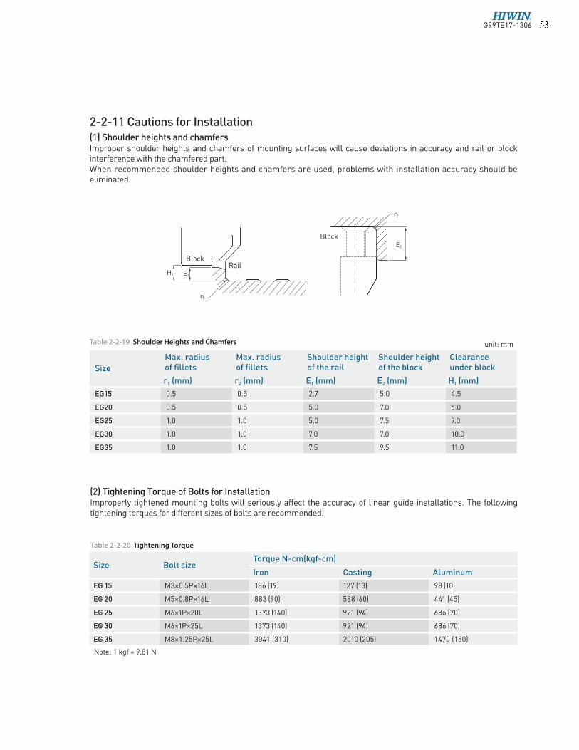
2-2-11 Cautions for Installation(1) Shoulder heights and chamfersImproper shoulder heights and chamfers of mounting surfaces will cause deviations in accuracy and rail or block interference with the chamfered part.When recommended shoulder heights and chamfers are used, problems with installation accuracy should be eliminated.
Table 2-2-19 Shoulder Heights and Chamfers
Table 2-2-20 Tightening Torque
(2) Tightening Torque of Bolts for InstallationImproperly tightened mounting bolts will seriously affect the accuracy of linear guide installations. The following tightening torques for different sizes of bolts are recommended.
Note: 1 kgf = 9.81 N
unit: mm
r2
E2
r1
E1H1
BlockRail
Block
G99TE17-1306� �
Linear GuidewaysEG Series
2-2-12 Standard and Maximum Lengths of Rail
HIWIN offers a number of standard rail lengths. Standard rail lengths feature end mounting hole placements set to predetermined values (E). For non-standard rail lengths, be sure to specify the E-value to be no greater than 1/2 the pitch (P) dimension. An E-value greater than this will result in unstable rail ends.
L : Total length of rail (mm)n : Number of mounting holesP : Distance between any two holes (mm)E : Distance from the center of the last hole to the edge (mm)
unit: mmTable 2-2-21 Rail Standard Length and Max. Length
L
E P E
n=(Number of rail mounting holes)
Note : 1. Tolerance of E value for standard rail is 0.5~-0.5 mm. Tolerance of E value for jointed rail is 0~-0.3 mm. 2. Maximum standard length means the max. rail length with standard E value on both sides.
3. If different E value is needed, please contact HIWIN.
G99TE17-1306� �
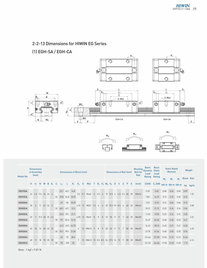
2-2-13 Dimensions for HIWIN EG Series
(1) EGH-SA / EGH-CA
Note : 1 kgf = 9.81 N
1
RW N
H
H
W
B 1 B
T
RH
E
Ød
P
ØD
H 2
h
G
EGH-CA
L KL
12
4-Mxl
C
H 3
1K
EGH-SA E
G L L 1
2-Mxl
1K
R M P
Y M M
K2
Model No.
Dimensions
of Assembly
(mm)
Dimensions of Block (mm) Dimensions of Rail (mm)
Mounting
Bolt for
Rail
Basic
Dynamic
Load
Rating
Basic
Static
Load
Rating
Static Rated
MomentWeight
MR
kN-m
MP
kN-m
MY
kN-m
Block
kg
Rail
kg/mH H1 N W B B1 C L1 L K1 K2 G Mxl T H2 H3 WR HR D h d P E (mm) C(kN) C0 (kN)