Market Information MAI 54 do uble row ! New! La teral gear teeth Four-row linear recirculating ball bearing and guideway assemblies Guideway with teeth on underside or toothed rack with lateral teeth For driven guideways, the four-row linear recirculating ball bearing and guideway assemblies KUVE..B ZHP have been available for some time. In these series, the guideways have right hand helical teeth with a mesh angle of 20°. The teeth are aligned downwards, hardened and ground. In comparison with units without teeth, these designs are more precise, allow significantly simpler adjacent constructions and give considerable reductions in fitting and logistical requirements. In order to increase further the potential applications of toothed guideways, the proven range has been expanded to include the series KUVE..B ZHST SVS. These units have a combination of a standard guideway TKVD with a toothed rack ZHST..SVS. Furthermore, the hardened and ground helical teeth are arranged laterally. This gives even more flexible fitting possibilities and increased free space in the design of the adjacent construction. Due to their modular design, the toothed series are suitable for all carriage types (except the wide W designs) and thus can be simply converted. The rolling element system of the guidance systems is lubricated by grease or oil. The teeth can be easily lubricated by means of felt gears and electronically controlled lubricators. The guidance systems can be used across a wide range of temperatures and are most suitable for applications in the handling equipment and automation technology sectors. 205 036
Transcript
Market Information MAI 54
double row!New!
Lateral gear t
eeth
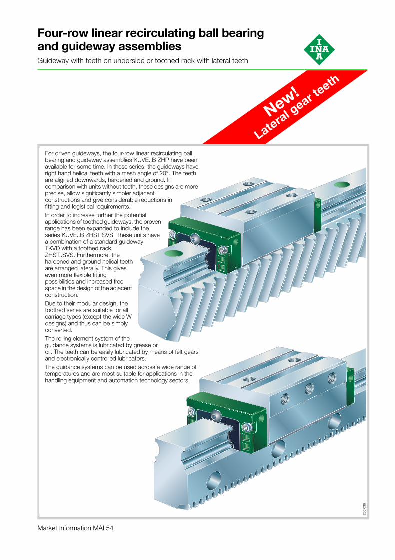
Four-row linear recirculating ball bearing and guideway assembliesGuideway with teeth on underside or toothed rack with lateral teeth
For driven guideways, the four-row linear recirculating ball bearing and guideway assemblies KUVE..B ZHP have been available for some time. In these series, the guideways have right hand helical teeth with a mesh angle of 20°. The teeth are aligned downwards, hardened and ground. In comparison with units without teeth, these designs are more precise, allow significantly simpler adjacent constructions and give considerable reductions in fitting and logistical requirements.In order to increase further the potential applications of toothed guideways, the proven range has been expanded to include the series KUVE..B ZHST SVS. These units have a combination of a standard guideway TKVD with a toothed rack ZHST..SVS. Furthermore, the hardened and ground helical teeth are arranged laterally. This gives even more flexible fitting possibilities and increased free space in the design of the adjacent construction.Due to their modular design, the toothed series are suitable for all carriage types (except the wide W designs) and thus can be simply converted.The rolling element system of the guidance systems is lubricated by grease or oil. The teeth can be easily lubricated by means of felt gears and electronically controlled lubricators.The guidance systems can be used across a wide range of temperatures and are most suitable for applications in the handling equipment and automation technology sectors.
205
036
2
Four-row linear recirculating ball bearing and guideway assembliesGuideway with teeth on underside
Page
Ordering example and ordering designation ....... 3
Design and safety guidelines............................... 10
Four-row linear recirculating ball bearing and guideway assemblies■ of these series are complete units comprising:
– a carriage KWVE..B or KWVE..B KT– a guideway TKVD..ZHP with helical gear teeth on the
underside■ expand on the advantages of units without teeth through:
– considerably reduced fitting work– increased accuracy– simplified design and machining of the adjacent
construction– reduced logistical work
■ are available in sizes 25 and 35■ are of a modular concept, i.e.:
– within one size, toothed guidance units can be combined with all carriage types (exception: wide W designs)
■ can support forces from all directions and moments about all axes
■ are preloaded■ have high load carrying capacity and rigidity■ can also be supplied as a preassembled unit for higher
accuracies■ have integral elastic wipers on the end faces of the
carriage and sealing strips for sealing the carriage■ can be lubricated with oil or grease
– the rolling contact is relubricated by means of a lubrication connector in the end piece of the carriage
– the teeth must be lubricated separately. For example, a felt gear and electronically controlled lubricator can be used
■ are suitable for temperatures from –10 °C to +100 °C■ are highly suitable for applications
– in the handling equipment and automation technology sectors.
Further information on the linear recirculating ball bearing and guideway assemblies: INA Catalogue “Monorail guidance systems” 605 and “MAI 91”, INA-CD-ROM “medias® professional”
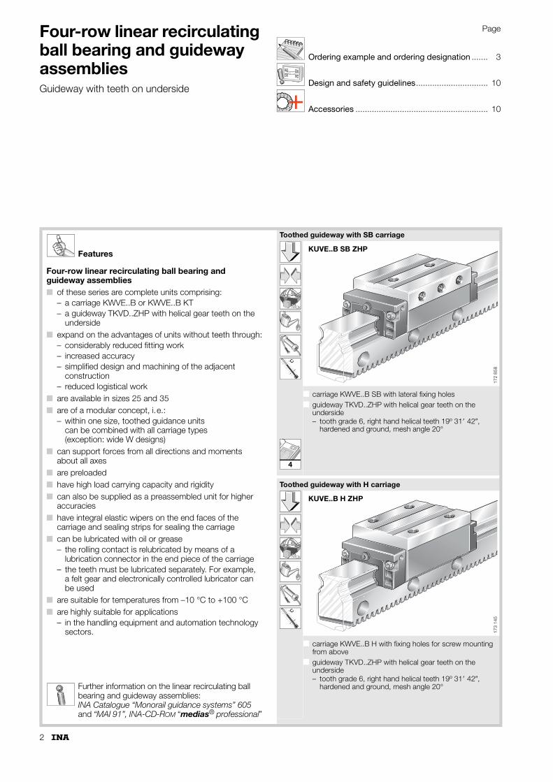
Toothed guideway with SB carriage
k0M
˚C
■ carriage KWVE..B SB with lateral fixing holes■ guideway TKVD..ZHP with helical gear teeth on the
underside– tooth grade 6, right hand helical teeth 19º 31� 42�,
hardened and ground, mesh angle 20°
Toothed guideway with H carriage
k0M
˚C
■ carriage KWVE..B H with fixing holes for screw mounting from above
■ guideway TKVD..ZHP with helical gear teeth on the underside– tooth grade 6, right hand helical teeth 19º 31� 42�,
hardened and ground, mesh angle 20°
KUVE..B SB ZHP
172
858
KUVE..B H ZHP17
3 14
5
4
3
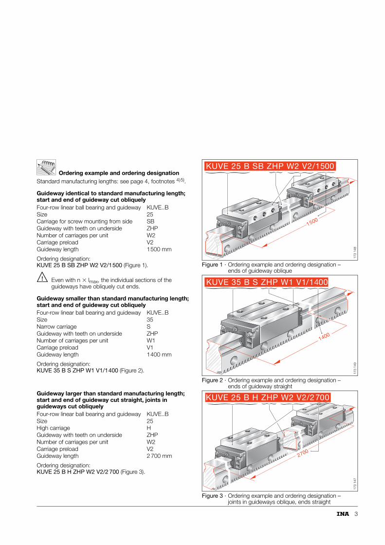
Ordering example and ordering designationStandard manufacturing lengths: see page 4, footnotes 4)5).
Guideway identical to standard manufacturing length; start and end of guideway cut obliquely
Even with n � lmax, the individual sections of the guideways have obliquely cut ends.
Guideway smaller than standard manufacturing length; start and end of guideway cut obliquely
Ordering designation:KUVE 35 B S ZHP W1 V1/1400 (Figure 2).
Guideway larger than standard manufacturing length; start and end of guideway cut straight, joints in guideways cut obliquely
Ordering designation: KUVE 25 B H ZHP W2 V2/2 700 (Figure 3).
Figure 1 · Ordering example and ordering designation – ends of guideway oblique
Figure 2 · Ordering example and ordering designation – ends of guideway straight
Figure 3 · Ordering example and ordering designation – joints in guideways oblique, ends straight
Four-row linear ball bearing and guideway KUVE..BSize 25Carriage for screw mounting from side SBGuideway with teeth on underside ZHPNumber of carriages per unit W2Carriage preload V2Guideway length 1500 mm
Four-row linear ball bearing and guideway KUVE..BSize 35Narrow carriage SGuideway with teeth on underside ZHPNumber of carriages per unit W1Carriage preload V1Guideway length 1400 mm
Four-row linear ball bearing and guideway KUVE..BSize 25High carriage HGuideway with teeth on underside ZHPNumber of carriages per unit W2Carriage preload V2Guideway length 2 700 mm
1500
KUVE 25 B SB ZHP W2 V2/1500
173
148
1400
KUVE 35 B S ZHP W1 V1/1400
173
149
2700
KUVE 25 B H ZHP W2 V2/2700
173
147
4
Four-row linear recirculating ball bearing and guideway assembliesGuideway with teeth on underside
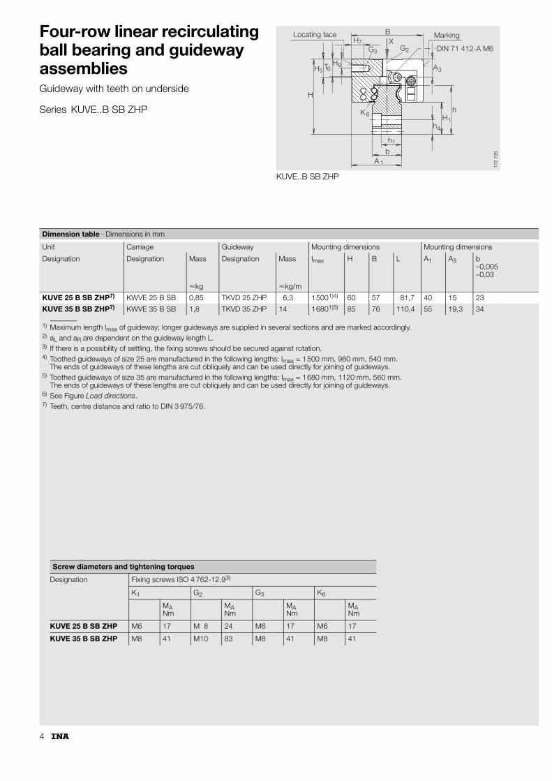
Series KUVE..B SB ZHP
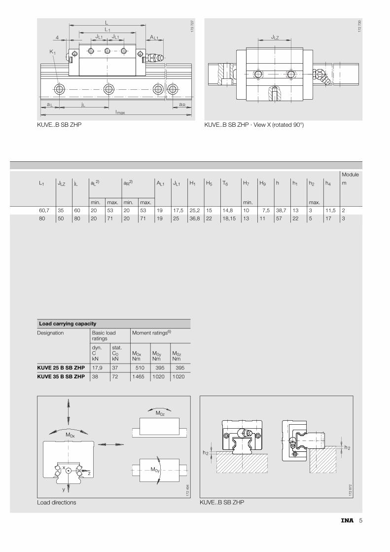
KUVE..B SB ZHP
7
3 2
3
14
1
6
1
965
H
H T H
K
h
bA
hH
h
A
GX
BH
G
Locating face Marking
DIN 71 412-A M6
172
726
1) Maximum length lmax of guideway; longer guideways are supplied in several sections and are marked accordingly.2) aL and aR are dependent on the guideway length L.3) If there is a possibility of settling, the fixing screws should be secured against rotation.4) Toothed guideways of size 25 are manufactured in the following lengths: lmax = 1500 mm, 960 mm, 540 mm.
The ends of guideways of these lengths are cut obliquely and can be used directly for joining of guideways.5) Toothed guideways of size 35 are manufactured in the following lengths: lmax = 1680 mm, 1120 mm, 560 mm.
The ends of guideways of these lengths are cut obliquely and can be used directly for joining of guideways.6) See Figure Load directions.7) Teeth, centre distance and ratio to DIN 3 975/76.
Dimension table · Dimensions in mm
Unit Carriage Guideway Mounting dimensions Mounting dimensions
Designation Designation Mass Designation Mass lmax H B L A1 A3 b–0,005–0,03
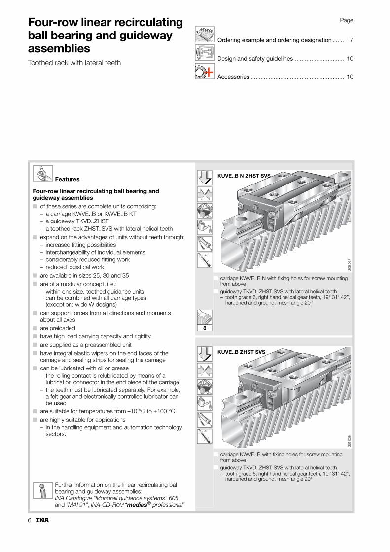
Four-row linear recirculating ball bearing and guideway assemblies■ of these series are complete units comprising:
– a carriage KWVE..B or KWVE..B KT– a guideway TKVD..ZHST– a toothed rack ZHST..SVS with lateral helical teeth
■ expand on the advantages of units without teeth through:– increased fitting possibilities– interchangeability of individual elements– considerably reduced fitting work– reduced logistical work
■ are available in sizes 25, 30 and 35■ are of a modular concept, i.e.:
– within one size, toothed guidance units can be combined with all carriage types (exception: wide W designs)
■ can support forces from all directions and moments about all axes
■ are preloaded■ have high load carrying capacity and rigidity■ are supplied as a preassembled unit■ have integral elastic wipers on the end faces of the
carriage and sealing strips for sealing the carriage■ can be lubricated with oil or grease
– the rolling contact is relubricated by means of a lubrication connector in the end piece of the carriage
– the teeth must be lubricated separately. For example, a felt gear and electronically controlled lubricator can be used
■ are suitable for temperatures from –10 °C to +100 °C■ are highly suitable for applications
– in the handling equipment and automation technology sectors.
Further information on the linear recirculating ball bearing and guideway assemblies: INA Catalogue “Monorail guidance systems” 605 and “MAI 91”, INA-CD-ROM “medias® professional”
k0M
˚C
■ carriage KWVE..B N with fixing holes for screw mounting from above
■ guideway TKVD..ZHST SVS with lateral helical teeth– tooth grade 6, right hand helical gear teeth, 19° 31� 42�,
hardened and ground, mesh angle 20°
k0M
˚C
■ carriage KWVE..B with fixing holes for screw mounting from above
■ guideway TKVD..ZHST SVS with lateral helical teeth– tooth grade 6, right hand helical gear teeth, 19° 31� 42�,
hardened and ground, mesh angle 20°
KUVE..B N ZHST SVS
205
037
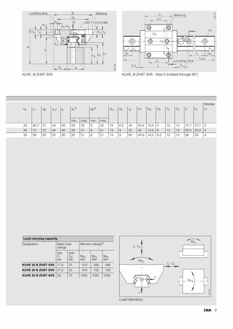
KUVE..B ZHST SVS20
5 03
8
8
7
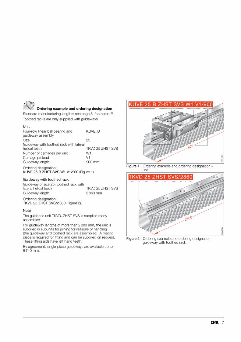
Ordering example and ordering designationStandard manufacturing lengths: see page 8, footnotes 1).Toothed racks are only supplied with guideways.
NoteThe guidance unit TKVD..ZHST SVS is supplied ready assembled.For guideway lengths of more than 2 880 mm, the unit is supplied in subunits for joining for reasons of handling (the guideway and toothed rack are assembled). A mating piece is required for fitting and can be supplied on request. These fitting aids have left hand teeth.By agreement, single-piece guideways are available up to 5 740 mm.
Figure 1 · Ordering example and ordering designation – unit
Figure 2 · Ordering example and ordering designation – guideway with toothed rack
Four-row linear ball bearing and guideway assembly
KUVE..B
Size 25Guideway with toothed rack with lateral helical teeth TKVD 25 ZHST SVSNumber of carriages per unit W1Carriage preload V1Guideway length 900 mm
Guideway of size 25, toothed rack with lateral helical teeth TKVD 25 ZHST SVSGuideway length 2 860 mm
KUVE 25 B ZHST SVS W1 V1/900
900
205
039
TKVD 25 ZHST SVS/2860
286020
5 05
8
8
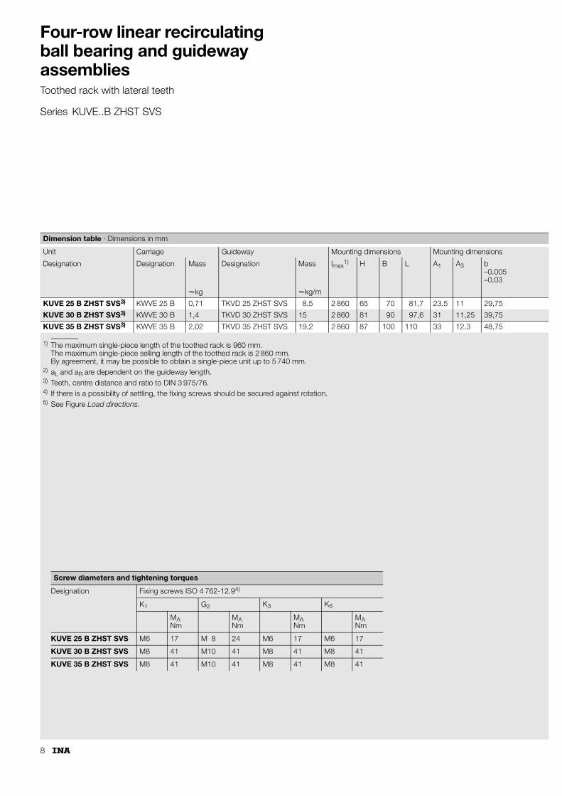
Four-row linear recirculating ball bearing and guideway assembliesToothed rack with lateral teeth
Series KUVE..B ZHST SVS
1) The maximum single-piece length of the toothed rack is 960 mm.The maximum single-piece selling length of the toothed rack is 2 860 mm.By agreement, it may be possible to obtain a single-piece unit up to 5 740 mm.
2) aL and aR are dependent on the guideway length.3) Teeth, centre distance and ratio to DIN 3 975/76.4) If there is a possibility of settling, the fixing screws should be secured against rotation.5) See Figure Load directions.
Dimension table · Dimensions in mm
Unit Carriage Guideway Mounting dimensions Mounting dimensions
Designation Designation Mass Designation Mass lmax1) H B L A1 A3 b
Four-row linear recirculating ball bearing and guideway assembliesGuideway with teeth on underside or toothed rack with lateral teeth
Design and safety guidelines
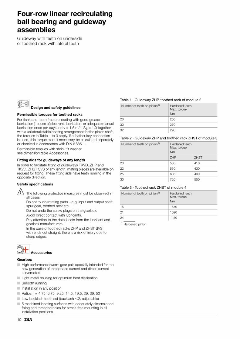
Permissible torques for toothed racksFor flank and tooth fracture loading with good grease lubrication (i.e. use of electronic lubricators or adequate manual lubrication once per day) and v = 1,5 m/s, SB = 1,0 together with a unilateral stable bearing arrangement for the pinion shaft, the torques in Table 1 to 3 apply. If a feather key connection is used, this torque must if necessary be calculated separately or checked in accordance with DIN 6 885-1.Permissible torques with shrink fit washer: see dimension table Accessories.
Fitting aids for guideways of any lengthIn order to facilitate fitting of guideways TKVD..ZHP and TKVD..ZHST SVS of any length, mating pieces are available on request for fitting. These fitting aids have teeth running in the opposite direction.
Safety specifications
The following protective measures must be observed in all cases:Do not touch rotating parts – e.g. input and output shaft, spur gear, toothed rack etc.Do not undo the screw plugs on the gearbox.Avoid direct contact with lubricants.Pay attention to the datasheets from the lubricant and gearbox manufacturers.In the case of toothed racks ZHP and ZHST SVS with ends cut straight, there is a risk of injury due to sharp edges.
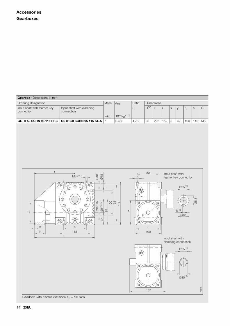
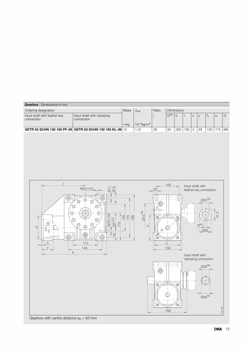
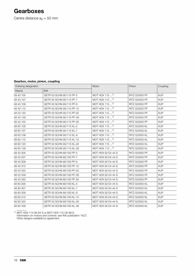
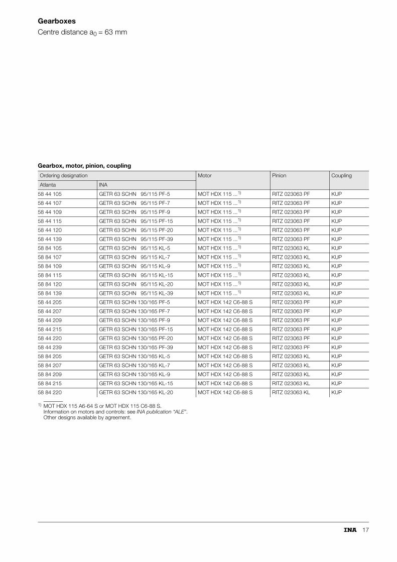
Accessories
Gearbox■ High performance worm gear pair, specially intended for the
new generation of threephase current and direct-current servomotors
■ Light metal housing for optimum heat dissipation■ Smooth running■ Installation in any position■ Ratios: i = 4,75; 6,75; 9,25; 14,5; 19,5; 29, 39, 50■ Low backlash tooth set (backlash �2, adjustable)■ 5 machined locating surfaces with adequately dimensioned
fixing and threaded holes for stress-free mounting in all installation positions.
1) Hardened pinion.
Table 1 · Guideway ZHP, toothed rack of module 2
Number of teeth on pinion1) Hardened teeth Max. torqueNm
28 250
30 270
32 290
Table 2 · Guideway ZHP and toothed rack ZHST of module 3
Number of teeth on pinion1) Hardened teeth Max. torqueNm
ZHP ZHST
20 505 410
22 530 430
25 605 490
30 720 550
Table 3 · Toothed rack ZHST of module 4
Number of teeth on pinion1) Hardened teeth Max. torqueNm
15 670
21 1020
24 1150
11
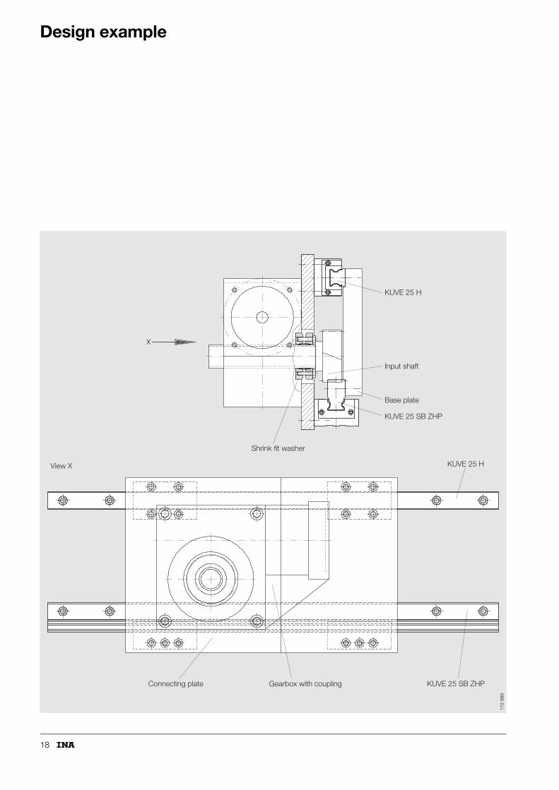
Mounting positionIf the additional forces are to be fully utilised, the gearbox should be flange mounted on the largest locating surfaces.The most favourable mounting position for lubrication is achieved with a lateral or bottom-mounted worm shaft.
With a top-mounted worm shaft, the drive power is reduced by approx. 10%.
Flank backlashThe flank backlash ist set to the smallest possible value at the manufacturing plant. If the backlash changes after a long period of operation, it can be corrected to the specified value by means of the eccentrically supported input shaft.
LubricationThe gearboxes are filled with synthetic lubricant. The filling should be checked monthly and several times in the first weeks of operation.
Under moderate load, the lubricant should be changed between once and four times per year (for single, double or triple shift operation).
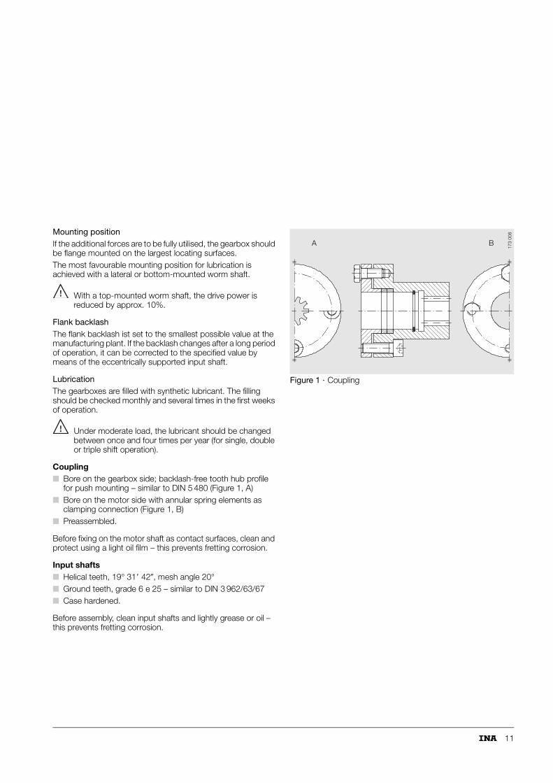
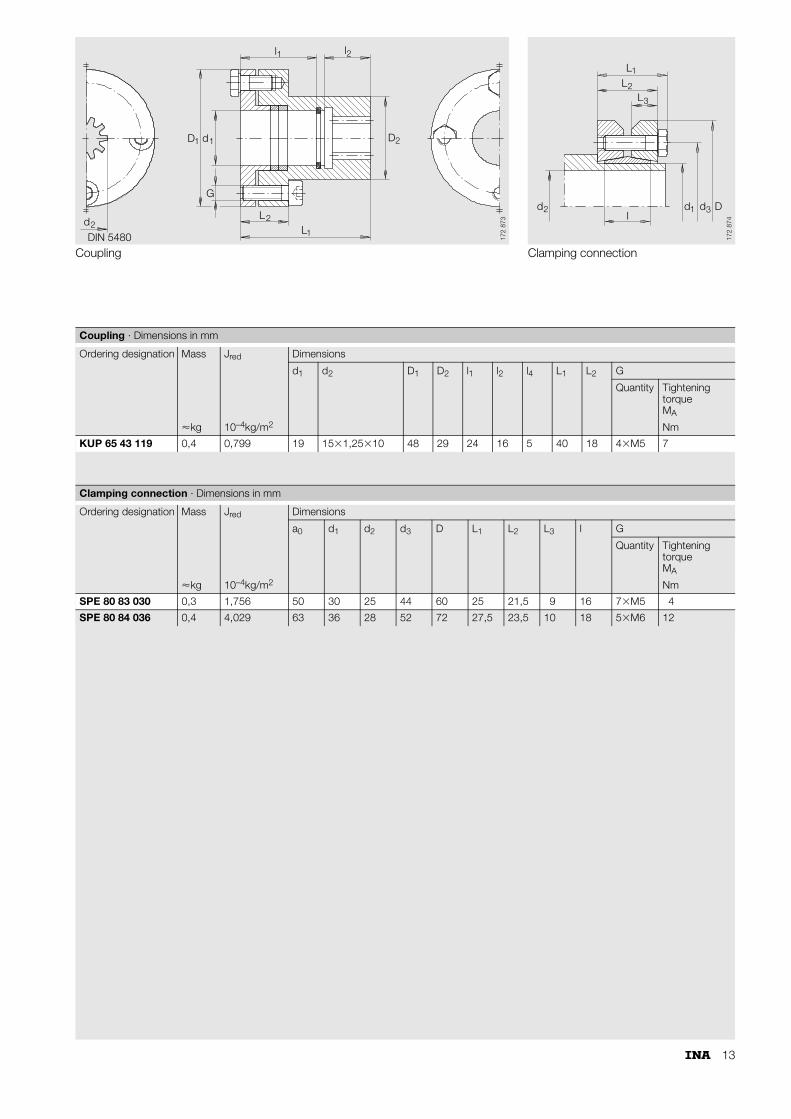
Coupling■ Bore on the gearbox side; backlash-free tooth hub profile
for push mounting – similar to DIN 5 480 (Figure 1, A)■ Bore on the motor side with annular spring elements as
clamping connection (Figure 1, B)■ Preassembled.
Before fixing on the motor shaft as contact surfaces, clean and protect using a light oil film – this prevents fretting corrosion.
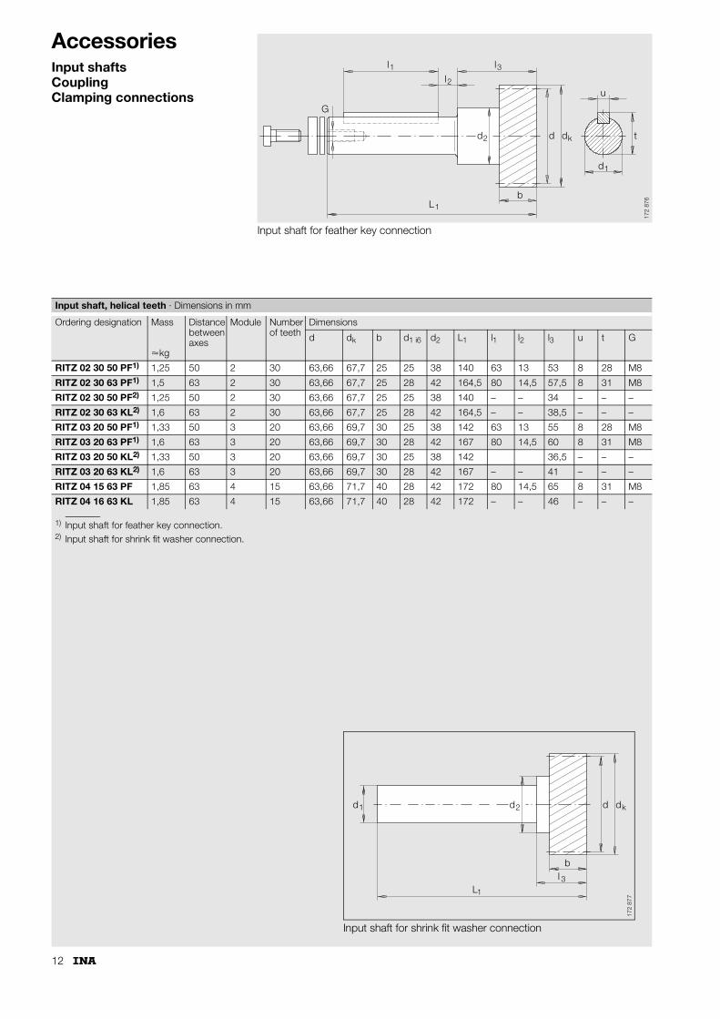
Input shafts■ Helical teeth, 19° 31� 42�, mesh angle 20°■ Ground teeth, grade 6 e 25 – similar to DIN 3 962/63/67■ Case hardened.
Before assembly, clean input shafts and lightly grease or oil – this prevents fretting corrosion.