Page 1
86 BARC HIGHLIGHTS Reactor Technology & Engineering
R & D f o r P H W R
The present nuclear power programme in India is based mainly on a series of 220 MWe pressurised heavy water reactors. These reactors use
pressure tube technology with natural uranium as fuel and heavy water as moderator and coolant. Currently, there are fifteen PHWRs in
operation including 540 MWe TAPS 4, the first of its kind in India. This chapter highlights the current R&D activities being carried out in the field
of physics design & safety assessment, fuel management studies, on-line flux mapping systems, fuelling machine testing, design of control and
shut off rod mechanisms, experimental studies and severe accident programmes.
2 . R & D F O R P H W R
I N T R O D U C T I O N
Page 2
87 Reactor Technology & Engineering BARC HIGHLIGHTS
R & D f o r P H W R
2.1 FUEL MANAGEMENT STUDIES TO OPTIMIZE
FUEL UTILIZATION IN INDIAN PHWRs
The optimised fuel management makes the best use of the fuel and
therefore reduces the unit energy cost. Hence different possible
alternatives have been studied to optimise the fuel utilisation in
Indian PHWRs. A few of them have been successfully implemented
in the power reactors. Fuel management code TRIVENI is being
used in all the power stations. The equilibrium core optimisation
studies have been performed by TAQUIL and the snapshot core
calculations were performed by TRIVENI.
The following burnup optimisation studies have been carried out
to improve the fuel utilisation in Indian PHWRs.
. Full power operation with corner adjusters fully withdrawn
from the core.. Reactor operation at reduced power with peaked flux
distribution.. Regular use of Depleted Uranium (DU) fuel at full
power operation.
. Use of depleted uranium in the initial fuel loading of the
new reactors and the reactors started after en-mass
coolant channel replacement activity.. Use of depleted uranium and deeply depleted uranium
(about 0.3% w/w) fuel in the initial fuel loading of TAPS-4
reactor (540 MWe).
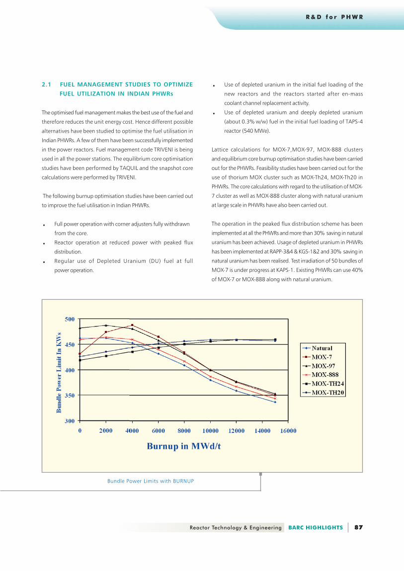
Lattice calculations for MOX-7,MOX-97, MOX-888 clusters
and equilibrium core burnup optimisation studies have been carried
out for the PHWRs. Feasibility studies have been carried out for the
use of thorium MOX cluster such as MOX-Th24, MOX-Th20 in
PHWRs. The core calculations with regard to the utilisation of MOX-
7 cluster as well as MOX-888 cluster along with natural uranium
at large scale in PHWRs have also been carried out.
The operation in the peaked flux distribution scheme has been
implemented at all the PHWRs and more than 30% saving in natural
uranium has been achieved. Usage of depleted uranium in PHWRs
has been implemented at RAPP-3&4 & KGS-1&2 and 30% saving in
natural uranium has been realised. Test irradiation of 50 bundles of
MOX-7 is under progress at KAPS-1. Existing PHWRs can use 40%
of MOX-7 or MOX-888 along with natural uranium.
Bundle Power Limits with BURNUP
Page 3
88 BARC HIGHLIGHTS Reactor Technology & Engineering
R & D f o r P H W R
2.2 REACTOR PHYSICS DESIGN AND SAFETY
ASSESSMENT OF PHWRS
. Criticality of 540 MWe PHWR
Safety of the physics design and commissioning procedures have
been evaluated for TAPS 3 & 4 units, of the 540 MWe PHWR design.
Significant changes in design of control and safety systems have
been incorporated for the first time in these reactors, due to their
larger size, compared to the standard 220 MWe PHWRs. Technical
specifications for operation has been evolved for first approach to
criticality and Phase – B commissioning of TAPS Unit # 4, the first
reactor of this kind in the country.
. Maximisation of discharge burn-up of
PHWR fuels
The design support and safety analysis for the changes in the fuelling
strategies for smooth transition from two burnup zone pattern
(Flat flux) to one zone pattern (Peak flux) for maximising the
Baltej Singh <[email protected] >
discharge burnup have been carried out. The evaluation of trial
irradiation of Pu MOX bundles in KAPS-1 reactor has been
completed. Presently, the design discharge burnup of PHWR bundle
is 15,000 MWd/t U and few bundles were irradiated beyond this
limit up to 20000 MWd/t U, to obtain physics data such as the fall
in the power production, changes in the
reactivity after refueling and also metallurgical details through post
irradiation examination (PIE). The extended irradiation of natural
uranium bundles in two specified channels have been analysed.
. Evolution of crit ical ity procedures for
re-tubed reactors and upgradation of
Computer code “Triveni”
Criticality procedures have been evolved for startup of reactors
after long shutdowns like en-mass coolant channel replacement
and these procedures have been approved by safety and
regulatory bodies (SARCOP and AERB) and have been
implemented in the approach to criticality of MAPS, Unit-2.
Page 4
89 Reactor Technology & Engineering BARC HIGHLIGHTS
R & D f o r P H W R
These are called the Flux Mapping ( FM ) detectors. They are one
pitch (28.6 cms) in length and made to measure the point
thermal flux at their locations. The electrical signal generated in
the FM detectors is due to the b decay of V. The relevant reaction
that takes place is as follows.
The response of FM detector lags behind the flux by about 5 minutes
due to β decay of V*52.
Flux Mapping ( FM ) Software
In OFMS software, the instantaneous neutron flux is expanded as
combination of pre-determined flux shapes whose combining
coefficients are determined from the on online flux
measurements by employing the Least Square method. The LS
procedure reduces the flux mapping software in just two matrix
multiplication. The first multiplication gives the instantaneous values
of the combining coefficients for modes corresponding to the FM
detector readings and the other multiplication gives the flux map
from the combining coefficients. Flux map thus generated is used
for calibrating the Cobalt SPNDs, used for controlling the reactor.
Validation of OFMS
Detailed programs for validation of OFMS software includes the
following;
Static configuration validation
The flux map generated is tested against large number of
theoretical simulation of possible reactor operating states. In this
validation, the detector readings are estimated from the flux shape
itself with random errors sampled from Gaussian
distribution superimposed on detector readings. Such detector
readings are fed to OFMS software to get the flux which is then
compared with the actual simulation. In this simulation no
dynamic feed-backs such as xenon, temperature etc. are
considered. Gross global feed-backs (as determined by the cross-
sections) are considered. This validation is used for determining the
size of basis set for expansion.
B. Krishna Mohan <[email protected] >
Modification of the fuel management code TRIVENI as and when
required and inclusion of special features such as the supply of
latest nuclear data files for better estimations of reactivity
coefficients is one of the important ongoing activities.
. Performance evaluation of Self Powered
Neutron Detectors
Data collection and analysis of the linear response with power
changes and dynamic response of SPNDs(Self Powered Neutron
Detectors) following transient change of power in KGS – 1 and
RAPS-3 was another valuable exercise taken up to validate and gain
confidence in the usage of SPNDs for regulation and protection in
540 MWe units. Usage of SPNDs for incore monitoring of neutron
flux during power operation would be a necessity in large size
reactors and hence has a lot of relevance for the AHWR as well as
700 MWe PHWR.
2.3 ON-LINE FLUX MAPPING SYSTEM (OFMS)
DEVELOPMENT FOR TAPS-3&4
Large power reactor systems, such as 540 MW(e) PHWRs, are known
to sustain power tilts following minor local reactivity perturbations.
If these tilts are not controlled, they can lead to unacceptable
power distributions. Therefore, it is essential to have in-core neutron
flux measurements and also to process them to get knowledge of
the operating state of the power reactor with the help of the On-
Line Flux Mapping System. This system is a virtually continuous
power regulating scheme to maintain the core power distribution
closer to the design intent.
Software for obtaining the power distribution from the in-core
neutron flux measurements has been developed.
. The physical OFMS system
Flux Mapping ( FM ) detectors
A total number of 102 Vanadium type in-core Self Powered
Neutron Detectors (SPNDs) are provided in 26 vertical assemblies.
Page 5
90 BARC HIGHLIGHTS Reactor Technology & Engineering
R & D f o r P H W R
A.K.Kulkarni <[email protected] >
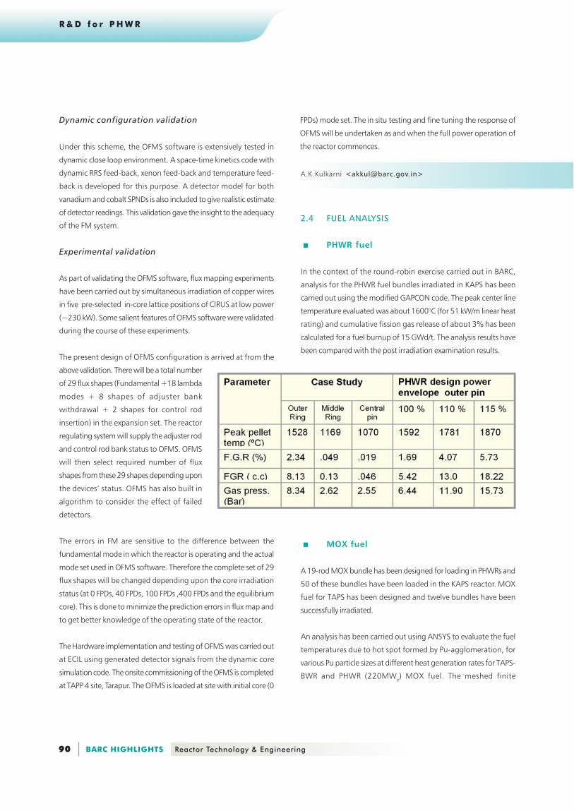
2.4 FUEL ANALYSIS
. PHWR fuel
In the context of the round-robin exercise carried out in BARC,
analysis for the PHWR fuel bundles irradiated in KAPS has been
carried out using the modified GAPCON code. The peak center line
temperature evaluated was about 1600°C (for 51 kW/m linear heat
rating) and cumulative fission gas release of about 3% has been
calculated for a fuel burnup of 15 GWd/t. The analysis results have
been compared with the post irradiation examination results.
. MOX fuel
A 19-rod MOX bundle has been designed for loading in PHWRs and
50 of these bundles have been loaded in the KAPS reactor. MOX
fuel for TAPS has been designed and twelve bundles have been
successfully irradiated.
An analysis has been carried out using ANSYS to evaluate the fuel
temperatures due to hot spot formed by Pu-agglomeration, for
various Pu particle sizes at different heat generation rates for TAPS-
BWR and PHWR (220MWe) MOX fuel. The meshed finite
Dynamic configuration validation
Under this scheme, the OFMS software is extensively tested in
dynamic close loop environment. A space-time kinetics code with
dynamic RRS feed-back, xenon feed-back and temperature feed-
back is developed for this purpose. A detector model for both
vanadium and cobalt SPNDs is also included to give realistic estimate
of detector readings. This validation gave the insight to the adequacy
of the FM system.
Experimental validation
As part of validating the OFMS software, flux mapping experiments
have been carried out by simultaneous irradiation of copper wires
in five pre-selected in-core lattice positions of CIRUS at low power
(~230 kW). Some salient features of OFMS software were validated
during the course of these experiments.
The present design of OFMS configuration is arrived at from the
above validation. There will be a total number
of 29 flux shapes (Fundamental +18 lambda
modes + 8 shapes of adjuster bank
withdrawal + 2 shapes for control rod
insertion) in the expansion set. The reactor
regulating system will supply the adjuster rod
and control rod bank status to OFMS. OFMS
will then select required number of flux
shapes from these 29 shapes depending upon
the devices’ status. OFMS has also built in
algorithm to consider the effect of failed
detectors.
The errors in FM are sensitive to the difference between the
fundamental mode in which the reactor is operating and the actual
mode set used in OFMS software. Therefore the complete set of 29
flux shapes will be changed depending upon the core irradiation
status (at 0 FPDs, 40 FPDs, 100 FPDs ,400 FPDs and the equilibrium
core). This is done to minimize the prediction errors in flux map and
to get better knowledge of the operating state of the reactor.
The Hardware implementation and testing of OFMS was carried out
at ECIL using generated detector signals from the dynamic core
simulation code. The onsite commissioning of the OFMS is completed
at TAPP 4 site, Tarapur. The OFMS is loaded at site with initial core (0
FPDs) mode set. The in situ testing and fine tuning the response of
OFMS will be undertaken as and when the full power operation of
the reactor commences.
Page 6
91 Reactor Technology & Engineering BARC HIGHLIGHTS
R & D f o r P H W R
Meshed finite element model for pellet with the particle
TAPS-BWR fuel: Variation of particlemaximum temperature with heat generation ratios
for different particle sizes
V.Shivakumar <[email protected] ?
element model for pellet with the particle is shown in Figure.
The fabrication specification for the maximum Pu-rich particle size
is in the range of 200-400 microns. The analysis shows that the
agglomerates can cause spikes in fuel temperatures of about 300-
500°C depending upon the size and concentration of Pu in the
agglomerate. Variation of particle maximum temperature for various
heat generation ratios and for different particle sizes for TAPS-BWR
fuel are illustrated. The presence of the Pu-rich particle on the
surface of pellet will result in clad temperature rise of only about
100-2000C.
2.5 TEST ING OF FUELL ING MACHINE OF
540 MWe PHWR
The Fuelling Machine of 540 MWe PHWR Reactor is an important
intricate equipment. For satisfactory performance of the assembled
Fuelling Machine, Performance & acceptance testing of Fuelling
Machine is carried out under the simulated reactor conditions.
. Fuelling Machine Test Facility (FMTF)
Fuelling Machine Test Facility has been set up and fuelling machine
head is installed on the test carriage and the oil hydraulic water
hydraulic systems have been commissioned. The fuelling machine
head has been calibrated & commissioned. Necessary rectification
and fine-tuning of fuelling machine head have been incorporated
by suitable modification /changes of components.
The following tests were done in reactor-simulated condition:. Performance testing:- 6 times bundles loading & 6 times
bundles receiving.. Acceptance testing : 10 times bundles loading & 10 times bundles
receiving.. Cycling of Ram extension:- 10 times loading and 10 times
receiving.
The fuelling machine head has been qualified with successful
completion of above tests. Full testing has been completed in very
short period of 5 months.
S. Raghunathan <[email protected] >
An analysis has been carried out for MOX fuel pins irradiated at
PWL CIRUS, as part of round robin exercise, using modified GAPCON
code. The peak centreline temperature evaluated was in the range
of 1300°C (for 42kW/m linear heat rating) and cumulative fission
gas release of about 2.0% for fuel burnup of 16 GWd/t.
Page 7
92 BARC HIGHLIGHTS Reactor Technology & Engineering
R & D f o r P H W R
2.7 DESIGN AND DEVELOPMENT OF ADJUSTOR
ROD, CONTROL ROD AND SHUT-OFF ROD
DRIVE MECHANISM FOR TAPS 3 & 4
This development work has been taken up under an MoU signed
between BARC and NPCIL. The control mechanisms for TAPS units
3&4 are designed with a number of advanced features like modular
construction giving ease of maintenance, 90% free fall for shut-off
rod/control rods giving high reliability and consistent rod drop
performance, on-line test facility for shut-off rods to ensure rod
availability on demand while reactor is under operation and partial
release & re-arresting of control rods for reactor step back function.
Design, prototyping, testing & qualification on full-scale test set-up
have been completed. Manufacture, assembly and testing of drive
units for reactor use have been completed. They have been installed
and commissioned at TAPS-4.
Full-scale test set-up at BARC
2.6 TESTING OF RAM ASSEMBLY OF 540 MWe
PHWR
For satisfactory performance of the assembled fuelling machine,
elaborate testing of various sub-assemblies of fuelling machine is
carried out separately. Later, the assembled fuelling machine has
been again completely tested before delivery to the site.
RAM assembly is one of the important subassembly of the fuelling
machine and it is the first of its kind, to be used in 540 MWe
PHWRs. It comprises of three telescopic rams namely B Ram, C Ram
& Latch Ram. All these rams are operated through oil hydraulic
motors. B Ram & C Ram are provided with water hydraulic back up.
These rams are used for refuelling operations & various plug
operations.
Ram assembly and the Oil & water Hydraulic system has been
installed and commissioned. The calibration & commissioning of
the Ram assembly in the Ram assembly test facility has been
completed.
S. Raghunathan <[email protected] >
Ram assembly test facility(RATF)
Necessary rectification and fine tuning of Ram assembly have been
incorporated by suitable modification /changes of components.
The B Ram Cycling equivalent to 300 channel refueling operation &
Plug operations equivalent to 100 channel refueling operation have
been successfully carried out to qualify the Ram assembly.
Page 8
93 Reactor Technology & Engineering BARC HIGHLIGHTS
R & D f o r P H W R
D. N. Badodkar <[email protected] >
Typical rod drop characteristics for shut-off rodfor TAPS, units 3 & 4
Reactivity control mechanisms on deck plateof TAPS unit 4
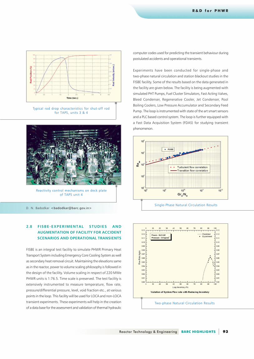
2.8 F ISBE-EXPERIMENTAL STUDIES AND
AUGMENTATION OF FACILITY FOR ACCIDENT
SCENARIOS AND OPERATIONAL TRANSIENTS
FISBE is an integral test facility to simulate PHWR Primary Heat
Transport System including Emergency Core Cooling System as well
as secondary heat removal circuit. Maintaining the elevations same
as in the reactor, power to volume scaling philosophy is followed in
the design of the facility. Volume scaling in respect of 220 MWe
PHWR units is 1:76.5. Time scale is preserved. The test facility is
extensively instrumented to measure temperature, flow rate,
pressure/differential pressure, level, void fraction etc., at various
points in the loop. This facility will be used for LOCA and non-LOCA
transient experiments. These experiments will help in the creation
of a data base for the assessment and validation of thermal hydraulic
Single-Phase Natural Circulation Results
Two-phase Natural Circulation Results
computer codes used for predicting the transient behaviour during
postulated accidents and operational transients.
Experiments have been conducted for single-phase and
two-phase natural circulation and station blackout studies in the
FISBE facility. Some of the results based on the data generated in
the facility are given below. The facility is being augmented with
simulated PHT Pumps, Fuel Cluster Simulators, Fast Acting Valves,
Bleed Condenser, Regenerative Cooler, Jet Condenser, Pool
Boiling Coolers, Low Pressure Accumulator and Secondary Feed
Pump. The loop is instrumented with state of the art smart sensors
and a PLC based control system. The loop is further equipped with
a Fast Data Acquisition System (FDAS) for studying transient
phenomenon.
Page 9
94 BARC HIGHLIGHTS Reactor Technology & Engineering
R & D f o r P H W R
Primary Circulating Pump
Low Pressure Accumulator
Quick Opening Valve
PC Based Control
Fast Data Acquisition System
A.K. Pal <[email protected] >N.V.Satish Kumar <[email protected] >
Jet Condenser
Page 10
95 Reactor Technology & Engineering BARC HIGHLIGHTS
R & D f o r P H W R
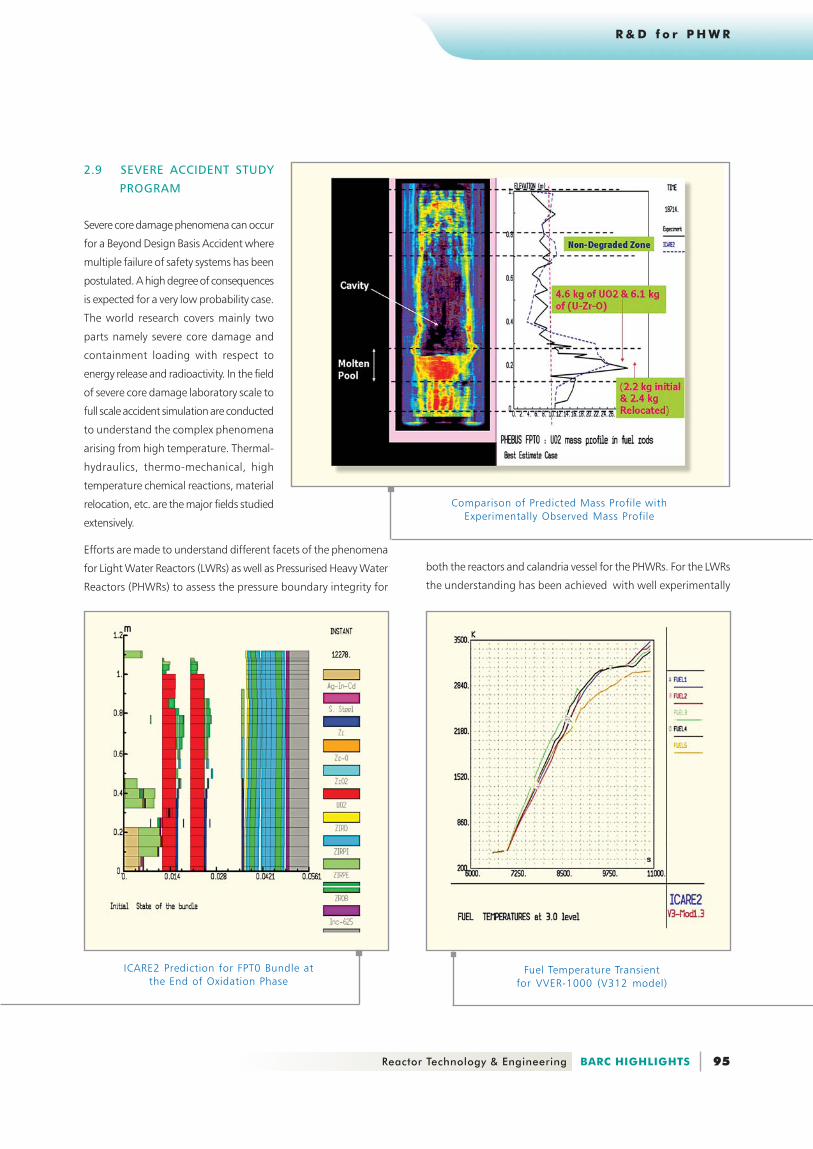
Comparison of Predicted Mass Profile withExperimentally Observed Mass Profile
ICARE2 Prediction for FPT0 Bundle atthe End of Oxidation Phase
Fuel Temperature Transientfor VVER-1000 (V312 model)
2.9 SEVERE ACCIDENT STUDY
PROGRAM
Severe core damage phenomena can occur
for a Beyond Design Basis Accident where
multiple failure of safety systems has been
postulated. A high degree of consequences
is expected for a very low probability case.
The world research covers mainly two
parts namely severe core damage and
containment loading with respect to
energy release and radioactivity. In the field
of severe core damage laboratory scale to
full scale accident simulation are conducted
to understand the complex phenomena
arising from high temperature. Thermal-
hydraulics, thermo-mechanical, high
temperature chemical reactions, material
relocation, etc. are the major fields studied
extensively.
Efforts are made to understand different facets of the phenomena
for Light Water Reactors (LWRs) as well as Pressurised Heavy Water
Reactors (PHWRs) to assess the pressure boundary integrity for
both the reactors and calandria vessel for the PHWRs. For the LWRs
the understanding has been achieved with well experimentally
Page 11
96 BARC HIGHLIGHTS Reactor Technology & Engineering
R & D f o r P H W R
Temperature for CT Boiling
To support the code development, experiments for studying pipe
blowdown and vapor pull through in the reactor headers are planned
for the initial phase of the accident. The next phase includes the
experiments of channel heat up leading to thermo-mechanical
phenomena in the pressure tube and boiling crisis of calandria tube
with sagging and ballooning. Release of molten material from reactor
channels and its distribution due to its neighbouring channels will
be studied through the fuel coolant interaction experiments
H. G. Lele <[email protected] >
validated severe accident analysis computer codes namely ICARE/
CATHARE, ASTEC and RELAP/SCADAP and participation in the
experimental validation program of PHEBUS-FPT0 experiment with
code ICARE2. Some of the computational prediction are shown
below for FPT0 experiment and fuel temperatutre transient for
small break Loss of Coolant Accident with station Black out of
VVER-1000.
For PHWR theoretical model developments namely Channel
Analysis in Severe Accident (CHASA), Fuel Coolant Interaction (FCI)
and Molten Pool (MPOOL) code are being developed. At present
CHASA features in-channel thermal-hydraulic models, more
emphasis on radiation among fuel pins and from fuel pins to pressure
tube(PT), thermo-mechanical deformation model of pressure tube,
calandriatube(CT) outer surface boiling crisis and high temperature
chemical reaction model. Melting of the fuel pins, relocation and
oxidation of the molten material, are the areas on which work is to
be carried forward. Some predictions during the development period
are cited below,
Two dimensional Computational Fluid Dynamics (CFD) Code
development for Fuel Coolant Interaction (FCI) and behaviour of
Molten Pool (MPOOL) arising from corium as a result of Beyond
Design Basis Accident (BDBA) for PHWR has been carried out. The
beginning of the FCI code development plant has been done with
study on film stability followed by full scale code development.
Effects of various fluid temperatures (degree of subcooling) on film
growth are shown in the illustration.
Creep deformation Map for PT