RA 21 010/06.98 1/36 Sizes 16 to 160 up to 6,604 GPM (25,000 L/min) up to 6,092 PSI (420 bar) 2-way cartridge valves - directional function Cartridge valve model LC... Control cover model LFA... K 3311/10 K 3315/10 Features: – Valve poppet with or without damping nose – 2 area ratios – 4 different control spring options – 4 stroke limiting options – Control cover with built-in poppet valve – Control cover with built-in shuttle valve – Control cover for mounting directional spool valves with or without built-in shuttle valve – Control cover for mounting directional poppet valves with or without built-in shuttle valve K 3314/3 RA 21 010/06.98 Replaces: 81 010 Contents Description Page Functional description 2 Cartridge valve model LC: – Ordering details 2 – Installation dimensions 3; 4 – Technical data 5; 6 – Operating curves 7 – Spare parts: • Seal kits 7 • Compression springs 8 Control cover model LFA: – Ordering details • Model code 9 • Pilot valves 10 • Basic functions 10 – Orifices 11 – Spare parts • R-rings 11 • Seal kits 12 • Mounting bolts 12 Cartridge valve model LC..., series 6X; 2X (sizes 40 to 160) H/A 5455/96 Cartridge valve model LC..., series 7X (sizes 16 to 32) Control cover model LFA...D.6X/ Control cover model LFA...WE... Description Page Ordering details, symbols and control cover unit dimensions: – Model ...D... 13 – Model ...H... 14; 15 – Model ...G... 16; 17 – Models ...R...; ...RF...; ...R2... 18; 19 – Model ...WE... 20; 21 – Models ...WEM...; ...WE.8... 22; 23 – Models ...WECA..; ...WEA9... 24; 25 – Model ...GW... 26; 27 – Model ...KW... 28; 29 – Model ...E... 30 – Model ...EH2... 31 – Model ...EW... 32; 33 Inductive limit switch: – Electrical connections 34 – Plug-in connector 35
Transcript
RA 21 010/06.98
1/36
Sizes 16 to 160 up to 6,604 GPM (25,000 L/min) up to 6,092 PSI (420 bar)
2-way cartridge valves - directional functionCartridge valve model LC...Control cover model LFA...
K 3311/10 K 3315/10
Features:– Valve poppet with or without damping
nose
– 2 area ratios
– 4 different control spring options
– 4 stroke limiting options
– Control cover with built-in poppet valve
– Control cover with built-in shuttle valve
– Control cover for mounting directionalspool valves with or without built-inshuttle valve
– Control cover for mounting directionalpoppet valves with or without built-inshuttle valve
K 3314/3
RA21 010/06.98Replaces: 81 010
Contents
Description Page
Functional description 2
Cartridge valve model LC:
– Ordering details 2
– Installation dimensions 3; 4
– Technical data 5; 6
– Operating curves 7
– Spare parts:
• Seal kits 7
• Compression springs 8
Control cover model LFA:
– Ordering details
• Model code 9
• Pilot valves 10
• Basic functions 10
– Orifices 11
– Spare parts
• R-rings 11
• Seal kits 12
• Mounting bolts 12
Cartridge valve model LC..., series 6X; 2X(sizes 40 to 160)
H/A 5455/96
Cartridge valve model LC..., series 7X(sizes 16 to 32)
Control cover model LFA...D.6X/ Control cover model LFA...WE...
Description Page
Ordering details, symbols and control cover unit dimensions:
2 way cartridge valves are designed as inserts for compactmanifold control blocks. The "logic" cartridge with ports A and B isinstalled within a cavity with dimensions conforming toDlN ISO 7368. A cover is mounted above the insert which functionsas a seal and control interface for the valve poppet. Dependent ontype of cover and optional pilot valve, the cartridge valve canperform directional, throttle, pressure or combinations of thesefunctions. The circuit designer can select type and size of cartridgevalve with respect to given flows within an application. Aneconomical use of space, reduction of external fluid connectionscan be achieved via logic systems.
Directional Function2 way cartridge valves consists basically of the cover (LFA...)...(1)and insert (LC...)...(2). The cover contains the control drillings,orifices, shuttles, and external directional valves as determined onspecific model types. Stroke limiting functions and directionalvalve pilot functions are also available for throttling and/orswitching functions. The insert (2) includes a bushing (3)..cap (4),sizes 16 ... 32, and a poppet (5). The poppet (5) may include adampening nose (6) or not (7). The control spring (8) provides abiasing force to close the poppet as forces A1 + A2 correspondsX = A3.
Function2 way cartridge valves are similar to check valves where a biasingspring tries to hold a poppet closed against a flow stream untilsufficient forces exist to open the poppet. Rexroth defines area A1as 100%. The annulus at "B", area A2, can be either 7% or 50%dependent on model selected. An area ratio between A1: A2 canbe either 2:1 or 14.3:1. Area A3 is the sum of A1 and A2 and ispiloted from the source "x". The pilot signal can originate from "A","B" or other external source. Since A1 + A2 equals A3, the biasing
no code = NBR sealsV = FPM seals
(other seals on request)
Attention!The compatibility of the seals andfluid has to be taken into account!
7X = (sizes 16 to 32) Series 70 to 79(70 to 79: unchanged
installation and connection dimensions)6X = (sizes 40 to 100) Series 60 to 69
(60 to 69: unchangedinstallation and connection dimensions)
2X = (sizes 125 and 160) Series 20 to 29(20 to 29: unchanged
installation and connection dimensions)
E = Valve poppet without damping noseD = Valve poppet with damping nose
LC
B
A
Area ratio
A1 : A2 = 2 : 1
Version …A..E../…
B
A
Area ratio
A1 : A2 = 14.3 : 1
Version…B..E../…
B
A
B
A
Area ratio
A1 : A2 = 2 : 1
Version…A..D../…
Area ratio
A1 : A2 = 14.3 : 1
Version…B..D../…
Symbols: cartridge valves (for versions see ordering details)
Ordering details: cartridge valve (without control cover)
1)
Without damping nose With damping nose
spring is necessary to close the poppet in the event all hydraulicforces are balanced.
Basically:Pressure upon areas A1 and A2 open the valve. Pressure uponarea A3 plus the spring close the valve. The resultant force (ofopening and closing forces) determines the spool position (5; 7)of the 2-way cartridge valve.
2-way cartridge valves may flow A to B or B to A. When the pilotoil for area A3 is obtained from port B external port A is closed,leak free.
Model LFA…D../FX..
Model LC.. .. ../..AB
ED
X**X
XB
A
A1 100%
A2 7% (50%)
A3 ↓ 107% (150%)
↓
↓
X
1
43
2
8
6
5; 7
B
A
RA 21 010/06.98
3/36
R 8max
R 16max
R0.0079 max.
R0.039
Ø62H110.
177+
0.00
4
Ø1,58 max(X,Y,Y1)
R 20zR 12z
ØD2
ØD4H70,05 A
ØD
3(D
3*)
H8
H1(
H1*
)
A
x
ØD1H7
WT
z
15° A
y
15°
z
H7
H6 H3±
0.00
39H
5
H9
By
H2+
0.00
39
7 1
17423
Cavity and porting pattern to DIN 24 342 (with the exception of sizes 125 and 160):dimensions in English Units (see table on Page 4, top)
Z1
X Y
Z2
L2±0
.011
8
L1
8xD5; H4
ØD7H13; 0.39 (10)
ØD6 max.(X, Y, Z1, Z2)
35° 22.5°
45°5
Size 125
Sizes 80, 100
ØD7H13; 0.39 (10)
L1
L5±0.0079
L2±0.0079
Z1
X Y
Z2
L3±0
.007
9
L1
L4±0
.007
9L4
±0.0
079
L4±0.0079L4±0.0079ØD6 max.
(X, Y, Z1, Z2)
4x D5; H4†
L2±0
.007
9
5
6Sizes 16 to 63
Size 160
Y1
XY
Ø0.354;0.39
12xM42; 2.91 Ø0.354;0.39
45°
1,77±0.0079
45°
2,36±0.0079
8.47
±0.0
079
8.47
±0.0
079
15.7
5±0.
0118
18.9
22.5°
22.5
°
45°
45°
5
5
Y1
X
Y
11.8
1±0.
0118
14.9
6
Ø9; 0.35 (9)
Ø1.26 max.(X, Y, Y1)
Ø0.35;0.398xM36; 2.44
22.5°
45°
1.18±0.0079
45°
1.77±0.0079
6.5±
0.00
796.
5±0.
0079
5
= Rmax4 = Rmax8 = Rz10x y z
1 Depth of fit
2 Reference dimension
3 For diameters of port B other than ØD3 or (ØD3*), thedistance from the cover mounting surface to center of theport must be calculated.
4 Port B may be moved about the central axis of port A.However, care must be taken that the mounting holes andcontrol holes are not damaged.
5 Locating pin holes
6 Note on porting pattern size 1 Length L1 (holes on x–y axis)is 3.15 inches in control covers with built on directional valve.
7 With Ø ≤ 1.77 inches → fit permissible!+0.0154 0
Technical data (for applications outside these parameters, please consult us!) (Dimensions in English Units)Pressure fluid Mineral oil (HL, HLP) to DIN 51 524 1);
Fast bio-degradable pressure fluids to VDMA 24 5681) suitable for NBR and FPM seals (also see RA 90 221); HETG1); HEPG (polyglycol) 2);2) only suitable for FPM seals HEES (synthetic ester) 2); other fluids on request
Pressure fluid - temperature range °F – 4 to + 176
Viscosity range SUS 35 to 1760
Degree of contamination Maximum permissible degree of contamination of the fluid is toNAS 1638 class 9. Therefore, we recommend a filter with aminimum retention rate of ß
10 ≥ 75.
Max. operating pressure PSI 6092 (without built-on directional valve)for connections A, B, X, Z1, Z2 4569/5076/6092: p
max of the built-on directional spool valve
6092 pmax
of the built-on directional poppet valve
Operating pressure for connections Y PS Dependant up on to the tank pressure of the pilot valve
RA 21 010/06.98
7/36
Nominal size 16 25 32 40 50 63 80 100 125 160
Area A1 in cm2 LC..A.. 1.89 4.26 6.79 9.24 16.6 22.9 37.9 63.6 95 160.6
Pressure fluid Mineral oil (HL, HLP) to DIN 51 524 1);Fast bio-degradable pressure fluids to VDMA 24 568
1) suitable for NBR and FPM seals (also see RA 90 221); HETG1); HEPG (polyglycol) 2);2) only suitable for FPM seals HEES (synthetic ester) 2); other fluids on request
Pressure fluid - temperature range °C – 20 to + 80Viscosity range mm2/s 2.8 to 380
Degree of contamination Maximum permissible degree of contamination of the fluid is toNAS 1638 class 9. Therefore, we recommend a filter with aminimum retention rate of ß10 ≥ 75.
Max. operating pressure bar 420 (without built-on directional valve)for connections A, B, X, Z1, Z2 315 / 350 / 420 : p
max of the built-on directional spool valve
420 pmax
of the built-on directional poppet valve
Operating pressure for connections Y bar Dependant to the tank pressure of the pilot valve
Technical data (for applications outside these parameters, please consult us!) (Dimensions in Metric Units)
RA 21 010/06.98
8/36
Directional valve functionWith damping nose
Flow qv in GPM (L/min)
With damping nose
With damping nose
Without damping nose
Without damping nose
Without damping nose
Pre
ssur
e di
ffere
ntia
l ∆p
in P
SI (
bar)
Operating curves, measured at ν = 190 SUS (41 mm2/s) and t = 122 °F (50°C)
16 25 32 40 50 63 80 100 125 160 A B P T X F Z1x x x 7X
x x x x x 6Xx x 2X
x Dx x x x x x x x x x D F xx x x x H1 F xx x x x x x x x x x H2 F xx x x x H3 F xx x x x x x x x H4 F xx x x x x x x x G x x x
x x x x x x x R x x x
x x RF x x xx x x x x R2 x x x
x x x x x x x x WEA x x xx x x x x x x x WEB x x xx x x WEMA x x x
x x x x x WEA8 x x xx x x WEMB x x x
x x x x x WEB8 x x xx x x WECA x x x x
x x x x x WEA9 x x x xx x x x x x x x GWA x x xx x x x x x x x GWB x x xx x x x x x x x KWA x x x xx x x x x x x x KWB x x x xx x x x x x E x x D Q . G24 F xx x x x x x EH2 x x D Q . G24 F xx x x x x x EWA x x D Q . G24 x x xx x x x x x EWB x x D Q . G24 x x x
1) 7X = series 70 to 79,6X = series 60 to 69 and2X = series 20 to 29 : (installation andconnection dimensions remain unchanged)
2) CA = 2 : 1 (area ratio A1 : A2)CB = 14.3 : 1 (area ratio A1 : A2)CD = 0 %
In control covers with electrical monitoringof the closed position (incl. limit switch) themodel code includes the model of the controlcover and that of the cartridge valve.3) 10 = 14.5 PSI (1.0 bar) cracking pressure
4) D = Valve poppet of cartridge element with damping nose5) Sequence of orifices when ordering and for representation in
symbols and on circuits.
See pages on individual control covers and page 11 forfurther information (orifice characteristic curves).
Symbol incircuit
Symbol inordering code
This orifice is a selected orifice. Ifrequired, the correct model codemust be entered with the orifice -diameter in 1/10 mm in the orderingcode.
Example: A12 = orifice with diameter1.2 mm in port A.
For pilot valves see page 10!
A12A1.2
General notes on the ordering details for control covers5)
Orifices in port
Symbol incircuit
Symbol inordering code
X12
This orifice is an installed orifice, it isstandard type code is required.(orifice - diameter in 1/10 mm)
Symbol incircuit
Symbol inordering code
This orifice is drilled. Type code isrequired. (orifice - diameter in mm)
Ø 0.047 in (1.2 mm)
RA 21 010/06.98
11/36
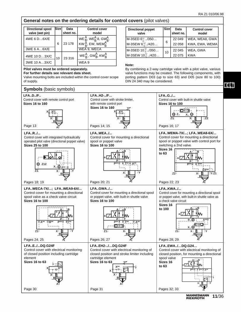
Note:By combining a 2-way cartridge valve with a pilot valve, variousvalve functions may be created. The following components, withporting pattern D03 (up to size 63) and D05 (size 80 to 100)DIN 24 340 may be considered.
Pilot valves must be ordered separately.For further details see relevant data sheet.Valve mounting bolts are included within the control cover scopeof supply.
General notes on the ordering details for control covers (pilot valves)
XB
A
Z1Z.. X..
Z2
XB
A
Z1
Z12X..
YF**
Symbols (basic symbols)LFA..D../F..Control cover with remote control portSizes 16 to 160
LFA..G../...Control cover with built-in shuttle valveSizes 16 to 100
LFA..H2-../F...Control cover with stroke limiter,with remote control portSizes 16 to 160
X**X
XB
A
X**X
XB
A
LFA..R../...Control cover with integrated hydraulicallyoperated pilot valve (directional poppet valve)Sizes 25 to 100
LFA..WEMA-7X/...; LFA..WEA8-6X/...Control cover for mounting a directionalspool or poppet valve with control port forswitching a 2nd valveSizes 16to 63
XB
A
Y
A
a
B
P TP** T**
F**Z2 Z1X
B
A
Y
A
a
B
P TP** T** A**
LFA..WECA-7X/...; LFA..WEA9-6X/...Control cover for mounting a directionalspool valve as a check valve circuitSizes 16 to 100
LFA..KWA../...Control cover for mounting a directional spoolor poppet valve, with built-in shuttle valve asa check valve circuitSizes 16to 100
LFA..GWA../...Control cover for mounting a directional spoolor poppet valve, with built-in shuttle valveSizes 16 to 100
XB
A
Y
A
a
B
P TP** T**A** B**
Z1 XB
A
Y
A
a
B
P TP** T** A**
Z1B
A
Y
A
a
B
P TP.. A**
Z1X..
X
LFA..E../...DQ.G24FControl cover with electrical monitoringof closed position including cartridgeelementSizes 16 to 63
LFA..EH2-../…DQ.G24FControl cover with electrical monitoring ofclosed position and stroke limiter includingcartridge elementSizes 16 to 63
X**X
XB
A
X**X
XB
A XB
A
Y
A
a
B
P TP** T** A**
LFA..WEA../...Control cover for mounting a directionalspool or poppet valveSizes 16 to 100
Control cover with electrical monitoring ofclosed position, for mounting a directionalspool valveSizes 16to 63
LFA..EWA../…DQ.G24…
Page 13 Pages 14; 15 Pages 16; 17
Pages 18; 19 Pages 20; 21 Pages 22; 23
Pages 24; 25 Pages 26; 27 Pages 28; 29
Page 30 Page 31 Pages 32; 33
AB
Size
4WE 6 D…6X/E WE , WE 8, GW ,
KW , EW, WEM
3WE 6 A…6X/E WEA 9, WECA
4WE 10 D…3X/C
3WE 10 A…3X/C WEA 9
Control covermodel
Directional spoolvalve (wet pin)
Datasheet no.
6 23 178
AB
AB
WE , GW , KWAB
AB
ABAB
AB
10 23 316
Size
M-3SED 6 ../350… 22 049 WEA, WEA8, GWA
M-3SEW 6 ../420… 22 058 KWA, EWA, WEMA
M-3SED 10 ../350… 22 045 WEA, GWA
M-3SEW 10 ../420… 22 075 KWA
Control covermodel
Directional poppetvalve
Datasheet no.
6
10
UCUCUCUC
RA 21 010/06.98
12/36
Standard Thread Part numberorifice for Orifice
size dia. inches (mm) M6 tapered M8 x 1 tapered G 3/8 G 1/2
R-ring 16 0.331 x 0.055 x 0.07 (8.41 x 1.4 x 1.78) 00025407 0002540825 0.386 x 0.059 x 0.07 (9.81 x 1.5 x 1.78) 00017453 0001761032 0.44 x 0.063 x 0.07 (11.18 x 1.6 x 1.78) 00017455 00017611
40, 50 0.504 x 0.095 x 0.103 (12.81 x 2.4 x 2.62) 00017457 0001761763 0.737 x 0.103 x 0.103 (18.72 x 2.62 x 2.62) 00024445 0002444680 1.046 x 0.139 x 0.139 (26.57 x 3.53 x 3.53) 00017466 00017630100 1.36 x 0.139 x 0.139 (34.52 x 3.53 x 3.53) 00017472 00017633
O-ring 125 1.609 x 0.139 (40.87 x 3.53) 00009376 00009505160 2.1 x 0.21 (53.35 x 5.33) 00009264 00009263
Thread Orifice - dia.inches (mm)
M6 taper 0.02 to 0.118(0.5 to 3.0)
M8x1 taper 0.03 to 0.158(0.8 to 4.0)
G 3/8 0.03 to 0.236(0.8 to 6.0)
G 1/2 0.039 to 0.315(1.0 to 8.0)
"G" pipe thread to ISO228/1
1) Possible orifice - diameterin relation to the thread size
Orifices - dia. in inches (mm) 1)
Pre
ssur
e di
ffere
ntia
l ∆p
in P
SI (
bar)
Dimensions of R-rings (O-rings) for ports X, Y, Z1, Z2 (included within the scope of supply)
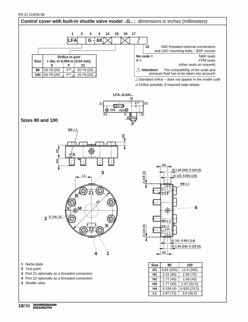
1 Name plate for sizes 16, 25, 322 Name plate for sizes 40, 50, 633 Port Z1 optionally as a threaded connection for size 634 Port Y optionally as a threaded connection for size 635 D1 for size 16 to 506 D1 for size 63
3) For orifice ordering details see page 11.4) Pressure in port Y max. 72.5 PSI (5 bar)
Area relationship =A Z1 3A X 1
RFLFA..R2-../..Sizes 25 to 50
LFA..R-../..Sizes 25 to 50
LFA63R2-6X/..Size 63
LFA63R-6X/..Size 63
4) 4) 4) 4)XB
A
Z1
Z12
Y
F**X..X
B
A
Z1
Z12
YF**
Z1
Y
X10X
B
A
Z1
Z12
YF**X..
XB
A
Z1
Z12
YF**
Z1
Y
X10
Standard orifice – does not appear in the model code
Orifice possible, if required state details1) 7X = series 7X (sizes 25, 32)
6X = series 6X (sizes 40, 50, 63)2) Directional poppet valve with spring return
Control cover wih integral poppet valve models ..R..; ..RF..; ..R2.. : dimensions in inches(millimeters)
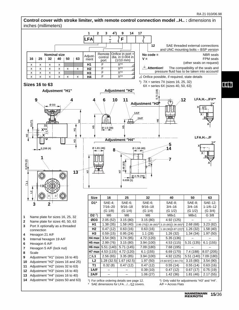
LFA –1 2 3 41) 14 15 16 17
Orifice in portSize Model + dia in 0.004 (1/10 mm)
X F Z125 R X0.39 (10) F** Z0.47 (12)32 R X0.47 (12) F** Z0.47 (12)40 R X0.59 (15) F** Z0.47 (12)50 R X0.59 (15) F** Z0.47 (12)63 R X0.71 (18) F** Z0.47 (12)25 RF2) X0.39 (10) F** Z0.47 (12)32 RF2) X0.47 (12) F** Z0.47 (12)40 R22) X0.59 (15) F** Z0.47 (12)50 R22) X0.59 (15) F** Z0.47 (12)63 R22) X0.71 (18) F** Z0.47 (12)
x x KWA A** P0.79 (20) T** X0.79 (20)x x KWB B** P0.79 (20) T** X0.79 (20)
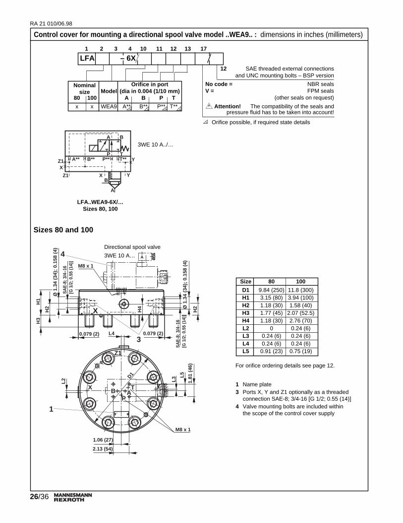
Nominalsize
1 2 3 4 10 11 12 13 14 17
LFA – 6X12 SAE threaded external connections
and UNC mounting bolts – BSP version
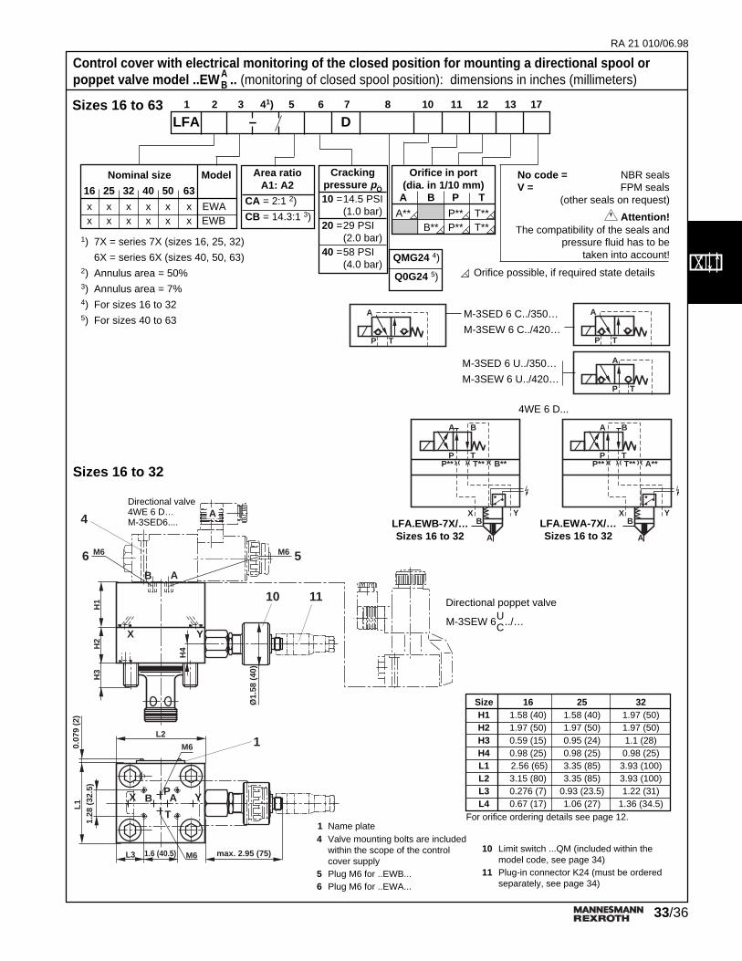
No code = NBR sealsV = FPM seals
(other seals on request)
Attention! The compatibility of the seals andpressure fluid has to be taken into account!
Orifice possible, if required state details
Standard orifice – does not appear in the model code
RA 21 010/06.98
31/36
X
XB
A
X**
Control cover with electrical monitoring of the closed position model ..E..(monitoring of closed spool position): dimensions in inches (millimeters)Technical data and notes are valid for all control covers withelectrical monitoring (..E.., ..EH2-.., ..EWA.., ..EWB..).
The solid state limit switch with integral amplifier switches when theclosed position is reached. This limit switch has the followingadvantages:
– No dynamic seals– Direct monitoring of the closed switched position of the valve– Long service life– Control cover and cartridge valve are included in the model
6) max. dim.For orifice ordering details see page 12.
LFA..EH2-7X/C...DQM...Sizes 16 to 32
X**
XX
B
A
X**X
XB
A
LFA..EH2-6X/C...DQ0...Sizes 40 to 63
Sizes 16 to 32 Sizes 40 to 63
Control cover with electrical monitoring of the closed position and stroke limitermodel ..EH2-.. (monitoring of closed spool position): dimensions in inches (millimeters)
1 Name plate3 Port X optionally as a threaded connection10 Limit switch ...QM (included within the
model code, see page 34)11 Plug-in connector K24 (must be ordered
separately, see page 34)12 Limit switch ...Q0 (included within the model
code, for electrical data see page 35)13 Plug-in connector (included within the
model code, supplied as loose item)14 Space required to remove plug-in connector15* For size 16 (length)
Orifice possible, if required state details1) 7X = series 7X (sizes 16, 25, 32)
6X = series 6X (sizes 40, 50, 63)2) Annulus area = 50%3) Annulus area = 7%4) For sizes 16 to 325) For sizes 40 to 63
No code = NBR sealsV = FPM seals
(other seals on request)
Attention!The compatibility of the seals and pressure
fluid has to be taken into account!
Nominal size
16 25 32 40 50 63
x x x x x x
Area ratioA1:A2
CA = 2:1 2)
CB = 14.3:1 3)
Crackingpressure pÖ
10 =14.5 PSI1.0 bar
20 =29 PSI2.0 bar
40 =58 PSI4.0 bar
LFA EH2– D F1 2 3 41) 5 6 7 8 9 14 17
QMG24 4)
Q0G24 5)
Orifice inport (dia.in 0.004 in(1/10 mm)
X**
*
RA 21 010/06.98
33/36
A
H2
X
H1
H3
L11.
28 (
32.5
)
0.07
9 (2
)
X Y
T
PB A
1.6 (40.5)L3 M6
B A
M6 M6
H4
Y
M6
L2
1110
56
1
max. 2.95 (75)
4
Ø1.
58 (
40)
Sizes 16 to 32
Sizes 16 to 63
1 Name plate 4 Valve mounting bolts are included
within the scope of the controlcover supply
5 Plug M6 for ..EWB... 6 Plug M6 for ..EWA...
4WE 6 D...
Directional valve4WE 6 D…M-3SED6....
Control cover with electrical monitoring of the closed position for mounting a directional spool orpoppet valve model ..EW .. (monitoring of closed spool position): dimensions in inches (millimeters)A
B
1) 7X = series 7X (sizes 16, 25, 32)
6X = series 6X (sizes 40, 50, 63)2) Annulus area = 50%3) Annulus area = 7%4) For sizes 16 to 325) For sizes 40 to 63
Control cover with electrical monitoring of the closed position for mounting a directional spool orpoppet valve model ..EW .. (monitoring of closed spool position): dimensions in inches (millimeters)A