he Acroloop Catalog is organized to giveyou the information you need quickly andeasily.
• First, glance through our Acroloop CorporateProfile. The corporate profile outlines the capabilities that are available from Acroloop.
• Second, scan the product index. The productindex pictorially previews the products availableand tells you where to find them.
• Next, take a moment to look over the selectionguide. The selection guide provides you with aneasy, visual, step-by-step approach to help buildthe perfect motion control system.
• Finally, the product catalog has detailedoutlines of the products and services availablefrom Acroloop.
If you don’t see what you need or if you need additional help, contact Acroloop for assistance. An Acroloop applications engineer will assist youor redirect you to the local technical office that canhelp you solve your motion control needs.
T
ACROLOOPMOTION CONTROL SYSTEMS, INC.
3
APPLICATIONS ASSISTANCE
Acroloop offers applications engineering assistance. Ifyou have a motion control application, contact Acroloopto discuss your needs with one of our engineers.Acroloop Applications Engineers are technical specialiststhat work with motion control applications involvingcomplex industrial projects or products with exactingtechnical specifications on a daily basis. We’ll be glad toput our motion control knowledge to work and help solveyour problems.
Acroloop also offers individual, technical brochuresthat describe the intricacies ofthe products available fromAcroloop. These productbrochures complement thisproduct catalog.
In addition, Acroloop maintains a national and international network of factory trained manufacturersrepresentatives, distributors, and value-added resellers.The main function of these organizations is to help youwith motion applications while providing local technicalsupport.
Manufacturers Representatives (MR’s)Acroloop has developed a network of MR’s across thecountry. The Acroloop MR’s are factory trained and possess years of industrial motion control experience.
Acroloop MR’s are particularly effective in solving complex motion control applications, especially wherehands on intimate knowledge must be maintainedbetween the customer needs and the Acroloop productsand services required to meet the application. AcroloopMR’s have exclusive territories in which they service ourcustomers, support distribution and our VARs.
ApplicationsEngineeringAssistance
Individual, TechnicalBrochuresAvailable
DistributorsAcroloop also maintains a nationwide network offactory trained distributors. Acroloop distributors typically represent a number of complimentary productlines for a wide variety of applications. Acroloop distributors function in two main ways:
• First, to provide local technical support to Acroloop customers similar to that provided by manufacturers representatives.
• Second, to provide ongoing support for territory re-purchase of Acroloop products. Acroloop distributors will maintain an inventory of Acroloopproducts locally when the demand for specific products in the territory exists.
Thus, Acroloop distributors can provide localtechnical support, inventory management and parts support to help better serve the needs of our customers.
Value-Added Resellers (VAR’s) Acroloop also maintains a network of VARs. In general, an Acroloop VAR can provide local integration services in the form of engineering, programming, technical support, on-site training, andstart-up assistance. Obviously, Acroloop also providesthese services, but a VAR is essential when the application requires a local technical integration specialist.
An approved Acroloop VARhas undergone extensive andongoing training at the factory in order to becomefamiliar with the types ofengineering issues that arisein applying Acroloop controllers and products.Contact Acroloop for a list ofapproved Acroloop VAR’s.
KnowledgeableManufacturers
Representatives
Nationwide, FactoryTrained Distributors
VAR:Local Technical
Integration Specialists
ACROLOOP MOTION CONTROL SYSTEMS4
MOTION CONTROLLERSACR Family of ControlsSelection Guide: page 6Product Catalog: pages 24-35
TURNKEY SYSTEMAcroloop or an Acroloop approved Value-Added Reseller (VAR) can packageall the components in a panel and providestart-up assistance.Product Catalogs: page 52
Building the Perfect Systemhere are six main product categories to consider when designing your motion control system. These categoriesare outlined below. The outline visually shows the products that are available from Acroloop and where tolocate them throughout the Selection Guide and the Product Catalog.T
5
ACROLOOP PRODUCT INDEX
ACROLOOP MOTION CONTROL SYSTEMS
he selection guide is an easy, visual, step-by-step tour to help you build the perfect motion control system. From components to integrated systems, the Selection Guide is designed to help you visualize exactly what you need for your motion control application.
The controller is the single most important element in motion control. There are a wide variety of issues to consider. However, the basic requirements consist of:
• Number of axes • Communications interface requirement• Type of motion control • Input/Output requirements
T
Additional technical information is available in the Motion Controllers section of this catalog. Additional technical assistance and information can also be obtained from Acroloop or the local representative.
Interface Binary, ASCII Binary, ASCII Binary, ASCII Binary, ASCII Binary, ASCIICOM1, COM2 Serial YES, Optional YES, Optional YES, Optional NO YES, StandardAcroWire IEEE-1394 Option YES, Optional YES, Optional YES, Optional NO YES, OptionalStandalone Option N/A YES YES NO YESPC-Bus Pluggable YES, PCI YES, ISA YES, ISA YES, ISA N/AParallel (LPT) Option YES YES YES NO YESDual Port Memory Option YES, Standard YES, Optional NO NO N/ABus Mastering YES NO NO NO N/A
Inputs/Outputs
Encoder Inputs 4-10 (Expandable) 4-10 2-4 2-4 3Encoder fault Detection YES, in hardware YES, in hardware NO NO YES, in hardwareAbsolute Encoder Option YES YES YES YES YESD/A Outputs 2-8 (Expandable) 2-8 2-4 2-4 2Uncommitted I/O 64 (Exp. to 320) 64 (Exp. to 320) 32 (Exp. to 288) 48 32 (Exp. to 160)I/O Type 24V Opto Isolated 24V Opto Isolated 24V Opto Isolated TTL 24V Opto IsolatedI/O Active Hi/Lo Select YES YES YES YES YESAUX Analog Inputs 8 SingleEnded/4 Differential 12 or 16 Bits 12 or 16 Bits 12 Bits 12 or 16 Bits 12 or 16 Bits
Model ACR8020 ACR8010 ACR2000 ACR1500 ACR1200
Step 1 - Selection of Controller
6
Selection Guide
This is a diagnostic and programming tool that allowsdevelopers to communicate to all Acroloop controllers inPC-Bus, Serial or Acrowire IEEE-1394 applications.This software allows project based program design formotion and graphical ladder logic IEC1131 PLC programming.
CNC Machine Tool Software program standard RS-274Dprogramming language. This software is offered for DOSas well as Windows. Can cycles, work coordinates,macros, parametric programming, cutter compensation isstandard.
The Acroloop Software Development Kit (SDK) allows customers to develop their own application very rapidly.Source code samples are provided in the SDK for visualBasic and Visual C++.
Step 2 - Selection of Software Tools
Let Acroloop or an Acroloop VAR modify one of yourexisting application software programs to your specification.
AcroView
AcroMill/AcroCut
Customer Written Application using Acroloop SDK
Custom Applications
7
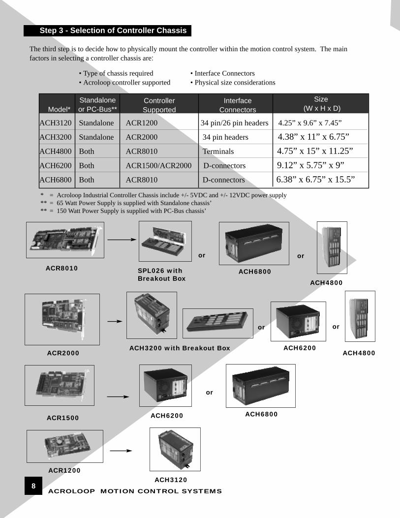
ACH3120 Standalone ACR1200 34 pin/26 pin headers 4.25” x 9.6” x 7.45”
ACH3200 Standalone ACR2000 34 pin headers 4.38” x 11” x 6.75”ACH4800 Both ACR8010 Terminals 4.75” x 15” x 11.25”ACH6200 Both ACR1500/ACR2000 D-connectors 9.12” x 5.75” x 9”ACH6800 Both ACR8010 D-connectors 6.38” x 6.75” x 15.5”
ACROLOOP MOTION CONTROL SYSTEMS
ACH6800ACH4800
ACR8010 SPL026 withBreakout Box
ACR1500
The third step is to decide how to physically mount the controller within the motion control system. The main factors in selecting a controller chassis are:
oror
* = Acroloop Industrial Controller Chassis include +/- 5VDC and +/- 12VDC power supply** = 65 Watt Power Supply is supplied with Standalone chassis’** = 150 Watt Power Supply is supplied with PC-Bus chassis’
ACR2000ACH6200
ACH4800ACH3200 with Breakout Box
oror
• Type of chassis required• Acroloop controller supported
OPS9200 PC/CNC 14” Color CRT Tactile 19” x 15.75” x 14.5” 120VAC
OPS9210 PC/CNC 12.1” Color LCD Tactile 19” x 12.25” x 4” 120VAC
OPS9220 PC/CNC 12.1” Color LCD Full 90 Key 19” x 17.5” x 4” 120VAC
OPS9000 PC 14” Color CRT Membrane 19” x 15.75” x 14.5” 120VAC
OPS8200 PC 10” Flat Panel** Touchscreen 12” x 10.5” x 8.5” 120VAC
OPS8220 PC 12.1” Color CRT Full 90 Key 19” x 17.5” x 10.75” 120VAC
OPS8100 PC 10” Flat Panel** Tactile 19” x 10.5” x 10.5” 120VAC
OPS8000 Smart 4x40 LCD Membrane 10.3” x 6.6” x 3.1” +/-12 & 5VDC
OPS1200 Smart 4x40 LCD Membrane 10.3” x 6.6” x 3.1” +/-12 & 5VDC
OPS1000 Smart 2x20 LCD Membrane 6.25” x 9.38” x 2” +/-12 & 5VDC
KBD 16 Dumb 1x16 LCD Membrane 7.1” x 4.1” x 1.1” 5VDC
• Number and Type of Keys• Interface requirements and operating system
• Application, physical constraints, and aesthetics• Cost Sensitivity
OPS9220
CPU Card + VGAACR8010
ACH4800
* = Acroloop Operator Interfaces are all NEMA 12 and can be panel or pendant mounted** = Flat Panel display can be LCD, EL, Passive Color or Active Color
Acroloop carries four main types of operator interfaces. The main question is to decide what information needs to be displayed and communicated to the operator. When deciding on the operator interface, the main factors are:
and
Step 4 - Selection of Operator Interface
9
Model*Interface
TypeDisplayType
Size(W x H x D)
KeyboardType
PowerRequirements
ACROLOOP MOTION CONTROL SYSTEMS
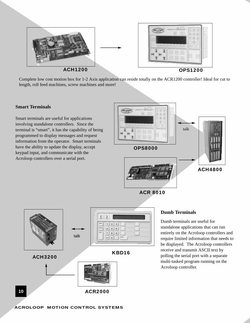
Smart Terminals
Smart terminals are useful for applicationsinvolving standalone controllers. Since the terminal is “smart”, it has the capability of beingprogrammed to display messages and requestinformation from the operator. Smart terminalshave the ability to update the display, acceptkeypad input, and communicate with the Acroloop controllers over a serial port.
Dumb Terminals
Dumb terminals are useful forstandalone applications that can runentirely on the Acroloop controllers andrequire limited information that needs tobe displayed. The Acroloop controllersreceive and transmit ASCII text bypolling the serial port with a separatemulti-tasked program running on theAcroloop controller.
talk
talk
ACH4800
OPS8000
ACR 8010
KBD16
ACR2000
Complete low cost motion box for 1-2 Axis application can reside totally on the ACR1200 controller! Ideal for cut tolength, roll feed machines, screw machines and more!
OPS1200ACH1200
ACH3200
10
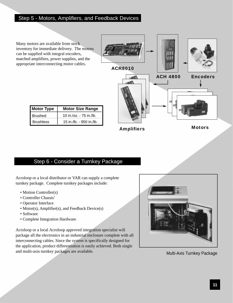
Step 5 - Motors, Amplifiers, and Feedback Devices
ACH 4800 Encoders
MotorsAmplifiers
ACR8010
Motor Type Motor Size RangeBrushedBrushless
10 in./oz. - 75 in./lb.15 in./lb. - 950 in./lb.
Many motors are available from stock inventory for immediate delivery. The motorscan be supplied with integral encoders,matched amplifiers, power supplies, and theappropriate interconnecting motor cables.
Acroloop or a local distributor or VAR can supply a complete turnkey package. Complete turnkey packages include:
Acroloop or a local Acroloop approved integration specialist willpackage all the electronics in an industrial enclosure complete with allinterconnecting cables. Since the system is specifically designed forthe application, product differentiation is easily achieved. Both singleand multi-axis turnkey packages are available. Multi-Axis Turnkey Package
Step 6 - Consider a Turnkey Package
11
ACROLOOP MOTION CONTROL SYSTEMS
Unique Features:
• 32/64 Bit Floating Point DSP
• On-the-Fly High Speed Trajectories
• Pre-Emptive Multi-Tasker
• Service up to 4 Comm. Channels Simultaneously
• Floating Point Electronic Gearing
• Automatic Rollover for No Cumulative Error
• Real Time Phase Advanced on Gears, Cams or Jog
• 50 usec Servo Update Time
• 200-500 usec (Addressable) Trajectory Loop Update Time
• Ladder Logic PLC
• Programmable Limit Switch with Multiple Sources for Initiation
• Hardware Position Registers
• On-Board Data Aqusition
• Optically Isolated I/O*
• Multi-Threaded Windows 98, NT Drivers
• Unlimited Data Array Size
• Complete Access to Variables Through Pre-mapped Parameters
Acroloop’s Family of Multi-axes Motion ControllersAt Acroloop Motion Control Systems, we have designed afamily of motion control cards that incorporate state-of-theart hardware, firmware, and software.
We believe that a high-end motion controller should beas small, flexible, and high-speed as possible, yet,remain affordable.
Highlighting the Floating Point DSPWe have designed our entire family of motion controllersusing high-speed Floating-Point Digital Signal Processors(DSP's). Floating-Point DSP's are the fastest, most accurateprocessors available today.
Acroloop uses the Texas Instrument TMS3203X DSP in allof the Acroloop family of Motion Controllers. The TI DSP simply outperforms non-DSP type processors in speed andaccuracy. The Acroloop family's DSP's vary from 40-150MHz, and have the ability to perform floating-pointcalculations on-board. This gives us an advantage over afixed-point DSP, or fixed-point Microprocessor-based controls. If a chip cannot perform floating point calculationson-board, then floating point calculations must be done insoftware.
Software calculations, instead of processor-based calculations, are typically updated at a much lower rate.This is one of the main reasons Acroloop's family ofcontrollers can process trajectory calculations so fast,typically in the 200-500 usec range (our competitors are typically in the 5000-8000 usec range).The ability to perform calculations on-board the floatingpoint DSP frees the controller to service a pre-emptive multi-tasker, with up to 24 programs atonce, and service up to four communication channelsconcurrently. This means you can communicate with anAcroloop controller for troubleshooting and still havethe HMI on a production machine fully on line andactive!
State of the Art ManufacturingOur commitment to product also extends to manufacturing.All cards from Acroloop described in this brochure aremanufactured as Dual Sided Surface Mount TechnologyCards on Acroloop’s own Surface Mount manufacturingline. This keeps the leadtimes short and insures quality.
All cards, after passing a test fixture, are burned-in atAcroloop’s test facility. In line with our commitment tobeing flexible, Acroloop controllers can be configured asstepper or servo in pairs. So you could have 2-axis ofservo, and 2-axis of stepper, with 2 encoder inputs on afour-axis ACR1500 controller card. The same softwareapplies to stepper or servo.
Common FirmwareAcroloop has common firmware for all the Acroloop familyof controllers. This means if you want to upgrade to afaster or larger card later, all of your development work willcarry over. Our firmware is infinitely flexible because it isparameter and flag based.
Any value such as commanded position, jog offset,ballscrew compensation, etc., is a parameter. This meansit can be the result of a parametric equation, or perhapsloaded off a spreadsheet or possibly changed on the flyas the result of a flag being set.
Development SoftwareDocumentation such as User Guides, Hardware orSoftware Manuals, Technical Brochures and SpecificationSheets are free on CD with any order. Our DevelopmentTool, Acroview, is also available free of charge with anyorder.
At Acroloop we embrace the trend towards Visual Basic,Visual C, or C++ Human Machine Interface. We also support many Soft PLC manufacturers as possible.Acroloop offers DLL's, Libraries and OCX's for variouswindows platforms.
13
ACROLOOP MOTION CONTROL SYSTEMS
Acroloop Controller Family
Windows NT
32 Bit Pre-Emptive Multi-Tasker
32 Bit Pre-Emptive Multi-Tasker
Multi-ThreadOperatingSystem
PC/PCIPC/ISAPC/CPCIPC/IEEE-1394*
Multi-ThreadOperatingSystem
Serial *
Serial *
Parallel *
MotionProgram
MotionProgram
PLCProgram
PLCProgram
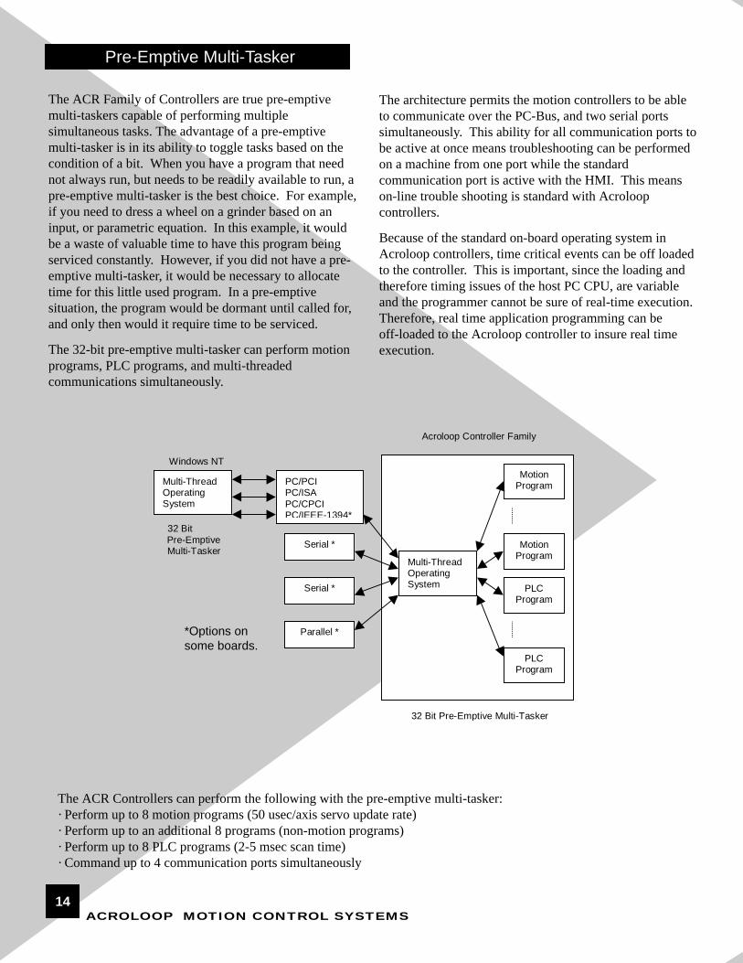
The ACR Controllers can perform the following with the pre-emptive multi-tasker:· Perform up to 8 motion programs (50 usec/axis servo update rate)· Perform up to an additional 8 programs (non-motion programs)· Perform up to 8 PLC programs (2-5 msec scan time)· Command up to 4 communication ports simultaneously
The ACR Family of Controllers are true pre-emptivemulti-taskers capable of performing multiplesimultaneous tasks. The advantage of a pre-emptivemulti-tasker is in its ability to toggle tasks based on thecondition of a bit. When you have a program that neednot always run, but needs to be readily available to run, apre-emptive multi-tasker is the best choice. For example,if you need to dress a wheel on a grinder based on aninput, or parametric equation. In this example, it wouldbe a waste of valuable time to have this program beingserviced constantly. However, if you did not have a pre-emptive multi-tasker, it would be necessary to allocatetime for this little used program. In a pre-emptivesituation, the program would be dormant until called for,and only then would it require time to be serviced.
The 32-bit pre-emptive multi-tasker can perform motionprograms, PLC programs, and multi-threadedcommunications simultaneously.
The architecture permits the motion controllers to be ableto communicate over the PC-Bus, and two serial portssimultaneously. This ability for all communication ports tobe active at once means troubleshooting can be performedon a machine from one port while the standardcommunication port is active with the HMI. This meanson-line trouble shooting is standard with Acroloopcontrollers.
Because of the standard on-board operating system inAcroloop controllers, time critical events can be off loadedto the controller. This is important, since the loading andtherefore timing issues of the host PC CPU, are variableand the programmer cannot be sure of real-time execution.Therefore, real time application programming can be off-loaded to the Acroloop controller to insure real timeexecution.
*Options onsome boards.
Pre-Emptive Multi-Tasker
14
2 64 5,000
4 64 3,333
6 64 2,500
8 64 2,000
The Acroloop Motion Controllers can be set up toaccommodate stepper or servo analog outputs. Thecontrollers can be configured in combinations explainedin the ordering matrix on pages 34-35 of this brochure.Analog inputs at 12 or 16-bit resolutions are availableas options. These may be field configured as single-ended or differential inputs.
The architecture of the Acroloop controllers permitsnot only pre-emptive multi-tasking, but also highly accurate trajectory calculations. The Controllers areunique since they calculate a new trajectory pointevery interrupt. A new trajectory point is calculatedevery 200-1000 microseconds, depending on the userprogrammed interrupt period. Comparatively, other“high performance” motion controllers on the market calculate trajectories at a 5-10 millisecond rate.Thus, the Acroloop controller is an “order of magnitude” better with floating point calculations.
All of the trajectory calculations are performed on-board and calculated with a floating point processor. Based on a servo loop update time of 50microseconds per axis, the servo update time for 2 axesis 100 microseconds. By adding an additional 100microseconds for “overhead” tasks (PLC programs,communications, etc.), the total interrupt period is100usec + 100usec = 200usec. The trajectory calculation is then the inverse of 200 microseconds or5,000 points per second.
Calculating a new trajectory every interrupt is the methodof choice when the process consists of normal motiongeometry’s (i.e. lines and arcs). In PC-Bus applications,the controllers perform the trajectory calculations withouthost intervention. The host simply sends the appropriatecoordinate information to the Acroloop controller.
Number Calculation 40-150 MHzof Axis Bits Points/Second
ACROLOOP MOTION CONTROL SYSTEMS
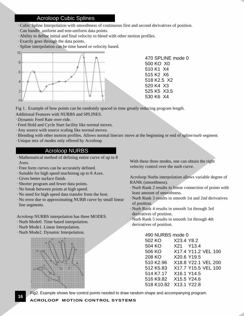
· Mathematical method of defining entire curve of up to 8 Axes.
· Free form curves can be accurately defined.· Suitable for high speed machining up to 8 Axes.· Gives better surface finish.· Shorter program and fewer data points.· No break between points at high speed.· No need for high speed data transfer from the host.· No error due to approximating NURB curve by small linear line segments.
Acroloop NURBS interpolation has three MODES.· Nurb Mode0. Time based interpolation. · Nurb Mode1. Linear Interpolation.· Nurb Mode2. Dynamic Interpolation. 490 NURBS mode 0
502 KO X23.4 Y8.2504 KO X21 Y13.4506 KO X17.4 Y11.2 VEL 100208 KO X20.6 Y19.5510 K2.96 X18.8 Y22.1 VEL 200512 K5.83 X17.7 Y15.5 VEL 100514 K7.17 X16.1 Y14.5516 K9.82 X15.5 Y24.6518 K10.82 X13.1 Y22.8
· Cubic Spline Interpolation with smoothness of continuous first and second derivatives of position.· Can handle uniform and non-uniform data points.· Ability to define initial and final velocity to blend with other motion profiles.· Exactly goes through the data points.· Spline interpolation can be time based or velocity based.
With these three modes, one can obtain the right velocity control over the nurb curve.
Acroloop Nurbs interpolation allows variable degree ofRANK (smoothness).· Nurb Rank 2 results in linear connection of points with least amount of smoothness.
· Nurb Rank 3 results in smooth 1st and 2nd derivatives of position.
· Nurb Rank 4 results in smooth 1st through 3rd derivatives of position.
· Nurb Rank 5 results in smooth 1st through 4th derivatives of position.
Fig 1. Example of how points can be randomly spaced in time greatly reducing program length.Additional Features with NURBS and SPLINES.· Dynamic Feed Rate over-ride.· Feed Hold and Cycle Start facility like normal moves.· Any source with source scaling like normal moves.· Blending with other motion profiles. Allows normal line/arc move at the beginning or end of spline/nurb segment.· Unique mix of modes only offered by Acroloop.
Fig2. Example shows few control points needed to draw random shape and accompanying program.
Acroloop Cubic Splines
Acroloop NURBS
16
CPU Card
ACR2000
PC-Bus PortBinary ASCII
PC-Bus
Floating Point Mathematics PrecisionAs previously discussed, the Acroloop Controllers areengineered around the Texas Instruments TMS320C3XFloating Point CPU. The controllers are also provided with64-bit precision floating point math functions. Compare the32-bit and 64-bit precision floating point variables to othermotion controllers; you won’t get rounding errors with theAcroloop Controllers. For example, a simpleelectronic gearing ratio can be set to a floating pointnumber unlike other controllers with limited gear ratioranges.
The Acroloop controller family is supplied with a 64 bitFloating Point Math Library. The Texas InstrumentsTMS320C3X uses 6 “decimal” digit numbers as standardto provide 32 bit accuracy. The Acroloop Controllers use16 “decimal” digit floating point numbers to providegreater accuracy. For example, you can represent the distance between the Earth and the Sun to a precision ofabout 20 miles with a 6 “decimal” digit number. The samedistance can be represented to a precision of 1/1000th of aninch with the 16 “decimal” digit number in the
Acroloop Controllers. The superior design of the processor permits the FloatingPoint Library to be installed on-board. The same FloatingPoint Library cannot be installed on other motion controllers due to their limited design and architectural features. With the Floating Point Library installed on theAcroloop Controllers, a full complement of parametricevaluations is possible.
The built-in floating point evaluator operates on bothglobal and local variables programmed in the Acroloopcontroller family. Unlike other motion controllers, theintermediate calculations for trajectories, parametric evaluations, PLC operations, high speed position captures,and many other tasks can all be performed simultaneouslyon the Acroloop controller without host intervention. If aPC host is required, it only requires updating the graphicaldisplay and feeding new operator information to the motioncontroller; the Acroloop controllers take care of everythingelse.
Simultaneous Port AccessThe Acroloop controllers are unique since they cancommunicate both ASCII and Binary simultaneously. Thesimultaneous access ports permit unrestricted integration offront end software designs. Typically, the ASCII scheme is usedfor traditional serial communications in standalone situations.Simple ASCII codes can be transmitted to the board over any ofthe on-board communications ports (COM1,COM2, LPT, andthe PC-BUS). However, the ASCII port on the PC-Bus port is critical in PC-Bus applications. The Binary port is used to handle the coordinate system data while the ASCII port is leftopen for additional communication that may require bypassingthe Binary interface port. The Acroloop design allows 2 accessdoors to the Acroloop Controllers simultaneously.
The second door is open for bi-directionalcommunications to and from the controller to theCPU.
In typical PC-Bus applications, the high speed datacommunications use the binary interface. A binaryinterface allows communications to occur in “coded”form. By using the “coded” form, communicationscan be increased dramatically to allow increased datathroughput to and from the controllers. As astandard feature, the Acroloop controller family has2 on-board high speed FIFO buffers to form aqueuing system for the data from the host processor.
17
ACROLOOP MOTION CONTROL SYSTEMS
Acroloop Controller Firmware Design
The Acroloop firmware is structured into specific objectgroups. Each group has a function and consists of similarcommands. The firmware design lets the user tailor theboard to the application. Consider the operating systemgroup.
The Operating System group is capable of handling up to8 coordinate systems.The coordinate systems are referred to as MASTER.Each MASTER is an independent motion profiler. EachMASTER can have up to 8 SLAVE’s. A slave is themodel for an AXIS. A set of axes is dependent on theMASTER for the profile velocity, acceleration, and deceleration parameters.
The declarations for a 3-axis system with dual loop feedback on the X-Y axis are:
In general, any combination of encoder, analog, stepper,and DAC output/input combinations can be attached to anaxis. The only restrictions are how the board isconfigured from a hardware standpoint.
Additional firmware commands are available to performcomplex algorithms or dynamic control. Almost all motion controllers have some form of camming, gearing, and I/O control, but at Acroloop, eventhese general commands are taken to another level of performance. The Acroloop firmware commandsinclude:
• Local Variables and Arrays - dynamic local program manipulation• Global Variables and Arrays - dynamic global program manipulation• String Variables and Arrays - full complement of string handling commands• Segmented Electronic Cam - position and velocity matching mode• Floating Point Electronic Gearing - velocity matching mode• Programmable Limit Switch - Digital I/O control (200-500 microsecond scan time)• Ladder Logic PLC - Multi-tasked PLC control (2-5 millisecond scan time)• Cubic Splines Interpolation• NURBS Interpolation• 3D Arc Interpolation• Sinusoidal Commutation• Time Based Moves
Acroloop firmware is “OBJECT” based. This makes programming and diagnosing very easy to accomplish. As an example, take the COMMUTATION objects CMT0, CMT1...CMT7. These 8 objects are responsible to software commutate motor windings if the user chooses to use them. To set control parameters, the user can simply address theobject properties in easy to understand commands. The following properties come up as default with the commutatorturned off.
18
Command Description
ATTACH MASTER0 REM: Setup profiler 0ATTACH SLAVE0 AXIS0 “X” REM: Setup the X axisATTACH SLAVE1 AXIS1 “Y” REM: Setup the Y axisATTACH SLAVE2 AXIS2 “Z” REM: Setup the Z axisATTACH AXIS0 ENC0 DAC0 ENC1 REM: Setup dual feedback for X axisATTACH AXIS1 ENC2 DAC1 ENC3 REM: Setup dual feedback for Y axisATTACH AXIS2 ENC4 DAC2 REM: Setup Z axis
Position Parameters Type MASTER0
Firmware Continued....
Object based programming is not only easy to program but it makes a big impact in diagnosing and debugging a program.
The Acroloop programming details are unique in their implementation. Compare these details before you buy! For acomplete detailed description of the commands and the firmware structure, contact Acroloop or your local sales office foran Acroloop Technical Brochure.
Hardware Parameter Access
The Acroloop firmware is implemented for infinite flexibility. The structure is a completelyopen design allowing the designer completeaccess to virtually every possible motion controlparameter and flag. As previously discussed,there are up to 8 MASTER’s and up to 8 axes ona motion controller. A master controls a group ofaxes. Thus, each MASTER has a unique groupof variables that can be monitored or changedon-the-fly.
Analyzing the tables, the vector velocity forMASTERprofiler 0 is stored in hardware parameter number P8193. Variable P8193 is a 32-bit floating point variable. If the programmerwanted to display the current position of AXIS0on the operator display, a request would be madeto the Acroloop controller to retrieve the 32-bitlong integer stored in hardware register P12288.There are approximately 15,000 different parameters pre-programmed into the Acroloopcontrollers.
Position Parameters Type AXIS0Current Position LONG P12288Target Position LONG P12289Actual Position LONG P12290Following Error LONG P12291Hardware Capture LONG P12292Software Capture LONG P12293Primary Setpoint LONG P12294Secondary Setpoint LONG P12295
Command DescriptionCMT0 OFF REM Commutator if Off.CMT0 ENC0 ENC1 REM Encoder Inputs used for commutation.CMT0 MODE 8 REM Mode is Trapezoidal then Sinusoidal.CMT0 ANG 120 REM Angle between windings is 120 degrees.CMT0 DAC0 DAC1 REM Dac outputs used for Phased Sine Outputs.CMT0 ADC0 ADC1 REM Optional ADC inputs used for current loop.CMT0 SHIFT0 REM Shift between marker and winding.CMT0 PPR 1024 REM Pulses per rev of the encoder.CMT0 ERPMR 2 REM Electrical revs per motor shaft revolution.CMT0 MAX RPM 0 REM Max allowable revolutions per minute.CMT0 MAX AMP 0 REM Max allowable AMPS into motor.
19
EXAMPLETARC OFF Default is TARC mode off.X1 Y-14 Z1 Position to start pointTARC ON X Y Z XYZ-axes are put to 3-D circular interpolation modeX13 Y-6 Z5 1st Arc intermediate pointX8 Y2 Z10 1st Arc end pointX5 Y6 Z-5 2nd ArcX10 Y2 Z-10 A2 A-axis will do linear coordinated move with XYZ-axesX0 Y0 Z-4.5 3rd Arc intermediate pointX-10 Y-2 Z1 3rd Arc end pointX1 Y3 Z15 4th ArcX-1 Y-2 Z1 This feature is not only limited to 3-D arcs. In 2-D, this is the simplest method of making an Arc. This command is asuperset of the 3 point circle generate function. This has tremendous advantages for digitizing and teaching applications.
In addition to the Spline and Nurb feature, the Acroloopcontrollers now offer Three Dimensional ArcInterpolation.
In 3-D machining, smart CAD systems have the ability tooutput 3-D arc segments to the CNC control. For this specific reason, Version 1.18.05 and above softwareallows user to specify 3-D Arcs (TARC command)directly into the controller. This command is used toselect any three of the axes attached to the master to do 3-dimensional circular interpolation. In this mode, the 3-D Arc is defined by a start point, an intermediate pointand an end point of the arc.
These points can be specified as incremental or absoluteposition. For successive 3-D Arcs, the end point of the arc is used as the start point of the next arc.
As required, any additional number of axes can be specifiedto the three-dimensional interpolation axes to perform acoordinated move.
The user simply specifies the start point, intermediate pointand the end point. There is no need to specify clockwise orcounterclockwise direction, since the controller canautomatically calculate the direction of rotation from user specified intermediate point.
3-D Arc Generation
20ACROLOOP MOTION CONTROL SYSTEMS
HSINTTarget
Win Start Window No Interrupt
Incremental Move
HardwareCapture
The purpose of the HSINT command is to give theprogrammer a way to initiate an incremental move based onan input. On webs, in particular, it is common to initiatemotion on the leading edge of a marker.
With this command one needs to define a target position, then a window. Once this is done, point toan input and when it goes to the correct state, it willinitiate the incremental move. This is all done at highspeed with one line of code.
The PLS command allows sequencing an Output Parameter(usually Physical I/O bits) based on the changing values of anInput Parameter (usually an encoder). The simplest form of a PLSis what is used in most "drum" sequencers in washing machines tocontrol various wash cycles. In the Acroloop PLS, the user canselect from a host of input and output parameters. Via software,the user can electronically advance and retard the sourceparameter, mask and scale the output parameter. Typically,Outputs are fired based on the position of a source encoder. Thiscan be done in conjunction with a CAMMING operation. TheMASK feature allows the user to allow the PLS to operate only onas many I/O bits as required. The firing sequence is programmedinto a Local Variable Array. The size of the array can be as long asavailable memory allows.
PLS SRC Set PLS sourcePLS BASE Attach array to PLSPLS ROTARY Set PLS rotary lengthPLS ROTARY Set PLS rotary lengthPLS ON Enable PLS updatePLS DST Set PLS destination pointerPLS RES Reset or pre-load counterPLS FLZ Set PLS index offsetPLS RATIO Set PLS Scaling ratioPLS OFF Disable PLS update
HSINT - High-Speed Interruptible Move
PLS - Programmable Limit Switch
Automatic Tangential Orientation
This feature automatically orients a cutting toolto a user set angle along an XY path. Ratherthen jump at discontinous geometries, thecontrol delays the next move and waits for thetool axes to orient.
TANG Z X Y ANG 90
The above command will hold the tool at 90degrees along the path shown.
Tangential Orientation
21
ACROLOOP MOTION CONTROL SYSTEMS
The CAM command is used as a replacementfor mechanical cam. The ability to segment theCAM gives the programmer flexibility. TheCAM profiler will automatically linearly interpolate between any two points no matterthe density of the points. The data for eachsegment of the CAM table resides in separatelong integer arrays, possibly of different sizes.This allows some parts of the table to bedefined coarsely, and others to be defined inmore detail.
CAM CommandsCAM DIM Allocate cam segmentsCAM SRC Redefine cam sourceCAM OFF Disable cam outputCAM OFFSET Set cam output offsetCAM SHIFT Set incremental cam shiftCAM SEG Define cam segmentsCAM ON Enable cam outputCAM SCALE Set cam output scalingCAM FLZ Set cam input offsetCAM RES Transfer cam offset
The TRG CAM command allows that a cam be started withalmost no following error or time delay. The advantage tothis type of move is the ability to negate the hysteresistypically associated with this type of move. For instance, ifa web line was moving at 60 ft/sec and there is a 2msec hysteresis before motion took place you can see by formulathat there will be an error of:
60ft/sec x 12in/ft = 720in/sec x .002sec = 1.44 inchesof error.
The TRG CAM command negates this and thereforeincreases repeatability and accuracy to within onemicrosecond. Barring mechanical limitations, the electronic accuracy is now reduced by a factor of 2000to 0.0007”!
Cam - Electronic Cam
TRG Cam - Triggered Cam
22
Once Velocity, Accel and Decel are set in the default settings, TMOV will calculate Velocity,Accel and Decel based on length and time of move.
Velocity
Accel Decel
The TMOV command was implemented to giveprogrammers an eloquent means of having moves becompleted in a specific amount of time. Previous toTMOV, the programmer would need to program with acalculator to determine the speed, acceleration anddeceleration needed to arrive at a destination in a specificamount of time.
With a constant time for moves the speed would need tobe different for every length of move and would have tobe recalculated. Now the Acroloop family of controllers solves your equation using TMOV. You needjust to decide the length and time of your move!
Occasionally it is necessary to run several coordinatedgroups of axis’ masters, in synchronization with anothermaster. For instance, in sewing, if a X-Y table is under aneedle, the table can only move when the needle is up outof the fabric. In this example the SYNC command can beused to coordinate the movement of the needle to themovement of the table.
Using SYNC moves, instead of coordinated moves,gives the flexibility of using different motion profiles for different masters, while still keeping them insync.
TMOV - Time Based Move
SYNC - Master Synchronizing
The figure above shows a velocity vs. time graph for five axes attached to different masters that move with independentaccelerations and decelerations yet are synchronized amongst themselves. They all complete their moves within theprescribed time interval of tmsec specified by the user. This mechanism can be useful in coil winding applications whenthe wire feed moves continuously, yet other axes must come and go at their own pace, but yet be synchronized to thewire feed.
23
ACROLOOP MOTION CONTROL SYSTEMS
Product Catalog MOTION CONTROLLERS
Our fastest most featured packed controller ever!(PCI, CPCI PC Bus Operation)
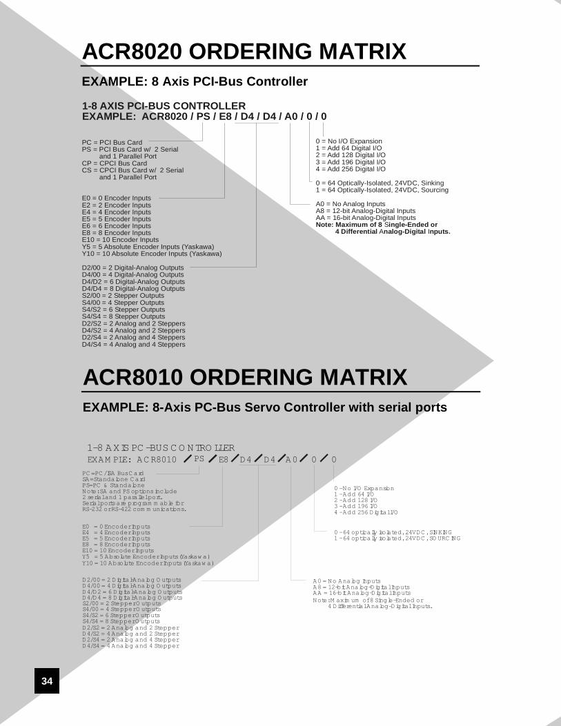
The ACR8020 is Acroloop Motion Control Systems’newest and most feature packed controller ever for PCI/CPCI PC Bus Operation. It has the ability to run 8 ServoLoops (16 with expansion board), DAC or Stepper outputsand 10 encoders (20 with expansion board) at 20Mhzcounting rate. It can also be equipped with 8 analog (12 or16 bit resolution) inputs. MultiAxis coordinated motioncan be performed in multiple groups of axes. Because ofour modular design, it is possible to have several axes ofservo mixed with stepper outputs on the same controller.All of the Acroloop Motion Control Systems’ controllersare software compatible so the standard features and benefits apply to the ACR8020.
As far as speed, the ACR8020 is unmatched in theindustry at 150MFLOPS!
ACR8020 Exclusives• 150 MHz floating Point DSP
• 8 Axes of Servo or Steppers Expandable to 16
• 10 Encoder Inputs at 20MHz Expandable to 20
• User and System Memory 512Kbytes (Expandable to 2 Mbytes) each
• Encoder Loss and Fault Protection
• 64 Optically Isolated 24VDC I/O Expandable to 320 I/O
• Dual Port Memory Standard
• Master PCI and CPCI DMA Interface
• Full size PCI and 6U CPCI Size
• Optional Parallel Port and 2-Serial RS232/RS422/RS485 or AcroWire (IEEE1394) Interface
ACR8020
24
HardwareAxes/controller 1-8 Axes (Expandable to 16)Communications PCI, CPCI BusProcessor 32/64 bit Floating Point
DSP @150MHzTrajectory Calc. 64-bit PrecisionUser Memory 512KB (expandable to 2 MB)System Memory 512KB (expandable to 2 MB)Firmware Flash BasedFlash Memory 512KB (expandable to 2 MB)Size Full size PCI, 6U CPCIOperating System Multitasking RTOS
CommunicationsPC Interface Bus Mastering PCI, CPCI
with Dual Port Memory
Inputs/OutputsEncoder Inputs 10 (expandable to 20) at
20MHzAnalog Outputs Up to 16 16-bit PrecisionStepper Outputs Up to 16 @ 4 MHz Digital I/O 64, 24V-DC
Position Reg. Hardware, < 1usecCommunications Simultaneous PCI, Serial and
LPT ports, AcroWire IEEE-1394
Software SupportStandard Lang. Visual Basic,C++,
Program Tools AcroVIEW Motion/PLC Program
Dev. Tools ActiveX ControlsOperating System Windows NT, 98, 2000
Additional Firmware Highlights:· Triggered Floating Point Electronic GEARING· Triggered Segmented Electronic CAM· On-the-fly Position and Velocity Matching· Ladder Logic PLC· Interruptible Moves· Either Analog or Digital Feedback for Position or Velocity Loops
· Dual Encoder Feedback· Teach and Learn Functions· Parameter Based with over 15,000 addressable Predefined Hardware Registers
Our fastest most featured packed controller ever!(Standalone or ISA PC Bus Operation)
The ACR8010 is Acroloop Motion Control Systems’newest and most featured packed controller for ISAPCBus Operation. The ACR8010 is capable ofStandalone or PC-Bus operation. It has the ability to runup to eight servo loops, with up to 10 encoders at 20MHz.It can optionally be equipped with 8 analog inputs througha 12 or 16 bit analog/digital converter and introduce theseinputs into servo loops. It is possible to have a VirtualAxis be the Master to multi-axis coordinated motion.Because of our modular design to our outputs, it ispossible to have several axis of servo with several axis ofstepper on the same controller. Of course all of AcroloopMotion Control Systems’ controllers run on the samesoftware and firmware, so the standard features andbenefits apply to the ACR8010 as well.
The ACR8010 is Acroloop Motion Control Systems’answer to affordable high performance control whenflexibility, real-time speed, and ease of programming aremost needed.
This product is the successor to the very popularACR8000 and offers plug compatibility with the olderproduct.
ACR8010 Exclusives• 8 axis of Servo or Stepper Control
• 60 MHz Floating Point DSP
• Up to 10 Encoder Inputs at 20MHz
• User and System Memory 512KBytes Standard (Each Expandable to 2 Mbytes)
• Encoder Loss and Encoder Fault Protection
• 64 Optically Isolated 24 VDC Inputs and Outputs (Expandable to 320 Optically Isolated 24 VDC Inputs and Outputs)
• Up to Four Communication Channels(PC Bus, 2 Serial RS-232/RS-422, 1Parallel Port)
• Calendar Clock Option
• Dual Port Memory Option
• Single Slot Plug & Play Controller
26
HardwareAxes/controller 1-8 axesCommunications PC-Bus or StandaloneProcessor 32/64 bit Floating Point
ProgramDev. Tools ActiveX/OCX controlsOperating System Windows NT, Windows
95/98, DOS
Additional Firmware Highlights:· Triggered Floating Point Electronic GEARING· Triggered Segmented Electronic CAM· On-the-fly position and velocity matching· Ladder Logic PLC· Programmable Limit Switch· Interruptible moves· Either analog or digital feedback for position or velocity loops
· Dual encoder feedback· Teach and Learn functions· Parameter based with over 15,000addressable pre-defined hardware registers
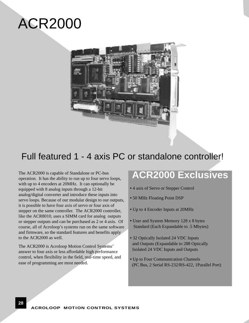
ACR2000 Exclusives• 4 axis of Servo or Stepper Control
• 50 MHz Floating Point DSP
• Up to 4 Encoder Inputs at 20MHz
• User and System Memory 128 x 8 bytes Standard (Each Expandable to .5 Mbytes)
• 32 Optically Isolated 24 VDC Inputs and Outputs (Expandable to 288 OpticallyIsolated 24 VDC Inputs and Outputs
• Up to Four Communication Channels(PC Bus, 2 Serial RS-232/RS-422, 1Parallel Port)
Full featured 1 - 4 axis PC or standalone controller!The ACR2000 is capable of Standalone or PC-bus operation. It has the ability to run up to four servo loops,with up to 4 encoders at 20MHz. It can optionally beequipped with 8 analog inputs through a 12-bitanalog/digital converter and introduce these inputs intoservo loops. Because of our modular design to our outputs,it is possible to have four axis of servo or four axis ofstepper on the same controller. The ACR2000 controller,like the ACR8010, uses a SIMM card for analog outputsor stepper outputs and can be purchased as 2 or 4 axis. Ofcourse, all of Acroloop’s systems run on the same softwareand firmware, so the standard features and benefits applyto the ACR2000 as well.
The ACR2000 is Acroloop Motion Control Systems’answer to four axis or less affordable high performancecontrol, when flexibility in the field, real-time speed, andease of programming are most needed.
28
ACR2000 SPECIFICATIONSHardwareAxes/controller 1-4 axesCommunications PC-Bus or StandaloneProcessor 32/64 bit Floating Point
DSP @50MHzTrajectory Calc. 64-bit precisionUser Memory 512KBytesSystem Memory 512KBytes Firmware Two 128K x 16 EPROM'sFlash Memory 512KBytes Size Half- size ISA boardOperating System Real time system
independent of PC
CommunicationsPC Interface Two 512 x 8 hardware
FIFO's Standalone Two Serial Ports (RS-232
and/or RS-422) One Parallel Port (8-bits)
Protocols Binary, String, & ASCII
Inputs/OutputsEncoder Inputs 4 (32-bit registers), 8 MHzAnalog Outputs up to 4, 16-bit precisionStepper Outputs up to 4, 4 MHz Digital I/O 32, 24VDC
optically-isolated (expandable to 320)
Auxiliary Analog Inputs up to 8 (12- bit)
PerformanceMulti-tasker 8 coordinate systems,
Motion/PLC programsTrajectory Update Every 200-500 micro
ProgramDev. Tools ActiveX/OCX controlsOperating System Windows NT, Windows
95/98, DOS
Additional Firmware Highlights:
· Triggered Floating Point Electronic GEARING· Triggered Segmented Electronic CAM· On-the-fly position and velocity matching· Ladder Logic PLC· Programmable Limit Switch· Interruptible moves· Either analog or digital feedback for position or velocity loops
· Dual encoder feedback· Mixing of Axes and interpolation· Teach and Learn functions· Parameter based with over 15,000addressable pre-defined hardware registers
· NURBS and Splines· Spherical Commands· Automatic Targential Tool Operation
29
ACROLOOP MOTION CONTROL SYSTEMS
ACR1500
OEM priced PC based ACR controller!
ACR1500 Exclusives• 4 Axis of Servo or Stepper Control
• 40 MHz Floating Point DSP
• 4 Encoder Inputs at 20MHz
• User and System Memory 128KBytes Standard
• 48 TTL I/O with an Industry Standard Opto 22, 50 Pin Connector
• Low Cost 16-bit Bus
• High Performance at a Low Cost
The ACR1500 is Acroloop Motion Control Systems’ newOEM 4-axis PC-Bus based controller. The ACR1500 is aPC-bus based card only and offers no serial or LPT ports asan option. It has the ability to run up to four servo loopswith up to 4 encoders at 20MHz. It can optionally beequipped with 8 analog inputs through a 12 or 16 bit analog/digital converter, and introduce these inputs into theservoloop. Because of our modular design to our outputs,it is possible to have two axis of servo with two axis ofstepper on the same controller or all of one type. Unlikethe Acroloop family of controllers the ACR1500 utilizes a16-bit bus, therefore, reducing cost dramatically. Until theACR1500, this level of control had been typically doublethe price! Of course, all of Acroloop’s systems run on thesame software and firmware, so the standard features andbenefits apply to the ACR1500 as well.
The ACR1500 is Acroloop Motion Control Systems’answer to affordable high performance control when lowcost, real-time speed, and ease of programming are mostneeded.
30
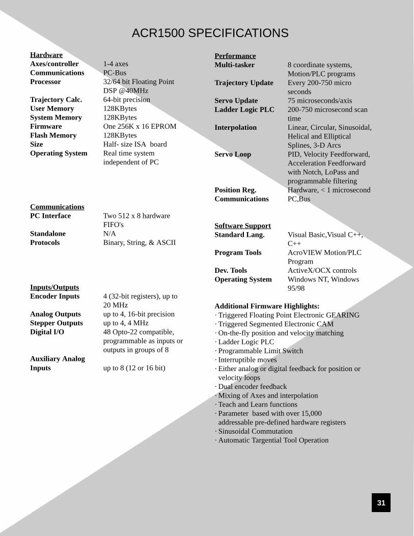
ACR1500 SPECIFICATIONSHardwareAxes/controller 1-4 axesCommunications PC-BusProcessor 32/64 bit Floating Point
DSP @40MHzTrajectory Calc. 64-bit precisionUser Memory 128KBytesSystem Memory 128KBytesFirmware One 256K x 16 EPROMFlash Memory 128KBytesSize Half- size ISA boardOperating System Real time system
ProgramDev. Tools ActiveX/OCX controlsOperating System Windows NT, Windows
95/98
Additional Firmware Highlights:· Triggered Floating Point Electronic GEARING· Triggered Segmented Electronic CAM· On-the-fly position and velocity matching· Ladder Logic PLC· Programmable Limit Switch· Interruptible moves· Either analog or digital feedback for position or velocity loops
· Dual encoder feedback· Mixing of Axes and interpolation· Teach and Learn functions· Parameter based with over 15,000addressable pre-defined hardware registers
The ACR1200 is Acroloop Motion Control Systems’ newOEM 2-axis standalone controller. The ACR1200 is astandalone controller card only and offers no PC port as anoption. The ACR1200 comes standard with two serialports, either RS-232 or RS-422. It has the ability to run upto two servo loops with up to 3 encoders at 20MHz. It canoptionally be equipped with 8 analog inputs through a 12 or16 bit analog/digital converter and introduce these inputsinto the servoloop. Because of our modular design to ouroutputs, it is possible to have one axis of servo with oneaxis of stepper on the same controller, or all of one type.Until the ACR1200, this level of control at our price had notbeen available. Of course, all of Acroloop’s systems runon the same software and firmware, so the standard featuresand benefits apply to the ACR1200 as well.
The ACR1200 is Acroloop Motion Control Systems’answer to affordable high performance standalone control,when low cost, real-time speed, and ease of programmingare most needed.
32
ACR1200 SPECIFICATIONS HardwareAxes/controller 1-2 axesCommunications StandaloneProcessor 32/64 bit Floating Point
ProgramDev. Tools ActiveX/OCX controlsOperating System Windows NT, Windows
95/98, DOS
Additional Firmware Highlights:· Floating Point Electronic GEARING· Segmented Electronic CAM· On-the-fly position and velocity matching· Ladder Logic PLC· Programmable Limit Switch· Interruptible moves· Either analog or digital feedback for position or velocity loops
· Dual encoder feedback· Mixing of Axes and interpolation· Teach and Learn functions· Parameter based with over 15,000addressable pre-defined hardware registers
PC =PC /ISA BusC ardSA -Standalone C ardPS= PC -Busand Standalone
Note: SA and PS options includecom m unications daughterboardwith 2 serial and 1 parallel port.Serial ports are program m able forRS-232 or RS-422 com m unications.
A0 = NO NE N/CA8 = 12 bitAnalog-DigitalInputs
Note: M ax of 8 Single-Ended or 4 Differential Analog-Digital Inputs
0 - 32 O ptically Isolated 24VDC , Sinking1 - 32 O ptically Isolated 24VDC , Sourcing
0E4 00 01-4 AXIS M O TIO N C O NTRO LLER
D2/00 = 2 Digital-Analog O utputsD4/00 = 4 Digital-Analog O utputsS2/00 = 2 Stepper O utputs S4/00 = 4 Stepper O utputs
35
ACROLOOP MOTION CONTROL SYSTEMS
DEVELOPMENT TOOLSThere are several development tools that are provided with theAcroloop controller family. The controllers can be provided with C++ libraries, Visual C libraries, or Visual Basiclibraries. Since the libraries are generically designed, thelibraries can be used for additional programming languages suchas Delphi. The development tools can be provided with driversfor Windows 98, Windows 2000 and Windows NT operatingsystems. With the development tools, the controllers can beintegrated into customized application software.
With the Acroloop Library, commands available on theAcroloop motion controller have a corresponding function call.Applications that are programmed on the PC simply use thefunction call provided in the library when the program needs touse the controller’s motion control capabilities. The Acroloopcontroller family can be supplied with the following libraries:• Visual C /C++ Dynamic Link Library (Windows98, 32-bit)• Visual C/C++ Libraries (Windows NT, 32-Bit
multi-threaded)• Visual Basic Dynamic Link Library (Windows98, 32-bit)• Visual Basic Dynamic Link Libraries (Windows NT, 32-bit
multi-threaded)Since the libraries are generically designed, the libraries can beused for additional programming languages such as Borland’sDelphi. With Delphi, the proper arguments must be programmed for the function call.
Visual C/C++ and Visual Basic DLL’s allow the programmerto easily customize a graphically orientated operator interface to work in conjunction with the Acroloop controllers. The Acroloop controllers support simultaneousbinary and ASCII interface schemes. The “double door”design allows complete access without worrying about congesting the port. Acroloop also supports WindowsNT,Windows 2000 and Windows 98 environments. TheWindows NT DLL’s can support multi-threaded applicationsrunning under Windows NT or Windows 98 and Windows 2000.
Acroloop Libraries
Product Catalog SOFTWARE
36
AcroVIEW is a development tool used tocommunicate to the motion controllers. AcroVIEWcan talk to the controllers either over the PC-BUS orRS-232 communications ports. AcroVIEW isprovided at no charge to help integrate, diagnose, andgraphically tune the Acroloop motion controllers.
AcroVIEW can also be used to debug customized PCapplications. Since the Acroloop controllers cancommunicate simultaneously, the API can be operating on the PC while AcroVIEW tool candynamically diagnose the Acroloop controller withAcroVIEW on the serial port. This saves valuabledevelopment time.
The AcroVIEW supplied software can also act as avaluable diagnostic tool. AcroVIEW can be used toenter in customized software programs and test thecontrollers on a bench before implementing thecontroller into a real world application. AcroVIEW permits the user to send and receive files to and fromthe controllers. In addition, AcroVIEW provides anon-screen real time display of the input and outputsstatus while the desired program is being executed.
Possibly the most important aspect of AcroVIEW is toallow the user to graphically tune the servo system.AcroVIEW provides a built-in oscilloscope so that theservo system can be tuned on the computer screen.This could either be accomplished through the parallelport or via a laptop computer at the installation site.Even if other development tools are being used (i.e.C++ Libraries or DLL’s), AcroVIEW can be run separately to insure that the system is tuned properly.
AcroVIEW
AcroVIEW-Diagnostics
AcroVIEW-Graphical Tuning
37
ACROLOOP MOTION CONTROL SYSTEMS
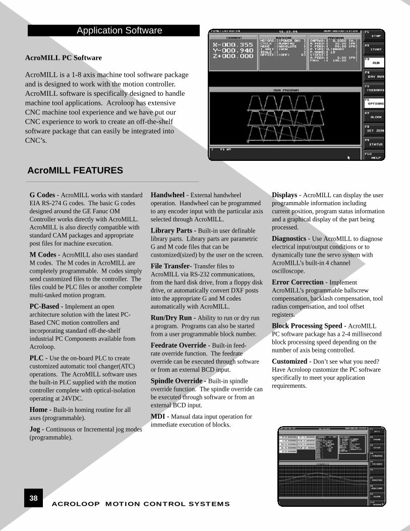
AcroMILL is a 1-8 axis machine tool software packageand is designed to work with the motion controller.AcroMILL software is specifically designed to handlemachine tool applications. Acroloop has extensiveCNC machine tool experience and we have put ourCNC experience to work to create an off-the-shelfsoftware package that can easily be integrated intoCNC’s.
AcroMILL PC Software
AcroMILL FEATURES
G Codes - AcroMILL works with standardEIA RS-274 G codes. The basic G codesdesigned around the GE Fanuc OMController works directly with AcroMILL.AcroMILL is also directly compatible withstandard CAM packages and appropriatepost files for machine execution.
M Codes - AcroMILL also uses standardM codes. The M codes in AcroMILL arecompletely programmable. M codes simplysend customized files to the controller. Thefiles could be PLC files or another completemulti-tasked motion program.
PC-Based - Implement an openarchitecture solution with the latest PC-Based CNC motion controllers andincorporating standard off-the-shelfindustrial PC Components available fromAcroloop.
PLC - Use the on-board PLC to createcustomized automatic tool changer(ATC)operations. The AcroMILL software usesthe built-in PLC supplied with the motioncontroller complete with optical-isolationoperating at 24VDC.
Home - Built-in homing routine for allaxes (programmable).
Jog - Continuous or Incremental jog modes(programmable).
Handwheel - External handwheeloperation. Handwheel can be programmedto any encoder input with the particular axisselected through AcroMILL.
Library Parts - Built-in user definablelibrary parts. Library parts are parametricG and M code files that can becustomized(sized) by the user on the screen.
File Transfer- Transfer files toAcroMILL via RS-232 communications,from the hard disk drive, from a floppy diskdrive, or automatically convert DXF postsinto the appropriate G and M codesautomatically with AcroMILL.
Run/Dry Run - Ability to run or dry runa program. Programs can also be startedfrom a user programmable block number.
Feedrate Override - Built-in feed-rate override function. The feedrateoverride can be executed through softwareor from an external BCD input.
Spindle Override - Built-in spindleoverride function. The spindle override canbe executed through software or from anexternal BCD input.
MDI - Manual data input operation forimmediate execution of blocks.
Displays - AcroMILL can display the userprogrammable information includingcurrent position, program status informationand a graphical display of the part beingprocessed.
Diagnostics - Use AcroMILL to diagnoseelectrical input/output conditions or todynamically tune the servo system withAcroMILL’s built-in 4 channeloscilloscope.
Block Processing Speed - AcroMILLPC software package has a 2-4 millisecondblock processing speed depending on thenumber of axis being controlled.
Customized - Don’t see what you need?Have Acroloop customize the PC softwarespecifically to meet your applicationrequirements.
Application Software
38
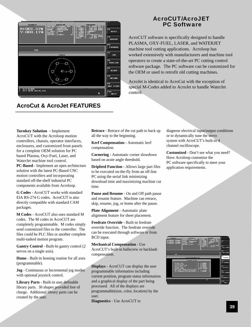
AcroCUT software is specifically designed to handlePLASMA, OXY-FUEL, LASER, and WATERJETmachine tool cutting applications. Acroloop has worked extensively with manufacturers and machine tooloperators to create a state-of-the-art PC cutting controlsoftware package. The PC software can be customized forthe OEM or used to retrofit old cutting machines.
AcroCUT/AcroJETPC Software
Turnkey Solution - ImplementAcroCUT with the Acroloop motioncontrollers, chassis, operator interfaces,enclosures, and customized front panelsfor a complete OEM solution for PCbased Plasma, Oxy-Fuel, Laser, andWaterJet machine tool control.PC-Based - Implement an open architecturesolution with the latest PC-Based CNCmotion controllers and incorporatingstandard off-the-shelf industrial PCcomponents available from Acroloop.
G Codes - AcroCUT works with standardEIA RS-274 G codes. AcroCUT is alsodirectly compatible with standard CAMpackages.
M Codes - AcroCUT also uses standard Mcodes. The M codes in AcroCUT arecompletely programmable. M codes simplysend customized files to the controller. Thefiles could be PLC files or another completemulti-tasked motion program.
Gantry Control - Built-In gantry control (2servos on a single axis).
Home - Built-in homing routine for all axes(programmable).
Jog - Continuous or Incremental jog modeswith optional joystick control.
Library Parts - Built-in user definablelibrary parts. 30 shapes provided free ofcharge. Additional library parts can becreated by the user.
Retrace - Retrace of the cut path to back upall the way to the beginning.
Kerf Compensation - Automatic kerfcompensation.
Cornering - Automatic corner slowdownbased on acute angle threshold.
Dripfeed Function - Allows large part filesto be executed on-the-fly from an off-linePC using the serial link minimizingdownload time and maximizing machine cuttime.
Pause and Resume - On and Off path pauseand resume feature. Machine can retrace,skip, resume, jog, or home after the pause.
Plate Alignment - Automatic platealignment feature for sheet placement.
Feedrate Override - Built-in feedrateoverride function. The feedrate overridecan be executed through software or fromBCD input.
Mechanical Compensation - UseAcroCUT’s built-in ballscrew or backlashcompensation.
Displays - AcroCUT can display the userprogrammable information includingcurrent position, program status informationand a graphical display of the part beingprocessed. All of the displays areprogrammable(size, color, location) by theuser.Diagnostics - Use AcroCUT to
diagnose electrical input/output conditionsor to dynamically tune the servo system with AcroCUT’s built-in 4 channel oscilloscope.
Customized - Don’t see what you need?Have Acroloop customize the PC software specifically to meet yourapplication requirements.
AcroJet is identical to AcroCut with the exception ofspecial M-Codes added to AcroJet to handle WaterJetcontrol.
39
AcroCut & AcroJet FEATURES
ACROLOOP MOTION CONTROL SYSTEMS
Main screen while running program.
Entering M.D.I. commands.
AcroMill and AcroCut are also offered in a WindowsNT based version. The main features are very similar tothe DOS versions of these programs but because of the multitasking ability of the operating system, manyenhancements are offered. The following screens showsome of the features. AcroMill for Windows NT isdesigned to work with a touch screen or a mouse.Therefore, all the menu selections are large enough toallow easy finger control and selection. New programscan be created while the machine is running a program.Full compliments of Can Cycles and Macro and ModalMacro ability is offered.
Probing cycle as well as NURBS, Splines and three dimensional 3 point arc generation is offered.
OEM users can access and pass variables in the SYSVARstorage area in the CNC from their own independent software application in case a custom installation is required.
This means that the OEM can externally affect machineoperation from their own piece of software on the fly. Thiscan be very handy in applications like vision, grinding,welding….etc.
AcroMill NT
40
Edit a program even while running a different program.
Setting up system parameters.
Jogging Screen.
41
ACROLOOP MOTION CONTROL SYSTEMS
Tuning axis servos using built-in 4 channel oscilloscope.
Monitoring I/O status while running apart.
Selecting library parts.
42
SPL026 Standalone BracketThe SPL026 is a standalone mounting bracket for the ACR8010. TheSPL026 is designed for integration of the motion controller into anindustrial enclosure. Typically, the standalone bracket is ordered witha breakout box.
SPL026 Features• Use with Standalone ACR8010 controller• Industrial Metal Bracket (14”W x 5.38”H x 1.63”D)• Mounts to Industrial Panel
SPL026 Standalone Bracketwith Breakout Box
RBD Breakout Box
RBD Breakout BoxThe RBD breakout box is designed to allow integration of the ACR2000,ACR8010, or ACR8020 motion controllers. The breakout box can beused in either standalone or PC-Bus applications. It is typically mountedto an industrial panel next to the motion controller.
RBD Breakout Box Feature• Use with either the ACR2000, ACR8010 or ACR8020 controllers• Industrial Breakout Box (4.75”W x 14.75”H x 1.25”D)• Screw terminations for encoder feedback• Screw terminations for digital I/O connections• 2 Serial and 1 Parallel Port DB Connectors• Status LED’s for encoder, digital I/O, and
communication diagnostics
The main factors in selecting a controller chassis are:• Type of controller used (ACR1200, ACR1500, ACR2000, ACR8010 or ACR8020)• Number of chassis slots required• Interface requirements• Physical considerations
ACH3120 Features• Use with ACR1200 Controller• Industrial Standalone Chassis• Encoder Feedback Connector• Digital I/O Connector• 2-Sided and 1 Parallel Port Connector• Heavy Duty Power Connector, 120 VAC• Integral Power Supply (5VDC, +/- 12VDC)• Cooling Fan IncludedACH3120
ACH3120 Controller ChassisThe ACH3120 controller chassis is a standard chassis. It is designed to accommodate a standaloneACR1200 controller. The ACH3120 is designed tosupport the standard digital I/O and 1 expansiondigital I/O board.
Product Catalog CONTROLLER CHASSIS
43
ACROLOOP MOTION CONTROL SYSTEMS
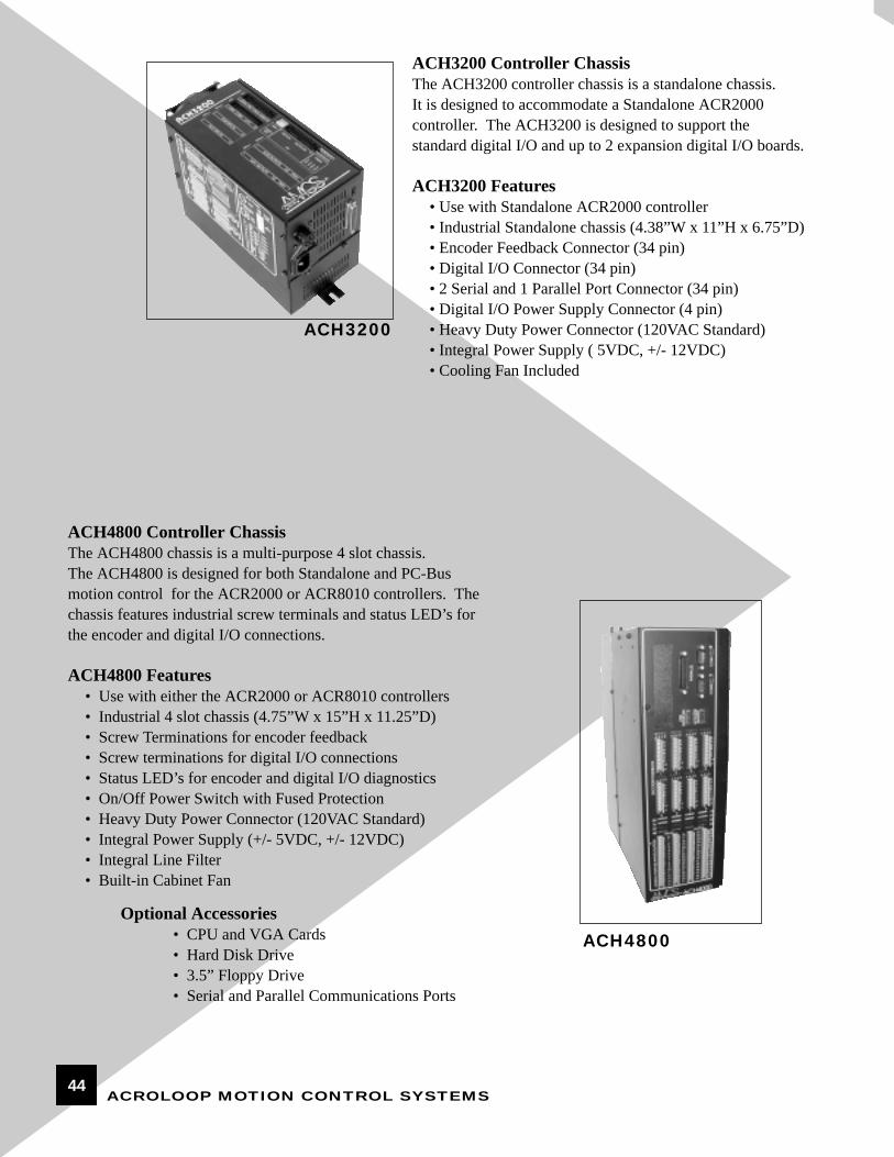
ACH3200 Controller ChassisThe ACH3200 controller chassis is a standalone chassis. It is designed to accommodate a Standalone ACR2000 controller. The ACH3200 is designed to support the standard digital I/O and up to 2 expansion digital I/O boards.
ACH3200 Features• Use with Standalone ACR2000 controller• Industrial Standalone chassis (4.38”W x 11”H x 6.75”D)• Encoder Feedback Connector (34 pin)• Digital I/O Connector (34 pin)• 2 Serial and 1 Parallel Port Connector (34 pin)• Digital I/O Power Supply Connector (4 pin)• Heavy Duty Power Connector (120VAC Standard)• Integral Power Supply ( 5VDC, +/- 12VDC)• Cooling Fan Included
ACH3200
ACH4800 Controller ChassisThe ACH4800 chassis is a multi-purpose 4 slot chassis. The ACH4800 is designed for both Standalone and PC-Busmotion control for the ACR2000 or ACR8010 controllers. Thechassis features industrial screw terminals and status LED’s forthe encoder and digital I/O connections.
ACH4800 Features• Use with either the ACR2000 or ACR8010 controllers• Industrial 4 slot chassis (4.75”W x 15”H x 11.25”D)• Screw Terminations for encoder feedback• Screw terminations for digital I/O connections• Status LED’s for encoder and digital I/O diagnostics• On/Off Power Switch with Fused Protection• Heavy Duty Power Connector (120VAC Standard)• Integral Power Supply (+/- 5VDC, +/- 12VDC)• Integral Line Filter• Built-in Cabinet Fan
Optional Accessories• CPU and VGA Cards• Hard Disk Drive• 3.5” Floppy Drive• Serial and Parallel Communications Ports
ACH4800
44
ACH6200 Controller ChassisThe ACH6200 chassis is also a multi-purpose 4 slot chassis. The main difference is the ACH6200 is designed forhalf-size PC boards. Therefore, it is ideal for applications where space is critical. The chassis is used with theACR2000 controller.
ACH6200
ACH6200 Features• Use with the ACR2000 controller• Industrial 4 slot chassis (9.12”W x 5.75H x 9”D)• D-plug connectors for encoder feedback• D-plug connectors for digital I/O connections• On/Off Power Switch• Heavy Duty Power Connector (120VAC Standard)• Integral Power Supply (+/- 5VDC, +/- 12VDC)• Built-in Cabinet Fan• CE Certified
Optional Accessories• CPU and VGA Cards• Hard Disk Drive• 3.5” Floppy Drive• Serial and Parallel Communications Ports
ACH6800 Controller ChassisThe ACH6800 chassis is a 6-slot multi-purpose chassis. The maindifference is it is a full size chassis and the connections are madeusing D-plug connectors. The ACH6800 is used for either standalone or PC-Bus applications.
ACH6800 Features• Use with either ACR2000 or ACR8010• Industrial 6-slot chassis (6.38”W x 6.75”H x 15.5”D)• D-plug connectors for encoder feedback• D-plug connectors for digital I/O connections• On/Off Power Switch• Heavy Duty Power Connector (120VAC Standard)• Integral Power Supply (+/- 5VDC, +/- 12VDC)• Integral Line Filter• Built-in Cabinet Fan
Optional Accessories• CPU and VGA Cards• Hard Disk Drive• 3.5” Floppy Drive• Serial and Parallel Communications Ports
ACH6800
45
ACROLOOP MOTION CONTROL SYSTEMS
OPS 9220
OPS8220All features of the OPS9220 plus:
• Full 6-Slot PC Chassis Mounted Behind Keyboard• On/Off switch with Integrated Power, HDD
and Reset LED • 2 RS-232 Serial Ports, 1 Parallel Port • 32 MEG RAM Standard, Expandable to 128 MEG • 19"W x 17.5"H x 10.75"D • Optional CPU and Video Types• Optional Floppy Disk and Hard Disc Drives
OPS8220
OPS9220• Industrial CNC NEMA 12 Interface Including:
• Spindle CCW, CW, OFF, and OVERRIDE Controls• Feedrate HOLD, START Controls• Feedrate Override Control• Rapid Override Control• E-STOP and RESET Pushbuttons• One AUXILIARY Pushbutton
• Use with Acroloop PC Chassis • 12.1" Active Matrix Color LCD Screen • NEMA 4 Full-size Keyboard • 19"W x 17.5"H x 4"D • Interfaces to Standard CPU and VGA Cards • Optional Pendant Enclosure • Optional Manual Pulse Generator Handwheel• Optional Touchscreen• Industrial Design for “One Step” Panel Mounting• Integrated Mouse Pad• Operates in Windows, DOS Environment
OPS9220 & OPS8220The OPS9220 is designed specifically for PC-Based CNC Machine Tool applications. It is typically integrated with anAcroloop controller and controller PC chassis. The OPS9220 integrates the PC monitor and keyboard with CNC spindle, feedrate, handwheel, and emergency stop controls.
Product Catalog OPERATOR INTERFACES
46
OPS9000The OPS9000 is another option for an industrial PCoperator interface. The only difference is the size ofthe monitor and the keyboard configuration. Again,the OPS9000 is integrated with an Acroloop controllerand PC controller chassis.
OPS9000 Features• Use with Acroloop PC Chassis• Industrial NEMA 12 Design• 14” Color CRT VGA Monitor• 84 Key Membrane Keyboard• 19”W x 15.75”H x 14.5”D• Panel or Pendant Mounted• Interfaces to standard CPU and VGA cards• Optional Pendant Enclosure
OPS9000
OPS8200The OPS8200 is a complete PC-Based system. The design features flat panel technology with an integral PC chassis. It is also compact since it is designed for 1/2 size PC cards. TheOPS8200 is ideal for applications requiring up to 4 axis ofmotion control and a compact design.
OPS8200 Features• Use with ACR2000 Controller• Industrial NEMA 12 Design• 10” Flat Panel LCD Screen• Touchscreen Interface • Integral 4 slot chassis includes:
• Industrial CPU Card with RAM• Industrial 64-bit VGA Driver • 3.5” Industrial Floppy Drive• 1 Gigabyte Industrial Hard Drive• 150 Watt Power Supply
• Compact Design (12”W x 10.5”H x 8.5”D)• Optional EL, Passive or Active Color Displays
OPS8100 Features• Use with ACR2000 or ACR8010 Controller• Industrial NEMA 12 Design• 10” Flat Panel LCD Screen• 83 or 43 Key Keyboard• Integral 6 slot chassis includes:
• Industrial CPU Card with RAM• Industrial 64-bit VGA Driver • 3.5” Industrial Floppy Drive• 1 Gigabyte Industrial Hard Drive• 150 Watt Power Supply
• Compact Design (19”W x 10.5”H x 10.5”D)• Optional EL, Passive or Active Color Displays• Optional Touchscreen Interface
OPS8100OPS8100The OPS8100 is similar to the OPS8200except that it includes a PC keyboard and afull size PC chassis. The OPS8100 is idealfor applications requiring up to 8 axis of PC-Based motion control all in a compactpackage.
OPS8200
47
ACROLOOP MOTION CONTROL SYSTEMS
OPS8000
Smart Terminals
OPS8000The OPS8000 is a functional smart terminal with a built-in interpreter. The interpreter allows easy customizing of applicationsrequiring 1 to 16 axes of motion control. The OPS8000 smart terminal talks to the Acroloop motion controllers via one of its RS-232 ports. A second RS-232 port can be used to automaticallyrequest files from a host computer if a host is used in the application.
• NEMA 12 Design• 4 x 40 Supertwist LCD Display• 43 membrane keys • 9 programmable function keys• 2 RS-232 ports• 10.3”W x 6.6”H x 3.1”D• Optional custom overlay
OPS1200
• Offers a LED backlit 4 line x 40 character display. (used on the OPS8000)• Offers 40 key, Motion Control Sealed keyboard with 3 hidden keys. 9 Programmable function keys.• Tactile feel on the keys.• Panel Mounting.• Nema 12 Design• 2-Axis of Stepper or Servo DAC outputs.• 3 Feedback Encoder input with 20MHz counting rate.• Built in hardware Encoder fault detection.• 16 Inputs, 16 Output. All 24 Volts Optically Isolated.• Expandable to 48 Inputs and 48 Outputs.• PRINT, INKEY$ functions in ACR1200 firmware to interface to KBD/Display.• All the features of the ACR1200 and the OPS8000 combined into cost effective package.• Complete "Motion Box" for 1 or 2 Axes of Motion with ACR1200 as the main engine.• Canned Software for various applications.• Power requirements +5V , +12V, -12V • Small package. 10.3"W x 6.6"H x 3.1" D• Optional Custom Overlay.• 1 Parallel port, 2 Serial Ports RS232/RS422
COMPLETE MOTION BOX
OPS1200
48
Acroloop carries a wide variety of brushed type motors.Brushed type DC motors are the oldest type of technologyused in industrial feedback servos. The advantages ofbrushed type motors are time proven technology, construction, and low cost. The main disadvantage isbrush wear, although in many applications, this is not aconsideration.
BRUSHED MOTORS
BRUSHED MOTOR AMPLIFIER CHASSIS
Brushed Motor Servo Amplifier Chassis are supplied with:
• Servo Amplifier• Inductors • Noise Suppressors• Buss/Bias Power Supply• Terminal Blocks• Main Buss Relay• 115 VAC Transformer
PART NUMBER #AXIS VOLTAGE TYPE CONT AMPS PEAK AMPS
SA412 1. 2. or 3 40VDC Linear 4 12
SA1020 1, 2, or 3 100VDC PWM 10 20
SA1525 1, 2, or 3 100VDC PWM 15 25
SAFP1525 1, 2, or 3 160VDC PWM 15 25
SA3060 1 160VDC PWM 30 60
Part Number Continuous Stall Torque Peak Torque Maximum Speed Face Size Length
Part Number Cont. Amps Peak Amps Cont.Power Peak Power
Part Number Amps Peak Amps Cont. KVA Peak KVA
Acroloop also carries a wide variety of brushless motors.Typically, lower rotor inertia and efficient thermal dissipation result in faster acceleration and better volumetric efficiency.
BRUSHLESS MOTOR AMPLIFIERS
Brushless Amplifiers include amplifier, industrial enclosure, 1024 PPR encoder output, resolver input, 230VAC PWM output to motor, and all connectors. Completely wired and tested at the factory.
BRUSHED MOTOR AMPLIFIER POWER SUPPLIES
PS212 12 24 40 Watts 5.6 KW
PS220 20 40 40 Watts 11.2 KW
160 to 250 VAC single or three phase 50/60 Hz input. 325 VAC nominal buss @230 VAC input voltage. Transformer is not required.
Part Number Stall Torque Peak Rating Max Speed Volts/KRPM KT
Consult Acroloop for other configurations. Acroloop can also supply linear encoders, resolvers, interferometers, and analog feedback devices.
Acroloop Rotary Encoders
All closed loop motion requires feedback devices to inform the control of the axis position. Acroloop carries an extensive line ofmotor shaft or remote mounted encoders. These encoders can bemounted right on the motor shaft (rotary encoders) or on anotherpart of the machine (rotary or linear encoder).
EC500EC1000EC1024REC012
50010001024100
Motor ShaftMotor ShaftRemoteRemote or panel
PigtailsPigtailsMS-connectorScrew terminals
Open collectorOpen collectorLine driverLine driver
Output TypeConnectionsMounting TypePPRModel
Product Catalog FEEDBACK DEVICES
51
ACROLOOP MOTION CONTROL SYSTEMS
Put the Acroloop production team to work for you by letting Acroloop create a turnkey package specific to yourapplication. You supply the requirements and we’ll supply everything else.
Acroloop can supply any or all of the following:• Motion Controller(s)• Operator Interface• Controller Chassis• Motor(s), Amplifier(s), and Feedback Device(s)• Software Tools• Complete integration hardware including:
enclosure, cables, and supporting hardware.
We’ll package all the electronics in an industrial enclosurecomplete with all interconnecting cables. Because thissystem is a “bolt-on” package, you can integrate them easily into your motion control application. Both singleand multi-axis turnkey packages are available.
The fully-automated 3-axis mill cuts polypropylene orthotic supports. Thesupports are used to correct pediatric problems within the medical industry. Acroloop’s multi-axis turnkey package providesthe control, speed and precision needed to meet the most demanding requirements.
Want to automate a single axis? Acroloop canprovide you a single axis turnkey package.
Product Catalog TURNKEY PACKAGES
52
AcroWire (based on IEEE-1394) high speed serial bus communications option is offered for the ACR1200,ACR2000, ACR8010 and the ACR8020. IEEE-1394, alsoknown as FireWire, replaces the slower RS232/RS422/RS485 and USB serial communication methods for communicating between the PC and the Motion Control system.
AcroWire currently communicates at 400Mbits/sec(downward compatible with the older 200Mbits/sec chips)and will upgrade to 800Mbits/sec and 1.6Mbits/sec as thenewer medium becomes available.
Unlike USB, AcroWire is deterministic in nature. It is supported by Windows98 and Windows 2000 (NT V5) operating systems.
This means the the user can remove the motion controllerfrom inside the PC without loss of throughput. This avoidsthe fight to find open slots, port addresses and unused interrupts.
Further, newer PC's are getting smaller and making it harderfor users to get inside the box itself. Instead, the PC's offerUSB ports for mouse, keyboard, display monitor and printerand IEEE-1394 for the higher speed video and motioncontrol applications.
Another benefit is that the size of the Operator Stationreduces substantially and allows the industrial user totuck away the motion and other wiring in a remote controls enclosure.
Phase 1 of the AcroWire offering is to connect theACH3120, ACH3200, ACH4800, ACH6200 andACH6800 chassis' to the PC. Multiple chassis' can becascaded on the same AcroWire port. Up to 63 nodes can be accessed.
Phase 2 of the AcroWire offering will be to connect toremote I/O and Motor Amplifiers. This phase will allowdifferent types of motor amplifier to co-exist on the samecable loop. This will substantially simplify wiring andlabor costs.
AcroWire protocol is intended to be an open standardand will be shared with different vendors to allow mixingof multiple sources components in a total system.
Windows DLL's and Drivers, supplied by Acroloop,make it a transparent switch for users that are currentlyplugging the controllers into the PC to switch toAcroWire, and remote mount the motion controller chassis from the PC.
Networking Products - AcroWire IEEE-1394
53
ACROLOOP in Action
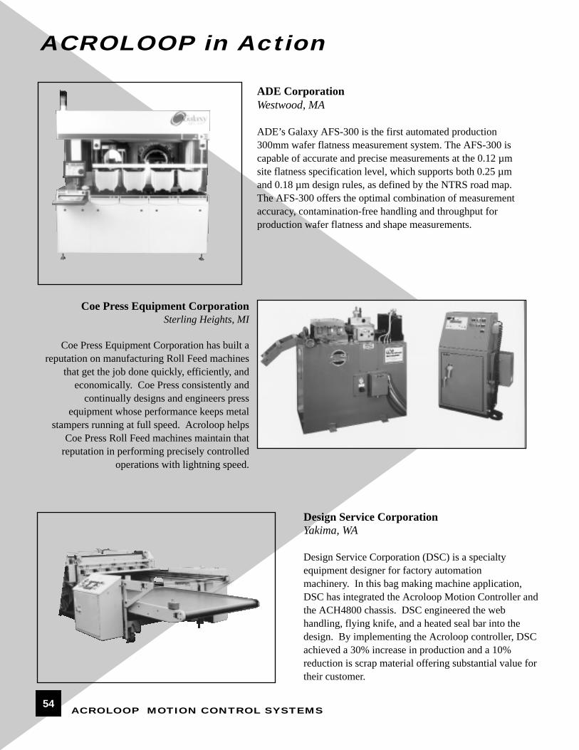
ADE Corporation Westwood, MA
ADE’s Galaxy AFS-300 is the first automated production300mm wafer flatness measurement system. The AFS-300 iscapable of accurate and precise measurements at the 0.12 µmsite flatness specification level, which supports both 0.25 µmand 0.18 µm design rules, as defined by the NTRS road map.The AFS-300 offers the optimal combination of measurementaccuracy, contamination-free handling and throughput for production wafer flatness and shape measurements.
Coe Press Equipment CorporationSterling Heights, MI
Coe Press Equipment Corporation has built areputation on manufacturing Roll Feed machines
that get the job done quickly, efficiently, and economically. Coe Press consistently and
continually designs and engineers press equipment whose performance keeps metal
stampers running at full speed. Acroloop helpsCoe Press Roll Feed machines maintain that
reputation in performing precisely controlledoperations with lightning speed.
Design Service CorporationYakima, WA
Design Service Corporation (DSC) is a specialty equipment designer for factory automation machinery. In this bag making machine application,DSC has integrated the Acroloop Motion Controller andthe ACH4800 chassis. DSC engineered the webhandling, flying knife, and a heated seal bar into thedesign. By implementing the Acroloop controller, DSCachieved a 30% increase in production and a 10%reduction is scrap material offering substantial value fortheir customer.