+ All Categories
Home > Documents > 2008 RANGER RZR SERVICE MANUAL - tradebit - Sell Files · PDF filePOLARIS ACKNOWLEDGES THE...

2008 RANGER RZR SERVICE MANUAL - tradebit - Sell Files · PDF filePOLARIS ACKNOWLEDGES THE...

Date post: 22-Mar-2018
Category:
Upload: hoangkhue
View: 224 times
Download: 2 times
Share this document with a friend
20
2008 RANGER RZR SERVICE MANUAL FOREWORD This service manual is designed primarily for use by certified Polaris Master Service Dealer technicians in a properly equipped shop and should be kept available for reference. All references to left and right side of the vehicle are from the operator's perspective when seated in a normal riding position. Some procedures outlined in this manual require a sound knowledge of mechanical theory, tool use, and shop procedures in order to perform the work safely and correctly. Technicians should read the text and be familiar with service procedures before starting the work. Certain procedures require the use of special tools. Use only the proper tools as specified. Comments or suggestions about this manual may be directed to: Service Publications Dept. @ Polaris Sales Inc. 2100 Hwy 55 Medina Minnesota 55340. 2008 Service Manual PN 9921278 © Copyright 2007 Polaris Sales Inc. All information contained within this publication is based on the latest product information at the time of publication. Due to constant improvements in the design and quality of production components, some minor discrepancies may result between the actual vehicle and the information presented in this publication. Depictions and/or procedures in this publication are intended for reference use only. No liability can be accepted for omissions or inaccuracies. Any reprinting or reuse of the depictions and/or procedures contained within, whether whole or in part, is expressly prohibited. Printed in U.S.A.
Transcript

2008 RANGER RZRSERVICE MANUAL

FOREWORD

This service manual is designed primarily for use by certified Polaris Master Service Dealer technicians in a properlyequipped shop and should be kept available for reference. All references to left and right side of the vehicle are fromthe operator's perspective when seated in a normal riding position.

Some procedures outlined in this manual require a sound knowledge of mechanical theory, tool use, and shopprocedures in order to perform the work safely and correctly. Technicians should read the text and be familiar withservice procedures before starting the work. Certain procedures require the use of special tools. Use only the propertools as specified.

Comments or suggestions about this manual may be directed to: Service Publications Dept. @ Polaris Sales Inc.2100 Hwy 55 Medina Minnesota 55340.

2008 Service Manual PN 9921278

© Copyright 2007 Polaris Sales Inc. All information contained within this publication is based on the latest product information at the time of publication. Due to constantimprovements in the design and quality of production components, some minor discrepancies may result between the actual vehicle and the information presented in thispublication. Depictions and/or procedures in this publication are intended for reference use only. No liability can be accepted for omissions or inaccuracies. Anyreprinting or reuse of the depictions and/or procedures contained within, whether whole or in part, is expressly prohibited. Printed in U.S.A.

UNDERSTANDING MANUAL SAFETY LABELS AND DIRECTIONSThroughout this manual, important information is brought to your attention by the following symbols:

SAFETY ALERT WARNING indicates a potential hazard that may result in severe injury or death to the operator, bystander orperson(s) inspecting or servicing the vehicle.

SAFETY ALERT CAUTION indicates a potential hazard that may result in minor personal injury or damage to the vehicle.

CAUTION indicates special precautions that must be taken to avoid vehicle damage or property damage.

NOTE:

NOTE provides key information by clarifying instructions.

IMPORTANT:

IMPORTANT provides key reminders during disassembly, assembly and inspection of components.

TRADEMARKSPOLARIS ACKNOWLEDGES THE FOLLOWING PRODUCTS MENTIONED IN THIS MANUAL:

Loctite, Registered Trademark of the Loctite Corporation

Nyogel, Trademark of Wm. F. Nye Co.

Fluke, Registered Trademark of John Fluke Mfg. Co.

Mity-Vac, Registered Trademark of Neward Enterprises, Inc.

Torx, Registered Trademark of Textron

Hilliard, Trademark of the Hilliard Corporation

Warn, Trademark of Warn Industries

FOX, Registered Trademark of FOX RACING SHOX

RydeFX, Registered Trademark of ArvinMeritor

Some Polaris factory publications can be downloaded from www.polarisindustires.com, purchased from www.purepolaris.com orby contacting the nearest Polaris dealer.

WARNING

CAUTION

CAUTION

1GENERAL INFORMATION

2MAINTENANCE

3ENGINE

4FUEL INJECTION

5BODY / STEERING / SUSPENSION

6CLUTCHING

7FINAL DRIVE

8TRANSMISSION

BRAKES 9

ELECTRICAL 10

GENERAL INFORMATION

CHAPTER 1GENERAL INFORMATION 1

MODEL INFORMATION . . . . . . . . . . . . . . . . . . . . . . . . . . . . . . . . . . . . . . . . . . . . . . . . . . 1.2MODEL IDENTIFICATION . . . . . . . . . . . . . . . . . . . . . . . . . . . . . . . . . . . . . . . . . . . . . . . . 1.2ENGINE DESIGNATION NUMBER . . . . . . . . . . . . . . . . . . . . . . . . . . . . . . . . . . . . . . . . . 1.2VIN IDENTIFICATION . . . . . . . . . . . . . . . . . . . . . . . . . . . . . . . . . . . . . . . . . . . . . . . . . . . 1.2ENGINE SERIAL NUMBER LOCATION . . . . . . . . . . . . . . . . . . . . . . . . . . . . . . . . . . . . . 1.2UNIT SERIAL NUMBER (VIN) LOCATION . . . . . . . . . . . . . . . . . . . . . . . . . . . . . . . . . . . 1.3

GENERAL SPECIFICATIONS. . . . . . . . . . . . . . . . . . . . . . . . . . . . . . . . . . . . . . . . . . . . . . 1.4MODEL: 2008 RANGER RZR . . . . . . . . . . . . . . . . . . . . . . . . . . . . . . . . . . . . . . . . . . . . . 1.5

VEHICLE INFORMATION . . . . . . . . . . . . . . . . . . . . . . . . . . . . . . . . . . . . . . . . . . . . . . . . . 1.6PUBLICATION NUMBERS. . . . . . . . . . . . . . . . . . . . . . . . . . . . . . . . . . . . . . . . . . . . . . . . 1.6PAINT CODES . . . . . . . . . . . . . . . . . . . . . . . . . . . . . . . . . . . . . . . . . . . . . . . . . . . . . . . . . 1.6REPLACEMENT KEYS . . . . . . . . . . . . . . . . . . . . . . . . . . . . . . . . . . . . . . . . . . . . . . . . . . 1.6

SPECIAL TOOLS . . . . . . . . . . . . . . . . . . . . . . . . . . . . . . . . . . . . . . . . . . . . . . . . . . . . . . . 1.6MISC. SPECIFICATIONS AND CHARTS . . . . . . . . . . . . . . . . . . . . . . . . . . . . . . . . . . . . . 1.7

CONVERSION TABLE . . . . . . . . . . . . . . . . . . . . . . . . . . . . . . . . . . . . . . . . . . . . . . . . . . . 1.7STANDARD TORQUE SPECIFICATIONS. . . . . . . . . . . . . . . . . . . . . . . . . . . . . . . . . . . . 1.8SAE TAP / DRILL SIZES . . . . . . . . . . . . . . . . . . . . . . . . . . . . . . . . . . . . . . . . . . . . . . . . . 1.9METRIC TAP / DRILL SIZES . . . . . . . . . . . . . . . . . . . . . . . . . . . . . . . . . . . . . . . . . . . . . . 1.9DECIMAL EQUIVALENTS . . . . . . . . . . . . . . . . . . . . . . . . . . . . . . . . . . . . . . . . . . . . . . . . 1.9GLOSSARY OF TERMS. . . . . . . . . . . . . . . . . . . . . . . . . . . . . . . . . . . . . . . . . . . . . . . . . 1.10

1.1

GENERAL INFORMATION

MODEL INFORMATION

Model IdentificationThe machine model number must be used with any correspondence regarding warranty or service.

Engine Designation NumberEH076OLE021 .....................................................Twin Cylinder, Liquid Cooled, OHV 4 Stroke, Electric Start

VIN Identification

Engine Serial Number LocationWhenever corresponding about an engine, be sure to refer to the engine model number and serial number. This information can befound on the sticker applied to the cylinder head on the side of engine.

}

Machine Model Number Identification} }

Model Year Designation

Basic Chassis Designation Engine Designation

Emissions & Model Option

R 0 8 V H 7 6 A D}

4 X A V H 7 6 A * 8 P 0 0 0 0 0 0 }

1 2 3 4 5 6 7 8 9 10 11 12 13 14 15 16 17

World Mfg. ID

Engine

Vehicle Description Vehicle Identifier }Check Digit

ModelYear Body Style

Plant No.

Individual Serial No.

* This could be either a number or a letterPowertrain

Emissions

1.2

GENERAL INFORMATION

1

Unit Serial Number (VIN) LocationThe machine model number and serial number (VIN) are important for vehicle identification. The VIN number (A) is stamped ona portion of the LH frame rail close to the front wheel. The model and VIN numbers are also located on a sticker under the hood(B) or on the lower frame rail in front of the LH rear tire (C).

A

A

B

C

1.3

GENERAL INFORMATION

GENERAL SPECIFICATIONSMODEL: 2008 RANGER RZRMODEL NUMBER: R08VH76AD, AGENGINE MODEL: EH076OLE021

Category Dimension / CapacityLength 102 in. / 259 cmWidth 50 in. / 127 cmHeight 68.5 in. / 174 cmWheel Base 77 in. / 196 cmGround Clearance 10 in. / 25.4 cmDry Weight 945 lbs. / 429 kgGross Vehicle Weight 1727 lbs. / 783 kgFront Storage Capacity 25 lbs. / 11.3 kgCargo Box Dimension 42 in. x 22 in. / 107 cm x 56 cmCargo Box Capacity 300 lbs. / 136 kg

Maximum Weight Capacity (Payload)

740 lbs. / 336.4 kg(Includes rider(s), cargo,

and accessories)Hitch Towing Capacity 1500 lbs. / 680 kgHitch Tongue Capacity 150 lbs. / 68 kg

FRONT

REAR

TOP

SIDE

1.4

GENERAL INFORMATION

1

MODEL: 2008 RANGER RZRMODEL NUMBER: R08VH76AD, AGENGINE MODEL: EH076OLE021

CLUTCH CHART

Engine

Platform Polaris Domestic Twin Cylinder, Liquid Cooled, 4-Stroke

Engine Model Number EH076OLE021Engine Displacement 760ccNumber of Cylinders 2Bore & Stroke (mm) 80 x 76.5 mmCompression Ratio 10:1

Compression Pressure 150-200 psiEngine Idle Speed 1150 ± 100 RPM

Engine Max Operating RPM 6500 ± 200 RPMLubrication Pressurized Wet Sump

Oil Requirements 0W-40Oil Capacity 2 qts. / 1.9 liters

Coolant Capacity 4.8 qts. / 4.5 litersOverheat Warning Instrument Cluster IndicatorExhaust System Single Pipe / Silencer

Fuel SystemFuel System Type Bosch Electronic Fuel Injection

Fuel Delivery Electronic Fuel Pump (in tank)Fuel Pressure 39 psiFuel Filters See Chapter 4

Fuel Capacity / Requirement 7 gal. (26.5 liters)87 Octane (minimum)

ElectricalAlternator Max Output 500 watts @ 3000 RPM

Lights: Main Headlights 2 - Dual Beam 55 watts / HalogenTail / Brake 2 - 27 wattsWorklights 2 - 13 watts

Starting System Electric StartIgnition System Bosch EFI (ECU Controlled)Ignition Timing 13° BTDC @ 1200 RPM

Spark plug / Gap Champion RC7YC3 / .035 in. (0.9 mm)

Battery Yuasa YTX20HL /18 Amp Hr. / 310 CCA / 12 Volt

Instrument Type Analog Speedometerwith Multifunction LCD

DC Outlet Standard 12 V

Relays EFI / Fan

Circuit Breaker Fan Motor: 20 Amp

Fuses

Chassis: 20 AmpEFI: 15 Amp

Lights: 15 AmpAccessory: 15 Amp

Speedo/ECU: 5 Amp

DrivetrainTransmission Type Polaris Automatic PVT

Gear Ratio: Front / RearHighLowRev

3.14:18.71:15.94:1

Drive Ratio - Front 3.82:1Drive Ratio - Final 3.70:1

Shift Type In Line Shift - H / L / N / R / P

Front Gearcase Oil RequirementsPolaris Demand Drive LT

Premium Fluid 6.75 oz. (200 ml)

Transmission Oil Requirements Main Gearcase

Polaris High Performance AGL24 oz. (710 ml)

Transmission Oil Requirements Transfer Case

Polaris High Performance AGL14 oz. (414 ml)

Rear Gearcase Oil Requirements Polaris Premium ADF18 oz. (532 ml)

Belt 3211113Steering / Suspension

Front Suspension Independent Double A-armFront Travel 9 in. / 23 cm

Rear Suspension Independent Double A-armRear Travel 9.5 in. / 24 cm

Shock Preload AdjustmentFront / Rear Cam Adjustment

Toe Out 1/8-1/4 in. / 3-6.35 mmWheels / Brakes

Front Wheel SizeFront Tire Size

12 x 6 / 10 gaugeMaxxis / 25 x 8 R12

Rear Wheel SizeRear Tire Size

12 x 8 / 10 gaugeMaxxis / 25 x 10 R12

Tire Air Pressure - Front / Rear 8 psi (55 kPa)

Brake - Front / Rear Foot Actuated - 4 Wheel Hydraulic Disc

Brake Fluid DOT 4

Altitude Shift Weight Drive Spring Driven Spring

Meters(Feet)

0-1500(0-5000)

20-62(5631700)

Blue/Red(7043199)

Red or Yellow(3234452)

1500-3700(5000 - 12000)

20-58(5631216)

Blue/Red(7043199)

Red or Yellow(3234452)

1.5

GENERAL INFORMATION

VEHICLE INFORMATION

Publication Numbers

NOTE: When ordering service parts be sure to use the correct parts manual.

NOTE: Polaris factory publications can be found at www.polarisindustries.com or purchased fromwww.purepolaris.com.

Paint Codes

Replacement KeysReplacement keys can be made from the original key. To identify which series the key is, take the first two digits on the originalkey and refer to the chart to the right for the proper part number.

SPECIAL TOOLSSpecial tools may be required while servicing this vehicle. Some of the tools listed or depicted are mandatory, while other toolsmaybe substituted with a similar tool, if available. Polaris recommends the use of Polaris Special Tools when servicing any Polarisproduct. Dealers may order special tools through Polaris’ official tool supplier, SPX Corporation, by phone at 1-800-328-6657 oron-line at http://polaris.spx.com/.

Model Model No. Owner’s Manual PN Parts Manual PN

2008 RANGER RZR, Red R08VH76AD 9921181 9921207

2008 RANGER RZR, Green R08VH76AG 9921181 9921207

Painted Part Color Description Polaris Number

Frame / Bumpers / Racks Gloss Black P-067

Frame / Bumpers / Racks Matte Black P-458

Plastic - Hood / Dash / Fenders Indy Red P-293

Plastic - Hood / Dash / Fenders Sage Brush Green Metallic P-498

Series# Part Number20 401027821 401027822 401032123 401032127 401032128 401032131 411014132 411014867 401027868 4010278

Key SeriesNumber

KEY COVERP/N 5533534

1.6

GENERAL INFORMATION

1

MISC. SPECIFICATIONS AND CHARTSConversion Table

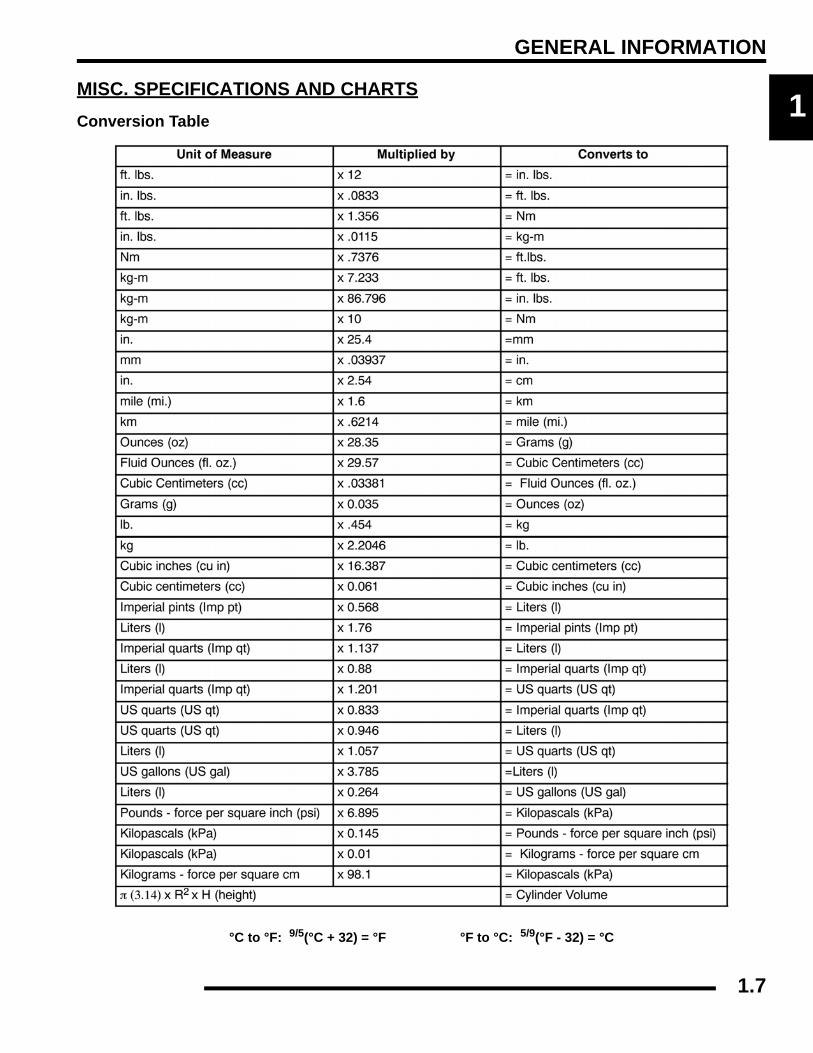
°C to °F: 9/5(°C + 32) = °F °F to °C: 5/9(°F - 32) = °C

1.7

GENERAL INFORMATION

Standard Torque Specifications

The following torque specifications are to be used only as a general guideline. There are exceptions in the steering, suspension, andengine areas. Always consult the exploded views or each manual section for torque values of fasteners before using standard torque.

1.8

GENERAL INFORMATION

1

SAE Tap / Drill Sizes

Metric Tap / Drill Sizes

Decimal Equivalents

1.9

GENERAL INFORMATION

Glossary of TermsABDC: After bottom dead center.ACV: Alternating current voltage.Alternator: Electrical generator producing voltage alternating current.ATDC: After top dead center.BBDC: Before bottom dead center.BDC: Bottom dead center.BTDC: Before top dead center.CC: Cubic centimeters.Center Distance: Distance between center of crankshaft and center of driven clutch shaft.Chain Pitch: Distance between chain link pins (No. 35 = 3/8" or 1 cm). Polaris measures chain length in number of pitches.CI: Cubic inches.Clutch Buttons: Plastic bushings which aid rotation of the movable sheave in the drive and driven clutch.Clutch Offset: Drive and driven clutches are offset so that drive belt will stay nearly straight as it moves along the clutch face.Clutch Weights: Three levers in the drive clutch which relative to their weight, profile and engine RPM cause the drive clutch toclose and grip the drive belt.Crankshaft Run-Out: Run-out or "bend" of crankshaft measured with a dial indicator while crankshaft is supported between centerson V blocks or resting in crankcase. Measure at various points especially at PTO.DCV: Direct current voltageCVT: Centrifugal Variable Transmission (Drive Clutch System)DCV: Direct current voltage.Dial Bore Gauge: A cylinder measuring instrument which uses a dial indicator. Good for showing taper and out-of-round in thecylinder bore.Electrical Open: Open circuit. An electrical circuit which isn't complete.Electrical Short: Short circuit. An electrical circuit which is completed before the current reaches the intended load. (i.e. a bare wiretouching the chassis).End Seals: Rubber seals at each end of the crankshaft.Engagement RPM: Engine RPM at which the drive clutch engages to make contact with the drive belt.ft.: Foot/feet.Foot Pound: Ft. lb. A force of one pound at the end of a lever one foot in length, applied in a rotational direction.g: Gram. Unit of weight in the metric system.gal.: Gallon.ID: Inside diameter.in.: Inch/inches.Inch Pound: In. lb. 12 in. lbs. = 1 ft. lb.kg/cm²: Kilograms per square centimeter.kg-m: Kilogram meters.Kilogram/meter: A force of one kilogram at the end of a lever one meter in length, applied in a rotational direction.l or ltr: Liter.lbs/in²: Pounds per square inch.Left or Right Side: Always referred to based on normal operating position of the driver.m: Meter/meters.Mag: Magneto.Magnetic Induction: As a conductor (coil) is moved through a magnetic field, a voltage will be generated in the windings.Mechanical energy is converted to electrical energy in the stator.mi.: Mile/miles.mm: Millimeter. Unit of length in the metric system. 1 mm = approximately .040".Nm: Newton meters.OD: Outside diameter.Ohm: The unit of electrical resistance opposing current flow.oz.: Ounce/ounces.Piston Clearance: Total distance between piston and cylinder wall.psi.: Pounds per square inch.PTO: Power take off.PVT: Polaris Variable Transmission (Drive Clutch system)qt.: Quart/quarts.Regulator: Voltage regulator. Regulates battery charging system output at approx. 14.5 DCV as engine RPM increases.Reservoir Tank: The fill tank in the liquid cooling system.Resistance: In the mechanical sense, friction or load. In the electrical sense, ohms, resulting in energy conversion to heat.RPM: Revolutions per minute.Seized Piston: Galling of the sides of a piston. Usually there is a transfer of aluminum from the piston onto the cylinder wall.Possible causes: 1) improper lubrication; 2) excessive temperatures; 3) insufficient piston clearance; 4) stuck piston rings.Stator Plate: The plate mounted under the flywheel supporting the battery charging coils.TDC: Top dead center. Piston's most outward travel from crankshaft.Volt: The unit of measure for electrical pressure of electromotive force. Measured by a voltmeter in parallel with the circuit.Watt: Unit of electrical power. Watts = amperes x volts.WOT: Wide open throttle.

1.10

MAINTENANCE

CHAPTER 2MAINTENANCE

2

PERIODIC MAINTENANCE CHART. . . . . . . . . . . . . . . . . . . . . . . . . . . . . . . . . . . . . . . . . 2.3PERIODIC MAINTENANCE OVERVIEW. . . . . . . . . . . . . . . . . . . . . . . . . . . . . . . . . . . . . 2.3BREAK-IN PERIOD . . . . . . . . . . . . . . . . . . . . . . . . . . . . . . . . . . . . . . . . . . . . . . . . . . . . . 2.3MAINTENANCE CHART KEY . . . . . . . . . . . . . . . . . . . . . . . . . . . . . . . . . . . . . . . . . . . . . 2.3PRE-RIDE - 25 HOUR MAINTENANCE INTERVAL . . . . . . . . . . . . . . . . . . . . . . . . . . . . 2.450 - 300 HOUR MAINTENANCE INTERVAL . . . . . . . . . . . . . . . . . . . . . . . . . . . . . . . . . . 2.5

COMPONENT INSPECTION / SERVICE LOCATIONS . . . . . . . . . . . . . . . . . . . . . . . . . . 2.6FRONT AND REAR VIEW . . . . . . . . . . . . . . . . . . . . . . . . . . . . . . . . . . . . . . . . . . . . . . . . 2.6RH AND LH SIDE VIEWS. . . . . . . . . . . . . . . . . . . . . . . . . . . . . . . . . . . . . . . . . . . . . . . . . 2.7

LUBRICANTS / SERVICE PRODUCTS . . . . . . . . . . . . . . . . . . . . . . . . . . . . . . . . . . . . . . 2.8POLARIS LUBRICANTS, MAINTENANCE AND SERVICE PRODUCTS . . . . . . . . . . . . 2.8

MAINTENANCE REFERENCES . . . . . . . . . . . . . . . . . . . . . . . . . . . . . . . . . . . . . . . . . . . . 2.9GENERAL VEHICLE INSPECTION AND MAINTENANCE. . . . . . . . . . . . . . . . . . . . . . . 2.10

PRE-RIDE / DAILY INSPECTION . . . . . . . . . . . . . . . . . . . . . . . . . . . . . . . . . . . . . . . . . 2.10FRAME, NUTS, BOLTS, AND FASTENERS . . . . . . . . . . . . . . . . . . . . . . . . . . . . . . . . . 2.10SHIFT CABLE INSPECTION / ADJUSTMENT. . . . . . . . . . . . . . . . . . . . . . . . . . . . . . . . 2.10

FUEL SYSTEM AND AIR INTAKE . . . . . . . . . . . . . . . . . . . . . . . . . . . . . . . . . . . . . . . . . 2.11FUEL SYSTEM. . . . . . . . . . . . . . . . . . . . . . . . . . . . . . . . . . . . . . . . . . . . . . . . . . . . . . . . 2.11FUEL LINE . . . . . . . . . . . . . . . . . . . . . . . . . . . . . . . . . . . . . . . . . . . . . . . . . . . . . . . . . . . 2.11FUEL PUMP / FUEL FILTERS . . . . . . . . . . . . . . . . . . . . . . . . . . . . . . . . . . . . . . . . . . . . 2.11VENT LINES. . . . . . . . . . . . . . . . . . . . . . . . . . . . . . . . . . . . . . . . . . . . . . . . . . . . . . . . . . 2.11THROTTLE PEDAL INSPECTION . . . . . . . . . . . . . . . . . . . . . . . . . . . . . . . . . . . . . . . . . 2.12THROTTLE FREEPLAY ADJUSTMENT . . . . . . . . . . . . . . . . . . . . . . . . . . . . . . . . . . . . 2.12AIR FILTER SERVICE . . . . . . . . . . . . . . . . . . . . . . . . . . . . . . . . . . . . . . . . . . . . . . . . . . 2.12

ENGINE . . . . . . . . . . . . . . . . . . . . . . . . . . . . . . . . . . . . . . . . . . . . . . . . . . . . . . . . . . . . . . 2.14ENGINE OIL LEVEL . . . . . . . . . . . . . . . . . . . . . . . . . . . . . . . . . . . . . . . . . . . . . . . . . . . . 2.14ENGINE OIL AND FILTER SERVICE. . . . . . . . . . . . . . . . . . . . . . . . . . . . . . . . . . . . . . . 2.15ENGINE BREATHER HOSE INSPECTION . . . . . . . . . . . . . . . . . . . . . . . . . . . . . . . . . . 2.16ENGINE AND TRANSMISSION MOUNT LOCATIONS . . . . . . . . . . . . . . . . . . . . . . . . . 2.16COMPRESSION AND LEAKDOWN TEST. . . . . . . . . . . . . . . . . . . . . . . . . . . . . . . . . . . 2.16EXHAUST - SPARK ARRESTOR. . . . . . . . . . . . . . . . . . . . . . . . . . . . . . . . . . . . . . . . . . 2.16

TRANSMISSION AND GEARCASES . . . . . . . . . . . . . . . . . . . . . . . . . . . . . . . . . . . . . . . 2.17TRANSMISSION / GEARCASE SPECIFICATION CHART . . . . . . . . . . . . . . . . . . . . . . 2.17TRANSMISSION LUBRICATION . . . . . . . . . . . . . . . . . . . . . . . . . . . . . . . . . . . . . . . . . 2.17FRONT GEARCASE LUBRICATION . . . . . . . . . . . . . . . . . . . . . . . . . . . . . . . . . . . . . . . 2.19REAR GEARCASE LUBRICATION . . . . . . . . . . . . . . . . . . . . . . . . . . . . . . . . . . . . . . . . 2.20

COOLING SYSTEM. . . . . . . . . . . . . . . . . . . . . . . . . . . . . . . . . . . . . . . . . . . . . . . . . . . . . 2.21COOLING SYSTEM OVERVIEW . . . . . . . . . . . . . . . . . . . . . . . . . . . . . . . . . . . . . . . . . . 2.21COOLANT LEVEL INSPECTION . . . . . . . . . . . . . . . . . . . . . . . . . . . . . . . . . . . . . . . . . . 2.21COOLANT STRENGTH / TYPE . . . . . . . . . . . . . . . . . . . . . . . . . . . . . . . . . . . . . . . . . . . 2.21COOLING SYSTEM PRESSURE TEST. . . . . . . . . . . . . . . . . . . . . . . . . . . . . . . . . . . . . 2.22COOLING SYSTEM HOSES . . . . . . . . . . . . . . . . . . . . . . . . . . . . . . . . . . . . . . . . . . . . . 2.22RADIATOR . . . . . . . . . . . . . . . . . . . . . . . . . . . . . . . . . . . . . . . . . . . . . . . . . . . . . . . . . . . 2.22COOLANT DRAIN / RADIATOR REMOVAL . . . . . . . . . . . . . . . . . . . . . . . . . . . . . . . . . 2.22

FINAL DRIVE / WHEEL AND TIRE . . . . . . . . . . . . . . . . . . . . . . . . . . . . . . . . . . . . . . . . . 2.23WHEEL, HUB, AND SPINDLE TORQUE TABLE. . . . . . . . . . . . . . . . . . . . . . . . . . . . . . 2.23WHEEL REMOVAL. . . . . . . . . . . . . . . . . . . . . . . . . . . . . . . . . . . . . . . . . . . . . . . . . . . . . 2.23WHEEL INSTALLATION. . . . . . . . . . . . . . . . . . . . . . . . . . . . . . . . . . . . . . . . . . . . . . . . . 2.23TIRE INSPECTION. . . . . . . . . . . . . . . . . . . . . . . . . . . . . . . . . . . . . . . . . . . . . . . . . . . . . 2.24TIRE PRESSURE. . . . . . . . . . . . . . . . . . . . . . . . . . . . . . . . . . . . . . . . . . . . . . . . . . . . . . 2.24DRIVE SHAFT BOOT INSPECTION . . . . . . . . . . . . . . . . . . . . . . . . . . . . . . . . . . . . . . . 2.24

2.1

MAINTENANCE

ELECTRICAL AND IGNITION SYSTEM . . . . . . . . . . . . . . . . . . . . . . . . . . . . . . . . . . . . . 2.25BATTERY MAINTENANCE . . . . . . . . . . . . . . . . . . . . . . . . . . . . . . . . . . . . . . . . . . . . . . 2.25BATTERY REMOVAL. . . . . . . . . . . . . . . . . . . . . . . . . . . . . . . . . . . . . . . . . . . . . . . . . . . 2.25BATTERY INSTALLATION. . . . . . . . . . . . . . . . . . . . . . . . . . . . . . . . . . . . . . . . . . . . . . . 2.25BATTERY OFF SEASON STORAGE . . . . . . . . . . . . . . . . . . . . . . . . . . . . . . . . . . . . . . 2.26BATTERY CHARGING (SEALED BATTERY) . . . . . . . . . . . . . . . . . . . . . . . . . . . . . . . . 2.26SPARK PLUG SERVICE . . . . . . . . . . . . . . . . . . . . . . . . . . . . . . . . . . . . . . . . . . . . . . . . 2.26ENGINE TO FRAME GROUND . . . . . . . . . . . . . . . . . . . . . . . . . . . . . . . . . . . . . . . . . . . 2.27

STEERING AND SUSPENSION . . . . . . . . . . . . . . . . . . . . . . . . . . . . . . . . . . . . . . . . . . . 2.27STEERING INSPECTION . . . . . . . . . . . . . . . . . . . . . . . . . . . . . . . . . . . . . . . . . . . . . . . 2.27STEERING WHEEL FREEPLAY . . . . . . . . . . . . . . . . . . . . . . . . . . . . . . . . . . . . . . . . . . 2.27STEERING INSPECTION / TIE ROD ENDS AND HUBS . . . . . . . . . . . . . . . . . . . . . . . 2.28TOE ALIGNMENT INSPECTION . . . . . . . . . . . . . . . . . . . . . . . . . . . . . . . . . . . . . . . . . . 2.28TOE ADJUSTMENT . . . . . . . . . . . . . . . . . . . . . . . . . . . . . . . . . . . . . . . . . . . . . . . . . . . . 2.29SUSPENSION SPRING PRELOAD ADJUSTMENT . . . . . . . . . . . . . . . . . . . . . . . . . . . 2.29

BRAKE SYSTEM. . . . . . . . . . . . . . . . . . . . . . . . . . . . . . . . . . . . . . . . . . . . . . . . . . . . . . . 2.30BRAKE FLUID INSPECTION . . . . . . . . . . . . . . . . . . . . . . . . . . . . . . . . . . . . . . . . . . . . . 2.30BRAKE PAD / DISC INSPECTION. . . . . . . . . . . . . . . . . . . . . . . . . . . . . . . . . . . . . . . . . 2.30BRAKE HOSE AND FITTING INSPECTION . . . . . . . . . . . . . . . . . . . . . . . . . . . . . . . . . 2.30

2.2

MAINTENANCE

2

PERIODIC MAINTENANCE CHARTPeriodic Maintenance OverviewInspection, adjustment and lubrication of important components are explained in the periodic maintenance chart.

Inspect, clean, lubricate, adjust and replace parts as necessary. When inspection reveals the need for replacement parts, usegenuine Pure Polaris parts available from your Polaris dealer.

NOTE: Service and adjustments are critical. If you’re not familiar with safe service and adjustmentprocedures, have a qualified dealer perform these operations.

Maintenance intervals in the following chart are based upon average riding conditions and an average vehicle speed of approximately10 miles per hour. Vehicles subjected to severe use must be inspected and serviced more frequently.

Severe Use Definition

• Frequent immersion in mud, water or sand

• Racing or race-style high RPM use

• Prolonged low speed, heavy load operation

• Extended idle

• Short trip cold weather operation

Pay special attention to the oil level. A rise in oil level during cold weather can indicate contaminants collecting in the oil sump orcrankcase. Change oil immediately if the oil level begins to rise. Monitor the oil level, and if it continues to rise, discontinue useand determine the cause or see your dealer.

Break-In PeriodThe break-in period consists of the first 25 hours of operation, or the time it takes to use 14 gallons (53 liters) of fuel. Careful treatmentof a new engine and drive components will result in more efficient performance and longer life for these components.

• Drive vehicle slowly at first while varying the throttle position. Do not operate at sustained idle.

• Pull only light loads.

• Perform regular checks on fluid levels and other areas outlined on the daily pre-ride inspection checklist.

• Change both the engine oil and filter after 25 hours or one month.

• See “Owner’s Manual” for additional break-in information.

Maintenance Chart KeyThe following symbols denote potential items to be aware of during maintenance:

= CAUTION: Due to the nature of these adjustments, it is recommended this service be performed by anauthorized Polaris dealer.

= SEVERE USE ITEM: See information provided above.

E = Emission Control System Service (California).

NOTE: Inspection may reveal the need for replacement parts. Always use genuine Polaris parts.

WARNING

Improperly performing the procedures marked could result in component failure and lead to serious injury or death.Have an authorized Polaris dealer perform these services.

2.3

MAINTENANCE

Pre-Ride - 25 Hour Maintenance Interval

Perform these procedures more often for vehicles subjected to severe use. E Emission Control System Service (California)

Have an authorized Polaris dealer perform these services.

Item

Maintenance Interval(whichever comes first)

RemarksHours Calendar Miles

(KM)Steering - Pre-Ride -

Make adjustments as needed. See Pre-Ride Checklist on Page 2.9.

Front Suspension - Pre-Ride -Rear Suspension - Pre-Ride -Tires - Pre-Ride -Brake Fluid Level - Pre-Ride -Brake Pedal Travel - Pre-Ride -Brake Systems - Pre-Ride -Wheels / Fasteners - Pre-Ride -Frame Fasteners - Pre-Ride -

EEngine Oil Level - Pre-Ride -

EAir Filter / Pre-Filter - Pre-Ride - Inspect; clean often; replace as needed

Coolant Level - Daily - Check level daily, change coolant every 2 years

Head Lamp / Tail Lamp - Daily - Check operation; apply dielectric grease if replacing

EAir Filter,Main Element - Weekly - Inspect; replace as needed

Brake Pad Wear 10 H Monthly 100 (160) Inspect periodically

Battery 25 H Monthly 250 (400) Check terminals; clean; testFront Gearcase Oil (Demand Drive Fluid LT) 25 H Monthly 250 (400) Inspect level; change yearly

Rear Gearcase Oil (ATV Angle Drive Fluid) 25 H Monthly 250 (400) Inspect level; change yearly

Transmission - Main(AGL Gearcase Lubricant) 25 H Monthly 250 (400) Inspect level; change yearly

Transmission - Transfer(AGL Gearcase Lubricant) 25 H Monthly 250 (400) Inspect level; change yearly

EEngine Breather Filter (if equipped) 25 H Monthly 250 (400) Inspect; replace if necessary

EEngine Oil Change (Break-In Period) 25 H 1 M 250 (400) Perform a break-in oil change at one month

2.4

MAINTENANCE

2

50 - 300 Hour Maintenance Interval

Perform these procedures more often for vehicles subjected to severe use. E Emission Control System Service (California)

Have an authorized Polaris dealer perform these services.

Item

Maintenance Interval (whichever comes first) Remarks

Hours Calendar Miles (KM)

EThrottle Cable / Throttle Pedal 50 H 6 M 300 (500) Inspect; adjust; lubricate; replace if

necessary

E Throttle Body Air Intake Ducts / Flange 50 H 6 M 300 (500) Inspect ducts for proper sealing / air leaks

General Lubrication 50 H 3 M 500 (800) Lubricate all fittings, pivots, cables, etc.Shift Linkage 50 H 6 M 500 (800) Inspect, lubricate, adjustSteering 50 H 6 M 500 (800) LubricateFront Suspension 50 H 6 M 500 (800) LubricateRear Suspension 50 H 6 M 500 (800) Lubricate

Cooling System 50 H 6 M 500 (800) Inspect coolant strength seasonally; pressure test system yearly

E Fuel System 100 H 12 M 600 (1000)Check for leaks at tank cap, fuel line, fuel pump, and fuel rail. Replace lines every two years.

E Spark Plug 100 H 12 M 600 (1000) Inspect; replace as needed

EEngine Oil & Filter Change 100 H 6 M 1000 (1600)

Perform a break-in oil change at 25 hours or one month / always replace oil filter when changing engine oil

Drive Belt 100 H 12 M 1000 (1600) Inspect; replace as neededRadiator 100 H 12 M 1000 (1600) Inspect; clean external surfacesCooling Hoses 100 H 12 M 1000 (1600) Inspect for leaksEngine Assembly Mounts 100 H 12 M 1000 (1600) Inspect, torque to specificationExhaust Muffler / Pipe 100 H 12 M 1000 (1600) Inspect

Wiring 100 H 12 M 1000 (1600)Inspect for wear, routing, security; apply dielectric grease to connectors subjected to water, mud, etc.

Clutches (Drive and Driven) 100 H 12 M 1000 (1600) Inspect; clean; replace worn partsFront Wheel Bearings 100 H 12 M 1000 (1600) Inspect; replace as neededBrake Fluid 200 H 24 M 2000 (3200) Change every two years (DOT 4)Spark Arrestor 300 H 36 M 3000 (4800) Clean out

Toe Adjustment - Inspect periodically; adjust when parts are replaced

Headlight Aim - Adjust as needed

2.5

MAINTENANCE

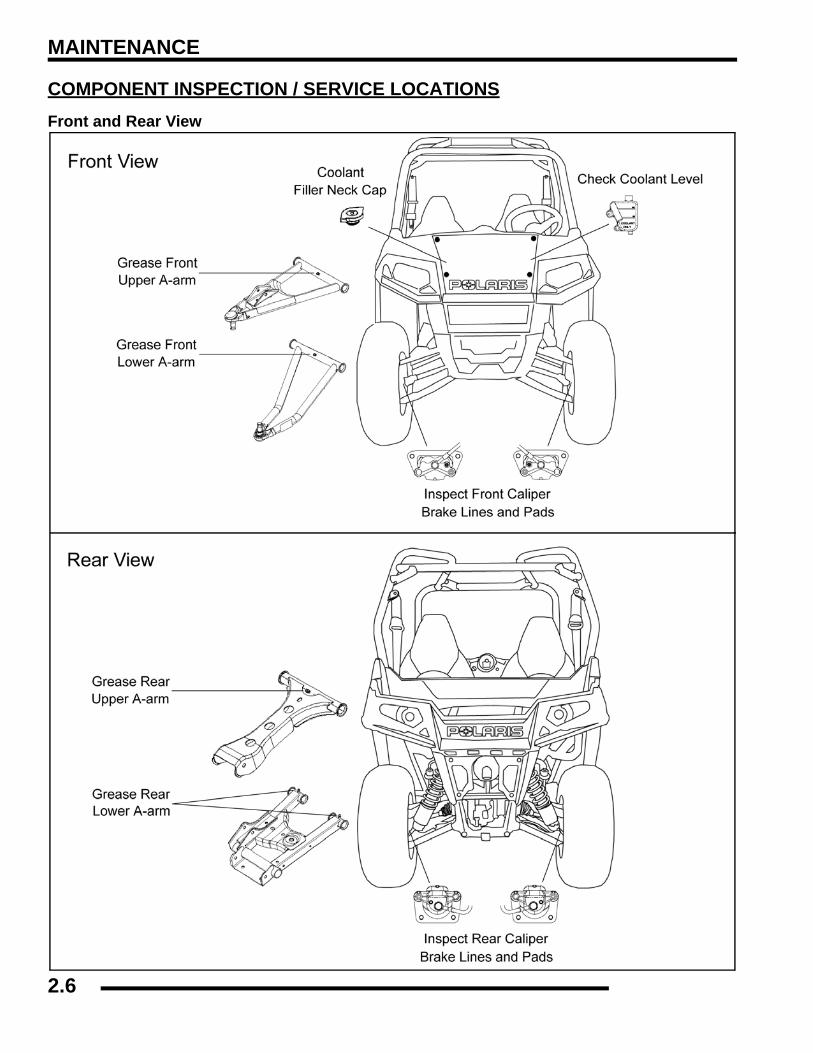
COMPONENT INSPECTION / SERVICE LOCATIONSFront and Rear View

2.6

MAINTENANCE

2

RH and LH Side Views

2.7


Recommended