54
2012+ Camaro SS H.O. & Stage II Intercooled System Installation Guide

2012+ Camaro SS H.O. & Stage II Intercooled System
Installation Guide

© 2014 Accessible Technologies, Inc.
Accessible Technologies, Inc. 14801 W. 114th Terrace
Lenexa, KS 66215 Phone: 913.338.2886
Fax: 913.338.2879 [email protected]
All rights reserved. Accessible Technologies Inc. hereby grants permission to use and reproduce this document for personal use, provided that all copyright information be retained. Reproduction of this document for unauthorized commercial use is strictly prohibited.
Information in this document is subject to change without notice.
ProCharger is a registered trademark and The Intercooled Supercharging Experts!TM and Designed to Blow Away the CompetitionTM are trademarks of Accessible Technologies, Inc. and may not be used without express permission.
Revised 5/14 Part Number PMGT1A-004 Rev. G Printed in the USA
You should also have the following gauges available to properly check the finished installation and monitor your vehicle’s performance (especially for testing):
• Manifold Boost Pressure Gauge • Fuel Pressure Gauge • Wide Band Oxygen Sensor and Gauge
Gauges should be of a type that can be read from the cockpit while performing a wide-open throttle road test. Cockpit or hood-mounted gauges are preferable. In order to obtain usable readings, the gauges should measure pressure at the intake manifold and fuel rail. IF VEHICLE DOES NOT MAINTAIN PROPER FUEL PRESSURE (50-65 PSI), DECREASE THROTTLE APPLICATION IMMEDIATELY. In some cases, extra vehicle modifications can strain the stock fuel pump. If your vehicle has difficulty retaining adequate fuel pressure, contact ATI ProCharger about the availability of an upgraded fuel system.
The engine on which the ProCharger® is to be installed should retain the factory compression ratio. If it has been modified in any way, please consult ProCharger staff before proceeding with the installation. This supercharger system is intended for use on STOCK, strong, well-maintained engines/transmissions. Installation on a worn or troublesome powertrain should be reconsidered. ATI PROCHARGER WILL NOT BE HELD RESPONSIBLE FOR DAMAGE TO A VEHICLE’S POWERTRAIN. ATI ProCharger is not responsible for ECM tuning/programming on non-stock vehicles. ATI PROCHARGER recommends verifying that your vehicle has current ECM updates from the vehicle manufacturer before installation.
For best performance and reliability, always use premium grade fuel (91 octane or higher) and listen closely for signs of detonation, which might sound like ball bearings rolling around in a tin can. IF DETONATION SHOULD OCCUR, OR IF YOU ARE UNSURE WHETHER WHAT YOU’RE HEARING IS DETONATION, DECREASE THROTTLE APPLICATION IMMEDIATELY and please consult ATI ProCharger staff. Detonation should not be an issue with a properly installed intercooled supercharger system, though OEM factory-shipped engine and parts inconsistencies are possible on any vehicle.

2012+ Camaro SS H. O. & Stage II System Installation Guide i
Introduction
Congratulations on purchasing your ProCharger® 2012+ Camaro SS High Output or Stage II Intercooled System. Read this entire manual before you attempt to install your ProCharger kit. It is imperative that you follow all of the instructions in the order they appear in this installation guide. If you have any questions regarding any aspect of this installation, call us at (913) 338-2886.
For best results, we recommend reviewing the installation instructions beforehand, and following the installation instructions closely and in sequence. A detailed packing list has been provided to assist you in identifying the components of your ProCharger system.
Tech Tip: Installing spark plugs that are one heat ranger colder than stock and gapping your plugs to .035” is recommended.
Warning: Read and understand all safety precautions in this manual before installation. Failure to comply with instructions in this manual could result in personal injury, property damage, and/or voiding your warranty.
Required Tools and Supplies• 3/8” & 1/2” Socket Sets (standard & metric) • 1/2” Impact Gun • 1/2” Breaker Bar • T20 Torx Bit • Open End Wrench Set (standard & metric) • 3/8” Hex Bit Set (standard & metric)) • Flat & Phillips Screwdrivers • Plier Set • Propane torch • Loctite 272 • Drill and 1/2” Drill Bit • GM Balancer Install Tool • GM Balancer Removal Tool
Warning: Your supercharged Camaro must always be run on 91 octane or better gas. The best way to insure this is to run the tank near empty (below 1/4) and fill with 91 octane for several tanks prior to installing the supercharger.
IntroductIon

ii 2012+ Camaro SS H. O. & Stage II System Installation Guide
Introduction
table of contents
Introduction ............................................................................................................................................................................................. i
Table of Contents .................................................................................................................................................................................. ii
Getting Started.......................................................................................................................................................................................1
Crank Pulley ...........................................................................................................................................................................................10
Main Bracket Assembly .....................................................................................................................................................................15
ProCharger Head Unit ........................................................................................................................................................................22
Intercooler and Tubing ......................................................................................................................................................................24
Windshield Washer Reservoir ..........................................................................................................................................................29
Coolant Hose .........................................................................................................................................................................................30
Tuning......................................................................................................................................................................................................31
Fuel System ............................................................................................................................................................................................32
PCV System ............................................................................................................................................................................................37
Vacuum Manifold ................................................................................................................................................................................39
Final Assembly ......................................................................................................................................................................................40
Operation and Maintenance ...........................................................................................................................................................43
Limited Warranty .................................................................................................................................................................................45
ProCharger Extended Coverage ....................................................................................................................................................46
PLEASE PROCEED TO THE TUNING SECTION FOR COMPLETE SYSTEM INSTALLATIONS. TUNING THESE VEHICLES IS A MULTI-STEP PROCESS THAT SHOULD BE INITIATED BEFORE SYSTEM INSTALLATION BEGINS. PLEASE ALLOW 24 HOURS TO RECEIVE YOUR MODIFIED TUNE FILE. CONTACT ATI WITH ANY QUESTIONS REGARDING TUNING FOR THESE VEHICLES.

2012+ Camaro SS H. O. & Stage II System Installation Guide 1
Getting Started
GettInG started
Read and understand all safety precautions in this manual before installation. Failure to comply with instructions in this manual could result in personal injury, property damage, and/or voiding your warranty.
(A) Factory Air Filter Box
(B) Mass Airflow (MAF) sensor
(C) Factory Inlet Pipe
(D) Plastic Engine Cover
Completion of this section will configure the vehicle for system installation:
A
B
C
D

2 2012+ Camaro SS H. O. & Stage II System Installation Guide
Getting Started
1 Disconnect the negative battery cable from the battery (located in the trunk) using a 10mm wrench.
2 Remove the engine cover by removing the oil cap, then pulling firmly upward and out towards the front of the vehicle. Set the cover aside.
3 Disconnect the Mass Airflow Meter (MAF) wiring harness from the intake tube by pressing the tab together and pulling out.
4 Disconnect the PCV line running to the factory intake system by firmly pulling it out. Remove the opposite end of the PCV line attached to the passenger’s side valve cover by squeezing the connector tabs together and pulling out. This will no longer be used. Using a 5/16” nut driver, loosen the throttle body hose clamp.
5 Remove the (2) nuts that fasten the air cleaner box to the vehicle using a 10mm socket.
6 Firmly pull up on the air filter box and remove the entire factory air intake system from the vehicle.
MAF Connector
Disconnect MAF Harness From Intake Tube
Remove Air Cleaner Box Fasteners
Remove (2) 10mm Nuts
Throttle Body Hose Clamp
Disconnect PCV Line and Loosen Hose Clamp
PCV Line

2012+ Camaro SS H. O. & Stage II System Installation Guide 3
Getting Started
7 Using a T20 Torx bit, remove the MAF sensor from the factory intake tube and set it aside for reuse later. The rest of the intake system will not be re-installed.
8 Remove the upper fascia fasteners with a 10mm socket (driver’s and passenger’s side).
9 Using a flat bladed screwdriver, remove the (6) push pins from the top of the vehicle.
10 Raise the front of the vehicle.
11 Remove the front wheels from the vehicle.
12 Using a T20 torx bit, remove the screws (3 per side) that attach the inner splash panel to the front fascia.
Remove Factory MAF From Intake Tube
Remove Upper Fascia Fasteners & Push Pins
Upper Fastener (2X)
Upper Push Pins (6X)
Remove Screws (3 Per Side)

4 2012+ Camaro SS H. O. & Stage II System Installation Guide
Getting Started
13 Pull back the splash panel to gain access to the remaining fasteners that connect the fascia to the vehicle. Using a 7mm socket, remove the screws (1 per side) that fasten vertically per the image on the right.
14 2014+ Model Years: From underneath, use a 7mm socket to remove the 3 screws on each side holding the bottom of the inner fender to the fascia.
15 With a 10mm socket and 3” extension, remove the screws (4 per side) that secure the fascia to the fender (located behind the front fascia). They can be accessed from the wheel well area.
16 From underneath the vehicle, remove the (2) 10mm screws (if equipped).
Remove 7mm Screw (1 Per Side)
Remove Lower Screw
10mm Screw Removal (8 Total)
Lower 10mm Screw Removal (2X)

2012+ Camaro SS H. O. & Stage II System Installation Guide 5
Getting Started
17 Pull out on each side of the fascia to unclip it from the vehicle. Pull the entire fascia forward and separate it from the vehicle. Unplug the wiring harness located on the passenger’s side. Remove the fascia from the vehicle.
18 Unclip the ambient air temperature sensor and wiring harness that is connected to the radiator shrouding.
19 Remove the (4) bolts that secure the front brace to the vehicle (convertible models only). Remove the brace from the vehicle.
20 Three (3) seperate pieces make up the radiator shrouding. Remove the plastic radiator shrouding by removing the (8) push pins holding it in place.)
Remove Radiator Shrouding
Remove Radiator Shroud
Unclip Wiring Harness and Temp. Sensor
Radiator Shrouding Removed
Remove Front Brace (Convertible Only)
Front Brace

6 2012+ Camaro SS H. O. & Stage II System Installation Guide
Getting Started
21 Using a 13mm socket and 3” extension, remove the fasteners (3 per side) that connect the front bumper to the vehicle. Remove the bumper and set it aside.
22 Place a pan under the radiator drain cock; open the drain cock by rotating the fitting counter clockwise. Removing the coolant cap from the top of the radiator will speed up this process. Once all coolant has been released, close the drain cock.
23 Using a pair of pliers, loosen the upper coolant hose clamps and remove the upper coolant hose.
24 Disconnect the (2) coolant lines that run below the radiator cap. Pull the filler neck off of the overflow tank and remove from the vehicle (this will make extra room for the fan removal).
Remove Front Bumper (Driver’s Side Fasteners)
Remove Upper Coolant Hose
Upper Radiator Hose
Filler Neck Removal
Filler Neck

2012+ Camaro SS H. O. & Stage II System Installation Guide 7
Getting Started
25 Unplug the cooling fan wiring harness located on the passenger’s side of the vehicle. Using a 13mm socket, remove the (2) screws that fasten the fan to the fan shroud. Shift the fan towards the rear of the vehicle, and lift it up and out of the vehicle. Set it aside, it will be re-installed later.
26 Locate the windshield washer reservoir on the driver’s side of the vehicle. Place a pan under the reservoir, disconnect the main line found on the side of the reservoir, and drain. Unplug the wiring harness from the reservoir. Using a 13mm socket and 3” extension, remove the (3) bolts fastening the reservoir to the vehicle. Remove the reservoir from the vehicle, it will be replaced by a new unit.
Fan Removal
Remove 13mm Screws (2X)
Unplug Wiring Harness
Windshield Washer Reservoir RemovalDisconnect Line

8 2012+ Camaro SS H. O. & Stage II System Installation Guide
Getting Started
27 2012 Models: Loosen the (2) clamps holding the lower power steering line to the vehicle. Slide the line to the driver’s side until the passenger’s side clamp stops at the 180° bend in the line. Tighten the clamps back into place. This will make room for the blower bracket installation.
28 Place a 15mm socket onto the factory tensioner bolt and rotate clockwise until there is slack in the factory accessory belt. Remove the belt from the vehicle. Release the tensioner. Lower Power Steering Line, Stock Location
Lower Power Steering Line
Slide Line Toward Driver’s Side
New Lower Power Steering Line Location
Loosen Tensioner and Remove Accessory Belt

2012+ Camaro SS H. O. & Stage II System Installation Guide 9
Getting Started
29 Locate the A/C compressor on the lower passenger’s side of the vehicle. Remove the (4) bolts fastening the compressor to the A/C bracket using a 13mm socket and extension.
30 Slide the compressor towards the front of the vehicle. You should now be able to slide the 4 rib A/C belt off of the factory balancer.
31 Remove the stud used to fasten the factory air intake system to the vehicle.
Tech Tip: H.O. systems include a new stud and speed nut for re-installation of the factory air intake system at a later time.
Remove (4) A/C Compressor Bolts
Remove Stud

10 2012+ Camaro SS H. O. & Stage II System Installation Guide
Crank Pulley
crank Pulley
Tech Tip: If installing on a manual transmission vehicle, placing the car in 6th gear with the rear wheels on the ground will eliminate the need to lock the flywheel through the access cover.
1 Identify the transmission access cover, located under the vehicle in front of the transmission. It is secured by (1) bolt. Remove this bolt with a 10mm socket, and set the cover aside.
2 Looking inside the transmission access hole, the flywheel should be visible. Using a large flathead screwdriver, place the screwdriver into one of the holes in the flywheel to keep the flywheel from spinning during the crank pulley bolt removal.
3 Remove the factory crank bolt using a 24mm socket.
Tech Tip: Using a torch to heat the flange on the crank pulley bolt makes removal easier. There is an adhesive on the back of the flange which helps retain the bolt. Heating this breaks the adhesion.
4 Use a balancer removal tool to remove the factory crank balancer.
Crank Balancer Removed

2012+ Camaro SS H. O. & Stage II System Installation Guide 11
Crank Pulley
5 Using a GM crank balancer installation tool, install the supplied modified balancer onto the crankshaft.
Tech Tip: If installing an aftermarket balancer, install it according to the manufacturer’s specs at this time (ATI Performance Products Damper part #918635).
6 To ensure that the balancer does not spin independently from the crank, the two must be pinned.
7 Following the diagram to the right, set up the drill bit, measuring 1-5/8” from the end and taping the bit for drill depth reference.
8 Place the provided bolt through the pinning fixture, and tighten onto the crankshaft with a 24mm socket.
9 Drill the crank to the proper depth, then remove the bolt and fixture. Clean the area thoroughly, including the drilled hole.
10 Place the 1/4” pin into the crank; be sure the pin is set all the way into the crank (tapping the pin with a rubber mallet is acceptable).
Balancer Pinned to Crankshaft
Crankshaft and Harmonic Balancer Drill Jig
M14-1.50 x 120MM BOLT
Drill Fixture In Place

12 2012+ Camaro SS H. O. & Stage II System Installation Guide
Crank Pulley
Installation Using Factory Balancer
11 Insert the (6) 5/16 - 18 bolts and washers through the supplied pulley, apply Loctite 272 to the bolts and thread the (6) supplied cam locks onto the threads from behind the pulley. Hand tighten the cam locks.
12 Mount the crank pulley and cam locks onto the factory balancer, ensuring (2) cam locks are inserted into each slot on the balancer.
13 Place the provided cupped washer onto the new crank bolt, insert into the new crank pulley and into the crank. Rotate the assembly until the cam locks stop the pulley. Tighten the crank bolt to 240 ft-lbs. Be sure the flathead that is holding the flywheel stationary is properly positioned for tightening.
14 Activate the cam locks by tightening the (6) bolts to ensure that the crank pulley and balancer spin together.
15 Remove the screwdriver from the transmission access hole, replace the access shield, and tighten the bolt.
16 Re-install the 4 rib A/C belt. Slide the A/C compressor back into place and tighten the (4) bolts with a 13mm socket.
17 Zip tie the (2) lines that run near the crank pulley together, and out of the way.
Tech Tip: The power steering lines may need to be slightly bent for clearance from the belt.
Crank Pulley and Cam Lock Assembly
Cam Lock Positions From Back Side View
2 CAMLOCKS PER SLOT
Zip Tie Lines Out Of Way
Crank Pulley Installed

2012+ Camaro SS H. O. & Stage II System Installation Guide 13
Crank Pulley
Installation Using ATI Performance Products Damper/8 & 12 Rib Kits
11 Insert the provided new factory crank bolt into the damper assembly and into the crank. Tighten the crank bolt to 240 ft-lbs. Be sure the flathead that is holding the flywheel stationary is properly positioned for tightening.
12 Remove the screwdriver from the transmission access hole, replace the access shield, and tighten the bolt.
13 Re-install the 4 rib A/C belt. Slide the A/C compressor back into place and tighten the (4) bolts with a 13mm socket.
14 Insert the (3) 3/8 - 16 X 1.5” bolts and washers through the supplied crank pulley; apply Loctite 272 to the bolts. Mount the crank pulley onto the damper, being sure to center it onto the damper, and that it is fully seated onto the face of the damper. There are clearance holes on the crank pulley for clearance of the A/C pulley bolt heads.
15 Zip tie the (2) lines that run near the crank pulley together, and out of the way.
ATI PP Damper Installed
Crank Pulley Installed

14 2012+ Camaro SS H. O. & Stage II System Installation Guide
Crank Pulley
Installation Using ATI Performance Products Damper/Cog Kit
11 Insert the provided new factory crank bolt into the damper assembly and into the crank. Tighten the crank bolt to 240 ft-lbs. Be sure the flathead that is holding the flywheel stationary is properly positioned for tightening.
12 Remove the screwdriver from the transmission access hole, replace the access shield, and tighten the bolt.
13 Re-install the 4 rib A/C belt. Slide the A/C compressor back into place and tighten the (4) bolts with a 13mm socket.
14 Locate the cog crank pulley and crank pulley adaptor. Mate the two components together by sliding the flange on the adaptor into the cog crank pulley. Rotate the crank pulley until the holes line up on both components.
15 Insert the (3) 3/8 - 16 X 3” bolts and washers through the supplied cog pulley and adaptor; apply Loctite 272 to the bolts. Mount the assembly onto the damper, being sure to center it onto the damper, and that it is fully seated onto the face of the damper. There are clearance holes on the crank pulley adaptor for clearance of the A/C pulley bolt heads.
16 Zip tie the (2) lines that run near the crank pulley together, and out of the way.
Tech Tip: When re-installing the fan assembly, some minor trimming may be necesary when installing a cog drive system.
ATI PP Damper Installed
Cog Crank Pulley and Adaptor Installed

2012+ Camaro SS H. O. & Stage II System Installation Guide 15
Main Bracket Assembly
2012 Models Only2013+ Models proceed to step 16
1 Locate the power steering pump on the front of the driver’s side cylinder head. By rotating the pulley, align the thru holes with the (3) bolts located behind the pulley. Remove these bolts with a 13mm socket and 3” extension.
2 Slide the power steering pump off of the bracket, and set the pump off to the driver’s side fenderwell. Do not disconnect the lines for the power steering pump.
3 Using a 15mm socket, remove the (3) bolts that fasten the power steering pump bracket to the driver’s side cylinder head. Remove the bracket from the vehicle, it will not be reused.
MaIn bracket asseMbly
Remove Power Steering Pump Bolts (3X)
Remove Power Steering Pump Bracket Bolts (3X)
Power Steering Pump Bracket Removed

16 2012+ Camaro SS H. O. & Stage II System Installation Guide
Main Bracket Assembly
4 Mount the sub-bracket to the driver’s side cylinder head using the provided (3) M10 x 30mm SHCS. Tighten using an 8mm allen.
5 Mount the supplied power steering pump relocation bracket to the sub-bracket, spacing them apart using the (3) 2.874” long tube spacers. Using the (3) 3/8” x 3-1/2” long SHCS, tighten the bracket.
6 Mount the power steering pump onto the new bracket using the (3) supplied M8 x 20mm SHCS.
Sub-Bracket Mounted
Power Steering Pump Bracket Mounted
Power Steering Pump Mounted

2012+ Camaro SS H. O. & Stage II System Installation Guide 17
Main Bracket Assembly
7 Remove the (2) factory alternator bolts with a 15mm socket in order to gain clearance for mounting the ProCharger main bracket.
8 Using a 15mm socket, remove the factory nut located above the alternator. Mount the lower 2 hole spacer using the provided M10 x 160mm hex head bolt and washer. Tighten loosely at this time.
9 Install the supplied accessory belt; refer to the accessory belt schematic for installation. It is easiest to slide the belt over the water pump last, while rotating the tensioner clockwise until the belt is installed.)
Accessory Belt Schematic
Remove Factory Bolts/Nut
Remove Bolts (2X)
Lower 2 Hole Spacer Mounted
2 Hole Spacer
Remove Nut

18 2012+ Camaro SS H. O. & Stage II System Installation Guide
Main Bracket Assembly
10 Mount the provided threaded hex shaped spacer onto the stud where the nut was removed from the previous step. Tighten the spacer using a 3/4” wrench.
11 Set the upper 2 hole spacer in place, straddling the power steering pump pressure line. Set the bracket assembly into place, aligning the mounting holes with their respective spacer holes.)
THREADED HEX SPACER
LOWER 2 HOLE SPACER
M10 x 160mm HEX BOLT
M10 WASHER
M10 x 190mm SHCS
M10 x 30mm SHCS
3/8 - 16 x 7” SHCS
M10 x 190mm SHCS
2.220” LONG TUBE SPACER
POWER STEERING PUMP BRACKET
UPPER 2 HOLE SPACER
3/8 - 16 x 3” SHCS
2012 Main Bracket Assembly (Cog Kit Utilizes A Linear Tensioner)

2012+ Camaro SS H. O. & Stage II System Installation Guide 19
Main Bracket Assembly
12 Using the provided fasteners and referencing the bracket assembly schematic on the previous page, tighten the main bracket into place.
13 Tighten the hex bolt on the lower 2 hole spacer at this time using a 17mm socket.
14 Using the supplied 2.220” tube spacer and 3/8” x 3” long SHCS, fasten the main bracket to the power steering pump bracket.
15 Re-install the factory fan; plug the fan wiring harness into the fan. Re-install the coolant neck. Also, plug the 2 coolant lines back in below the coolant cap at this time as well.
Main Bracket Installed (Rear View)
Main Bracket Installed (Front View)

20 2012+ Camaro SS H. O. & Stage II System Installation Guide
Main Bracket Assembly
2013+ Models Only2012 Models proceed to next section
16 Reinstall the factory accessory belt but do not install over the factory tensioner, leaving the belt loose.
17 Remove the top factory alternator bolt with a 15mm socket.
18 Using a 15mm socket, remove the factory nut located above the alternator.
19 Mount the provided threaded hex shaped spacer onto the stud where the nut was removed from the previous step. Tighten the spacer using a 3/4” wrench.
Remove Factory Bolts/Nut
Remove Bolt
Remove Nut
4.323” LONG TUBE SPACER
6.345” LONG TUBE SPACER
1.821” LONG TUBE SPACER
THREADED HEX SPACER
M10 x 30mm SHCS
M10 x 190mm SHCS
M10 x 190mm SHCS
M10 x 190mm SHCS
2013+ Main Bracket Assembly (Cog Kit Utilizes A Linear Tensioner)

2012+ Camaro SS H. O. & Stage II System Installation Guide 21
Main Bracket Assembly
20 Remove the top factory bolt from the idler bracket. The 4.323” spacer will go between this hole and the bracket.
21 The 1.821” spacer will go between the bracket and the hole where the factory alternator bolt was removed.
22 The 6. 345” spacer will go between the bracket and the threaded hole on the cylinder head.
23 Using the provided fasteners and referencing the bracket assembly schematic on the previous page, tighten the main bracket into place.
24 Tension the factory accessory belt. It is easiest to slide the belt over the water pump last, while rotating the tensioner clockwise until the belt is installed.
25 Re-install the factory fan; plug the fan wiring harness into the fan. Re-install the coolant neck. Also, plug the 2 coolant lines back in below the coolant cap at this time as well. Main Bracket Installed (Rear View)
Remove Bolt From Idler Bracket
Remove Bolt
Main Bracket Installed (Front View)

22 2012+ Camaro SS H. O. & Stage II System Installation Guide
Head Unit
3/8 - 16 x 1.25” SHCS (2X)
5/16 - 18 x 1” SHCS (4X)
Procharger Mounting
1 Install the oil drain line onto the supercharger. Fill the supercharger with (1) 6 ounce bottle of supplied blower oil.
2 Mount the ProCharger onto the main bracket using the provided 5/16” and 3/8” SHCS’s. Tighten the fasteners.
3 Loosen the tensioner by first loosening the 1/2” bolt located on the front of the tensioner with a 3/4” socket. Loosen the jackscrew mounting bolt located in the back of the main bracket assembly with a 9/16” wrench. Loosen the tensioner by rotating the brass collar on the top of the bracket assembly clockwise.
Tech Tip: The cog kit utilizes a linear tensioner. Use a hex bit to adjust the jackscrew on the back side of the main bracket for proper tension. Tighten the idler pulley into place by using a 3/4” socket and tightening the lock nut located in the center of the pulley.
ProcharGer head unIt
Tensioner Assembly
1/2” Tensioner Bolt
Brass Collar

2012+ Camaro SS H. O. & Stage II System Installation Guide 23
Head Unit
4 Install the supplied supercharger belt. Refer to the supercharger belt schematic for proper routing.
Tech Tip: If the belt is too tight to install, remove the idler pulley. Mount the belt onto the crank, blower, and tensioner pulleys. Slide the idler pulley under the belt and into place. Use Loctite 272 on the bolt before tightening (8 & 12 rib kits only).
5 Tighten the belt by rotating the brass collar counter clockwise until the first set of etched marks on the tensioner body align. Tighten the front and rear tensioner bolts to secure the tensioner into place.
Blower Belt Schematic (8 & 12 Rib Kits)
Proper Tensioner Position
Align 1st Set of Etched Marks
Cog Kit Installed

24 2012+ Camaro SS H. O. & Stage II System Installation Guide
Intercooler and Tubing
hIG
h o
utP
ut a
nd
sta
Ge I
I In
terc
oo
ler a
nd
tu
be
rou
tIn
G

2012+ Camaro SS H. O. & Stage II System Installation Guide 25
Intercooler and Tubing
Intercooler and tubInG
2012 Stage II Only(HO & 2013 systems, proceed to step 6)
1 Locate the factory power steering cooler bung located on the passenger’s side of the A/C condensor (see image at right). Disconnect and drain the power steering fluid from the vehicle into a clean container by pulling the cooler line off of the passenger’s side bung. Using a cutoff tool, carefully cut the passenger’s side power steering bung off so it is flush with the end of the tank.
2 Locate the supplied remote mount power steering cooler assembly. Remove the cooler from the package. Plug one of the supplied 3/8” x 3/8” brass barbs onto the passenger side cooler line. Using the supplied 3/8” line, slide one end on to the open end of the barb, and the other end to the cooler. Locate the cooler on the top passenger’s side of the condensor (see image at right). Using the supplied #4 hose clamps, secure each connection.
3 With the remainder of the 3/8” rubber hose, plug one end into the open bung on the cooler. Route it to the driver’s side of the vehicle. Remove the power steering line from the driver’s side of the cooler. Slide the supplied 3/8” x 3/8” brass barb into the line. Connect the line from the cooler. Secure each connection with the supplied hose clamps.
4 Secure the lines with the supplied zip ties. Use the zip ties that were included with the cooler to secure the cooler to the condensor core.)
Passenger’s Side Power SteeringCooler Line/Bung
Remote Power SteeringCooler Location
Driver’s Side Power SteeringCooler Line

26 2012+ Camaro SS H. O. & Stage II System Installation Guide
Intercooler and Tubing
5 Refill the power steering reservoir using the power steering fluid reserved from step 1.
Tech Tip: Both the High Output and Stage II intercoolers mount to the vehicle using the same hardware.
6 Using the (4) provided 3/8 - 16 x .75” bolts and washers, mount the provided brackets to the intercooler loosely. Using the supplied M4 screws and washers, mount the MAF into the bung located on the intercooler. Make sure the arrow on the MAF points down and is on the passenger’s side of the vehicle.
7 The (3) holes located on each intercooler bracket will align with the existing tapped holes on the vehicle used to mount the front bumper.
8 Align the front bumper in front of the intercooler brackets and, using the factory hardware, tighten the bumper and intercooler assembly onto the vehicle.
Tech Tip: If applicable, place the two supplied sections of adhesive backed rubber strips between the bumper and intercooler plenums to eliminate wear and possible vibration for vehicles where the two components touch.
9 Connect the MAF wiring harness extension provided with the kit to the open end of the factory MAF harness. Plug the other end into the MAF which is installed in the intercooler. Be sure to zip tie the wiring harness away from the fan and belts/pulleys.
Intercooler & Bumper Support Installed
MAF Installed
Intercooler Brackets Installed

2012+ Camaro SS H. O. & Stage II System Installation Guide 27
Intercooler and Tubing
Tech Tip: All hose connections for the intercooler tubing will utilize #52 hose clamps except the coupler which connects to the throttle body. Use a #64 hose clamp for the throttle body connection, and the provided #56 hose for the tube side.
10 Slide (1) of the provided 90° rubber couplers onto the outlet of the supercharger.
11 Slide the straight section of tubing (#203) onto the end of the elbow, followed by one of the 45° rubber couplers.
Tech Tip: A section of 5/8” rubber hose has been included in the kit. This hose can be cut down the length of the hose, and mounted onto the top of the frame rail in order to eliminate vibration from the following tube.
12 Slide the supplied 1-1/2” rubber elbow onto the bung located on the surge tube. Slide the ProFlow surge valve onto the open end of the elbow, followed by the supplied filter. Secure each connection with the supplied #24 hose clamps. If installing the optional race valve, proceed to the next step.
13 Optional: Mount the provided race valve to the surge tube by setting the provided o-ring into the groove on the tube bung, and fasten the race valve onto the bung using the (6) 10 - 24 x 1/2” SHCS’s. Verify that the o-ring is seated properly in place before moving on to the next step. Install one of the push lock fittings onto the race valve at this time.
Upper Driver’s Side I/C Tubing Installed
5/8” Hose Installed For Eliminating Vibration
Slide Over Rail
Lower I/C Tubing & ProFlow Assembly
28 2012+ Camaro SS H. O. & Stage II System Installation Guide
Intercooler and Tubing
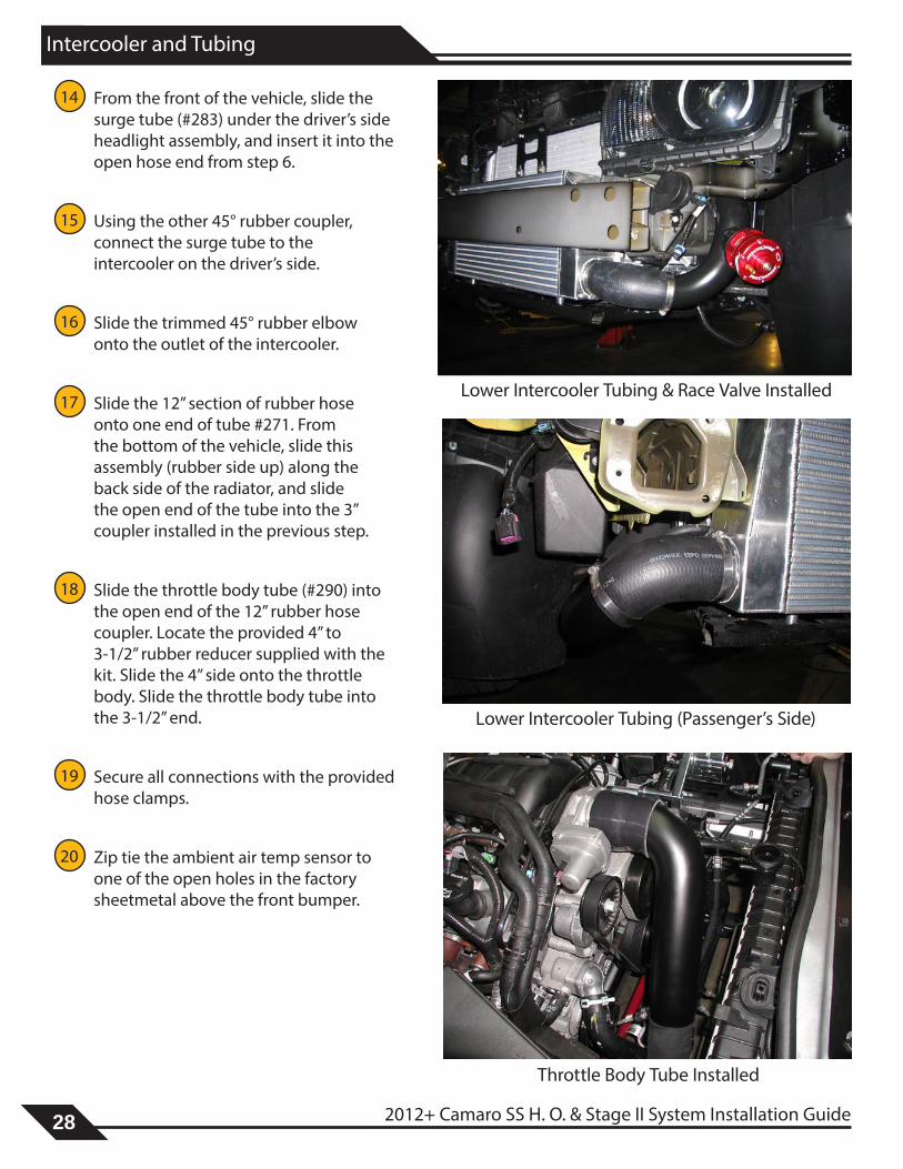
14 From the front of the vehicle, slide the surge tube (#283) under the driver’s side headlight assembly, and insert it into the open hose end from step 6.
15 Using the other 45° rubber coupler, connect the surge tube to the intercooler on the driver’s side.
16 Slide the trimmed 45° rubber elbow onto the outlet of the intercooler.
17 Slide the 12” section of rubber hose onto one end of tube #271. From the bottom of the vehicle, slide this assembly (rubber side up) along the back side of the radiator, and slide the open end of the tube into the 3” coupler installed in the previous step.
18 Slide the throttle body tube (#290) into the open end of the 12” rubber hose coupler. Locate the provided 4” to 3-1/2” rubber reducer supplied with the kit. Slide the 4” side onto the throttle body. Slide the throttle body tube into the 3-1/2” end.
19 Secure all connections with the provided hose clamps.
20 Zip tie the ambient air temp sensor to one of the open holes in the factory sheetmetal above the front bumper.
Lower Intercooler Tubing & Race Valve Installed
Lower Intercooler Tubing (Passenger’s Side)
Throttle Body Tube Installed

2012+ Camaro SS H. O. & Stage II System Installation Guide 29
Windshield Washer Reservoir
1 Mount the (2) windshield washer reservoir brackets together using the supplied 6mm bolts and nuts, then to the vehicle using the provided 5/16” x 3/4” long bolts, washers, and lock nuts. The mounting holes are located on the driver’s side, to one side of the headlight housing.
2 Cut the factory windshield washer wires to remove the plug from the factory harness. Using the supplied solder crimps, attach the factory wires to the supplied plug. Slide the wires into the solder crimps and heat the center of the crimp fitting until the solder melts. Cover the wires with the provided wire loom.
3 Plug the factory washer line into the port on the top of the motor. Plug an additional line into the front of the motor and route to the bottom of the reservoir (see image below). Plug the harness into the new reservoir at this time as well.
4 Slide the new reservoir onto the mounted brackets.
Windshield Washer Reservoir Bracket Hardware Mounted (Front View)
WIndshIeld Washer reservoIr
Windhsield Washer Reservoir InstalledWindhsield Washer Hose Routing
Windshield Washer Reservoir Brackets Mounted

30 2012+ Camaro SS H. O. & Stage II System Installation Guide
Coolant Hose
coolant hose
1 Locate the cooling bag. Slide each elbow onto the provided 1.5” diameter steel tube (see image at right for orientation). Slide the ends of the elbows onto the water pump bung and the upper radiator bung. Using the provided #24 hose clamps, secure each connection.
Tech Tip: Be sure all lines are clear of moving components, i.e. fan/belts/pulleys.
Tech Tip: The factory upper radiator hose can be utilized with the 8 rib belt drive system if trimmed. Utilizing the provided elbows and tube keeps from permanantly modifying your factory parts, as well as creates room for the 12 rib and cog drive systems.
New Coolant Lines Installed

2012+ Camaro SS H. O. & Stage II System Installation Guide 31
Tuning
Note: This section only applies to full systems, which include a handheld tuner. If you do not have a full system, additional tuning will be required before starting the vehicle.
1 Set the parking brake. Plug the X3 handheld into the vehicle’s OBDII port. Proceed to Program Vehicle and then to Upload Stock. Follow the on-screen prompts. The device will read the stock tune from the vehicle.
2 Download SCT Device Updater from www.sctflash.com to your computer. Using SCT Device Updater, click on Get Stock File From Device. This will generate 2 files: 1. “- - -”.bef 2. “vin#”.sul
3 Email the 2 files to [email protected] along with the serial number from the blower and X3 handheld.
4 The tune for your vehicle will be emailed back to you from [email protected]. Upload the tune from your computer to the X3 handheld using the Device Updater Software.
5 Plug the X3 handheld into the OBDII port. Proceed to Program Vehicle, Select Custom Tune, and Select Tune following the on-screen prompts.
Tech Tip: Tuning your vehicle correctly is extremely important and is necessary for proper vehicle operation and safety. If you have any questions regarding tuning your vehicle or with any steps outlined in these instructions, call a technical service representative at (913) 338-2886.
tunInG

32 2012+ Camaro SS H. O. & Stage II System Installation Guide
Fuel System
Tech Tip: Tuner kits do not include fuel injectors. Contact ATI ProCharger for correct size and availability of upgrad-ed injectors.
1 If you have not already done so, de-pressurize the fuel system by completing steps 2-4. Otherwise, skip to step 5.
2 Remove the gas cap to relieve vapor pressure in the fuel tank.
3 Remove the fuel pump fuse from the underhood fuse block (in front of the battery). Crank the engine over for 5 seconds (the engine will not start) to bleed fuel pressure from the fuel lines and fuel rail assembly. Replace the fuel pump fuse. Remove the keys from the ignition.
4 Disconnect the negative battery cable.
5 Place a shop towel underneath the fitting on the driver’s side fuel rail where the stainless steel fuel supply line and fuel rail join. Using the supplied fuel fitting quick-disconnect tool, remove the supply line from the fuel rail, being careful to minimize fuel leakage.
CAUTION: The fuel system should be de-pressurized, but some fuel may leak out when the lines are disconnected. Take the necessary precautions to avoid injury or fire.
6 Disconnect the fuel injector electrical connectors one at a time, labeling them by their corresponding injector location, to ensure proper sequential injector firing order after re-assembly.
7 Disconnect the fuel rail wiring harness from the fuel rail. Remove the fuel rail attaching bolts.
8 Remove the fuel rail assembly as one piece with the injectors still attached and place on a clean work surface, making sure to support the assembly to avoid damaging any of the components.
9 Spread the injector retainer clips to release each injector from the fuel rail. Remove the old injectors and set aside.
10 Lubricate each new injector o-ring seal with several drops of clean engine oil.
CAUTION: Never re-use fuel injector o-ring seals, as they lose elasticity over time and could cause a fuel leak and/or potential fire.
fuel systeM

2012+ Camaro SS H. O. & Stage II System Installation Guide 33
Fuel System
11 Install the retainer clips onto the new injectors. Push each injector into the fuel rail injector socket with the electrical connector facing outward. The retainer clip should lock onto a flange on the fuel rail.
12 Install the fuel rail assembly onto the intake manifold, making sure that the injectors are rotated to line up with their corresponding electrical connectors. Using Loctite 272™ (high temperature thread locker) or equivalent, install the fuel rail bolts and torque to 90 in-lbs.
13 Connect each injector to the factory har-ness.
34 2012+ Camaro SS H. O. & Stage II System Installation Guide
Fuel System

2012+ Camaro SS H. O. & Stage II System Installation Guide 35
Fuel System
FlowCharger Installation
Tech Tip: FlowCharger installations are for Stage 2 systems only. Proceed to the next section if installing a HO sys-tem/kit.
14 Prepare for installation by: removing the carpet from the trunk floor, trunk wheelwell cover, tire repair kit, rear plastic trim panel and passenger side panel carpet.
15 If not already done, disconnect the negative battery cable in the trunk.
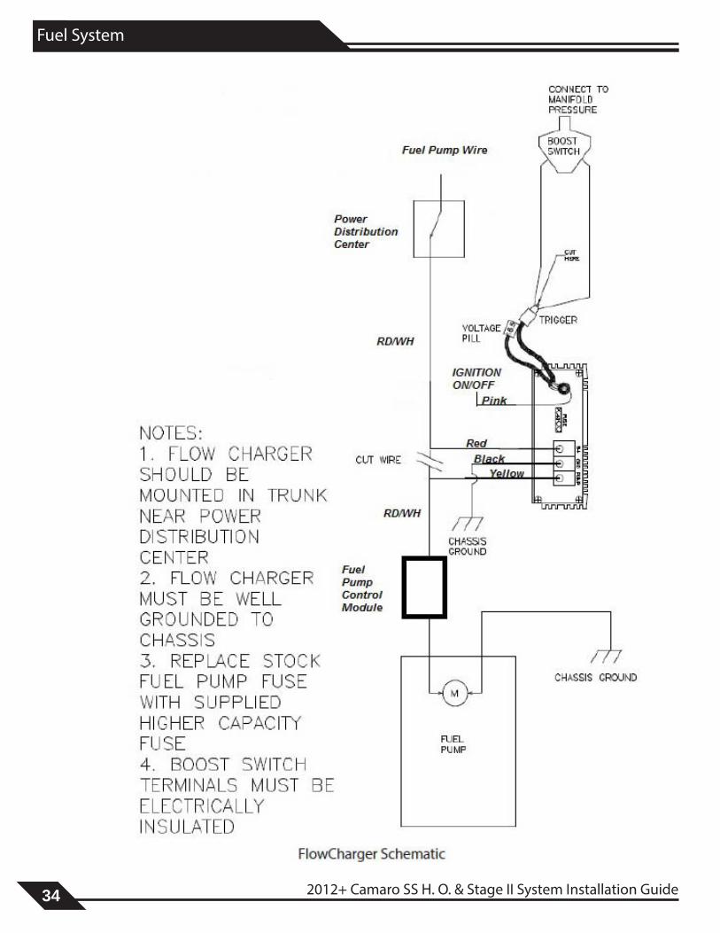
16 Securely mount the FlowCharger to the bottom of the rear deck in the trunk. For high power or high ambient tempertaure useage, FlowChargers should be mounted outside of the spare tire well where it is exposed to cooling air.
17 Route the trigger wiring from the boost switch on the vacuum manifold along back of firewall, through grommet in passenger side of firewall, then through passenger compartment to the trunk next to the fusebox.
18 In the trunk of the vehicle, locate and remove the Fuel System Control Module (FSCM) fuse (position F15 on some models) from the fusebox on the passenger side.
19 Remove the fusebox from the passenger side of the trunk and remove the rear cover of the fusebox to expose the wiring harness.
FlowCharger Mounted
Trigger Wires and Trunk Fusebox
Fusebox Disassembled

36 2012+ Camaro SS H. O. & Stage II System Installation Guide
Fuel System
20 Locate the wire (red with white stripe) coming from behind the FSCM fuse and cut a couple inches back from fusebox to allow splicing onto both ends.
21 Connect the FlowCharger wiring as shown in the wiring schematic. Be sure the FlowCharger has a solid ground contact.
Tech Tip: The pink power wire should be connected to a switched ignition power source, which can be found in the engine bay fuse panel. (Specific fuse location varies by model).
22 Assemble and mount the fusebox back onto trunk panel. Re-install the passenger side panel carpet and rear plastic trim panel.
23 Replace the gas cap and negative battery cable. Re-install the fuel supply hose by pressing the fitting onto the fuel rail fitting until a snap is heard.
24 Check the new injectors for leaks by per-forming the following procedure:
A. Turn the ignition to the “on” position for 2 seconds. Don’t start the engine!
B. Turn the ignition off for 10 seconds. C. Turn the ignition to the “on” position. D. Check for fuel leaks at both ends of
each injector and at the fuel supply hose fittings.
25 Proceed to the next section if no leaks are detected, otherwise review the installation and remedy any problems.
FlowCharger Installed
FSCM Wire Location

2012+ Camaro SS H. O. & Stage II System Installation Guide 37
PCV System
L99 MODELS
1 If not already done, remove the PCV line that runs from the air intake system to the passenger’s side valve cover bung.
2 Install the supplied 36” long 3/8” hose from the passenger’s side valve cover to the rear of the blower, on the inlet side of the supercharger. This line will be at-tached to the air filter later in the install.
3 Remove the PCV line that runs from the intake manifold (just behind the throttle body) to the rear of the driver’s side valve cover.
4 Run the supplied 36” long 3/8” hose from the intake manifold to the rear driver’s side PCV bung. This line replaces the line removed in Step 3.
5 Cut the line from Step 4 in half, and in-sert the supplied check valve, reconnect-ing these lines to each end of the check valve. Be certain the arrow on the check valve points towards the intake manifold connection, preventing boost from en-tering the valve cover.
Pcv systeM
CHECK VALVE
New PCV Routing With Check Valve
Remove Factory PCV Lines
REMOVE (2) LINES
Factory PCV Bungs
(2) PCV BUNGS WITH STOCK LINES RE-

38 2012+ Camaro SS H. O. & Stage II System Installation Guide
PCV System
LS3 MODELS
1 If not already done, remove the PCV line that runs from the air intake system to the passenger’s side valve cover bung.
2 Remove the “U” shaped PCV line that is located behind the throttle body, and connects the intake manifold and crank-case valley.
3 Place the supplied 3/8” vacuum cap over the intake manifold bung, and secure with the provided #6 hose clamp.
4 Cut a 6” length of 3/8” rubber hose and install it onto the crankcase valley bung. Slide the provided plastic tee fitting onto the opposite end.
5 Cut a 6” length of 3/8” rubber hose and install it onto the passenger side valve cover bung. Slide the opposite end into the plastic tee fitting.
6 Attach the remaining 3/8” rubber hose to the open end of the plastic tee, and route it along the firewall to the driver’s side. This will be connected to the air filter in a later step.
Remove Factory PCV Hose
Remove “U” Shaped Hose
New PCV RoutingPlastic Tee Fitting
Plug Installed
To Air Inlet
To Valve Cover
To Valley

2012+ Camaro SS H. O. & Stage II System Installation Guide 39
Vacuum Manifold
1 Locate the 1⁄2” ID brake booster hose that runs along the back side of the engine near the firewall. The line is connected to the brake booster located on the driver’s side.
2 Using a hose cutter, remove a 3-1⁄2” long section of the hose.
3 Assemble the vacuum manifold using the provided barb fittings and plugs. Install the supplied vacuum manifold and securely clamp in place using the supplied #6 hose clamps, making sure that there are no vacuum leaks at the splice points.
Warning: Improper clamping of the splice into the brake booster hose could cause a vacuum leak and could cause the power brakes to become inoperable. Use extreme caution in installing the vacuum manifold to prevent any possible leaks.
4 Attach the supplied 3⁄16” vacuum hose to one of the 3⁄16” barb fittings on the installed vacuum manifold, then route and attach to the ProFlow anti-surge valve vacuum port. Attach a boost gauge to the other 3⁄16” barb fitting. If you are not going to use a boost gauge, remove the 3⁄16” barb fitting that isn’t being used and replace with the supplied pipe plug.
5 Secure all vacuum hoses to their fittings with zip ties.
Tech Tip: When installing a race valve, the assembly utilizes push lock fittings and nylon hose, replacing the standard barb fitting and rubber hose. Thread the push lock fitting onto the vacuum manifold and race valve, and simply push the nylon line into each fitting to create a secure connection.
vacuuM ManIfold
Plug
Barb Vacuum Manifold
Brake Booster Hose
Vacuum Manifold Installed

40 2012+ Camaro SS H. O. & Stage II System Installation Guide
Final Assembly
fInal asseMbly
STANDARD INLET ONLY
1 Re-install the factory engine cover. Remove the oil fill cap, slide the cover into the (2) rear clips, and push the cover down onto the fuel rails. Re-install the oil fill cap.
2 Locate the air inlet bag. Slide the provided 3.75” coupler onto the inlet of the blower, followed by the air inlet tube (#272). The end with the tighter radius needs to be inserted into the blower to create clearance around the auxilary power supply.
Tech Tip: Bending the auxilary battery terminal down and out of the way may be necessary for proper air inlet tube clearance. Loosening and rotating the power wire provides slack for relocation.
3 Drill a 3/8” hole into the end of the air filter that is supplied with the kit.
4 Slide the provided 90° plastic elbow onto the open end of the PCV line that was installed in the PCV section. Slide the open end of the elbow into the hole that was drilled into the air filter.
5 Slide the air filter onto the air inlet tube. Adjust the tube/filter/hose coupler and secure the connections with the provided hose clamps.
Tech Tip: Proceed to Step 6 for completion of the final assembly instructions.
PCV Line Installed Into Air Filter
Air Inlet Assembly Installed

2012+ Camaro SS H. O. & Stage II System Installation Guide 41
Final Assembly
STAGE II INLET ONLY
Tech Tip: The Stage II inlet requires re-positioning of the auxilary battery post. A new bracket is included.
1 Re-install the factory engine cover. Remove the oil fill cap, slide the cover into the (2) rear clips, and push the cover down onto the fuel rails. Re-install the oil fill cap.
2 Using a 1/4” drill bit, drill out the spotwelds (4x) holding the auxilary battery post bracket to the inner fender. Slide the battery post off of the bracket and remove the bracket from the vehicle. Install the supplied bracket using the provided 1/4-20 screws, washers, and nuts. Slide the battery post into the new bracket.
3 Locate the air inlet bag. Slide the provided rubber coupler onto the inlet of the blower, straight end onto the blower, followed by the air inlet tube (#289).
4 Drill a 3/8” hole into the end of the air filter that is supplied with the kit. Slide the provided 90° plastic elbow onto the open end of the PCV line that was installed in the PCV section. Slide the open end of the elbow into the hole that was drilled into the air filter.
5 Slide the air filter onto the air inlet tube. Adjust the tube/filter/hose coupler and secure the connections with the provided hose clamps.
6 Re-install the front fascia. Be sure to connect the wiring harness to the fascia. Install all of the factory hardware for fascia installation. Install the fasteners that secure the wheel liners.
7 Re-install the wheels and tires if removed.
8 Reconnect the battery.
Stage 2 Air Inlet Assembly Installed
Auxilary Battery Post RelocationBracket Installed

42 2012+ Camaro SS H. O. & Stage II System Installation Guide
Final Assembly
CONGRATULATIONS! YOU HAVE COMPLETED THE INSTALLATION OF YOUR NEW PROCHARGER SUPERCHARGER SYSTEM. READ THE FOLLOWING PAGES CAREFULLY FOR OPERATION AND MAINTENANCE INSTRUCTIONS, AS WELL AS WARRANTY INFORMATION.
2012+ Camaro SS H. O. & Stage II System Installation Guide 43
Operation and Maintenance
Cold StartingNever race your engine and ProCharger supercharger when your engine is cold. Allow the water temperature to climb into operating range for several minutes before driving above 2,500 rpm, to ensure adequate oil lubrication.
Fuel QualityWith a properly installed intercooled ProCharger supercharger system, detonation should not occur. For the best performance and reliability, use premium grade fuel (91 octane or higher). Listen for signs of detonation after refueling, and after replacement or modification of any fuel system component(s). If detonation occurs, reduce the throttle and locate the source.
Ignition System MaintenanceIf your spark plugs are more than a year old or have more than 10,000 miles logged, you should consider changing them before driving your vehicle under load. Spark plug wires should be changed if visibly damaged or when resistance exceeds factory specifications.
Air Filter MaintenanceYour air filters should be cleaned periodically, potentially as often as every 10,000 miles or 6 months, even though a service interval of 50,000 - 100,000 miles is quoted by the manufacturer under normal driving conditions. A clogged air filter will result in decreased boost levels and vehicle performance. Be sure to re-oil the cleaned filter before re-installing. Always operate your vehicle with an air filter; failure to do so may result in damage to your ProCharger supercharger and personal injury!
Belt ReplacementThe serpentine belt, which turns your ProCharger supercharger, will stretch after initial run-in, and should be retightened after the first hundred miles. Tighten the belt sufficiently to avoid slippage, but do not overtighten. Overtightening the belt could cause damage to the ProCharger supercharger’s precision bearings. When re-installing the belt, use the belt routing diagram in this manual. If you reuse a thrown belt and find that it needs frequent re-tightening, the belt is damaged and should be replaced. Gates Micro-V belts can be bought from ATI or from your local parts store.
ProCharger Oil Change IntervalsThe first oil change should be performed at 500 miles and at 6,000 mile intervals thereafter. Clean the drain plug after every oil change. Drain oil by removing the drain plug. Clean off the drain plug before re-installing.
oPeratIon and MaIntenance

44 2012+ Camaro SS H. O. & Stage II System Installation Guide
Operation and Maintenance
ProCharger Oil LevelThe ProCharger supercharger’s oil level must be checked periodically to ensure the proper lubrication. The dipstick can be loosened using a flat blade screwdriver or a coin. When installed, the oil level should remain between the minimum (MIN) and maximum (MAX) indicators at all times.
Warning: Filling the ProCharger higher than the maximum level on the dipstick can lead to bearing and seal damage. The supercharger is a sealed unit and should not normally require the addition of oil between service intervals. If excessive usage is noted, the unit should be sent to ATI for inspection and repair. The dipstick fitting should be firmly tightened after changing or checking the oil level.
GeneralWhen removing the dipstick, be sure to retain the nylon washer. A spare nylon washer and o-ring is included. Use only the ATI supplied nylon washer and o-ring when servicing the oil dipstick and drain plug. A discoloration of the oil and residue on the drain plug may occur during the initial oil changes. This is normal and will gradually decrease. For the proper positioning of the ProCharger supercharger, the serial tag should be pointing upwards. Installing the ProCharger supercharger in another position will cause inadequate oiling and supercharger failure. If you have any questions about the maintenance of your supercharger, contact ATI.
Warning: The supercharger contains no oil from the factory. The unit must be filled prior to use. Use only ATI supplied oil in your ProCharger. The ATI oil has been specially formulated for the bearings in the ProCharger and use of oil other than that supplied by ATI will void your warranty.
Magnetic Drain Plug (hex head)
Sealed Plug (socket head)
Dipstick (flat head)
Sealed Plug (socket head)

2012+ Camaro SS H. O. & Stage II System Installation Guide 45
Limited Warranty
Accessible Technologies, Inc. (ATI) provides a limited twelve (12) month warranty on the ProCharger supercharger against defects in materials and workmanship unless otherwise specified. This limited warranty starts on the date of original purchase from your local dealer, or date of shipment from the factory. This limited warranty coverage is extended only to the original owner and excludes hoses, sleeves, and electronic components manufactured by other companies. IF THE SUPERCHARGER’S DRIVE RATIO IS ALTERED IN ANY WAY FROM THE FACTORY SETTING, WARRANTY COVERAGE IS VOID. USE OF ANY PULLEY NOT MANUFACTURED OR SUPPLIED BY ATI VOIDS ALL WARRANTY COVERAGE. ATI’s warranty obligations are limited to the terms below:
ATI agrees to honor a warranty claim at its sole discretion and only after inspection at the ATI factory. No warranty will be honored if any part of the product is found to have been improperly installed, tampered with, mishandled, or misused in any way. Disassembly of the ProCharger supercharger or removal of the ProCharger supercharger’s serial plate voids all warranties. Claims for freight damages should be directed to the freight company.
If ATI’s limited warranty applies, your product will be repaired or replaced at ATI’s discretion and shipped back. If the limited warranty does not apply, ATI will advise you of the specific reason, cost of the repair, and delivery time. After advising you of this information we will, at your option, either proceed with repairs or return your product to you in the state in which it was received. In either case the product will be shipped to you, insured at replacement value. Therefore, you will pay the return shipping and insurance charges if ATI’s limited warranty does not apply to your product.
THE WARRANTY AND REMEDIES SET FORTH ABOVE ARE EXCLUSIVE AND IN LIEU OF ALL OTHERS, ORAL OR WRITTEN, EXPRESS OR IMPLIED. THE DURATION OF ANY AND ALL WARRANTIES ON THE PRODUCTS DISCUSSED ARE LIMITED TO THE PERIOD IDENTIFIED ABOVE. ATI IS NOT RESPONSIBLE IN ANY EVENT FOR DIRECT, SPECIAL, INCIDENTAL OR CONSEQUENTIAL DAMAGES. No ATI dealer, agent, or employee is authorized to make any modification, extension, or addition to this warranty.
To obtain service under this warranty you must do the following during the warranty period:
Phone ATI (913-338-2886) and provide us with the following information:
- ProCharger supercharger serial number. - Vehicle year, make, model, engine modifications, and other modifications. - Description of perceived issue.
If a solution to your issue can not be found after the above phone consultation, you will be assigned a return authorization number (RMA). You must then properly package and ship your product, at your expense, to the ATI factory. The product should be carefully packaged in a rugged box.
Include the following information inside the box with your product:
- Copy of your original invoice or receipt. - Name, address, and daytime telephone number. - Return authorization number (RMA). - Vehicle year, make, model, engine modifications, and other modifications. - Description of perceived issue.
Clearly mark the warranty claim number on the top and one side of the box in characters at least 2” tall. Properly package the product and ship it, prepaid and insured for the retail value of the component(s) being returned, to the following address:
Accessible Technologies, 14801 West 114th Terrace, Lenexa, Kansas 66215
lIMIted Warranty

46 2012+ Camaro SS H. O. & Stage II System Installation Guide
ProCharger Extended Coverage
The ProCharger Extended Coverage Program extends the ProCharger warranty coverage for an additional twenty-four (24) months, for a total of thirty-six (36) months or three years of coverage. This extended coverage applies to parts for the ProCharger supercharger head unit only and does not include other system components. With your extended coverage registration, you will receive two (2) additional boxes of ProCharger Supercharger oil.
Under the extended coverage program, Accessible Technologies, Inc. (ATI) will repair or replace any component within the supercharger head unit which is found to be defective. Only the supercharger head unit itself is included in the extended coverage.
Service under the extended coverage program is obtained through the same process as described in the Limited Warranty.
Race kits are not eligible for the ProCharger Extended Coverage Plan
To qualify for the ProCharger Extended Coverage:
• Only the original owner of the ProCharger supercharger is eligible.
• Completion of the Extended Coverage Registration Form is required, along with a $49 registration fee. This form must be completed in its entirety, and must be submitted along with payment within 30 days from the date of original purchase from your local dealer or date of shipment from the factory.
• Participants must have a ProCharger P-1SC, P-1SC-1, C1, or C2 supercharger head unit using the maximum warranted boost level. All terms and conditions within “The Limited Warranty” apply. Acts resulting in disqualification include but are not limited to the following:
- Disassembly or modification the ProCharger supercharger.
- Removal or attempted removal of the ProCharger drive pulley(s).
- Removal or attempted removal of the ProCharger supercharger serial number plate.
- Removal or attempted removal of the compressor housing or transmission case.
• Participants agree to properly maintain the ProCharger supercharger and provide proof of compliance with the following recommended maintenance:
- Change the ProCharger supercharger oil after the initial break-in period of 500 miles (automotive) or 15 hours (marine).
- Change the ProCharger supercharger oil every 6,000 miles after the initial break-in period.
- Use only the specified amount of ProCharger Supercharger oil in the ProCharger supercharger.
- Inspect and clean the magnetic drain plug at every ProCharger supercharger oil change.
- Check the ProCharger supercharger oil level frequently.
ProcharGer extended coveraGe

ProCharger Extended Coverage Program Registration Formcu
t alo
ng th
e do
tted
line
cut a
long
the
dott
ed li
ne
Name:_________________________________
Address:_______________________________
City:___________________________________
State:________________ Zip:____________
Country:_______________________________
Daytime phone:_________________________
Evening phone:_________________________
E-mail:_________________________________
Age 18 - 24 25 - 34 35 - 44 45 - 54 55 and up
Income $15,000 - $29,000 $30,000 - $44,000 $45,000 - $69,000 $70,000 and up
What magazines do you read?
Car & Driver Car Craft Chevy High Performance Four Wheel and Off Road Hot Rod Motor Trend Muscle Mustangs and Fast Fords GM High-Tech Performance 5.0 Mustang Super Street Mustang Monthly Truck Trends Popular Hot Rodding Road & Track Super Chevy Truckin’ Street Truck
Date of Purchase:_______________________
Purchased From:_______________________
ProCharger Serial #:_____________________
Vehicle Year:___________________________
Vehicle Make:__________________________
Vehicle Model:_________________________
Please rank in order of importance starting with 1 being most important.
Which information sources most influenced your decision to purchase a ProCharger system?
___ Magazine advertising ___ Dealer recommendation ___ ProCharger Brochures ___ Witnessed performance on a car ___ Test drive ___ Magazine editorials ___ Friends ___ Conversations with ATI technicians ___ Web Site (please specify)___________ ___ Other (please specify)__________
What most influenced your decision to purchase a ProCharger system?
___ Reliability ___ Standard warranty ___ Extended coverage warranty ___ Performance ___ Quiet operation ___ Removability (ability to return car to stock) ___ Cost ___ Ease of Installation
Who installed your ProCharger system? Self Dealer Other ________________________ Have you own a forced induction system previously? Yes No If yes: Supercharger: Brand(s)_______________________ Vehicle(s)_____________________________
Turbocharger: Brand(s)_______________________ Vehicle(s)_____________________________
I have read and understand the policy for the ProCharger Extended Coverage Program. I have not and will not modify my ProCharger supercharger in any way during my participation in the extended coverage program. I have read and answered all questions on this form. I have enclosed my check for $49, payable to ATI, for enrolling my ProCharger supercharger (serial number indicated above) in the extended coverage program for an additional twenty-four (24) months beyond the standard limited warranty period of twelve (12) months.
Signature_____________________________________________ Date_____________________
Mail this completed registration form with a $49 check to ATI at: 14801 West 114th Terrace, Lenexa, KS 66215. If you have any questions, contact us at [email protected] or (913) 338-2886 8:30 AM - 5:30 PM CST, Monday - Friday.
Return this completed form and a $49 check within 30 days of original purchase.

This Page is Intentionally Left Blank

This Page is Intentionally Left Blank

Accessible Technologies, Inc. 14801 W. 114th Terrace
Lenexa, KS 66215 Phone: 913.338.2886
Fax: 913.338.2879 [email protected]
Accessible Technologies, Inc. ©2014 ATI, All Rights Reserved
Part Number PMGT1A-004 Rev. G
*PMGT1A-004*


