Page 1
PASSION FOR POWER.
Assembly instructionENYSTAR Distribution Boards
up to 250 AIntended to be operated by ordinary persons (DBO)
in accordance with IEC 61439-3
Download at www.hensel-electric.de/61439
Page 2
2
Design fast, simply, more clever
www. .eu
Page 3
3
Assembly
Video
Distribution Boards up to 250 Ain accordance with IEC 61439-3
• combinable enclosure system
• with doors
• degree of protection IP 66
• made from polycarbonate
• protection class II, �
Standard-conforming rating of distribution boards intended to be operated
by ordinary persons (DBO) according to IEC 61439-3 4
General and specifi c requirements 5
Recommendation for outdoor installations, humid and wet areas and locations 6
Formation of condensed water 7
System design 8
Assembly
Positioning of enclosures according layout, frame removal 9
Combination of enclosures, connectors, wall separators 10 - 11
Closing plates, fl anges, cable insert, box fi n 12 - 13
Extension frame 14
Installation
Wall-mounting 15
Measures against condensation forming in enclosures 16
Canopy 17
Changing door hinges, convertion of door locks 18 - 19
Device installation
Mounting plates, DIN rails 20
Covers - protection against access to hazardous parts, sealing 21
Changing connection direction with HRC 00C/HRC 1 fuse switch disconnectors 22
Equipment openings and partition 23
Wiring
Busbar system, applicaton possibilities of busbar boxes 24 - 25
Terminals 26
Bending wiring strips 27
PE and N terminals 28
Aluminum conductors 29
Routine verifi cation / inspection, routine test report (check list) 30 - 31
Manufacturer‘s marking 32
Declaration of conformity (check lists for the manufacturer of an assembly) 33
Declaration of conformity of ENYSTAR distribution boards 34
Hensel specialist consultant on-site at www.hensel-electric.deInfo
Page 4
4
ENYSTAR
Standard-conforming rating of distribution boards intended
to be operated by ordinary persons (DBO) according to IEC 61439-3
BLACK BOXwith 4 interfaces
Combinable enclosure system,
insulation-enclosed, total insulated,
degree of protection IP 66,
for the assembly of ENYSTAR distribution
boards up to 250 A intended to be operated
by ordinary persons (DBO) in accordance with
IEC 61439-3
The requirements for all installed electrical func-
tions within the assembly have been proved com-
pliance with the applicable requirements of
IEC 61439-3.
Inc
and RDF must be specifi ed in the documenta-
tion.
ENYSTAR
Distribution Board
- For protected outdoor installation
- Degree of protection IP 66
- Combinable enclosure system,
extendable in all directions
- 4 enclosure sizes in grid of 90 mm
- EMC complient busbar system
- Wall-mounting
- Electric circuit / fi nal circuit
- Circuit-breaker up to 250 A
- Switch disconnector up to 250 A
- Fuse switch disconnector up to 250 A
- Bus-mounted fuse base up to 63 A
- Cable connection from top / from bottom
- Connection: conductors from copper / aluminum
- Optional connection of CEE sockets according to
EN 60309 and sockets with earthing contact
according to DIN 49440-1
The new EN 61439 - the standard for the construction of switchgear assemblies - brings changes that affect the plan-
ning of a switchgear assembly. In addition, new tasks and responsibilities are awaiting the manufacturer of a switchgear
assembly.
Decisive for the optimal functioning of a switchgear assembly under operating conditions is the correct rating of the in-
terface characteristics of the assembly. For this purpose, the assembly is considered as BLACK-BOX with four interface
characteristics which shall ensure compatibility with the ratings of the circuits to which it is connected and the installation
conditions and shall be declared by the assembly manufacturer using the criteria identifi ed below.
Assembly considered as BLACK BOX with the four interface characteristics
according to IEC 61439-3
Installation and
ambient conditions
Connection to the
electrical network
- Distribution board up to 250 A
- Protection class II up to rated current of 250 A
- Flexible through standardised and tested kits
- Spacious connection areas
- Fulfi ll the requirements for operation by ordinary
persons (DBO)
- Rated voltage UN = 690 V a.c. / 1000 V d.c.
- Rated current IN up to 250 A
- Circuit-breaker up to 250 A
- Switch disconnector up to 250 A
- Fuse switch disconnector up to 250 A
- 5-conductor systems
- Cable connection from top / from bottom
Operation and
maintainance
Circuits and
consumers
Page 5
5
ENYSTAR
Requirements for distribution boards intended to be operated
by ordinary persons (DBO) according to IEC 61439-3
Operation also by
electrotechnical unskilled persons
Devices which must only
be operated by skilled
persons, must be installed
in a separate area which
can only be opened using
a tool
General requirements concerning distribution boards
1. Clear separation between operation area and distribution area
For areas in distribution boards to which unskilled persons have access,
standards require special protective measures: - Life parts are to be protected against accidental contact by a cover.
- Devices, which may be operated only by an electrical skilled person,
are to be arranged in a separate area, which is to be opened only with tool.
2. Fast and safe operating of the intended devices,
e.g. series built-in equipment and switching devices
Additional specific requirements when used in commercial and industrial applications:
1. High degree of protection IP 66: dust-proof and waterproof
2. Robust material for use in rough environments:
high-quality thermoplastic material for high mechanical loads.
3. Corrosion resistance:
Material resistant to corrosion by atmospheric humidity or industrial processes.
Operating areas for
unskilled persons can be
reached quickly and easily
via door locking with hand
operation
Requirements in accordance with IEC 61439-3:
1. Only installation equipment, like series built-in
equipment, fuses up to 63 A, circuit-breakers
and IT-components are permitted. For the ac-
cess a tool-operated door locking facility is NOT
necessary.
2. Other switching devices must be installed be-
hind separate lids or doors, which can only be
opened using a tool:
protection against direct contact with
hazardous live parts IP XXC.
To the following areas only an electrical skilled
person may have access:
feeding-in
back-up fuse
outgoing terminals.
Therefore access is possible only with appropri-
ate tools. The access can be prevented by op-
tionally lockable doors. Electrotechnical unskilled
persons have no access here.
Access and operation only by electrical skilled persons
Page 6
6
ENYSTAR
Recommendation for outdoor installations,
humid and wet areas and locations
degree of protection IP X 4
with non-direct jets of water within occasional
cleaning procedures, e.g. agriculture
degree of protection IP X 5
with non-direct jets of water within operational
cleaning procedures, e.g. carwash
degree of protection IP X 5
and additional consultation with the
manufacturer:
with direct jets of water within occasional cleaning
procedures of enclosures, e.g. butcher’s shop
1.2. Minimum requirements for electrical equipment,
that must withstand higher environmental stresses:
„Protected outdoors“
Electrical equipment has to be protected from precipitation (like rain, snow or hail)
as well as from direct sunlight.
„Non-protected outdoors“
Electrical equipment can be exposed to precipitation or direct sunlight.
With both assembly sites the climatic effects on the installed equipment must be observed, for example,
high or low ambient temperatures or condensation.
Note for outdoor
installation:
1. Requirement
Protection against ingress
of water for all electrical
equipment (devices) with
the appropriate encapsula-
tion (2nd characteristic
numeral)
1.1. Minimum requirement for electrical equipment:
Degree of protection
IP X 1
Degree of protection
IP X 1
Degree of protection
IP X 3
indoors protected outdoors unprotected outdoors
Country-specifi c
requirements have
to be observed!
Requirements of German standard DIN VDE 0100 Part 737
for compliance with IP degree of protection
4.1 Electrical equipment must be selected taking into account the external influences to which they
may be exposed. Proper operation and the effectiveness of the required degrees of protection
must be assured.
Note: Data from the manufacturer!
2. Requirement of German
Standard DIN VDE 0100
Part 737
Country-specifi c
requirements have
to be observed!
Page 7
7
ENYSTAR
Formation of condensed water
Condensed water only forms in enclosures with a higher degree of protection than IP 54 due
to temperature difference from inside to outside. Humidity can not evaporate because of the
high degree of protection of the enclosure.
How does condensed water
occur in enclosures with a
high degree of protection?
Here condensed water can be formed
dependent on the weather, high air
humidity, direct sunlight and temperature
differences compared to the wall.
In areas where high levels of air humidity
and large temperature fl uctuations are
expected e.g. in laundry rooms, kitchens,
car washes etc.
Formation of condensed water in protected out-
door installations (protected against weather
infl uences) or unprotected outdoor installations:
Formation of condensed water for
indoor installations:
How does condensed water
occur in enclosures with a
high degree of protection?
System switched on. The internal temperature is higher than the external
temperature due to the power dissipation of the
built-in devices.
System switched on. The warm air inside the enclosure attempts to accu-
mulate moisture. This comes from outside through
the seal as the enclosures are not gas-tight.
The internal temperature is reduced by cooling
down the system e.g. by switching off the loads.
The cooler air emits moisture which is collected as
condensed water on the cooling inner surfaces.
System switched off.
Page 8
8
ENYSTAR
System design
Standard tool operation for slotted
screwdrivers and triangle
(option square, double bit)
Locking facilities with keys prevent the
unauthorized opening of doors
Hand operated doors in areas to which
unskilled persons have access for oper-
ating devices
Operation
Clear separation of the
operation areas for unskilled
persons and access/opera-
tion areas for skilled persons
(electricians).
Different enclosure depths
allow the installation of equip-
ment of different heights.
With an extension frame the
depth of the enclosure sizes
3 and 4 can be extended by
50 mm.
The modular structure of
enclosures in grid of 90 mm
allows a free confi guration of
the outer form.
Combinable in all directions
to follow given requirements
on site.
1
2
3
4
Enclosure depth
with hand operation
186
with tool operation
Extension frame
for extending installation depths
by 50 mm with hand operation
���
�����
with tool operation
Page 9
9
ENYSTAR
Assembly
Removal of the frames
with door
Unscrew and remove the frame
from the bottom part together
with the door.
Positioning of enclosures
Assembly of enclosures
according to layout
Page 10
10
ENYSTAR
Assembly
Combination of enclosures
Combination of enclosures
with connectors and wall
separators
Fast assembly and mounting
All necessary gaskets are integral part of the
enclosures. The enclosures are interconnected
among themselves by easily pushing-in of con-
nectors. No tools are necessary.
Connectors are attached to the enclosures in
suffi cient number. For reconstruction or exten-
sions of existing distribution boards connectors
FP GV 10 (set consists of 10 pieces) can be
supplemented.
The connection of enclosures is not only co-ordi-
nated with enclosures of the same size.
By means of wall separators also different sized
enclosures can be combined.
Wall separators provide for high rigidity and tight-
ness at the connection points of the enclosures,
degree of protection IP 66.
At this point a wall separator is nec-
essary for the enclosure combination.
box size 2 box size 1
box size 1
box size 1
box size 1
box size 1
box size 3
box size 1 box size 2
box size 3 box size 2
box size 4
box size 2
box size 3
box size 1
box size 3
box size 1
box size 2
box size 1
box size 3
Page 11
11
ENYSTAR
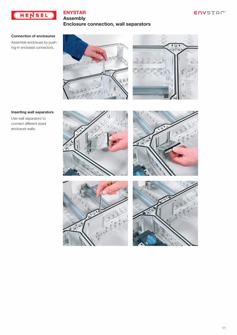
Assembly
Enclosure connection, wall separators
Connection of enclosures
Assemble enclosues by push-
ing-in enclosed connectors.
Inserting wall separators
Use wall separators to
connect different sized
enclosure walls.
Page 12
12
ENYSTAR
Assembly
Closing plates, fl anges, cable insert
Closing of enclosure walls
with fl anges for cable entry
Insert fl anges for cable entry
into open outer walls of the
distribution board and fi x them
with enclosure connectors.
A wide range of fl anges for the
cable entry is available.
Closing walls via closing
plates
Insert closing plates into
openings of outer walls of the
distribution board and fi x them
with enclosure connectors.
Cable glands
Insert cable gland into the
appropriate knockout and
fasten with lock nut.
Cable entry - opening
knockouts in fl anges
Knock out the appropriate
cable entries within fl anges
with screwdriver.
Page 13
13
ENYSTAR
Assembly
Cable inserts, box fi n
Installation of cable inserts
Saw the box fi n.
Afterwards the cable insert
is mounted and fi xed via
enclosure connectors and the
rubber entries can be inserted.
Insert the cable into the
box from the front.
Insert cable and fi x it with
the cable ties.
������Adjust stepped grommet
on the cable diameter.
Box fi n
provides an easier wiring
across two boxes.
Saw out fi n in box wall.
Insert box fi n and fi x via fi xing
wedges.
Page 14
14
ENYSTAR
Assembly
Extension frame
Installation of extension
frame
Fix attachments for extension
frame in base of enclosure.
Place extension frame on base
of enclosure and screw it.
Support for protection cover is
adjustable in height.
Click protection cover into
place depending on the height
of the electric devices
(height adjustable).
FP ZR ..
Extension frame
for extension of the installa-
tion depth by 50 mm
Page 15
15
ENYSTAR
Installation
Wall mounting
External brackets made
from stainless steel
for external box fi xing
��
��
��
��
�
����
Mounting profi le
for wall-mounting of
ENYSTAR distribution boards,
steel profi le,
length 1980 mm
FP MS 1
Note:
Please fi x mounting profi le in vertical position
as possible in order to give occation to cable
routing behind the assembly.
For cutting to the required length fi x mounting profi le
for example with a clamp to a desk.
����
�� �� �
��
Fixing matrix of mounting
profi le
Transport
Regarding transportation it is recommendable to protect the assembly
against defl ection. For that please screw the assembly to a solid timber.
FP AL 40 (4 pieces)
Page 16
16
ENYSTAR
Installation
Measures against condensation forming in enclosures
Ventilation fl ange
FP BF 36
for ventilation of ENYSTAR
distribution boards in the event
of extremely high internal
temperatures or a risk of water
condensation.
For vertical installation on box
walls, degree of protection
IP 44
FP BF 36
FP BF 36
Pressure compensation
element BM 32
for the reduction of conden-
sation by pressure compen-
sation in power distribution
systems
BM 32
BM 32
66
15,7
M32x1,5
30,7
Combi climate glands
KBM / KBS ...
for reduction of condensa-
tion by pressure compensa-
tion
Via an inserted climate mem-
brane they ensure pressure
compensation between enclo-
sure interior and ambient air.
Ingress of water through the
calbe gland is prevented.
The degree of protection of
the enclosure is obtained!
KBM ...
KBS ...
paußen = pinnen
paußen = pinnen
Page 17
17
ENYSTAR
Installation
Canopy
Mount the fl ange with pre-
assembled canopy on upper
housing wall.
Canopy for the unprotected
installation outdoors
In case of box assembly con-
nect trusses with stop plate.
Mount canopy and/or canopy
end plate
Hint:
Insert canopy end plate under
the canopy until it hits back-
stop.
FP DB 27
FP DB 36
Mi DB 01
Page 18
18 18
ENYSTAR
Installation
Changing door hinges
Changing door hinges
Hint:
When changing the door stop
in circuit-breaker boxes the
protection cover must be tur-
ned around.
Remove door hinge from the
door frame.
Then remove interlocking
device for the door lock from
the frame.
Insert interlocking device and
door hinge on the other side in
the frame.
Page 19
19
ENYSTAR
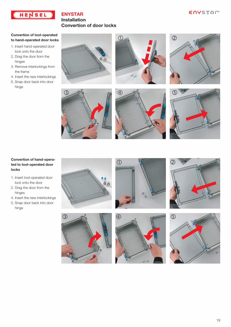
Installation
Convertion of door locks
Convertion of tool-operated
to hand-operated door locks
Convertion of hand-opera-
ted to tool-operated door
locks
1. Insert hand-operated door
lock onto the door
2. Drag the door from the
hinges
3. Remove interlockings from
the frame
4. Insert the new interlockings
5. Snap door back into door
hinge
1. Insert tool-operated door
lock onto the door
2. Drag the door from the
hinges
4. Insert the new interlockings
5. Snap door back into door
hinge
Page 20
20
ENYSTAR
Device installation
Mounting plates, DIN rails
Device installation on
mounting plates or DIN rails
Fasten installation devices on
mounting plates with self-
threading screws.
Screw mounting plate onto
base of box.
Mount DIN rails direktly onto
base of boxes or on spacers
FP DS 02 in heights of
29.5 mm or 53.5 mm.
FP DS 02
Page 21
21
ENYSTAR
Device installation
Covers, sealing
Then screw the frame with
door and cover onto base of
enclosure.
Seal the cover.
Device installation into
covers
Pre-drill the cut-outs at the
corners and saw them out of
the cover.
Use a piercing saw with coarse
toothed saw blade for plastics.
Install device.
Snap cover into door frame
from the rear.
Afterwards, screw door-frame
with door and cover onto base
of enclosure.
Installation depth for equipment
installation in covers
Sealing
For installation in all enclosures
except circuit breaker boxes.
Sealing device is screwed on
enclosure bottom.
Open pre-moulded opening for
sealing device (drill Ø 5 mm)
and screw the cover with
frame.
Page 22
22
ENYSTAR
Device installation
Changing direction of connection with fuse switch disconnectors
Changing direction of cable
connection
HRC fuse switch disconnector
HRC 00C and HRC 1
Changing direction of cable
connection
Isolator box and circuit breaker
box
Remove cover from frame
and and rotate cover
Snap cover back into the
frame .
Unscrew device support.
Replace device and screw on
again.
Unscrew device support.
Replace device and screw on
again.
Remove blanking strip from the
cover.
Replace blanking strip in the
new position within cover.
Page 23
23
ENYSTAR
Device installation
Equipment openings and partition
Sealing of unused DIN rail
openings in enclosures for
DIN rail equipment with at-
tached blanking strip
Cover unused equipment
openings with blanking strips
to prevent accidental contact.
Locking of the cover with en-
closures with miniature circuit
breaker (MCB).
Covers
Cover unused openings and
terminals for direct busbar
connection with blanking cover
FP BA 70.
FP BA 70
Partition
for insertion between enclo-
sures allowing a protection
against accidental contact
between two installation areas.
Partition
not suitable with
wall separator.
FP TW ..
Page 24
24
ENYSTAR
Wiring
Busbar systems
Rated values for voltages rated voltage Un = 690 V a.c.
rated insulation voltage Ui = 690 V a.c., 1000 V d.c.
Rated values of currents Busbars 250 A
rated busbar current 250 A
rated short-time withstand current Icw
= 13 kA / 1 s
rated peak withstand current resistance IPK
= 26 kA
Power dissipation of busbar
system
busbar system 5-pole
length: 1 meter42,7 W/m
Position of busbars For containing short-circuit
resistance the distance between busbar
supports must not exceed 300 mm.
���
����
����
����
�
���
�
������
��
��
��
��
Equipment for
busbar supportsFP ST 25
L1, L2, L3 12x5 mm
N 12x5 mm
PE 12x5 mm
Busbar connector Busbar systems 250 A
can be connected via
busbar connector FP SV 25.
EMC compliant busbar system
As standard with N/PEN conductors:
- with the same current carrying capacity as phase conductors
- most favourable for EMC comliance in the area of phase conductors
Page 25
25
ENYSTAR
Wiring
Application possibilities of busbar boxes
Fusegear and terminals for direct busbar connectionApplication possibilities of busbar boxes
with covers for bus-mounted fusegear
and terminals for direct busbar connec-
tion
Application possibilities of busbar
boxes without covers
with terminals for direct busbar
connection
FP 3212
12 space units
FP 3402
10 space units +
16 space units
5x
KS 16 F
3 space units
5x
KS 35 F
3 space units
5x
KS 70 F
6 space units
5x
KS 150 F
8 space units
Terminals for direct busbar connection
PE
N
L1
L2
L3
FP AP 21 FP AP 41
FP 3212
12 space units
FP 3402
10 + 16 space units
PE
N
L1
L2
L3
ZS RS 18
2 space
units
NH RT 00C
5 space
units
FP BA 70
7 space
units
5xKS 16 F
3 space
units
5xKS 35 F
3 space
units
5xKS 70 F
6 space
units
AM RK 150
8 space
units
Operation also by unskilled persons
Access and operation only by skilled persons
CC
Page 26
26
ENYSTAR
Wiring
Terminals
Direct connection of
conductors to busbars
Capacity of terminals for direct
busbar connection see Hensel
Catalogue.
Wiring
Assignment of terminals for
direct busbar connection to
cross sections and enclosures
with electrical functions
Electrical connections 100 A
up to 250 A from busbars to
electrical equipment
Direct connection of wiring
strip Mi VS ... to electrical
equipment with fl at contact
M 10 with wiring terminal
VA 400
Connection of wiring strip
Mi VS ... with terminal for
direct busbar connection
KS ...
Connection of cables to
devices with fl at contact
M 10 with terminal for direct
connection DA 185
Example:
Wiring with wiring strip Mi VS 250, terminals for direct connection on busbars and strip-
connection terminals VA 400.
Width
For busbar boxes with
covers for the combination
with fusegear
For busbar boxes with
covers for the combination
with fusegear
and blanking strips
���������
���������
11 mm
���������
PE
N
L1
L2
L3
���������
16 mm�������
PE
N
L1
L2
L3
���������
21 mm
���������
PE
N
L1
L2
L3
���������
34 mm
���������
34 mm
���������
PE
N
L1
L2
L3
���������
-L3, N
E
144 mm
International short forms of types of conductors
r (rigid) f (fl exible)
sol (solid) s (stranded)
round
conductors
sector-type
conductors
round
conductors
sector-type
conductors
fl exible
conductors
RE (round
single)
SE (sector,
solid)
RM (round
stranded)
SM (sector,
stranded)
Width
or bbususbar For
covoveverrs ffor t
witth h fufussege
����
11 mm
16 mm
21 mm
34 mm
34 mm
144 mm
Innternnaatiionnal s
rr (rig
sol (solid)
round
conductors
sector-type
conductors
RE (round
single)
SE (sector,
solid)
ENYSTAR
Accessories
Terminals for direct busbar connections for cables and laminated wiring strip
Hint: For observance of insulation resistance clearances of 10 mm are necessary between different potentials
and of 15 mm between conductive metal parts.
Type Cable cross-
section
Type of
conductor
Wiring strip For busbars Tightening
torque
KS 16 F 1,5-16 mm2 Cu ... x 5 mm 4 Nm
KS 35 F 4-35 mm2Cu 100 A: Mi VS 100
160 A: Mi VS 160
... x 5 mm 6 Nm
KS 70 F 10-70 mm2Cu 100 A: Mi VS 100
160 A: Mi VS 160
... x 5 mm 10 Nm
KS 150 F 35-150 mm2 Cu/Alu* 250 A: Mi VS 250 12 x 5 mm /
12 x 10 mm
12 Nm
KS 240/12 35-240 mm2 Cu/Alu* 12 x 5 mm /
12 x 10 mm
40 Nm
AM RK 150 Connection module 35-150 mm² � for the installation in busbar boxes with covers � 5-pole � space units: 8
L1-L3, N:
35-150 mm² Cu
PE: 10-70 mm² Cu
250 A: Mi VS 250
160 A: Mi VS 160
12 x 5 mm 12.0 Nm L1-L3, N
10.0 Nm PE
* Prior to connection, aluminium conductors must be prepared according to the appropriate technical re-
commendations, see technical information Aluminium conductors.
Direct connection of copper
conductor with terminal
KS 150
or connection module
AM RK 150 to busbar.
N PE
Terminal for connection of
wiring strips Mi VA ...
Wiring strip
Mi VS ...
Terminal for direct
connection DA 185
Terminals for direct
connection on busbars
Page 27
27
ENYSTAR
Wiring
Mi SA 1210
Wiring strip
In order to adjust differences in
height, bend a step.
Wiring Strip
Strip at the connection point by
a suitable length.
Right:
First bend forward wiring
strip by 180° and then
90° to the side.
Insulation cover for busbars
Attach cover for insulating
busbars if necessary.
Page 28
28
ENYSTAR
Wiring
PE and N terminals
Installation of PE and N
terminals in FIXCONNECT®
plug-in technology
Arrow marks in the enclosure
bottoms indicate the fi xing po-
sition of the terminal support.
PE and N
FIXCONNECT® terminal
Rated connecting capacity
of PE and N terminals
Corresponding cross-sections/copper
Clamping unit max.
number from - to max.
max.
number from - to max.
Screw-type terminal 25 mm²
1
1
1
3
3
4
4
25 mm2, s
16 mm2, s
10 mm2, sol
6 mm2, sol
4 mm2, sol
2.5 mm2, sol
1.5 mm2, sol
1
1
1
1
1
1
1
25 mm2, f
16 mm2, f
10 mm2, f
6 mm2, f
4 mm2, f
2.5 mm2, f
1.5 mm2, f
Plug-in terminal 4 mm²
1
1.5 - 4 mm2, sol 1
1.5 - 4 mm2, f
Without end ferrule;
clamping unit has to be
opened with a tool when
conductor is inserted
}Tested as connec-
ting terminal for
several conductors
of the same cross-
sections for using in
one circuit
Current carrying capacity of the connecting device: 75 A
All terminals are secured against self loosening.
Page 29
29
ENYSTAR
Wiring
Aluminum conductors
The special conducting characteristics of aluminum
can be seen in the fact that the surface of an alu-
minum conductor is immediately covered in a non-
conducting oxide layer upon exposure to oxy-
gen.
This characteristic leads to an increase in the tem-
porary resistance between the aluminum conduc-
tors and the terminal body.
This can lead to terminal overheating and in the
worst case fi re.
Despite these special conditions, aluminum con-
ductors can be connected if the terminal used is
appropriate and the following conditions are taken
into consideration when connecting.
Connnection of aluminum
conductors
I. Chemical basics
1. These terminals will thus meet the requirements
for an aligned electrochemical voltage se-
quence. A disintegration of the base material
(aluminum) will be prevented.
2. The terminal has an appropriate shape and sur-
face to penetrate the grease layer or a very thin
oxide layer on the aluminum conductor upon
connection.
The suitability of terminal for connections with aluminum conductors needs to be evaluated
and confi rmed by the terminal manufacturer.
II. Special terminal require-
ments for the connection
of aluminum conductors
III. Appropriate preparation
and handling of
aluminum conductors
The non-insulated conductor ends need to have the
oxide layer carefully scraped clean using a knife for
example. In doing so no fi les, sand paper or brushes
may be used.
Immediately after removing the oxide layer, the con-
ductor end needs to be rubbed with an acid and al-
kali free grease such as technical vaseline and then
immediately connected to the terminal. This in turn
prevents oxygen from forming a non-conducting
oxide layer.
1 2
The steps listed above need to be repeat ed if the
conductor is removed and re-connected. I.e. the
conductor has to be scraped again, greased and
immediately connected, because it will be connect-
ed at a different position.
Due to the fl ow tendency in aluminum the terminals
need to be tightened before start up and after the
fi rst 200 operating hours (note the appropriate
torque).
3 4
Page 30
30
ENYSTAR
Routine tests for power switchgear and controlgear assemblies
Routine verifi cation / inspection
* Type of testing S: visual inspection
Type of testing P: testing with mechanical or electrical test equipment
Routine test report in accordance with EN 61439-1
1
The protective circuits shall be
subjected to a test for integrity of
electrical connection.
3Se-rialNo.
Type of test-ing*
Content of routine testIEC 61439 Section
Result of routine test
Test engineer
3 S/P
Protection against electric
shock and integrity of
protective circuits
11.4 i. O.
9 PWiring, operational
performance and function11.10 i. O.
The effectiveness of mechanical
actuating elements, interlocks
and locks including those
associated with removable parts
shall be checked.
Se-rialNo.
Type of test-ing*
Content of routine testIEC 61439 Section
Result of routine test
Test engineer
4 SIncorporation of built-in
components11.5 i. O.
7 P
Mechanical operation
(actuating elements
lockings)
11.8 i. O.
7
The manufacturer must specify
measures that must be imple-
mented to maintain the desig-
nated degree of protection.
Check that seals and covers were
installed according to the manu-
facturer‘s instructions.
Se-rialNo.
Type of test-ing*
Content of routine testIEC 61439 Section
Result of routine test
Test engineer
1 S
Degree of protection of
cabinets /enclosures
(sealings, protection covers)
11.2 i. O.
2
The clearances between differ-
ent potentials should be greater
than the values in Table 1 of the
standard. We recommend a
minimum distance of 10 mm.
Conductors must be checked for
consistency with circuit diagrams
and bolted connections have to
be checked at random.
5Se-rialNo.
Type of test-ing*
Content of routine testIEC 61439 Section
Result of routine test
Test engineer
2 S/PCreepage and clearance
distances11.3 i. O.
5 S/PInternal electrical circuits and
connections11.6 i. O.
6 STerminals for external
conductors11.7 i. O.
8 P Dielectric properties 11.9 >200 MΩ
Distribution boards intended to be
operated by ordinary persons up to
250 A have to be tested at a voltage
of 500 V d.c.
All distribution boards over 250A
a power-frequency withstand test
shall be performed.
8
The guide to design and assemble
in accordance with EN 61439
for ENYSTAR distribution boards up to 250 A
and Mi Power distribution boards up to 630 A
can be downloaded:
PASSION FOR POWER.
Download at www.hensel-electric.de/61439
GuideDesign and assembly
according to IEC 61439 / EN 61439ENYSTAR Distribution Boards up to 250 A and
Mi Power Distribution Boards up to 630 A
www.hensel-electric.de/61439ww
Page 31
31
ENYSTAR
Routine test report (check list)
No.
Type of
test-
ing*
Content of routine testIEC 61439
SectionResult of routine test Inspector
1 SDegree of protection of cabinets /enclosures
(sealings, protection covers)11.2
2 S/P Creepage and clearance distances 11.3
3 S/PProtection against electric shock and
integrity of protective circuits11.4
4 S Incorporation of built-in components 11.5
5 S/P Internal electrical circuits and connections 11.6
6 S Terminals for external conductors 11.7
7 PMechanical operation
(actuating elements, lockings)11.8
8 P Dielectric properties 11.9 MΩ
A power-frequency withstand test shall be performed on all circuits in accor-
dance with IEC 61439-1 Section 10.9.2 for a duration of 1 s. The test voltage
for power switchgear and controlgear assemblies with a rated insulation voltage
between 300-690 V a.c. is 1,890 V. The test values for different rated insulation
voltages are given in Table 8 of IEC 61439-1.
Test voltage values
V a.c.
Alternatively, for switchgear assemblies with a protective device in the power
supply and a rated current up to 250 A applies:
Measurement of the insulation resistance with an insulation tester at a voltage
of at least 500 V d.c. The test is passed with an insulation resistance of at least
1000 Ω / V.
Insulation resistance
Ω/V
9 PWiring, operational
performance and function11.10
S - Visual inspection
P - Testing with mechanical or electrical test equipment
Installer: .................................................................................... Inspector: .................................................................
Date: ........................................................................................ Date: ........................................................................
Power switchgear and controlgear assembly (PSC),
Verifi cation according to IEC 61439-2
Distribution boards intended to be operated by ordinary persons (DBO),
Verifi cation according to IEC 61439-3
Customer: ................................................................................. Order number: ...................................................................
Project: ..................................................................................... Workshop: .........................................................................
Testing performed:
www.hensel-electric.de/61439ww
Page 32
32
ENYSTAR
Manufacturer‘s marking
The company / panel builder that is responsible for the
ready-for-use switchgear assembly is considered the
manufacturer (EN 61439-1).
Upon completion and assessment of the switchgear
assembly by means of a routine verifi cation, a manufacturer's
label must be affi xed.
It must be legible when the system is connected.
HENSEL adds a manufacturer's marking to all circuit breaker
boxes.
Manufacturer's marking
- Manufacturer's name or trademark
- Type, name or ID number
- Date of manufacture
- Applied Standard
IEC 61439-3 / EN 61439-3
Example
System manufacturer
98 01 994
Elektro Meister
Musterstraße 123
58764 Musterhausen
Manufacturer: Order
IEC 61439 -EN 61439 - Date
20130815
3 01/15
M f O d
Installation note:
Complete label.
Affix visibly on the exterior of the assembly.
Protect with enclosed protective film.
HENSEL adds a manufacturer's marking to all circuit breaker boxes.
Page 33
33
ENYSTAR
Declaration of conformity
(check lists for the manufacturer of an assembly)
Declaration of EC conformity Sheet 3
StampHerby, we (name of manufacturer)
declare under our sole responsibility that the following product
Low voltage switchgear and controlgear assemblies (PSC)
(Designation, type, catalogue- or order number)
to which this declaration releates is in conformity with and is manufactured according to the following
standard(s).
Low-voltage switchgear and controlgear assembly
Power Switchgear and controlgear Assembly (PSC) according to EN 61439-2
Distribution Board intended to be operated by ordinary persons (DBO) according to EN 61439-3
The designated product corresponds to the requirements of the following European directives:
Low Voltage Directive LVD 2014/35 EU
Electromagnetic Compatibility (EMC) Directive 2004/108/EC
for example in electronic equipment, installed in switchgear assemblies according to EN 61439-1
(Affixing of CE marking*): (Date)
*) Affix visibly in combination with the manufacturer‘s marking on the low-voltage assembly or distribution board,
if necessary, readable after opening the door.
(place and date of issue): (name and signature or equivalent marking of authorized person)
With this declaration of conformity the manufacturer ensures conformity with the mentioned directives and standards.
This declaration of conformity complies with DIN EN 17050-1 "General Criteria for Supplier‘s Declaration of Conformity".
Please tick as appropriate
Available by Gustav Hensel GmbH & Co. KG, download at www.hensel-electric.de/61439
Checklist for conformity assessment procedure Sheet 2
Low-voltage switchgear and controlgear assembly
Power Switchgear and Controlgear Assembly (PSC),
Design verification according to EN 61439-2
1. Technical documentation
Scope of Low Voltage Directive LVD 2014/35 EU
Catalogues or other documentation of the original manufacturer of low-voltage switchgear assemblies
(Important Contents: Name and address of the original manufacturer and type designation, applicable
standard. Description of the product)
Assembly and installation instructions of the original manufacturer.
Circuit diagram, assembly drawing, parts list
Carrying out the routine test according to EN 61439-1
Report for routine verification (sheet 1) is part of the documentation.
Scope of Electromagnetic Compatibility (EMC) Directive 2004/108/EC
Supplementing the technical documentation by the manufacturer documents for all electronic equipment
and devices that include electronic (Assembly and Installation Instructions).
Declaration of conformity of the equipment manufacturer, that confirms the compliance of the product with
the requirements of the EMC Directive. A note in the accompanying documents must be kept equal and
accordingly.
2. Declaration of Conformity (see sheet 2)
3. Affixing CE marking (see sheet 2)
Conformity assessment procedure has been carried out:
(place/date of issue) (name and signature or equivalent marking of authorized person)
Please tick as appropriate
Stamp
Company:
Order:
Project:
Type:
Distribution board, intended to be operated by
ordinary persons (DBO)
Design verification according to EN 61439-3
Available by Gustav Hensel GmbH & Co. KG, download at www.hensel-electric.de/61439
Declaration of conformity
CE marking
The laws for the safety of electrical equipment stipulate that
a conformity assessment procedure has to be performed for
assemblies as well. It is to prove that the assembly complies with
the applicable regulations and conforms to the respectively valid
safety standards.
The manufacturer of a switchgear
assembly fi nally performs a
conformity assessment according to
LVD2014/35EU.
Finally, the CE Declaration of Conformity (Sheet 3) can be created.
Both forms are editable and are made available for download at
www. hensel-electric.de/61439.
This can be done with the checklist for conformity assessment
procedure (Sheet 2).
Subsequently, a declaration of conformity must be created and the
CE marking shall be affi xed to the distributor.
Producing a new manufactured product from already existing
manufactured goods, constitutes a manufacturer!
Affi x CE marking
Elektro MeisterMusterstraße 12358764 Musterhausen
Manufacturer: Order
IEC 61439 -EN 61439 - Date
20130815
3 01/15
www.hensel-electric.de/61439ww
EU only
Page 34
34
ENYSTAR
Declaration of conformity
Erklärung der EG-Konformität Nr./No. ENY 2009b
Declaration of EC-Conformity
Das Produkt,
The product
Typ / Type: ENYSTAR
Typ / type: FP ....
Hersteller: Gustav Hensel GmbH & Co. KG
Manufacturer. Gustav-Hensel-Straße 6
57368 Lennestadt
Beschreibung: Installationsverteiler bis 250 A “DBO”
Description: Distribution boards up to 250 A “DBO”
auf das sich diese Erklärung bezieht, stimmt mit folgenden Normen oder normativen Dokumenten überein:
to which this declaration relates is in conformity with the following standard(s) or normative document(s):
Norm / Standard: DIN EN 61439-3
IEC 61439-3
EN 61439-3
und entspricht den Bestimmungen der folgenden EG-Richtlinie(n):
and is in accordance with the provisions of the following EC-directive(s)
Niederspannungs-Richtlinie 2006/95/EG
Low voltage directive 2006/95/EC
Diese Konformitätserklärung entspricht der Europäischen Norm EN 17050-1 „Allgemeine Anforderungen für Konformitätserklärungen von
Anbietern“. Das Unternehmen Gustav Hensel GmbH & Co. KG ist Mitglied von ALPHA im VDE. Diese Erklärung gilt weltweit als Erklärung
des Herstellers zur Übereinstimmung mit den oben genannten internationalen und nationalen Normen.
This Declaration of Conformity is suitable to the European Standard EN 17050-1 „General requirements for supplier‘s declaration of confor-
mity“. The company Gustav Hensel GmbH & Co. KG is member of ALPHA at VDE. The declaration is world-wide valid as the manufacturer’s
declaration of compliance with the requirements of the a.m. national and international standards.
Jahr der Anbringung der
CE-Kennzeichnung: 2013
Year of affixing CE-Marking
Ausstellungsdatum: 31.03.2015
Date of issue:
Gustav Hensel GmbH & Co. KG
O. Gutzeit
- Technische Geschäftsleitung -
- Technical Managing Director -
Declaration of Conformity
can be downloaded at:
www.hensel-electric.de/61439w
Page 36
made in GERMANYsince 1931
Gustav Hensel GmbH & Co. KGIndustrial Electrical Power Distribution Systems
Altenhundem
Gustav-Hensel-Straße 6
D-57368 Lennestadt
Germany
P.O. Box 1461
D-57344 Lennestadt, Germany
Phone: +49 (0)27 23/6 09-0
Fax: +49 (0)27 23/6 00 52
E-Mail: [email protected]
www.hensel-electric.de
98 17 0913 06.15/1/11