67
General Specification Domestic Dwelling 2017.01.12
| Date post: | 04-Jun-2018 |
| Category: |
Documents |
| Upload: | truongliem |
| View: | 214 times |
| Download: | 0 times |

General Specification Domestic Dwelling
2017.01.12

Contents: Page No:
1.0 Definitions and Explanations: 6
2.0 Standard, Code of Practice: 6 3.0 Statutory Obligations: 7 4.0 Insurance and Bond: 7
5.0 General Conditions: 8
5.1 Scope of Contract 8 5.2 Plant 8
5.3 Labour 8 5.4 Materials 8
5.5 Staff Supervision 9
6.0 General Conditions: 9 6.1 The Site 9 6.2 Precautions, Restrictions 9
7.0 General Conditions: 11
7.1 Temporary Works 11 7.2 Temporary Services 12
8.0 General Conditions: 12
8.1 Attendance of Other Parties 12 8.2 Scaffolding 12 8.3 Setting Out 12 8.4 Protecting 13 8.5 Cleaning 14 8.6 Drying the Works 14 8.7 Fixings/ Fastenings 14 8.8 Security at Completion 16 8.9 Partial possession by the Employer 16
9.0 Walls: 16
9.1 Internal walls 16 9.2 Internal Walls Partitions 17 9.3 Light & Ventilation 17 9.4 Insulation 17
10.0 Blockwork and Brickwork: 17
10.1 Materials 17 10.2 Cavity Insulation 18 10.3 Components 18
11.0 Workmanship: 18
11.1 Quality Control 18 11.2 Preparations 19 11.3 Laying Blocks & Bricks Generally 19 11.4 Cavity Walls 20
11.5 Reinforcement & Built in Components 21
General Specification Domestic Dwelling
2017.01.12

11.6 Finishing of Blockwork & Brickwork 21
12.0 Mortar: 21
12.1 Materials 21 12.2 Quality Control Preparations 22 12.3 Mixing 23
13.0 Damp Proof Cover: 24
13.1 Materials 24 13.2 Laying Damp Proof Cover 24
14.0 Section Work: 25
14.1 Timber for Carpentry 25 14.2 Timber boarding 26 14.3 Rigid Sheets 26 14.4 Fasteners & Fixings 26
15.0 Workmanship: 27
15.1 Moisture Content of Timber 27 15.2 Dimensions and Tolerance 28 15.3 Workmanship 29
Quality Control & Preparation 15.4 Workmanship 30
Timber Preservation & Fire Retardant Treatment on Site
16.0 Erection and Fixing Timber Sections: 30
16.1 External Boarding 32 16.2 Framing and Barrier Work 32 16.3 Finishing and Trim Work 33
17.0 Timber Boarding for flooring / Internal cladding Products: 33
17.1 Boarding / Strip/ Batons 33 17.2 Accessories 34 17.3 Workmanship Generally 34 17.4 Boarding / Strip Generally 34 17.5 Floor Boarding / Strip 35
18.0 Plastering & Rendering: 35
18.1 Materials 35 18.2 Cement 36 18.3 Gypsum Plasters 36 18.4 Fasteners 36
19.0 Generally Plastering and Rendering: 37
19.1 Generally – Tolerances 38 19.2 Generally- Storage 39 19.3 Generally- Coating Work 40 19.4 Gypsum Plastering- Storage 41 19.5 Gypsum Plastering Fixing Plasterboards 41 19.6 Gypsum Plastering- Application 42 19.7 Gypsum Plastering- Application of: 43
General Specification Domestic Dwelling
2017.01.12

19.8 Gypsum Plastering- Schedules 44
20.0 Rendering: 44
20.1 Rendering – Storage 44 20.2 Rendering- Mixing 44
20.3 Rendering –Application 45 20.4 Rendering – Application Of: 45
20.5 Rendering – Finish Details 45 20.6 Rendering Schedules 45
21.0 Products: 46
21.1 Glass 46 21.2 Glazing products 47 21.3 Preparation 47 21.4 Protecting & Cleaning of finished work 47 21.5 Sheets / Tiles 47 21.6 Compound/ Primers/ Adhesives/ 47
Sealers/ Polishers 21.7 General and Preparatory work 47 21.8 Laying Sheets/Tiles 49 21.9 Cleaning and Finishing 49 21.10 Painting 49
22.0 Preparation for Painting/ 49
Varnishing/Sealing/Staining: 22.1 Filling/ Stopping/ Cleaning Materials 49
22.2 Workmanship Generally 50 22.3 New Concrete/ Brick/ Block/ Plaster/ 51
Render Surfaces 22.4 New Timber/ Plywood/ Chipboard/ 51
Fibre Board Surfaces
23.0 Coating Materials: 52 23.1 Generally 52 23.2 Preparation or Material 52 23.3 Protection 53 23.4 Timber Doors/ Windows 54
Wood Doors 23.5 Fixing Frames Generally 54 23.6 Fitting Doors 55
24.0 Electricity and Public Lighting: 56 24.1 General Contract and Conditions 56 24.2 Workmanship and Supervision 56 24.3 Flexible Cords 57 24.4 Sockets outlets 57 24.5 Light switches 57 24.6 Boxes 57 24.7 Earthing 57 24.8 Cables 58 24.9 Conduit 59
25.0 Performance Specification: 60
25.1 Materials 60
General Specification Domestic Dwelling
2017.01.12

25.2 Windows 60 25.3 Fixing 62 25.4 Protection & Cleaning of Finished Work 62 25.5 Doors 63
26.0 Fabrication Generally: 63
26.1 Preparation & Fixing 63
27.0 Material Specification Summary: 65 27.1 Blockwork 65
27.2 Carpentry& Joinery 66 27.3 Plastering 67 27.4 Ironmongery 67
General Specification Domestic Dwelling
2017.01.12

1.0 DEFINATIONS & EXPLANATIONS:
1.1 “IS” or “BS” followed by a number means respectively the Irish or British
Standard Specification relating to a particular product.
1.2 “CP” shall mean Code of Practice.
1.3 For the purposes of this document, the term ‘Architect’ shall mean the
‘Supervising Officer’ appointed by John Madden and Associates
1.4 For the purposes of this document the abbreviation “SO” shall mean the
“Safety Officer” appointed to the site.
1.5 MANUFACTURER’S RECOMMENDATIONS: Means the
manufacturer’s recommendations or instructions printed or in writing and
current at the date of tender.
1.6 MANUFACTURER’S RECOMMENDATIONS: handle, store, prepare
and use or fix each product in accordance with manufacturer’s
recommendations. Inform SO if these conflict with any other specified
requirement. Submit copies of manufacturer’s recommendations to SO
when requested.
1.7 PROPRIETARY NAMES: the phrase ‘or other approved’ is to be deemed
included whenever products are specified, unless agreed otherwise.
1.8 “FORMWORK” shall be deemed to include false-work.
1.9 The specification shall consist of the following GENERAL
SPECIFICATION which is to be read in conjunction with
“SPECIFICATION FOR ROAD WORKS” 1978 issued by the
Department of the Environment, Dublin herein referred to as the D.O.E.
specification.
2.0 STANDARD, CODE OF PRACTICE:
2.1 STANDARDS AND CODES OF PRACTICE: references herein to Irish
British or other National Standards or Codes of Practice do not give the
year of issue or dates of amendments. The latest relevant published
version including any relevant amendments at date of invitation Practice
has been superseded the latest edition of the superseding publication shall
apply. Where options are given the contractor shall obtain the architects
approval for proposed alternative.
General Specification Domestic Dwelling
2017.01.12
3.0 STATUOTRY OBLIGATIONS:
3.1 LOCAL AUTHORITY APPROVAL: to be obtained for the location of
temporary entrances, hard standings and crossings required for the Works
if needed. Comply with the requirements of the Local Authority regarding
their maintenance and reinstatement. Pay all necessary Local Authority
charges.
3.2 LOCAL AUTHORITY PERMISSION: to be obtained for all temporary
hoardings and fences. Pay all fees and comply with the requirements of
the Local Authority if needed.
3.3 GARDA REGULATIONS: ascertain and comply with the Garda
regulations affecting the execution of the works.
3.4 SAFETY, HEALTH AND WELFARE: comply with all statutory safety,
health and welfare regulations regarding work people, including those
employed by sub-contractors, employed on site.
3.5 FEES: pay all fees, charges and taxes legally demandable by
local and public service authorities in accordance with the Provisional
Sum.
4.0 INSURANCE AND BOND:
4.1 INSURANCE, LIABILITY: accept liability for and indemnify the
Employer against liability for damage to persons and to property and to
main house, insure against these liabilities by effecting and maintaining
Public Liability Insurance and Employers Liability Insurance in
accordance with Clause and the Conditions of Contract.
4.2 INSURANCE, ALL RISKS INSURANCE: to be effected and maintained
for the Works and Ancillary Items in accordance with clause 22 of the
Conditions of Contract.
4.3 INSURANCE, RIOT AND CIVIL COMMOTION: effect and maintain
insurance in the joint names of the Employer and the Contractor for loss or
damage caused by riot and civil commotion for the full value of the Works
and Ancillary items from time to time plus the percentage for professional
fees and the cost of site clearance stated in the Appendix.
General Specification Domestic Dwelling
2017.01.12
4.4 PROOF: to be submitted to the Employer that insurance in accordance
with clauses 21 & 22 of the Conditions of Contract are in effect before
commencing the work.
4.5 CREDIT: the amount shown in the tender for the guarantee bond shall be
deducted from the Contract sum if the Architect decides that a guarantee
bond is not required.
5.0 GENERAL CONDITIONS:
5.1 Scope of Contract:
Scope of Contract: the Contractor shall complete the Works in accordance
with the directions and to the satisfaction of the Architect.
5.2 Plant:
Plant: Provide all plant, tools and equipment required for the execution of
the Works.
5.3 LABOUR:
Labour Costs: provide for all costs in respect of labour including cost of,
for example:-
Social Welfare Acts
Conditions of Employment Acts
Insurance (Intermittent Employment) Act
Holiday (Employees) Act
Redundancy Payment Acts
Industrial Training Acts
Factories Training Act, Building (Safety, Health and Welfare)
Regulations
Travel time, expenses, fares, and transport.
Guarantee Time
Non-Productive overtime and other expenses in
connection with overtime
Incentive and bonus payments
Sick Pay Disbursements
Country Money
Pensions
5.4 MATERIALS:
General Specification Domestic Dwelling
2017.01.12

NEW MATERIALS: all materials used in the Works shall be new unless
otherwise described.
QUALITY: where materials or components are specified to comply with a
National Standard Specification the relevant Standard number shall be
marked on the commodity itself or on the deliver note accompanying the
commodity.
MANUFACTURER’S CERTIFICATES: provide in respect of materials
or components manufacturer’s certificates of compliance with Standards
when requested by the Architect.
TEST AND SAMPLES: pay the cost of fees and charges for testing of
materials which the Architect may require in accordance with the
Conditions of the Contract.
5.5 STAFF SUPERVISION:
SUPERVISION BY CONTRACTOR: include for supervision and
management, additional to that provided for in the Conditions of the
Contract.
6.0 GENERAL CONDITIONS:
6.1 THE SITE:
LOCATION: The location of the site is as shown on layout map.
USE OF SITE: Do not use the site for any purpose other than carrying out
the Works.
ADVERTISING: Do not display or permit advertisements to be displayed
on the site without the consent of the Client.
SITE VISIT: The Contractor is advised to visit the site and ascertain all
local conditions and restrictions likely to affect the execution of the
Works. No claims arising from failure to do so will be considered.
6.2 PRECAUTIONS, RESTRICTIONS:
TRESPASS: Take adequate precautions to prevent trespass or damage on
adjoining property by employees or by sub-contractors’ employees.
PERMISSION, ADJOINING PROPERTY: Before entering, obtain
permission from the owner of adjoining property if it is necessary to use
General Specification Domestic Dwelling
2017.01.12

that property for any purpose in connection with the Works. Indemnify the
Employer against all charges arising there from.
DAMAGE AND NUISANCE, ADJOINING PROPERTY: Take all
reasonable precautions to prevent damage to adjoining property and to
avoid causing a nuisance to adjoining occupants and to the public. Make
good any damage caused to adjoining property.
FIRE PRECAUTIONS: Do not store inflammable liquids or compressed
gases within the buildings.
DAMAGE TO ROADS: The contractor shall be responsible for all
damage to existing public roads cause by his own or sub-contractors’ or
suppliers’ transport to and from the site. Keep approaches to site free from
mud and debris.
DAMAGE TO EMPLOYER’S ROADS: Maintain the Employer’s
existing roads, carpark and footpaths during the Contract and make good
any damage caused by site traffic or site operations.
UNDERGROUND SERVICES: Protect all underground services
encountered during the execution of the Works. The Contractor shall make
good any damage caused by his own, or sub-contractors’ or by suppliers’
operations.
PUBLIC AND PRIVATE SERVICES: Notify all service authorities of
proposed works before commencing site operations. So far as reasonable
ascertain location of services or confirm that none exist in the vicinity of
the Works.
PUBLIC AND PRIVATE SERVICES: Do not interfere with their
operation without consent of the service authorities or private owners, or
the Architect as appropriate.
PUBLIC AND PRIVATE SERVICES: If any damage results from the
execution of the Works, immediately:
1. Notify SO and appropriate service authority.
2. Make arrangements for the work to be made good without
delay to the satisfaction of the service authorities or private
owners as appropriate.
PUBLIC AND PRIVATE SERVICES: The SO may issue instructions or
make such other arrangements as he deems necessary, to repair rapidly
General Specification Domestic Dwelling
2017.01.12

any essential services damaged during the execution of the Works. Such
arrangements shall not affect any liability to pay for making goods.
INSTALLATION OF UNDERGROUND SERVICES: The Employer
intends to permit the E.S.B. and P. & T. to install underground services
during the progress of the Works. Provide reasonable facilities and give at
least notice to the Architect of when the work may proceed.
NUISANCE PRECAUTIONS, GENERALLY: Take adequate precautions
to protect persons and property on school grounds from damage or
nuisance cause by water, smoke, dust, rubbish and otherwise while
construction works are ongoing.
NOISE: Fit all compressors, percussion tools and vehicles with effective
silencers of a type recommended by manufacturers of the compressors,
tools or vehicles.
EXPLOSIVES:
1. Do not use without prior approval.
2. Obtain prior permission from the Garda authorities and agree times of use.
3. Observe all regulations regarding proper storage, handling and use.
4. Ensure that explosive charges are not excessive, charged bore holes are properly
protected and proper precautions are taken for the safety of persons and property.
7.0 GENERAL CONDITIONS:
7.1 TEMPORARY WORKS:
MAINTAIN: Adapt, remove, and make good after removal temporary
works and temporary services.
ROADS: Provide temporary roads, tracks, entrances, hard-standings for
site offices and construction traffic so as separate from school running
operations.
LOCATIONS: Inform SO of the intended sitting of all spoil heaps
temporary works and services.
BUILDINGS: Provide temporary sheds, offices, mess rooms and sanitary
accommodation required for own use and for use by sub-contractors.
Comply with the requirements of the Factories Act.
ENCLOSE THE SITE: To prevent unauthorised entry to or trespass
beyond the boundaries of the site.
General Specification Domestic Dwelling
2017.01.12

7.2 TEMPORARY SERVICES:
WATER: Provide adequate supply of clean water for the Works and pay
all charges.
POWER AND LIGHT: Provide all necessary power and light for the
works and pay all charges.
TELEPHONE: Provide temporary telephone facilities as required for own
use and sub-contractors use and pay all charges as set out in the
Conditions of Contract.
8.0 GENERAL CONDITIONS:
8.1 ATTENDANCE ON OTHER PARTIES:
GENERAL ATTENDANCE: Provide, for the duration of the Contract,
general attendance on public authorities engaged on the Works concurrent
with the Contract as follows:
Use of Contractor’s standing scaffold.
Use of mess rooms, sanitary accommodation and welfare
facilities.
Space for office accommodation and storage of plant and
materials.
Light and water.
Clearing away rubbish.
8.2 SCAFFOLDING:
GENERAL SCAFFOLDING: Provide as necessary all general scaffolding
required for the execution of the Works.
8.3 SETTING OUT:
BENCH MARKS: Establish a master bench mark on site for the duration
of the Contract.
MEASUREMENTS: Do not scale the drawings. Use dimensions on the
drawings for setting out the Works.
INSTRUMENTS: Provide instruments and assistance for checking the
setting out and levels.
General Specification Domestic Dwelling
2017.01.12

CHECK ALL DIMENSIONS AND LEVELS: Both on drawings and site,
particularly the correlation between components and the work in place. Do
not order materials and components or carry out the work until all
discrepancies have been resolved with so.
8.4 PROTECTING:
WATCHING AND LIGHTING: Provide as necessary for the protection
of the public and to the satisfaction of the Local Authority.
PROTECT: The Works, materials and plant from the weather and make
good any damage caused.
INCLEMENT WEATHER: Use all reasonable and approved building aids
and methods to prevent or minimise any delays during cold and inclement
weather.
PROTECTION OF FINISHED WORK: Keep finished surfaces clean as
work proceeds and protect from dirt, staining, and physical damage.
STABILITY: Accept full responsibility for the stability and structural
integrity of the Works during the Contract, and support as necessary.
Prevent overloading.
SERVICE RUNS: Make adequate provision for services, including
unobstructed routes and fixings. Wherever possible ducts, chases and
holes to be formed during construction rather than cut.
PROTECT EXISTING: Buildings, fences, gates, walls, power lines and
other site features such as hedgerows, which are to remain in position
during the execution of the Works, from damage by site operations. Make
good any damage to existing features resulting from the Works.
TREES, SHRUBS AND LAWNS: Protect from damage during the
execution of the Works all trees, shrubs hedgerows and lawns on the site
which have been scheduled for retention. Replace all damaged trees,
shrubs hedgerows and lawns with well established growths guaranteed for
a period of twelve months after planting.
POLLUTION: Do not deposit deleterious material into surface water
channels or lakes. Comply with the requirements of the Rivers Pollution
Protection Act, the Public Health (Ireland) Acts, and the Fisheries Acts.
STORE MATERIALS: In a tidy manner. Separate different materials and
protect them from dirt, physical damage, reaction with other materials,
marking or staining, micro organisms, mildew fungus and vermin.
General Specification Domestic Dwelling
2017.01.12

PRECAUTIONS: Do not store materials in ways which may cause
damage to the Works or to the materials or endanger the safety of people
or property.
MANUFACTURERS’ RECOMMENDATIONS: Handle and store
materials in accordance with the manufacturers’ recommendations. Do not
use materials which have been stored for a period in excess of the
manufacturers’ recommended shelf life.
8.5 CLEANING:
RUBBISH: Remove all rubbish from the Works as it accumulates and
maintain the Works in a clean and tidy condition for the duration of the
Contract.
CLEAN: The Works internally and externally, remove all rubbish and
leave the entire Works in a tidy condition ready for occupation or use.
8.6 DRYING THE WORKS:
DRY OUT: The Works as required to facilitate progress and to prevent
damage to or deterioration of the work.
CONTROL HUMIDITY: Humidity and drying as required to facilitate
progress and to prevent damage to or deterioration of the work.
8.7 FIXINGS / FASTENINGS:
FIXING GENERALLY: Use fixing jointing methods and types and
spacing of fastenings which are suitable having regard to:
1. Nature of and compatibility with product/material being fixed and fixed
to.
2. Recommendations of manufacturers or fastenings and manufacturers of
product/material being fixed and fixed to.
3. Materials and loads to be supported.
4. Conditions expected in use.
FASTENINGS: For materials and components forming part of external
construction to be of corrosion-resistant material or have a corrosion-
resistant finish.
General Specification Domestic Dwelling
2017.01.12

NAIL AND SCREW LENGTHS to be:
1. Not less than three times thickness of member through which they are
driven, and in any case not less than 25mm (nails) and 12mm (screws),
but
2. Not more than total thickness of members to be joined less 5mm.
PLUGS: either:
1. Hardwood blocks or battens for casting in, or
2. Traditional hardwood plugs, shaped to twist and grip when driven, or
3. Proprietary fibre or plastic plugs or other approved type.
PLUGGING: Locate plugs accurately. Use proprietary plugs in
accordance with manufacturer’s recommendations. When plugging
through applied finishes ensure that plugs and fastenings have ample
penetration into the masonry backing.
ADHESIVES:
1. Type recommended by manufacturer of product being fixed and fixed to.
2. In the absence of such recommendations an adhesive recommended for the
purpose by its manufacturer.
WORK AT COMPLETION
MAKE GOOD: All damage consequent upon the work to be made good.
REMOVE: All temporary markings, coverings and protective wrappings
unless otherwise instructed are to be removed.
CLEAN: The Works inside and out are to be thoroughly cleaned,
removing all splashes, deposits, efflorescence, rubbish and surplus
materials consequent upon the execution of the work.
CLEANING:
1. Cleaning materials and methods to be as recommended by manufacturer of
product being cleaned.
2. In the absence of such recommendations cleaning materials and methods
to be approved by Architect.
PAINTED SURFACES: Touch up minor faults in newly painted/repainted
work, carefully matching colour, and brushing out edges. Repaint badly
marked areas back to suitable breaks or junctions.
General Specification Domestic Dwelling
2017.01.12
MOVING PARTS: Adjust, ease and lubricate moving parts of new work
as necessary to ensure easy and efficient operation, including doors,
windows, drawers, ironmongery, appliances and controls.
8.8 SECURITY AT COMPLETION: Leave the Works secure with all
accesses locked. Account for and adequately label all keys, and hand over
to Employer with itemised schedule retaining duplicate schedule signed by
Employer as receipt.
8.9 PARTIAL POSSESSION BY EMPLOYER: Where the Works are to be
completed in sections, and any such section depends for its adequate
functioning on work located elsewhere on the site, complete such other work in
time to permit sectional completion as required.
9.0 WALLS:
9.1 External Walls:
Cavity Walls and Insulation:
The thickness of the external walls vary in area’s of the
existing school structure, but where applicable, 300mm cavity walls
consisting of 100mm concrete blocks outer leaf, 100mm cavity which is to
be pumped with high density platinum bead insulation (Conductivity =
0.033 W/mK) and a 100mm inner leaf concrete block which is to be dry
lined slabbed using a 50mm high density insulated plasterboard.
The proposed new school external walls are 425mm cavity walls
consisting of 100mm concrete blocks outer leaf, 30mm cavity, 80mm high
density rigid insulation EPS board (Conductivity = 0.023 W/mK) and
215mm concrete block inner leaf shall be used with a fair face finish
internally to block up various openings and windows with D.P.C etc
Blockwork :
All blocks to be 440 x 215 x 100mm size
solid concrete blocks.
All blockwork to be Type A 5n/ m² to I.S. 20.
Mortar mix to be as shown in section 12.3 throughout.
External door windows:
To be selected syntha pulvin coated aluminium window frame with
thermal breaks and glazing to be double glaze low e soft coated with an
elemental U-Value of 1.6 W/m²K or better.
General Specification Domestic Dwelling
2017.01.12

9.2 Internal Walls, Partitions:
Internal Walls:
All internal walls in new school to be 100mm 5n/m² solid concrete block
carried up to underside of roof trusses throughout building except in
internal corridor where 215mm 5n/m²solid concrete blocks carried up to
the underside of the roof rafter felt and fire-stopped. (where necessary).
Partitions:
All partitions to be constructed in existing school building to consist of 75
x 38mm S.W. studs at 400mm centres lined on both sides with 12.5mm
plaster board, base plates and wall plates of studs to be fixed with shot
fired nails at 300mm centres.
9.3 Light & Ventilation:
Internal Toilets:
Where possible natural ventilation shall be installed by means of window
opes etc. Mechanical ventilation required in disabled toilet and canteen in
new school building. All ventilation requirements are to current Building
Regulations.
9.4 Insulation:
Cavity Insulation:
In new school building 80mm high density rigid insulation EPS board
(Conductivity = 0.023 W/mK) required and in existing school building
100mm high density platinum bead insulation (Conductivity = 0.033
W/mK) pumped into the cavity and 50mm EPS high density insulated
plasterboard sealed and mushroom fixed to inside surface of external
walls.
10.0 BLOCKWORK AND BRICKWORK:
10.1 MATERIAL:
STEEL MESH: Expanded metal fabric to BS 405:1987 specification for
uncoiled expanded metal carbon steel sheets for general purpose.
Galvanized to BS ISO 1461:1999-hot dip galvanized coating on fabricated
iron and steel articles.
10.2 CAVITY INSULATION:
Cavity Insulation:
General Specification Domestic Dwelling
2017.01.12

The new school building requires 80mm high density rigid insulation EPS
board (Conductivity = 0.023 W/mK) and the existing school building
100mm high density platinum bead insulation (Conductivity = 0.033
W/mK) pumped into the cavity and 50mm EPS high density insulated
plasterboard edge sealed and mushroom fixed to the inside surface of
external walls as per manufactures details.
10.3 COMPONENTS:
METAL TIES: For cavity wall construction shall comply with IS 268:
1986 and BS EN 845-1:2003 specifications for ancillary components for
making tiles, tension straps, hangers and brackets.
Type: Vertical twist stainless steel type/229 x 19mm x 3.2mm
CILLS: Shall comply with IS 89 or I.S. 89 window cills 1988 and 1981
CILLS: Shall be stooled.
LINTELS: Shall comply with IS 240, ISE.EN8451-2
LINTELS: To fireplace recesses shall comply with B.S 1251:1987
specification for open fireplace components.
PRESTRESSED CONCRETE / STEEL LINTELS: Shall be as follows:
Type: Steel-lite or similar approved.
11.0 WORKMANSHIP:
11.1 QUALITY CONTROL:
SELECT SAMPLES: Of the following materials for testing.
Blocks in accordance with IS 20 concrete building blocks 1995, IS 20-1
concrete building blocks-part 1: normal density blocks 1987.
TESTING SAMPLES, APPROVED AUTHORITY: Arrange in
accordance with the following tests:
1. Crushing tests on blocks and bricks.
2. Porosity test on brick.
REPORTING OF TEST RESULTS: Arrange that the testing authority
shall forward copies of the test results for approval.
General Specification Domestic Dwelling
2017.01.12

11.2 PREPARATIONS:
STACKING: Provide a free circulation of air around the concrete blocks
and concrete bricks when stacked before use.
STACK BLOCKS: And bricks for facing work on a raised clean platform
and protect from damage or staining.
PROTECTION: Keep dry during delivery and before use all facing blocks
and bricks.
11.3 LAYING BLOCKS & BRICKS GENERALLY:
STABILITY: Ensure the stability of blockwork and brickwork during
erection.
MINIMUM TEMPERATURE: Do not lay blocks or bricks while the air
temperature is above 20 degrees on a rising thermometer or below 5
degrees centigrade on a falling thermometer.
REPLACE: All damaged work at own expense.
UNIFORMITY IN WALLING: Build walling in level lifts. Where walling
is racked back no part shall rise more than 1.2m above the general level. In
facing work complete the lift in one operation and leave no work racked
back at the end of each day.
CUT AND FIT: Blockwork and brickwork neatly to the line and profile of
parts of the structure which the walling abuts or surrounds.
MORTAR BEDS: Lay solid blocks and bricks on a full bed of mortar and
with bed and vertical joints fully filled to a consistent thickness.
FAIR-FACED WORK: Lay blocks and bricks for fair-faced work with the
fair face in line.
CUTTING: To fair-faced blockwork to be by mechanical means.
HOARDING GENERALLY: Lay blocks and bricks with cross joints in
any course not less than one quarter of the length of the unit from those in
the course below especially with fair-face work. Bats shall be used only
where required to obtain bond.
General Specification Domestic Dwelling
2017.01.12

BONDING PROVISION FOR FUTURE WORK: Leave tooting to
provide for the bonding of future work. Weather tops of projections with
mortar.
FORM DUCTS: Channels and openings in walling to be provided as the
work proceeds.
PROTECTION, BLOCKWORK AND BRICKWORK: Keep dry each lift
of facing blockwork and facing brickwork including the top surfaces
until the commencement of the next lift or other superimposed work.
11.4 CAVITY WALLS:
CAVITY GENERALLY: Keep cavities and ties free from mortar and
debris.
CAVITY BRIDGES: Close tops of cavities with two courses of asbestos
cement slates breaking joint where the cavity is spanned by in-situ
concrete or where the construction over requires grouting.
CAVITY FILLING BELOW DPC: Where rising walls are not of solid
construction fill the cavity to the level of the adjacent finished ground or
paving level with mortar type. Filling should be kept to a minimum of 150
below DPC and should be benched to drain outwards to open perpends.
FORM WEEP HOLES: At intervals not exceeding 900mm in vertical
joints at the base of the cavity.
SET WALL TIES: In mortar joints to a depth not less than 50mm in each
leaf.
SPACE WALL TIES: Sloping toward the exterior staggered in
alternate courses 750mm apart horizontally and 450mm vertically.
PROVIDE WALL TIES AT OPENINGS: At centers not exceeding
225mm vertically.
JAMBS WITH CAST – ON NIBS: Form solid jambs to openings using
cavity closer blocks build in as the opening is formed and having cast-on
nibs equal to the width of the cavity.
INSULATION BUILDING IN: Build in cavity insulation as the wall is
formed in accordance with the manufacturer’s written instructions.
11.5 REINFORCEMENTS & BUILD IN COMPONENTS:
General Specification Domestic Dwelling
2017.01.12

REINFORCEMENT: Shall have a minimum of 20mm cover of mortar in
the plane of the joint from any exposed external face.
BUILT IN COMPONENTS: Build in cills, lintels, copings,
padstones and other components in mortar similar to that in the
adjacent walls.
WINDOW CILLS: Where one-piece window cills are used, bed ends only
and point horizontal joint for the full length of the cill with mortar to a
depth of 20mm.
11.6 FINISHING OF BLOCKWORK & BRICKWORK JOINTS:
JOINTS, GENERAL: Strike off surplus mortar and leave neat
joints.
FLUSH JOINTS: Finish joints flush with wall face while the mortar is still
green.
CONCAVE JOINTS: Provide a concave finish to joints in walling while
the mortar is still green.
12.0 MORTAR:
12.1 MATERIALS:
SAND: For general purposes mortars shall comply with BS EN 1015-
12:2000 methods of testing for mortar for masonry, determination or
adhesive strength of hardened rendering and plastering mortar or
subsidiary , PD 6678:2005.
HYDRATED LIME: Shall comply with IS 8 Hydrated lime for building
purposes 1973.
CEMENT: Unless otherwise stated, to be ordinary or rapid hardening
Portland cement to BS EN 197-1:2000 cement composition specification
and conformity criteria for common cement to BS 146 :2002 specification
for blast furnace cement or IS -1S EN 197-1 cement – part 1; composition,
specification and conformity criteria for common cements : 2001 amended
2004.
SULPHATE RESISTING PORTLAND CEMENT (SRPC): Shall comply
with BS 4027:1996 specification for sulphate resisting Portland cement.
General Specification Domestic Dwelling
2017.01.12
WHITE PORTLAND CEMENT (WPC) shall comply with IS EN 197-1.
READY MIXED SAND-LIME: Mortar shall comply with BS 998-1:2003
BS EN 998-2:2003 specification for mortar for masonry rendering and
plastering mortar or equivalent.
MORTAR: shall be as follows:
Manufacturer: Roadstone or other similar approved.
CALCIUM CHLORIDE: DO NOT USE.
PLASTICISER: To BS EN 934-3:2003.
WATER: To be used in the mix shall be clean and free from harmful
matter.
OBTAIN APPROVAL: Of source of water supply if the supply is not
obtained from a public mains supply.
TEST WATER: In accordance with BS EN 1008:2002 mixing water for
concrete specification for sampling testing and assessing suitability of
water including water recovered from process in concrete industry as
missing water for concrete.
12.2 Quality Control Preparations:
CEMENT DELIVER: Cement shall be delivered in unbroken bags as
dispatched by the manufacturer or in approved bulk cement delivery
vehicles.
STORE SAND: On a hard self drained area.
STORE HYDRATED LIME: Under weatherproof conditions on a raised
floor or in suitable silos.
STORE CEMENT: Under weatherproof conditions, on a raised floor or in
suitable silos. DO NOT USE air set cement.
STORE DRY PREMIXED MORTAR: Under weatherproof conditions on
a raised floor.
STORE READY MIXED SAND-LIME: On a clean impermeable surface
under weatherproof conditions. Avoid prolonged storage before use.
USE MORTAR: Containing cement within two hours of adding water to
cement.
General Specification Domestic Dwelling
2017.01.12

12.3 Mixing:
SCHEDULE OF MIXES: The proportions of constituents of mortar mixes
shall be in accordance with the following schedule. Measure constituents
by volume using clean gauge boxes of an appropriate size. The
proportions of sand are based on the use of dry sand. Adjust the proportion
of sand for bulking due to moisture content. If admixtures are used, the
proportions should be further adjusted in accordance with the
manufacturer’s written instructions.
Mortar Name Cement Proportions of Constituents
Type Type ________________________
Cement Lime Sand
CSL 1 Cement 1 ¼ 3
Lime
Sand
CSL 3 Cement 1 1 5
Lime
Sand
CSL 5 Cement 1 3 10
Lime
Sand
MIX MORTAR: Sufficiently to incorporate all the constituents of the mix.
Where machine mixing is used, clean the mixer before starting to mix and
before changing the mix or mortar type. Where mortar is mixed by hand it
shall be mixed on a hard clean platform.
PREPARE LIME PUTTY: As follows, add hydrated lime to water in a
clean receptacle. Mix thoroughly to a creamy consistency. Store lime putty
in clean receptacle and prevent from drying out. Do not use for sixteen
hours after mixing.
FOR COURSE STUFF: (lime-sand mix) mix hydrated lime and sand dry.
Add water and mix to a workable consistency. Store coarse stuff on a
clean impermeable surface. So not use for sixteen hours after adding
water.
FOR CEMENT-SAND MORTAR: Mix cement and sand dry. Add water
and mix to a workable consistency.
FOR CEMENT-SAND-PLASTICISER MORTAR: The proportions and
method of adding plasticizer shall be in accordance with the
General Specification Domestic Dwelling
2017.01.12

manufacturer’s written instructions. Mix cement, sand, plasticizer and
water to a workable consistency.
FOR CEMENT-LIME-SAND MORTAR: Mix cement and coarse stuff
(lime-sand mix). Add water and mix to a workable consistency.
MIX FIRECLAY MORTAR: With water to a workable consistency.
FOR COLOURED MORTAR: Add pigment and mix in accordance with
the manufacturer’s written instructions and to a workable consistency.
MIX PREMIXED COLOURED MORTAR: With water to a workable
consistency in accordance with the manufacturer’s written instructions.
ADMIXTURES: Do not use admixtures without approval except those
specified.
COLOUR CONSISTENCY: Ensure that the mortar used in finish work is
consistent colour.
13.0 DAMP PROOF COVER:
13.1 Materials: POLYETHLENE: Damp proof courses shall comply with IS 57-1 damp
proof courses –part 1: bitumen damp proof courses, IS 57-2 damp proof
courses – part 2: polythene damp proof courses.
13.2 Laying Damp Proof Cover: FLEXIBLE DPC: Lay flexible damp proof course in a continuous strip on
a full bed of mortar for the full width of each leaf in a cavity wall. Lap
150mm at joining and the full width at angles and at junctions.
DPC TO BASE OF WALLS: Provide a damp proof course at the base of
external walls not less than 150mm above the adjacent finished level of
external ground or paving.
DPC TO CILLS: Provide a flexible damp proof course under cills for the
full width of the sill bed and turn up at back and ends of the cills to the full
depth.
DPC TO COPINGS AND CAPPINGS: Mix a Ronafix additive or similar
approved product to all mortar under copings and cappings to reduce the
risk of moisture penetrating behind damp proof course.
General Specification Domestic Dwelling
2017.01.12
DPC TO PARAPETS: Provide a damp proof course at the base of parapet
walls not less than 150mm above junctions with horizontal and sloping
surfaces.
DPC OVER OPENINGS IN CAVITY WALLS: Provide a flexible damp
proof course in one piece spanning the cavity over the openings in cavity
walls and extending not less than 100mm beyond the ends of the lintel.
Slope the damp proof course downwards to the exterior and carry it
through the outer face of the external leaf.
DPC TO JAMBS OF OPENINGS IN CAVITY WALLS: Provide a
flexible damp proof course in a continuous strip set vertically in jambs of
openings in cavity wall construction.
DPC TO SLOPING ROOFS: Provide a stepped flexible damp proof
course 150mm above the highest point in intersection with sloping roofs,
stepped downwards in accordance with the slope of the roofs.
14.0 SECTION WORK:
TIMBER WORK GENERALLY:
14.1 Timber for Carpentry:
DEFINITIONS: Hardwood or softwood shall be as defined in BS
7359:1991.
TIMBER GENERALLY: Shall be free from major defects and other
defects are as likely to impair its intended use.
STRESS GRADED TIMBER: Shall be graded in accordance with BS
4978:2007 visual strength grading of softwood specification.
NATIVE TIMBER: The requirements for white deal for joists does not
exclude the use of suitable native timber but the size of scantlings may
require adjustment which should be agreed with the architect. Advice and
information on Irish grown timber may be obtained from Forest Products
Department I.I.R.S.
DEFECTIVE TIMBER: Timber which becomes defective during the
course of the contract and during the defects liability period on account of
movement, shrinkage, twisting or warping will require to be replaced or
repaired at the Contractors own expense to the satisfaction of the
Architect.
General Specification Domestic Dwelling
2017.01.12

14.2 Timber Boarding:
TIMBER BOARDING: shall be free from:
1. Cupping in excess of 1mm for each 50mm of width.
2. Unsound knots exceeding 25mm in diameter of loose knots or knot
holes exceeding 10mm in diameter.
3. Wane on faces.
14.3 Rigid Sheets:
PLYWOOD: shall be as follows:
IS EN 13986, Eurocode 5, IS EN 636 Class 3, CE Marking Level 2+.
Thickness: 6mm and 19mm.
14.4 Fasteners and Fixing:
NAILS: Shall comply with and be of suitable size and type.
WOOD SCREWS: Shall comply with BS 1494-1:1964.
RAG BOLTS: And nuts shall comply with BS 1494-1:1964.
MILD STEEL HANGERS: Shall be as follows; galvanized steel hangers
or similar approved to suit joists in thickness and in depth.
MILD STEEL STRAPS: For anchorage of internal timbers to cavity of
end walls shall be 30mm wide x 5mm thick by 800 and 850 girth,
galvanized to BS EN10143:1993. The straps shall be bent 150mm at one
end for turning into cavity and the remainder countersunk drilled 6mm
diameter at 25mm offset center’s.
Mastics shall be non-setting butyl mastic.
Glue shall be best quality synthetic resin glue.
Adhesives for:-
(a) exterior use shall be synthetic resin type complying with BS EN 302-
4:2004
(b) interior use shall be synthetic resin type complying with BS EN 302-
4:2004
Attic insulation shall achieve a U-value of 1.6 W/m²K or less
which can be glass fiber quilt 300mm thick installed in two
layers (first layer between the roof ceiling joists and second
General Specification Domestic Dwelling
2017.01.12

layer across the joists) or similar approved product.
POINTING MASTIC: Shall be as follows:
“Evomastic” or similar.
TIMBER PRESERVATIVE: For on-site treatment shall be as follows:
BS 5589:1989 – code of practice for preservation of timber.
PRESERVATIVE TREATMENT: Of timbers shall comply with for the
proposed use and durability of timber.
ORGANIC SOLVENT, DOUBLE VACUUM TREATMENT: Timber
shall be double vacuum treated with an organic solvent preservative to
comply with for the proposed use and the durability of the timber.
Treatment shall be carried out by an approved specialist firm.
15.0 WORKMANSHIP:
15.1 Moisture Content of Timber:
MOISTURE CONTENT, GENERAL: The moisture content of timber for
car casing, flooring and joinery at time of fabrication and installation shall
comply with IS 444 and BS 5268 Part 2.
MOISTURE CONTENT: the maximum moisture content of timber at time
of fabrication and installation shall be as follows:
___________________________________________________
Location or Use Moisture Content (%)
___________________________________________________
Floor Joists 18 - 20%
Roof Trusses 18 - 20%
Battens 18 - 22%
___________________________________________________
TEST FOR MOISTURE CONTENT: Test solid timbers for moisture
content immediately before fabrication or installation using an electrical
resistance type moisture meter in accordance with manufacturer’s written
instructions. Select at random and test at least 10 pieces or 5% of each
cross section, whichever is greater, at a point not nearer than 600mm from
either end, or at the centre if the length is less that 1200mm. 90% of
sample shall fall within the specified values.
General Specification Domestic Dwelling
2017.01.12

TESTS: Will be carried out from time to time during progress of the
works both on the site and at the joinery shop in accordance with the
recommendations.
ENSURE: That the moisture contents do not rise above these figures
before final conditions of use are being achieved, and protect from
changes in moisture content liable to deform the material.
15.2 Dimensions and Tolerance:
FINISHED SIZES: Timber dimensions shown shall be finished sizes,
unless otherwise indicated.
TOLERANCES: For sawn, re-sawn and wrought timber (processed
sections) to be CP112 Part 2, Clause A4.
CROSS SECTION, BASIC SIZES: The permissible dimensional
deviation from the basic cross-sectional sizes of sawn timbers shall be as
follows:
Thicknesses and widths not exceeding 100mm: 1mm + 3mm.
Thicknesses and widths exceeding 100mm: – 2mm + 6mm.
Minus deviations shall not be permissible in more than 10% of the pieces.
PROCESS STRESS SIZES: The permissible dimensional reductions from
the basic sawn size of plaining, surfacing or other processing of two
opposed faces of structural timber shall be as follows:
Thicknesses and widths not exceeding 100mm: 3mm.
Thicknesses and widths over 100mm but not exceeding 150mm:
5mm.
Thicknesses and widths exceeding 150mm: 6mm.
PROCESSED STRESS GRADED TIMBER: Where stress graded timber
is processed to exceed the permitted reductions, it shall be re-graded.
BOW: The permissible deviation for bow shall be +/- 2mm per 2m but not
more than +/-10mm.
FLOOR LEVELS: The permissible deviation in the level of the finished
surface of any floor at any point under a 3m straight edge placed level in
any direction shall be 4mm.
General Specification Domestic Dwelling
2017.01.12

15.3 Workmanship
Quality Control & Preparation:
SELECT SAMPLES: Of the following materials for testing:
1. Material: Roof Truss Test in accordance with I.S. 193
Timber trusses for roofs 2006 and BS 5268 Part 3.
2. Material: Floor Joists to comply with G.S. Grade. C.P. 112 Part 1, IS
127 and BS 4978.
TESTING SAMPLES, NAMED AUTHORITY: Arrange in accordance
with the manufactures for the following tests to be carried out by the
I.I.R.S or similarly approved independent body.
1. Roof Trusses – Tested to the relevant requirements of
I.S. 193 Timber trusses for roofs 1986 and I.S. 96 moisture content of
timber for building 1976.
2. Joinery – Tested to the relevant requirements of I.S63-2 wood windows
construction 1984 & 1989, I.S.48-flush wood doors –timber core and I.S.
96 moisture content of timber for building 1976.
REPORTING OF TEST RESULTS: Arrange that the testing authority
shall forward copies of the test results for approval.
STORE TIMBER: And timber products protect from the weather, clear of
ground and supported to prevent distortion. If stored in the open or in
damp air conditions enclose completely with polyethylene sheeting or
tarpaulins with provision for ventilation.
WATER CONDITIONING TEMPERED HARDBOARD: Condition
tempered hardboard by applying water to the reverse sides of sheets at a
rate of approximately 1 liter per 3m² and then stack sheets back to back on
a flat surface in, or adjacent to the area of final use for 72 hours before
fixing.
15.4 Workmanship
Timber Preservation & Fire Retardant Treatment On-Site:
ON-SITE PRESERVATIVE: Treatment shall be as follows:
General Specification Domestic Dwelling
2017.01.12

Method of application: Brush
Number of coats: 2
Preservative: Cuprinol or similar approved (colored)
Timber location or use: Ceiling Joists / Rafters along soffits and eaves of
building where built into walls.
BRUSH PERSERVATIVE: On to clean dry timber in flood coats with
soft bristled brush. Apply second and any subsequent coats once it has
soaked in but before it has dried. Treatment shall extend a minimum of
300mm from ends of timbers, unless otherwise indicated.
WORK AFTER TREATMENT: Liberally brush pre-treated timber with
two coats of compatible preservative supplied by the manufacturer or
processor on any fresh surfaces exposed by drilling or cross cutting after
treatment. Treated timber subsequently rip-sawn and timber for use in
ground contact which has been drilled or cut shall be retreated by the
specified process.
SCHEDULE OF PRESERVATION TREATMENT: preservation
treatment of timber shall be in accordance with the following:
C.P. 98
16.0 ERECTION AND FIXING TIMBER SECTIONS:
JOINTS IN STRUCTURAL TIMBER WORK: Joints in structural timber
work generally shall be as shown on the drawings and shall comply with
CP 112 Part 2.
CONTACT AND BEARING SURFACES: Ensure full contact of surfaces
over the area of joints and over the area of other bearing surfaces.
WALL PLATES: Install wall plates level with halved and lapped joints.
Set in a full bed of cement mortar over masonry or concrete bearing walls.
WALL PLATE ANCHORS: Secure wall plates to walls with tie-down
anchors at 1.2 m centers if not shown on drawings.
JOISTS: Skew nail each end to wall plates with two 100mm 7 gauge
round plain head nails. Space joints at least 38mm clear of flanking
masonry or concrete walls. Lay joists with crown or convex side of any
General Specification Domestic Dwelling
2017.01.12

camber upwards. Extend joists at least 75mm beyond nearest edge of wall
plates.
JOISTS, WITH HANGERS: Use not less than two 32mm, 11 gauge
galvanized clout nails per galvanized hanger.
SPACE: Roof and floor members min. 38mm from gable walls.
BEAMS: Shall be in one piece between supports. Seek approval for joints
between continuing lengths and at supports. Provide a minimum bearing
of 75mm at supports, unless otherwise indicated.
RAFTERS: On site fabrication. Skew nail to wall plates with two 100mm
7 gauge round plain head nails and nail securely to other roof members.
BRIDGING SOLID: Fix 44mm x full-depth solid bridging between joists.
NOTCHES: In structural timbers to be made only in approved locations
and to approved dimensions and outside middle third of span.
HOLES IN JOISTS: Drill holes where required in joists centered at half
the depth only and with diameter limited to one-third of the joist depth,
and not outside middle third of span.
NAILS AND SCREWS; LENGTHS: Unless otherwise indicated the
length of nails used shall be not less than twice; and screws not less than
1½ times, the thickness of the member through which they are driven, but
they shall not be longer than the combined thickness of the sections being
jointed, less 5mm.
FIXING GENERALLY: Do not insert nails, screws or bolts in any split.
Where nailing may cause splitting, pre-bore holes not greater than 0.8 of
diameter of nails. Drill plot holes for non-ferrous nails in hardwood. Bore
lead holes for all screws.
WASHERS: Install washers under head and nut of all bolts bearing on
timber.
SELECT: And arrange individual pieces of timber so that knots and other
defects will not interfere with proper jointing or fixing.
16.1 External Boarding:
BOARDING GENERALLY: Ensure a close fit along full length of boards
and adjoining ends. Stagger end joints so they are not less than two boards
widths apart in all directions. Locate joints over centre of supports, unless
General Specification Domestic Dwelling
2017.01.12

boards are end matched. Fix boards at right angles to supports, unless
otherwise indicated. Remove any liping at edges and provide a smooth
surface.
FACE NAILING: nail boards at each support as follows, with nails
punched below the face of boards:
T & G Boards up to 100mm wide – 1 nail
over 100mm wide – 2 nails
Plain edged Boards up to 175mm wide – 2 nails
over 175mm wide – 3 nails
SCREW BOARDS: At each support as follows with screws having heads
countersunk flush with face of boards:
T & G Boards up to 100mm wide – 1 screw
over 100mm wide – 2 screws
Plain edged Boards up to 175mm wide – 2 screws
over 175mm wide – 3 screws.
16.2 Framing and Barrier Work:
NAILED JOINTS: Nail butt joints in framing work as follows:
Studs to plates Screw or end nail with not less than 2 nails at each joint.
Lintels & sills to studs End nail with not less than 2 nails at each joint.
Nogging to studs Screw or end nail with two nails at each joint.
DAMP PROOF COURSE: Insert a full width damp proof course under
sole plate at ground floor and lap 150mm at joints and the full width at
angles and junctions.
16.3 Finishing and Trim Work:
TRIM WORK GENERALLY: Install trims where possible in un-jointed
lengths between angles or in straight runs. Miter angle joints unless
otherwise indicated.
SCRIBE: Timber sections to adjoining uneven surfaces unless other
treatment is approved.
General Specification Domestic Dwelling
2017.01.12

NAIL HEADS: Punch nail heads below surfaces of timber section to be
painted or requiring a smooth surface.
SCREW HEADS: Countersink screw heads not less than 2mm below
surfaces of timber sections in trim work to allow for stopping.
PELLETING: Countersink screw heads or bolts not less than 5mm below
timber surfaces which are to be clear finished. Cut pellets from similar
grained matching timber and glue in place with grain aligned. Finish flush
with surfaces.
SURFACE FINISHING: Prepare timber work which is intended to receive
final decoration or be exposed to view so that:
1. The surfaces are square, flat, clean, smooth and wrought, unless
otherwise indicated.
2. The faces of adjoining or jointed members are flush with one another
and are in close contact throughout their length, unless otherwise
indicated.
3. The surfaces are free of imperfections due to handling, storage or
workmanship which are likely to be apparent after the specified final
treatment is properly applied.
CLEARING-UP: Remove all shavings, and other timber waste from areas
where infillings or coverings are to be installed.
17.0 TIMBER BOARDING FOR FLOORING / INTERNAL CLADDING
PRODUCTS:
17.1 Boarding Strips & Batons:
Do not deliver timber boards/strips to the site before they are required.
Boards/strips may be stored for a limited period pending use, provided
they are stacked in a clean dry place.
Softwood tongued and grooved floor boards/strips: to BS 1297:1987-
specification for tongue and grooved softwood flooring, excluding Clause
5 (moisture content).
Finished thickness 25mm.
General Specification Domestic Dwelling
2017.01.12

Finished width of face 100mm.
Moisture content of timbers, prior to treatment, to be in accordance with
specified BS or Industry Standards IS 96 moisture content of timber for
buildings 1976 and/or manufacturer’s recommendations.
Moisture content of softwood floor boarding/strip: not more than 18% at
time of laying.
17.2 Accessories:
Nail lengths: not more than total thickness of sections to be joined less
3mm, but otherwise not less than 2 ½ times thickness of board/strip at
point of fixing.
17.3 Workmanship Generally:
RESPONSIBILITY: accept responsibility for any defects caused by
swelling or shrinkage of the timber up to date of practical completion of
the works.
TESTS: Will be carried out from time to time during the progress of the
works both on site and at the joinery shop in accordance with the
recommendations of the foregoing standard specification.
ENSURE: That the moisture contents do not rise above these figures
before final condition of use are achieved, and protect from changes in
moisture content liable to deform the material.
17.4 Boarding Strip / Generally:
SEAL: All end grains of boards/strips, but do not disfigure or mark
exposed faces.
HEADING JOINTS: To be staggered not less than two board/strip widths
apart.
SPACE FASTENINGS: Equally across widths of boards/strips, single
fastenings to occur in centre of boards/strips.
EDGE DISTANCE: Fixing at ends of boards/strips, to be between 15mm
and 20mm from ends.
PROTECT: Surfaces of boarding/strip from dirt, stains and damage.
17.5 Floor Boarding Strip:
General Specification Domestic Dwelling
2017.01.12

HEADING JOINTS: To be square edged and to occur centrally over
supports.
LAY AND FIX: Boards/strips together with correct face uppermost and
under pressure to ensure a tight and accurate fit along the whole length of
joints.
EXPANSION: Provide a wide gap around perimeter to allow for
expansion.
18.0 PLASTERING AND RENDERING:
18.1 Materials:
GYPSUM LATH: shall comply with IS EN 520.
Type: 12mm plasterboard.
Manufacturer: Gypsum Industries.
METAL STOPS AND BEADS: use the following metal stops and beads:
Type: Expanded Metal.
Manufacturer: Expamet or similar approved.
ORGANIC MATERIALS:
SCRIM: shall be hessian fabric 90mm wide.
SANDS GENERALLY: For plastering and rendering generally shall
consist of natural sand, crushed stone sand or crushed gravel sand, or a
combination of any of these. They shall be hard, durable clean and free
from adherent coatings such as clay, and from any appreciable amount of
clay in pellet form. They shall not contain harmful materials in such a
form or in sufficient quantity as to affect adversely the hardening, the
strength, the durability, or the appearance of the plaster.
SANDS FOR GYPSUM PLASTER MIXES: Sands for internal plastering
with gypsum plaster shall comply with current standards.
SANDS FOR LIME: CEMENT MIXES: Sands for rendering and internal
plastering with lime and Portland cement shall comply with BS 1199 &
1200:1976 specifications for building sands from natural sources.
HYDRATED LIME: Shall comply with IS 8 hydrated lime for building
purposes 1973.
General Specification Domestic Dwelling
2017.01.12

READY-MIXED LIME: Sand shall comply with BS EN998-1:2003 & BS
EN 998-2:2003 specification for mortar for masonry rendering and
plastering mortar
18.2 Cement:
NORMAL PORTLAND CEMENT: Portland Cement used in concrete,
concrete products and other cement based products shall be certified as
complying with I.S.EN 197-1 cement part 1: composition specification
and conformity criteria for common cements : 2001as amended 2004 in
accordance with the Irish Standard Mark Licensing Scheme of the I.I.R.S.
(Particular Regulations for Portland Cement: Ref 1/9). Manufacturers’ or
suppliers’ certificates of compliance with the Standard shall be provided
when requested by the architect/engineer.
18.3 Gypsum Plasters:
GYPSUM PLASTERS: Use the following plasters which shall comply
with IS 27-1 gypsum plasters (excluding premixed lightweight plasters).
1975
GYPSUM PLASTERS: Retarded semi-hydrate plasters shall comply with
IS 27-1 1 gypsum plasters (excluding premixed lightweight plasters).
1975or BS EN 13279-1:2005, BS EN 13279-2:2004 gypsum binds and
gypsum plasters.
18.4 Fasteners:
CLOUT NAILS: Use steel clout nails complying with BS 1202:2002
specification for nails.
ADMIXTURES: DO NOT USE admixtures without approval except those
specified.
PLASTERCIZERS: Shall comply with BS EN934 – 3:2003.
FUNGICIDE: Shall be of a type recommended by the manufacturer of the
plaster.
BACKGROUND SEALER: Shall be polyvinyl acetate (PVAC) and shall
comply with B270 and shall be the type recommended by the
manufacturer of the plaster.
SILICONE WATER REPELLENTS: Shall comply with BS 6477:1984
specification for water surfaces.
General Specification Domestic Dwelling
2017.01.12

PIGMENTS: For use with cement shall comply with BS EN 12878:1999
specification for pigment for Portland cement and Portland cement
products..
WATER: To be used in the mixes shall be clean and free from harmful
matter. Obtain approval of source of supply if not obtained from mains.
TEST WATER: In accordance with BS EN 1008:2002 mixing water for
concrete specification for sampling testing and assessing suitability of
water including water recovered from process in concrete industry as
mixing water for concrete.
Natural or crushed aggregate for wet dash finish shall comply with BS EN
12620:2002 and BS 5628 aggregated for concrete and exposure. The
aggregate shall be graded from 6mm to 14mm. The aggregate for use with
wet dash on this project shall match as much as far as possible the finish
on the existing building.
19.0 GENERAL PLASTERING & RENDERING:
INTERNAL CEMENT-BASED PLASTERING: Internal work with
cement-based mixes shall be in accordance with the applicable clauses
related to rendering.
CLEANLINESS: Keep plant and tools clean and free from contamination
by previous mixes.
WEATHER PROTECTION: Do not commence internal plastering in any
area until it is protected at all times from the adverse effects of weather.
PREMATURE DRYING OUT: Avoid premature or localized drying of
coatings.
COLD WEATHER APPLICATION: Do not work while the air shade
temperature is below 2 degrees centigrade on a rising thermometer or
below 5 degrees centigrade on a falling thermometer. Ensure that
temperature of coatings remains above 4 degrees centigrade for at least 24
hours after setting.
EMBEDDED METAL: Ensure that all metal items embedded in plaster
and cement rendering are non-corrosive.
MECHANICAL APPLICATION NOT PERMITTED: Do not use
mechanical methods of plastering or cement rendering.
General Specification Domestic Dwelling
2017.01.12

19.1 Generally – Tolerances:
APPLIED PLASTERING BASES: The permissible deviation for applied
plastering bases such as rigid flat sheets, metal mesh and other plaster
supporting materials shall be as follows:
LEVEL: For any nominally horizontal surface when measured from the
nearest reference level +/- 5mm.
POSITION ON PLAN: For the position of any nominally vertical surface
at the lower edge when measured horizontally from the nearest reference
line +/- 10.
PLUMBNESS: The permissible deviation from plumb of the upper and
lower edges of any nominally vertical surface shall be +/- 5mm in any
1.0m.
FLATNESS OF FINISHED SURFACES: The permissible deviation
under an 180mm straight edge from the flatness of the finished plaster
surface at any point shall be more than +/- 3mm.
THICKNESS OF PLASTERWORK AND RENDERING: The
permissible deviation for the thickness of plasterwork and rendering,
exclusive of applied textured finish, dry dash or rough cast shall be as
follows:
Type Nominal Permissible
thickness (mm) deviation (mm)
Undercoats 8 – 16 +/- 2
Finish Coat 5 – 10 +/- 2
Gypsum skim coat 1.6 +1 –0
Combined thickness of coats 10 – 16 +/- 2
Combined thickness of coats Over 16 +/- 3
General Specification Domestic Dwelling
2017.01.12

GENERALLY SAMPLES
SAMPLES OF PLASTERING AND RENDERING FINISHES: Provide
samples of plastering and rendering finishes for approval in accordance
with the following schedule.
Location Finish Number Sample Size
Type of samples
External Woodfloat 1 2m x 2m
Render nap plaster
Showing and wet dash
Window
Reveal
Retain samples for approval period and remove if and when required.
19.2 Generally Storage:
HYDRATED LIME STORAGE: Store hydrated lime under ventilated
conditions, protected from the weather, on a raised floor or in suitable
silos.
ADMIXTURE AND PIGMENT STORAGE: Store admixtures and
pigments in accordance with the manufacturer’s written instructions.
AGGREGATE STORAGE: Store different aggregates separately on hard
self-draining areas or in suitable hoppers or containers.
READY-MIXED SAND LIME STORAGE: Store ready-mixed sand-lime
on a clean impermeable surface under weatherproof conditions. Avoid
prolonged storage before use.
Generally – Mixing
COMPATIBILITY OF PLASTERS: Do not mix Portland cement and
gypsum plaster together.
SUFFICIENTY OF MATERIALS: Ensure that supplies of materials are
sufficient to give consistent and uniform color to surface finishes which
are not to be painted.
General Specification Domestic Dwelling
2017.01.12

MIXING THOROUGHLY: Mix plastering and rendering materials
thoroughly to incorporate all the constituents of the mix.
MECHANICAL MIXING: Wash out mixer after each batch has been
discharged if the mixer is not in continuous use.
CLEAN BANKERS AND MIXING BOXES: Mix materials on clean
bankers or in clean mixing boxes which should be washed out after each
mixing.
LIME PUTTY: Prepare lime putty as follows:
Add hydrated lime to water in a clean receptacle.
Mix thoroughly to a creamy consistency.
Store lime putty in a clean receptacles and prevent from drying out.
Do not use for sixteen hours after mixing.
COARSE STUFF: LIME PUTTY-SAND MIX: For coarse stuff (lime
putty-sand mix) mix lime putty and sand. Add water and mix to a
workable consistency. Store coarse stuff on a clean impermeable surface.
COARSE STUFF, LIME-SAND MIX: For coarse stuff (lime-sand mix)
mix hydrated lime and sand dry. Add water and mix to a workable
consistency. Store coarse stuff on a clean impermeable surface. Do not use
for sixteen hours after adding water.
19.3 Generally – Coating Work:
ADHESION: Apply each coat firmly to achieve good adhesion.
SCRATCHING: Scratch undercoats to provide key for subsequent coats.
On three-coat work form a deep key on first coat with a wooden scratch.
Use a fine wire scratch on all other undercoats.
BRUSH DOWN UNDERCOATS: Remove dust and loose particles from
each undercoat by brushing, and wet lightly and uniformly if surface is
porous and dry before application of the following coat.
COATING PROPRIETARY LATHING: Apply coating to proprietary
lathing in accordance with the manufacturer’s written instructions.
COATING WOOD WOOL SLABS: Prepare surfaces and apply coatings
on woodwool slabs in accordance with the slab manufacturer’s written
instructions.
General Specification Domestic Dwelling
2017.01.12

COATING CHANNEL REINFORECED WOOD WOOL SLABS:
Prepare surfaces of channel reinforced woodwool slabs and apply coatings
in accordance with the slab manufacturer’s written instructions.
COATING ON METAL LATH: Work undercoat well into interstices.
Apply coating uniformly and with sufficient pressure to form a good key
and allow to become firm before scratching for key. Do not apply second
undercoat until first undercoat is thoroughly dry.
ARRIS: Where angle beads are not specified form angle with a raised
clean edge.
19.4 Gypsum Plastering – Storage:
GYPSUM PLASTER STORAGE: Store gypsum plaster on a raised floor
under dry ventilated conditions and protected from the weather. Do not
use air set plaster or plaster aged more than three months from its date of
manufacture.
GYPSUM PLASTERBOARD STORAGE: Store gypsum plasterboard,
stacked flat, under cover in dry conditions on a level surface.
19.5 Gypsum Plastering – Fixing Plasterboards:
CUTTING PLASTERBOARD: Cut plasterboard using a fine tooth
carpenter’s saw or by scoring with a sharp knife, snapping the board over
a straight-edge and cutting paper on the opposite side.
NAILING GYPSUM LATH: Nail gypsum lath across grounds using 12
gauge clout headed aluminum or galvanized steel nails, 30mm long for
9.5mm thick lath and shall be 100mm apart and 50mm from the edge of
the lath at all supports. Commence nailing at the centre supports and nail
at outer edges. Butt open ends neatly together. Gaps between rounded
edges shall not be more than 3mm. Stagger the ends of the laths in
successive courses, each joint being over a support. Joist centers or centers
of grounds shall not exceed 460mm for 9.5mm lath and 600mm for
12.7mm lath. Use not less than 4 nails equally spaced across the width of
the lath and driven no closer than 12mm from its edge.
NAILING GYPSUM WALLBOARD: Nail gypsum wallboards to timber
grounds with 32mm aluminum or galvanized steel nails in accordance
with the manufacturer’s written instructions. Drive home nails to form a
shallow depression without fracturing the paper surface. All four edges
shall be supported and suitable noggings inserted where necessary
General Specification Domestic Dwelling
2017.01.12

between the framing members. Boards shall be fixed with bound edges
running at right angles to the joists.
Gypsum Plastering – Mixing
ADDING MATERIALS: Do not add materials other than water to
premixed lightweight plasters.
MIX SEMI-HYDRATE GYPSUM PLASTER: In the proportions as set
out in the schedule or otherwise as recommended by the manufacturer.
MIX SAND AND GYPSUM PLASTER: In their dry sate before adding
water.
19.6 Gypsum Plastering – Application:
SCRIMMING PLASTERBOARD: Scrim all plasterboard intended to
receive gypsum plaster coating as follows:
1. At all junctions with dissimilar materials which are to be plastered.
2. At external and internal angles, except where plaster stops, beads or
other accessories are fitted.
3. At all joints between boards in the same plane except in the case of
gypsum lath.
Use neat gypsum board finish or lightweight bonding plaster and 100mm
jute scrim cloth. Press scrim well in, trowel smooth and allow to dry
before applying first coat of plaster.
PLASTERING ON PLASTERBOARD, GENERALLY: Do not wet
plasterboards before plastering, nor allow lime, mixes containing lime or
cement-sand mixes, to come in contact with plasterboard.
PLASTERING ON GYPSUM LATH: Fill the joints between the rounded
edges of gypsum lath with neat gypsum plaster similar to the following
coat, and finish flush. Allow to set, but not dry out, before applying the
following coat.
GYPSUM UNDERCOAT SETTING: Mixes based on gypsum plasters
may have subsequent coats applied as soon as undercoat has developed
sufficient strength and suction for adhesion.
19.7 Gypsum Plastering – Application of:
General Specification Domestic Dwelling
2017.01.12

PREPARE SURFACES: To receive single coat finish plasters by filling
defects with finishing plaster.
STEEL TROWEL FINISH: Unless otherwise indicated, finish final coat
of gypsum plaster to a smooth surface with a steel trowel.
DAMAGE TO GALVANIZED COATING: Avoid damage to the
galvanized coating of plastering beads and other metal accessories due to
excessive steel towelling.
LIGHTWEIGHT GYPSUM UNDERCOAT: Use only lightweight
gypsum finish plaster on lightweight gypsum undercoats.
DRYING OF FINISHING COAT: Do not allow finishing plaster to dry
too quickly.
APPLICATION OF TEXTURED PLASTIC COMPOUND: Apply
textured plastic compound in accordance with the manufacturer’s written
instructions.
19.8 Gypsum Plastering – Schedules:
SCHEDULE OF THICKNESS: The thickness of gypsum-based plastering
shall be as follows:
___________________________________________________
Coating type of Thickness
Combined coats (mm)
___________________________________________________
Gyplite bonding and finish plaster 12.5mm
___________________________________________________
SCHEDULE OF GYPSUM PLASTERING: Gypsum plastering shall be
in accordance with the following schedule: Measure constituents by
volume using clean gauge boxes of an appropriate size. The proportions of
sand are based on the use of dry sand. Adjust the proportions of sand for
building according to moisture content.
1. Reference: Internal Finish (Existing Building)
Location or use: Internal block walls where shown.
Background and preparation: Undercoats – Mix: Vermiculite
based Gyplite
No. of undercoats: 1.
Thickness: 10mm.
Final Coat – Mix: Vermiculite Based Gyplite
Thickness and finish: 2mm.
General Specification Domestic Dwelling
2017.01.12
2. Reference: Internal Finish (Proposed
Building)
Location or use: Internal block walls where shown.
Background and preparation: Fair Face Blockwork throughout that
is to be painted
3. Reference: Internal Finish
Location or use: Ground Floor ceilings.
Background and preparation: 12.5mm Gyplath Plasterboard
Undercoats – Mix: Vermiculite based gyplite bonding
plaster.
No. of undercoats: 1.
Thickness: 4mm.
Final Coat – Mix: Vermiculite based gyplite finished
plaster
Thickness and finish: 2mm.
20.0 RENDERING:
20.1 Rendering – Storage:
STORE CEMENT: Under dry ventilated conditions protected from the
weather, on a raised floor or in suitable silos.
Do not use air-set cement.
20.2 Rendering – Mixing:
TIME RESTRICTION: Use mixes containing cement within two hours in
summer and three hours in winter after adding the cement.
CEMENT-LIME-SAND MIX: For cement-lime-sand coating, mix cement
and coarse stuff (lime-sand mix). Add water and mix to a workable
consistency.
MASONRY CEMENT-SAND MIX: For masonry cement-sand mix, mix
masonry cement and sand dry. Add water and mix to a workable
consistency.
20.3 Rendering – Application:
CEMENT BASED UNDERCOATS DRYING OUT: Allow each cement
based undercoat to dry out thoroughly and so ensure that drying shrinkage
is substantially complete before applying subsequent coat.
General Specification Domestic Dwelling
2017.01.12

20.4 Rendering – Application of:
WOOD FLOAT FINISH: Unless otherwise indicated, finish final coats of
cement based mixes to a smooth surface of even overall texture with a
wood float.
20.5 Rendering – Finish Details:
SOFFITS: Form soffits in cement based mix, complete with drips, as
indicated on the drawings.
PATENT REVEALS: Form patent reveals in cement based mix to
windows and doors as indicated on the drawings.
PLINTH: Form plinth in cement based mix as indicated on the drawings.
BELL CAST DRIP: Form bell cast drip in cement based mix as indicated
on the drawings.
20.6 Rendering Schedules:
SCHEDULE OF THICKNESS: The thickness of cement-based rendering
shall be as follows:
___________________________________________________
Coating Type or Thickness
Combined coats (mm)
___________________________________________________
3 coat: splatter dash/
Undercoat/Finish coat
(Woodfloat) 20mm
Undercoat/Second coat
(Woodfloat) (Plinth) 12mm
___________________________________________________
SCHEDULE OF RENDERING: Cement external rendering shall be in
accordance with the following schedule. Measure constituents by volume
using clean gauge boxes of an appropriate size. The proportions of sand
are based on the use of dry sand. Adjust the proportion of sand for
building due to moisture content.
Reference: External Finish.
Location or use: External Walls see elevations.
Background and preparations: Spatter dash 3/6mm cement / Sand
1:3.
General Specification Domestic Dwelling
2017.01.12

Undercoats – Mix: Cement : Lime : Sand 1 : ½ : 4.
No. of undercoats: 1.
Thickness: between 7 and 15mm.
Final Coat – Mix: Cement : Lime : sand 1 : ½ : 4.
(Woodfloat)
Thickness and finish: 6 to 9mm.
Reference: Wood float.
Location or use: Patent soffit : reveals : band.
Background and preparations: Undercoats – Mix: 1: 3 cement and
sand.
No. of undercoats: 1.
Thickness: 612mm total.
Final Coat – Mix: 1 : 1 : 3 Cement : lime :
sand.
21.0 PRODUCTS:
21.1 Glass:
Clear sheet glass: To BS EN ISO 12567-1: 2010 for glazing classification.
Rough cast glass: To BS952-2:1980 glass for glazing terminology foe
working glass.
Patterned glass: To BS 952 BS952-2:1980 glass for glazing terminology
foe working glass.
Square pattern wired rough cast glass: To BS 952.
Square pattern wired ground and polished glass: To BS 952.
Wires to be straight and square to approval.
21.2 Glazing Components:
To be selected syntha pulvin coated aluminum window frame with thermal
breaks and glazing to be double glaze low e soft coated with an elemental
U-Value of 1.6 W/m²K or better.
21.3 Preparation:
General Specification Domestic Dwelling
2017.01.12

EXTERNAL GLAZING: To be wind and watertight on completion.
GENERALLY: All rebates and grooves to be cleaned, dry and
unobstructed at time of sealing and glazing.
21.4 Protecting and Cleaning of Finished Work:
CLEANING: Remove all smears and excess compound and sealant. Leave
clean inside and out and free from scratches.
REPLACE: All glass and fixing materials broken or damaged before
practical completion, and re-decorate where necessary.
21.5 Sheets / Tiles:
Provide samples of each type of sheet, minimum size 300 x 300mm, for
approval of color and pattern.
Provide not less than 3 tiles of each type, for approval of color and pattern.
Deliver sheets and tiles to site in original packing, each clearly marked
with its batch number.
Uniformity: All sheet or tiles of the same type, color and pattern which
will be visible together when laid are to be from one batch to ensure
consistency of appearance.
21.6 Compounds / Primers / Adhesives / Sealers / Polishers:
Leveling compound / primer / adhesive / sealer / polish:
1. Type recommended by manufacturer of material being fixed.
2. In the absence of such recommendations types to be approved prior to
installation.
21.7 General and Preparatory Work:
MANUFACTURER’S RECOMMENDATIONS: To be strictly followed
for all products and materials.
CONTROL SAMPLE (S): For each type of sheeting / tiling lay an area of
the finished work, size 2m x 2m approved location. Obtain approval of
appearance before proceedings.
DIMENSIONS: Take site dimensions before ordering and making up
materials.
General Specification Domestic Dwelling
2017.01.12

FIXTURES: Do not start work until socket outlets, duct covers and other
fixtures round which materials will have to be cut have been fixed.
LEVELING: Fill all minor irregularities, cracks and hollows with skim of
leveling compound as necessary to give fine true surface suitable to
receive the specified finishing materials.
CONCRETE AND PLASTER SURFACES: Apply suitable primer, if
recommended by manufacturer of covering material or manufacturer or
adhesive.
CONDITIONS: Do not lay if air temperature is less than minimum
recommended by manufacturers of materials.
MOISTURE: Where materials are to be stuck to new wet-laid substrates:
1. Turn off drying aids for not less than 4 days, then
2. Test for moisture content using a hygrometer as in CP 203:Part 2 and
BRE Digest 18
3. Take readings in all corners, along edges, and at various points over the
area being tested
3. Do not lay until all readings show 75% RH or less.
21.8 Laying Sheets / Tiles:
ACCLIMATISATION: Store sheets and tiles in space where they are to
be laid for at least 48 hours immediately before laying.
ADHESIVE: Use in accordance with manufacturer’s recommendations.
ADHESIVE: Remove surplus adhesive from face of materials being laid
and any other surfaces as the work proceed.
PATTERN: Must match when repeating motif occurs.
EDGE TILES: Whenever possible to be:
1. Equal width at opposite side of each area.
2. Not less than 75mm wide.
General Specification Domestic Dwelling
2017.01.12

JOINTS: Lay finishing materials so that joints do not coincide with joints
in substrates.
JOINTS: Overlap sheets and cut into a straight edge.
JOINTS: Fix tiles with tight joints.
21.9 Cleaning and Finishing:
GENERALLY: Remove all scrap and clean surfaces in accordance with
their manufacturer’s recommendations.
PROTECTION: Cover floor with clean dust sheets, hardboard, etc. as
necessary to prevent damage from dirt and traffic.
21.10 Painting:
Location: Internal walls.
Surface: Fair faced block finish.
Primer: Required.
Main Coats: Minimum Two vinyl emulsion.
Location: Internal door frames, architraves, door leafs, skirting’s, and
window boards.
Surface: Softwood
Primer: One coat of aluminum wood primer.
Main Coats: One undercoat. Minimum one finish coat oil based paint
and a full gloss finish.
Location: External walls if necessary.
Surface: Wet dash plastered walls, nap plastered plinths and bands.
Main Coats: Minimum 2 No. coats resin based masonry paint.
22.0 PREPARATION FOR PAINTING / VARNISHING / SEALING /
STAINING:
22.1 Fillings / Stopping / Cleaning:
Paint strippers, abrasive papers and blocks, cleaning agents, etching
solutions, mould inhibitors, rust inhibitors, size, stopping, knotting, fillers
and other ancillary materials: types recommended by their manufacturers
and the decorative coating manufacturer for the surfaces being prepared,
unless otherwise specified.
General Specification Domestic Dwelling
2017.01.12

White spirit: to BS 245:1976 specification for mineral solvents for paints
and other purposes.
Knotting: to IS 16 1958 or BS 1336:1971 specification for knotting.
Stopping for woodwork to receive clear finish: tinted to match
surrounding woodwork, to approval.
Stopping for internal woodwork: linseed oil putty to BS 544: 1969
specification for linseed oil putty for use in wooden frames.
Stopping for external woodwork: white-lead paste and size well mixed.
Filler to be appropriate to location and material to be filled.
22.2 Workmanship Generally for Painting:
PREPARE: Surfaces in accordance with decorative coating
manufacturer’s recommendations.
IRONMONGERY: Remove ironmongery from surfaces to be decorated
and re-fix on completion of decoration.
USE: Paint strippers, cleaning agents, etching solutions, mould inhibitors,
rust inhibitors, size, stopping knotting and fillers in accordance with their
manufacturer’s recommendations.
DEFECTS: Ensure that all holes, cracks, defective joints and other defects
in surfaces to be prepared and decorated have been made good so that they
are not visible when decoration is complete.
PRE-PRIMED SURFACES: Ensure that surfaces have been properly
prepared and that the primer is of suitable type, firmly adhering and in
good condition.
DRYING OUT: Before decorating allow surfaces to dry thoroughly.
BRUSH DOWN: All surfaces immediately before decorating to remove
dust, dirt and loose material.
22.2.1 New Concrete / Brick / Block / Plaster / Render Surfaces:
CLEANING DOWN: Ensure that surface deposits, and loose flaking
material are removed.
General Specification Domestic Dwelling
2017.01.12

EFFLORESCENCE: Remove surface salts with a stiff brush or coarse, dry
cloth. Remove residue with a damp cloth frequently wrung out in clean
water. Leave for 48 hours and repeat process if further efflorescence
occurs. Sand or scrape glossy surfaced hard bloom to provide a key for
finish.
FILL: All minor holes, crack and imperfections so that they are not visible
when decoration is complete.
22.2.2 New Timber /Plywood / Chipboard / Fiber Board Surfaces:
MOISTURE CONTENT: Ensure that at time decorating timber has a
moisture content appropriate to its use.
LOOSE KNOTS: Ensure that large and dead knots are removed and made
good with sound timber. Rub down flush before priming.
SMOOTHNESS: Ensure that surfaces have a smooth, even finish with
arrases rounded or eased.
NAIL AND SCREW HEADS: Ensure that heads are countersunk
sufficiently to hold stopping.
STOPPING FOR PAINTING: After priming, stop nail and screw holes
and similar depressions with stopping to match colour of timber, pressed
well in. Finish off flush with surface.
KNOTTING: Remove resinous exudations and apply knotting to resinous
timber and allow to dry.
DEGREASING: Wash down with white spirit immediately before priming
hardwoods containing an excess of natural oil.
DEGREASING: Clean off surface oils from building boards with white
spirit and roughen surface with fin abrasive paper. Dust off surface before
decorating.
FILLING: After priming or sealing and stopping, fill pore and grain
irregularities with filler, brush or knife applied. Remove surplus and rub
down to leave a smooth, even surface.
PRE-PRIMED SURFACES: Ensure that any areas of defective primer are
removed and patch primed to match existing. Remove dirt and grease from
satisfactorily primed surfaces and rub down lightly.
23.0 COATING MATERIALS:
General Specification Domestic Dwelling
2017.01.12
Coating materials to be delivered in sealed containers, clearly labelled
with the following information:
1. Type of material.
2. Brand name, if any.
3. Intended use.
4. Manufacturer’s batch number.
Batch deliveries of coating materials to be dated for use in order of
delivery.
Paints other than water-based and bituminous paints to be delivered in
containers of not more than 5 litres capacity.
Store materials in a clean, dry area protected from extreme temperatures.
White spirit: BS 245:1976 specification for mineral solvents for paints and
other purposes.
All brands of paint and other coating materials: to architects approval.
Coating materials generally: Check that all materials to be used are
recommended by their manufacturers for the particular substrate and
conditions of exposure, and that they are compatible with each other.
Inform architect of any discrepancy and obtain instructions before
proceeding with application of coating.
23.1 Generally:
PREPARE: Surface for decoration as specified in section 22.2.
PERMIT: Inspection of the work in progress and sampling of products and
finished work.
23.2 Preparation of Material:
GENERALLY: Prepare coating materials as recommended by their
manufacturers.
STIR: Coating materials to attain an even consistency before use unless
otherwise recommended by manufacturers.
General Specification Domestic Dwelling
2017.01.12

23.3 Protection:
DAMAGE: Adequately protect freshly applied surface coatings from
damage.
SIGNS: Exhibit ‘Wet paint’ signs and provide protective barriers where
necessary.
ADJACENT SURFACES: Adequately protect surfaces adjacent to those
being covered.
GLAZING: Protect etched, sand blasted and ground glass from attack by
oily constituents of coating materials by:
1. Treating edges before coating.
2. Cleaning surfaces after coating.
GENERALLY: Apply coatings in accordance with their manufacturer’s
recommendations, to clean, dry surface in dry atmospheric conditions and
after any previous coats have hardened.
UNSUITABLE CONDITIONS: DO NOT apply coatings:
1. To surfaces affected by moisture or frost.
2. When ambient temperature is below 4oC.
3. When heat is likely to cause blistering or wrinkling.
PRIMING GENERALLY:
1. Apply priming coats by brush unless other methods are approved by
architect.
2. Work primer into surface, joints, angles and end grain.
3. Ensure that priming coats are of adequate thickness and suit surface
porosity.
4. Ensure that any primed surfaces which have deteriorated on site or in
transit are touched up or re-primed.
PRIMING JOINERY: Prime all surfaces of internal joinery before it
leaves the joinery shop.
CONCEALED JOINERY SURFACES: Apply one further coat to all
concealed surfaces of external joinery components before fixing.
UNDERCOATS: Apply an even film over all exposed surfaces, avoiding
uneven thickness at edges and angles.
General Specification Domestic Dwelling
2017.01.12
FINISHING COATS: Apply an even film over all exposed surfaces,
avoiding brush marks, sags, runs and other defects.
FINISHING COATS: Where two hard gloss finishing coats are specified,
apply second coat within 48 hours of first coat, after sanding down.
STAINING: Check with stain manufacturer whether or not a primer is
required for the type of timber and type of previously applied treatment.
Inform architect of any discrepancy in instructions.
DOORS: Prime and paint bottom edges before hanging.
GLAZING: Apply coatings to rebates and beads before glazing, as
specified in section R2.
RUB DOWN: All priming and undercoats to a smooth surface with
abrasive paper and remove all dust before applying the next coat.
CUT IN: Neatly and cleanly. Do not splash or mark adjacent surfaces.
BRUSH PAINTING:
1. Apply all paints by brush unless otherwise specified.
2. Lay off all areas evenly and ensure that finished surfaces are free from
brush marks.
23.4 Timber Door / Wood Doors:
FLUSH WOOD DOORS: Shall comply with BS 459:1988 specification
for match boarded wooden door leaves for external use.
Internal doors to be constructed to BS 476 : Part 22: 1987 with stiles 35 42
thick, top and bottom rail 100 x 42, sheeted with 6mm hardwood ply with
profiled lippings around all edges in hardwood timber 10mm thick glued
to face and either have a 30 or 60 minute fire rating. Clear Georgian wire
glass panels where shown.
23.5 Fixing Frames Generally:
LOADING: Do not apply structural loadings to joinery items unless
shown on the drawings.
FRAMES, PRESERVATIVE TREATMENT: Where timber frames are
not impregnated with preservative and are to be fixed in concrete or
masonry walls, apply two coats of brush applied preservative to backs and
other bedding surfaces before priming and sealing.
General Specification Domestic Dwelling
2017.01.12
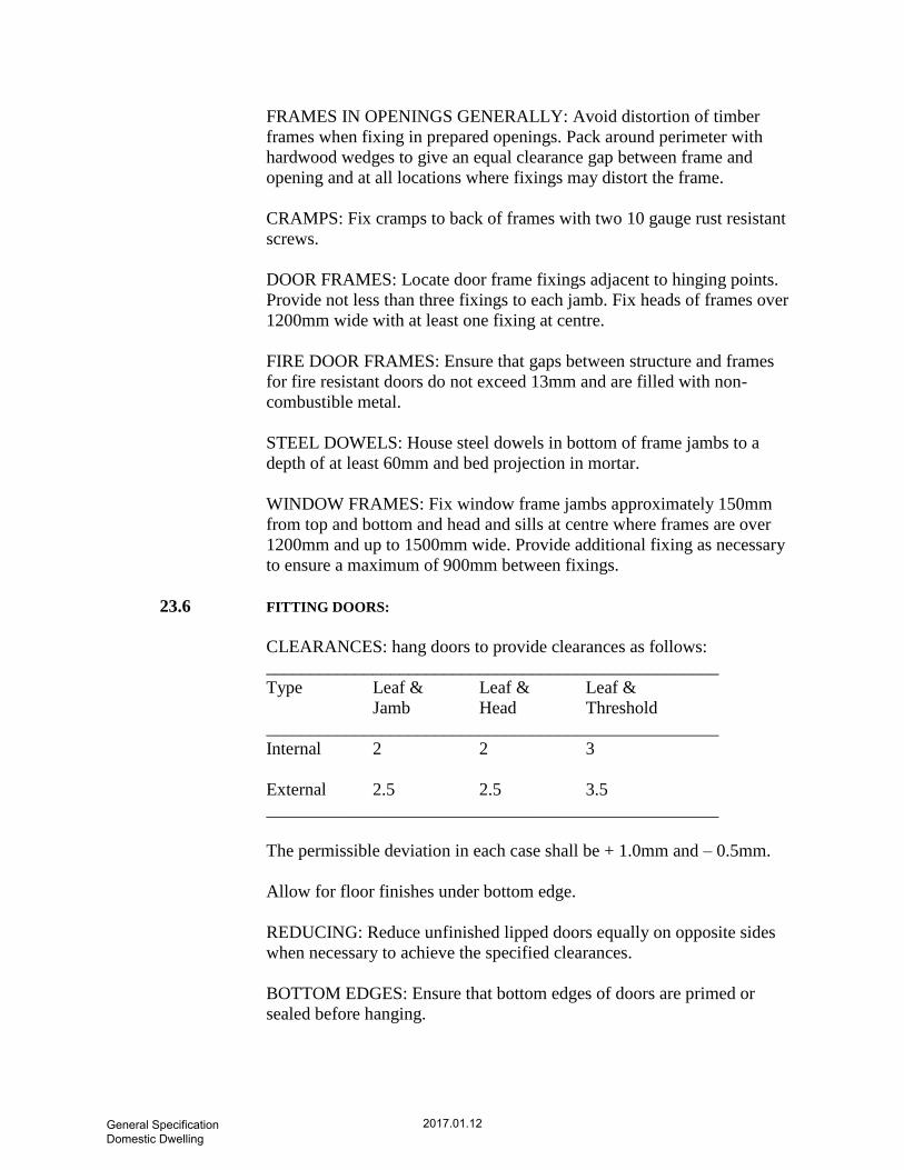
FRAMES IN OPENINGS GENERALLY: Avoid distortion of timber
frames when fixing in prepared openings. Pack around perimeter with
hardwood wedges to give an equal clearance gap between frame and
opening and at all locations where fixings may distort the frame.
CRAMPS: Fix cramps to back of frames with two 10 gauge rust resistant
screws.
DOOR FRAMES: Locate door frame fixings adjacent to hinging points.
Provide not less than three fixings to each jamb. Fix heads of frames over
1200mm wide with at least one fixing at centre.
FIRE DOOR FRAMES: Ensure that gaps between structure and frames
for fire resistant doors do not exceed 13mm and are filled with non-
combustible metal.
STEEL DOWELS: House steel dowels in bottom of frame jambs to a
depth of at least 60mm and bed projection in mortar.
WINDOW FRAMES: Fix window frame jambs approximately 150mm
from top and bottom and head and sills at centre where frames are over
1200mm and up to 1500mm wide. Provide additional fixing as necessary
to ensure a maximum of 900mm between fixings.
23.6 FITTING DOORS:
CLEARANCES: hang doors to provide clearances as follows:
___________________________________________________
Type Leaf & Leaf & Leaf &
Jamb Head Threshold
___________________________________________________
Internal 2 2 3
External 2.5 2.5 3.5
___________________________________________________
The permissible deviation in each case shall be + 1.0mm and – 0.5mm.
Allow for floor finishes under bottom edge.
REDUCING: Reduce unfinished lipped doors equally on opposite sides
when necessary to achieve the specified clearances.
BOTTOM EDGES: Ensure that bottom edges of doors are primed or
sealed before hanging.
General Specification Domestic Dwelling
2017.01.12

HARDWARE INSTALATION: Fix hardware in accordance with the
written instructions. Use screws and fastenings of matching metal and
finish where possible. Use satin chrome plated brass screws with
aluminum hardware, unless otherwise specified and approved.
STRIKING PLATES: Set striking plates flush with adjoining surfaces and
position to allow for dropping of door.
COMPLETION: On completion of works, check all doors and windows
including hardware, to ensure correct functioning and adjust as required.
24.0 ELECTRICITY AND PUBLIC LIGHTENING
24.1 General Contract and Conditions:
CONDITIONS AND WORKMANSHIP: The electrical installation shall
form part of the general building contract and the responsibility for
carrying out the work to a satisfactory conclusion shall be borne by the
Building Contractor who shall, however, sublet the work to an
experienced firm of Electrical Contractors.
Electrical Sub-Contractor to be employed by the General Contractor and
of the arrangements made by the Contractor for carrying out of the work
must be obtained by the General Contractor before the installation is
commenced. Only electrical contractors of good standing and with
previous experience in work of a similar nature will be permitted to
undertake the Electrical Installation.
All electrical work must comply with the requirements of the Engineer
and with the “National Rules for Electrical Installations” (1976), published
by the “Electro Technical Council of Ireland”.
24.2 Workmanship and Supervision:
He must be empowered to settle any minor details that may arise in the
wiring of the project and to carry out alterations or instructions so far as
these instructions are contained in the terms of the specifications,
schedules and plans which shall be deemed to have been accepted in their
entirety by the Contractor, except in the case of any departure therefrom.
24.3 Flexible Cords:
All flexible supporting C.G. holders shall be twin heat resistant PVC
insulated, white PVC sheathed flex to B.S. 6004:200 electric cables, uPVC
insulation amounts cables for voltage up to velocity 450/750 V for electric
General Specification Domestic Dwelling
2017.01.12

power, lights and internal wiring, of best quality and not less than
0.75sq.mm section.
24.4 Socket Outlets:
All socket outlets shall be white flush mounting shuttered three pin 13A
type conforming to B.S. 1363-1-4:1995 sockets.
Double sockets shall consist of two single sockets mounted on a two gang
box which shall have a central pillar designed for this purpose. Socket
outlets in the kitchen shall be switched. Socket outlets in the kitchen shall
be mounted 1.2m above floor level and in all other rooms shall be
mounted 0.3 above floor level. Sockets shall be secured by cup-head
chrome plated screws.
24.5 Light Switches:
Light switches shall be flush type rocker arm 5A switches, switches shall
be fitted 1.2m from floor level and shall be secured with chrome pleated
cup head screws.
24.6 Boxes
Switch and socket outlet boxes shall be standard pattern hard PVC with
brass mounted inserts. They shall finish, flush with the finished wall
surface, using extension collars where necessary.
On walls which are to be dry-lined, or in studding, boxes shall be fixed in
position with two non-corroding woodscrews. On walls which are to be
rendered and skimmed the boxes shall be either by two non-corroding
woodscrews or a hard sand and cement mix. Neither “HILTI” type fixings
nor Masonry nails shall be used in any event. Plaster depth boxes shall not
be used. A standard outlet box with a blank plate shall be provided in the
hot press, below the shelf.
24.7 Earthing:
All socket outlets, control switches and appliances shall be earthed and
neutralized to comply with the most recent “National Rules for Electrical
Installations” published by the Electro-Technical Council of Ireland.
Where the E.C.C. of twin and warth PVC/PVC cable is exposed within a
box it shall be covered by a PVC sleeve.
The canteen and classroom sinks shall be earthed with a separate earth
continuity conductor. All metallic hot, cold and waste pipes shall be
bonded to the sink and to each other. Any gas piping if gas is to be
General Specification Domestic Dwelling
2017.01.12

installed, shall be earthed at the point of entry by a separate 4sq.mm. earth
continuity conductor run unbroken from the neutralizing link.
If an external gas meter box is provided the incoming and outgoing gas
mains shall be bonded together within the meter box in 4sq.mm
green/yellow PVC covered copper E.C.C., sufficient slack shall be left to
enable a gas meter to be installed subsequently without disturbing the
bonding lead. All metalwork, even new copper piping, shall be thoroughly
cleaned and scraped before the bonding clamp is fitted to ensure a good
electrical contact.
The neutralizing ling/earth bar of the consumer unit shall be used in place
of a separate external neutralizing block. It shall be fitted with two double
screw terminals to accept the incoming 6sq.mm main earth lead and the
10sq.mm neutralizing lead to the approval of the Engineer.
The main earth lead shall run from the earth electrode which shall be
galvanized earth rod not less than 12mm diameter, 1.4m long sunk
vertically for its whole length outside the front wall of the school
buildings. Please note that the earth rod shall be not less than 1.4m long.
The connection to the earth electrode shall be made by means of a
nonferrous clamp protected by an approved water-repellent tape and
enclosed in a flush mounted galvanized adaptable box measuring 100mm
x 100mm minimum. The earth lead shall be protected by 12.5mm
‘Hydrodare’ tubing shall enter the box protecting the earth clamp by at
least 5mm.
24.8 Cables:
All cables shall be to B.S. 6004. All cables are to be standard copper. The
sizes of cables to be installed are as follows:
Conductor Size Cable Type Use
1.5sq.mm Single core PVC/PVC Lighting Circuits
2.5sq.mm Twin PVC/PVC with ECC All socket outlets
including ring main.
Immersion group.
2.5sq.mm Single Core Green/ All Earthing and Yellow
PVC Bonding including
lighting points
except where a
larger size is
General Specification Domestic Dwelling
2017.01.12

specified.
4sq.mm Single Core Green/ Bonding of Gas
Yellow PVC Piping.
6sq.mm Twin PVC/PVC with Cooker Circuit
E.C.C.
6sq.mm Single Core Green/ Main Earth Lead
Yellow PVC
10sq.mm Single Core PVC/PVC Tails from meter
housing to fuse
board.
24.9 Conduit:
20mm diameter round PVC conduit shall be installed for switch and
socket drops. The conduit shall be enter each box for at least 5mm and
shall extend at least 100mm into the ceiling cavity. In walls which are
chased to receive it the conduit shall be secured to the satisfaction of the
Engineer, with a hard sand and cement mix to within 6mm of the finished
plaster. On walls which are to be dry-lined the conduit shall be secured by
means of crampets or saddles, spaced in accordance with E.T.C.I.
regulations. Wiring shall not be drawn into conduit until the plastering is
complete.
25mm “Oval” PVC conduit may be used, but only on block walls 75mm
thickness or less which do not allow for chasing and only into boxes
which are to the approval of the Engineer. The use of oval conduit will in
each case be subject to the approval of the Engineer.
25.0 PERFORMANCE SPECIFICATION:
25.1 Materials:
SECTIONS: Aluminium alloy window frame sections to BS EN 1202-
2:2001.
COLOUR: Epoxy free, polyester powders, electro-statically applied and
cured (Syntha-Pulvin).
General Specification Domestic Dwelling
2017.01.12

SEALANTS: Two-part polysulphide based, chemically curing sealant to
comply with current standards. Sealant to be compatible with materials
that are to be sealed.
FIXINGS: All screws visible when windows are closed to be non-
magnetic stainless steel. Other screws may be zinc plated or hot dip
galvanized.
FACIA: 2mm thick pressing as dimensioned; jointed as described.
GLASS: Standard double glazed units (4mm outer leaf, 10mm gap, 4mm
inner leaf) to be low e soft coated with an elemental U-Value of 1.6
W/m²K or better.
PANELS: 2mm thick aluminium pressings ‘glazed’ into window frame
sections.
25.2 Windows:
EXPOSURE: Windows to be resistant to deformation and to penetration
by air and water when tested in accordance with the method described in
BS 4315-2:1970 method of testing for resistance to air and water
penetration, penetrate wall construction (water penetration).
NB Grade of exposure: Severe (a)
___________________________
Maximum 3 sec. Gust: 46/m/s
Wind loadings: 2.0/KNm2
RESISTANCE: To water infiltration: there shall be no gross water leakage
when tested at 40mm water gauge in accordance with BS 4315-2:1970
method of testing for resistance to air and water penetration, penetrate wall
construction (water penetration).
DEFLECTION: Maximum deflection of any member shall not exceed
1/175 of its span and when the load is removed there shall be no evidence
of any permanent deformation or damage to any member when tested for a
period of 15 minutes.
CONSTRUCTION: Couplings, if necessary, to be located to the approval
of the Architect. Junctions to be formed with aluminum inserts with frame
crimped or other method approved by the Architect.
OPENING: Hung, projecting type, friction side stays capable of being
cleaned through gap.
General Specification Domestic Dwelling
2017.01.12
(1) All opening sections to be draught proofed.
(2) Submit drawing showing proposed typical window sections.
IRONMONGERY: To be vandal resistant, heavy duty stainless steel.
IRONMONGERY: To be securely fixed to frame so that there is no
distortion to aluminum section when operated.
GLAZING: To be done from outside in accordance with BS CP 152.
TOLERANCES: Frames shall be square, free from twist fabricated to
tolerances of +/- 1mm.
CLEANING: Remove all burrs and sharp arrises which would be visible
after fixing or a hazard to user.
BONDING:
1. Prepare where applicable surfaces of metals to receive adhesives by
degreasing mechanically or chemically.
2. Use adhesives in accordance with manufacturer’s recommendations.
3. Form bond under pressure.
MITRED JOINTS: To be drawn together with rivet closed to completely
fill holes.
MECHANICAL JOINTS: To be tight with no visible gaps. Connect cleats
to frame where applicable with countersunk machine screws where:
1. Screwheads will be visible after component is fixed.
2. Raised screwheads would interfere with any moving part of
components.
SIZES: All ope sizes to be checked on site before fabrication commences.
DELIVERY: Do not deliver to site, any components which cannot be
unloaded into suitable conditions of storage.
PROTECTION:
1. Avoid distortion of components during transit, handling and storage.
2. Prevent prefinished surfaces from rubbing together.
General Specification Domestic Dwelling
2017.01.12

3. Prevent contact with mud, ashes, plaster and cement.
4. Retain protective coverings in position.
Keep Paper and Cardboard wrappings on aluminum components dry.
25.3 Fixing:
WEATHERTIGHT: All glazing to be wind and water tight on completion.
EDGE CLEARANCE: To be equal all round each pane and not less than
3mm.
SETTING AND LOCATION BLOCKS: Locate as in CP 152 figure.
DISTANCE PIECES: Use in all external bead fixing, to give beds of not
less than 3mm on each side of glass or panel.
25.4 Protection and Cleaning of Finished Work:
CLEANING: Remove all smears and excess compound from sealant.
Leave clean inside and out and free from scratching. Remove all mortar,
plaster or concrete spillage while wet.
25.5 Doors:
DOORS: Heavy duty aluminum sections, framed glazed doors draught
proofed on all sides, stainless steel panel bolt linked to alarm system.
ACTION: Outward opening, complete with floor springs (Dom type or
similar approved).
GLASS: Standard double glazed units.
26.0 FABRICATION GENERALLY:
PROTECTION:During fabrication protect all surfaces which will be
visible in completed work.
COLD FORM WORK: To be free from warping, buckling and fractures.
From bends with a brake press or by cold rolling.
General Specification Domestic Dwelling
2017.01.12

CORNERS: Unless specified otherwise, miter junctions identical sections.
Wood screws to BS 1210:1963specification for wood screws.
Bolts screws and nuts to BS1769:1951 specification unified black
hexagonal bolts, screws, nuts, BS4190:2001 isometric black hexagonal
bolts, screws and nuts.
Washers to BS 3410:1961 specification for metal washers for general
engineering purposes.
Machine screws and nuts to BS 1981:1991 specification for unified
machine screws and machine screw nuts.
Self tapping screws to BS 4174:1972 specification for self tapping screw
and metallic drive screws.
26.1 Preparation and Fixing:
LOADING: Frames must not carry any structural loads.
OPENING: Keep closed and secured during all operations until fixed.
Retain any clamping devices in position.
PLACING: Position and maintain frames and linings plumb level and
square.
DAMP PROOF COURSES: Avoid any displacement of damp proof
courses and ensure that they are positioned correctly to frame.
COMPOSITE ASSEMBLIES: Bed mating surfaces of all metal joints in
mastic.
LUGS: Pack out with shims at point of fixing when necessary.
BUILDING IN: Support and brace frames as necessary to prevent
distortion during erection of adjacent structure.
SEALING JOINTS: Ensure that joints are dry and free from frost.
Remove all loose material, dust and grease.
PREPARE: Joints in accordance with sealant manufacturers
recommendations using solvents and primers where necessary.
MASK : Adjoining surfaces.
INSERT: Backing strips in all joints to be pointed with sealant.
General Specification Domestic Dwelling
2017.01.12

FILL: Joint cavity with sealant in accordance with manufacturer’s
recommendations.
TOOL: Sealant to form a smooth flat bed.
REMOVE: Excess sealant from adjoining surfaces, using clean materials
recommended by sealant manufacturer’s and leave clean.
GLAZING: All glass to be of accurate size with clean undamaged edges
and surfaces which are not disfigured.
KEEP: Glass dry and clean during deliver and storage.
BEADS GASKETS AND GLAZING COMPONENTS: Shall be of
materials which do not react with aluminum finishes, glass or other
glazing materials. Glazing components should not be ordered before
Architects approval of color has been obtained.
ALL: Rebates and grooves to be clean, dry and unobstructed at time of
priming, sealing and glazing.
Metal surrounds – follow recommendation of compound manufacturer and
surround manufacturer in –
1. Ensuring that, if required, a suitable primer has been applied.
2. Preparing surround and beads.
27.0 MATERIAL SPECIFICATION SUMMARY:
27.1 Blockwork:
Blocks:
(a) 215 x 100 solid concrete blocks to external walls and internal wall to be
laid on the flat or vertically where shown on school plan .
(b) 215 x 215 hollow concrete blocks to be used for external front entrance
wall above ground level. Any wall construction that is retaining earth
behind is to be 215 x 100 solid block construction.
General Specification Domestic Dwelling
2017.01.12

Cavity Insulation:
(a) 80mm high density rigid insulation EPS board (Conductivity = 0.023
W/mK) to be installed in the proposed dwelling.
(b) 100mm high density platinum bead insulation (Conductivity = 0.033
W/mK) pumped into the cavity and 50mm EPS high density insulated
plasterboard edge sealed and mushroom fixed to inside surface of external
walls to be installed in the proposed dwelling.
Metal Ties:
Vertical twist stainless steel type 225 x 19 x 3.2mm
Cills:
305mm x 165mm smooth faced, stooled concrete cills with 100mm
bearing at jambs for proposed dwelling.
Lintels:
65mm prestressed concrete lintels to door and steel-lite and concrete
lintels where necessary for window opes of proposed dwelling.
Damp Prrof Courses:
Polythene damp proof courses.
Control Joint Fillers:
12mm Flexcell (type)
joint filler or similar approved product.
Cover Strips:
Patent metal control joint covers.
‘Expament’ type or similar approved.
27.2 Carpentry and Joinery:
Internal Door Frames:
125 x 38mm h.w. framing to concrete block internal partitions.
100 x 38mm h.w. frames to stud partitions. 38 x 12mm planted
stops throughout/fanlights to be included to all doors at ground level.
External Door Frames:
General Specification Domestic Dwelling
2017.01.12

125 x 63 h.w. rebated door frames in the proposed dwelling
Internal Door Leaf:
2.100 x 0.850 x 0.051mm flush type doors with hardwood strips.
External Door Leaf:
See window / door schedule for external door dimensions.
Trapdoor:
750 x 600 x 19mm block board trap door detail.
Architraves:
Ex 44 x 20mm s.w. architrave.
Windows:
Aluminum type synta pulvin or similar approved double glazed units
throughout proposed dwelling.
Window Boards:
Ex 150 x 32mm s.w. cill boards.
Saddles:
Ex 125 (100) x 32mm h.w. saddles where shown on the floor plans.
27.3 Plastering:
Internal Blockwork:
2mm ‘Gyplite’ finish coat on insulated plasterboards in the proposed
dwelling.
Ground Floor Ceiling:
9.5mm Gyplath plasterboard with 5mm Gypweld plaster finish.
General Specification Domestic Dwelling
2017.01.12

External Walls:
(a) 2 COAT, 20mm (spatterdash/undercoat/finish coat). Wood
float finish where shown on elevations.
(b) 2 coat, 12mm wood float finish to plinth.
(c) Wet dash finish where shown on elevations
with max. 6mm pebble aggregate.
27.4 Ironmongery:
Locks and Furniture:
Door furniture, window furniture to be ‘Basta’ type or similar approved.
For detailed specification, see door and window schedule.
(a) Hinges/External Doors:
1 ½ pairs x 125mm brass butt hinges for any wood doors.
(b) Hinges/Internal Doors:
1 ½ pairs x 100mm steel butt hinges.
(c) Hinges/Windows:
1 ½ pairs x cranked steel butt hinges as per window manufactures
specification and Window Restrictors to be fitted on all low level opening
windows throughout the proposed dwelling.
General Specification Domestic Dwelling
2017.01.12


