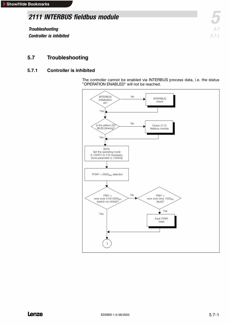
Contents 5 2111 INTERBUS fieldbus module 5.1 L 5.1-1 EDSIBS-1.0-06/2003 5 2111 INTERBUS fieldbus module 5.1 Contents 5.2 General information 5.2-1 ........................................................ 5.3 Technical data 5.3-1 ............................................................ 5.3.1 General data and application conditions 5.3-1 ................................ 5.3.2 Rated data 5.3-1 ..................................................... 5.3.3 Protocol data 5.3-1 ................................................... 5.3.4 Communication times 5.3-2 ............................................. 5.3.5 Dimensions 5.3-4 ..................................................... 5.4 Installation 5.4-1 .............................................................. 5.4.1 Components of the fieldbus module 5.4-1 ................................... 5.4.2 Mechanical installation 5.4-2 ............................................ 5.4.3 Electrical installation 5.4-3 ............................................. 5.5 Commissioning 5.5-1 ........................................................... 5.5.1 Before switching on 5.5-1 ............................................... 5.5.2 Configuration of the INTERBUS master for communication with the fieldbus module 5.5-1 5.5.3 Start up of the 2111 fieldbus module 5.5-2 .................................. 5.5.4 Prepare controller for INTERBUS operation 5.5-3 .............................. 5.5.5 Controller enable via DRIVECOM 5.5-4 ..................................... 5.5.6 DRIVECOM compatibility 5.5-5 ........................................... 5.5.7 Special features when using 82XX, 8200 vector and 93XX 5.5-6 .................. 5.6 Data transfer 5.6-1 ............................................................. 5.6.1 Process data channel configuration 5.6-3 ................................... 5.6.2 Process data signals of Lenze controllers 5.6-7 ............................... 5.6.3 Process data preconfiguration depending on L-C0009 5.6-24 ...................... 5.6.4 Examples for the configuration of PI/PO data 5.6-26 ............................ 5.6.5 Device control 5.6-28 .................................................. 5.6.6 DRIVECOM control 5.6-30 ................................................ 5.6.7 DRIVECOM profile parameters 5.6-33 ....................................... 5.6.8 Configuration of the parameter data channel (PCP communication) 5.6-47 ............ 5.7 Troubleshooting 5.7-1 ........................................................... 5.7.1 Controller is inhibited 5.7-1 ............................................. 5.7.2 Check INTERBUS 5.7-3 ................................................. 5.7.3 Reset error (TRIP) 5.7-4 ................................................ 5.7.4 DRIVECOM error codes 5.7-5 ............................................ 5.8 Appendix 5.8-1 ............................................................... 5.8.1 Code table 5.8-1 ...................................................... 5.9 Index 5.9-1 ..................................................................
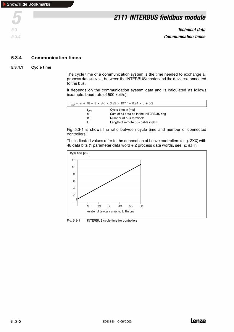
The cycle time of a communication system is the time needed to exchange allprocess data ( 5.6-6) between the INTERBUS master and the devices connectedto the bus.
It depends on the communication system data and is calculated as follows(example: baud rate of 500 kbit/s):
íÅóÅä = Eå+ QU+ P× _hF× PKPR× NM−P+ MKOQ× i+ MKO
tcycl Cycle time in [ms]n Sum of all data bit in the INTERBUS ringBT Number of bus terminalsL Length of remote bus cable in [km]
Fig. 5.3-1 is shows the ratio between cycle time and number of connectedcontrollers.
The indicated values refer to the connection of Lenze controllers (e. g. 2XX) with48 data bits (1 parameter data word + 2 process data words, see ( 5.3-1).
NO
NM
U
S
Q
O
NM OM PM QM RM SM
Cycle time [ms]
Number of devices connected to the bus
N
Fig. 5.3-1 INTERBUS cycle time for controllers
Technical dataCommunication times
52111 INTERBUS fieldbus module
5.35.3.4
L 5.3-3EDSIBS-1.0-06/2003
5.3.4.2 Processing time in the controller
The processing time of the controller is added to the INTERBUS cycle time.
The processing time of the controller depends on the series and version:
For the 820X series several processing steps are required. These steps areprocessed cyclically.
A processing cycle consists of:
Writing of control word or setpoint, if the value has changed
Alternating reading of status word and actual value
Processing of PCP parameter access, if there is a service.
Note!A change of the setpoint signal results in writing the control word.
If the time tolerances caused by cyclic reading of the status word/actual value aretoo large, the alternating reading of the status word and the actual value can besuppressed. This is controlled by bit 15 (PE inhibit) of the DRIVECOM controlword: ( 5.6-35).
A suppression of the processing of parameter access is not necessary, since thisis controlled by the user.
In the following table you will find a list of the processing times:
Processing step Max. processing time[ms]
Processing tolerance[ms]
Additional parameter[ms]
Parameter 70 -8 -Setpoint 35 -8 180Control word 35 -8 180Actual value 35 -8 180Status word 35 -8 180Setpoint + control word 70 -16 180Setpoint + control word + actualvalue + status word
140 -32 180
The parameter data (transmission via PCP channel) and process data areindependent of each other.
Parameter data (PCP): approx. 30 ms + 20 ms tolerance
Process data (PD): approx. 3 ms + 2 ms tolerance
The parameter data (transmission via PCP channel) and process data areindependent of each other.
Parameter data (PCP): approx. 30 ms + 20 ms tolerance
Process data (PD): approx. 2 ms + 1 ms tolerance
Parameter data (PCP): 30 ms + 20 ms tolerance
Process data (PD): depending on process image
Processing time 820X
Processing time 821X /8200 vector / 822X
Processing time 9300 servoinverter
Processing time Drive PLC / 9300Servo PLC
Technical dataDimensions
5 2111 INTERBUS fieldbus module
5.35.3.5
L5.3-4 EDSIBS-1.0-06/2003
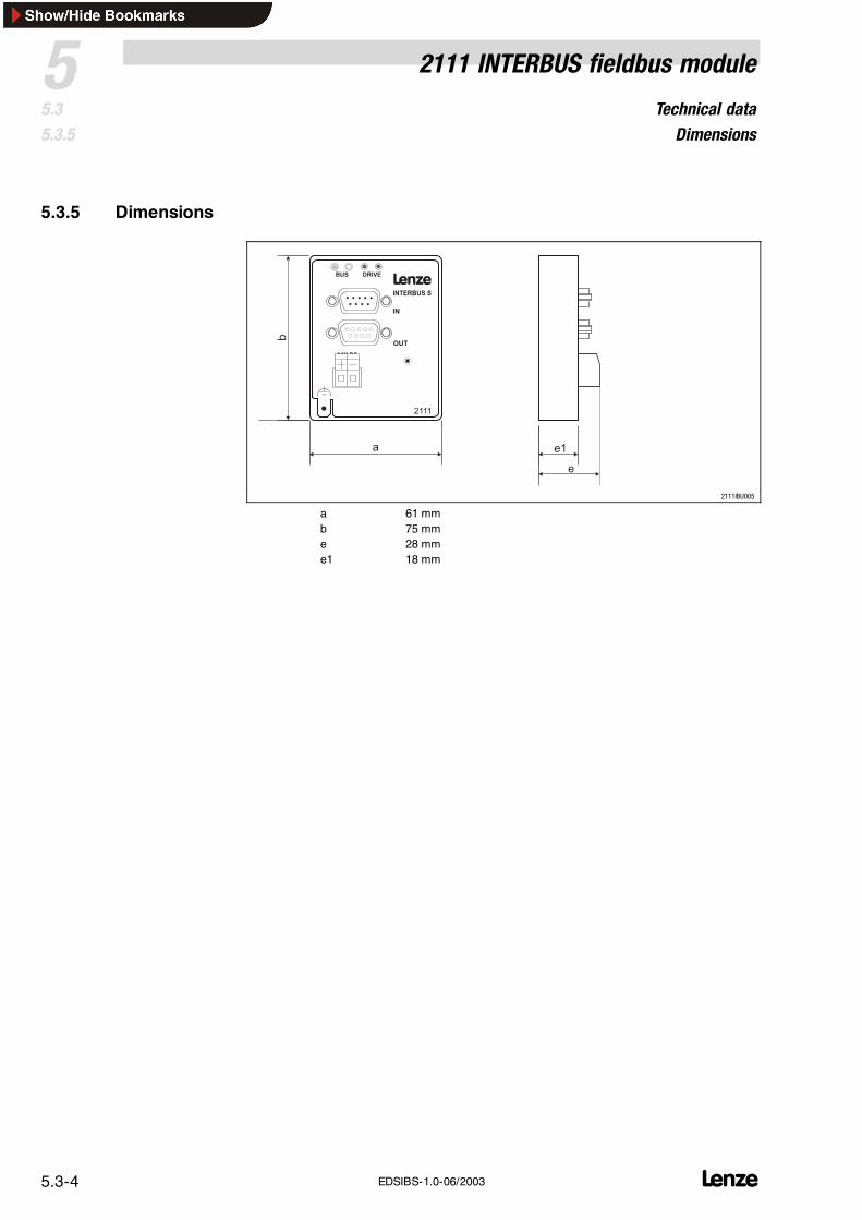
5.3.5 Dimensions
18
INTERBUS S
2111
LBUS
OUT
IN
24V DC+ _
DRIVE
a
b
e1
e
2111IBU005
a 61 mmb 75 mme 28 mme1 18 mm
InstallationComponents of the fieldbus module
52111 INTERBUS fieldbus module
5.45.4.1
L 5.4-1EDSIBS-1.0-06/2003
5.4 Installation
5.4.1 Components of the fieldbus module
INTERBUS S
2111
LBUS
OUT
IN
24V DC+ _
DRIVE
2111IBU004
Fig. 5.4-1 Components of the fieldbus module
Pos LED status Explanation 3
Green bus LED (voltage supply)
ON The fieldbus module is supplied with voltage and is connected to the drive controller.
OFF The fieldbus module is not supplied with voltage. The drive controller or externalvoltage supply is switched off.
BLINKING The fieldbus module is supplied with voltage, but it is not connected to the drivecontroller, because• the fieldbus module was not plugged on the drive controller correctly• the data transfer of/to the drive controller is not possible (e. g. the drive controller
is in the initialisation phase).
Yellow bus LED (communication)
ON Fieldbus module is initialised,inactive INTERBUS communication of the master
OFF Fieldbus module is not initialised yet
BLINKING Active INTERBUS communication• SLOW (1 Hz): process data and PCP communication.• FAST (4 Hz): only process data
Red and green drive LED indicate the operating mode of the drive controller 82XX or 93XX (see theOperating Instructions of the drive controller)
Plug connector, connection for external voltage supply 5.4-5
PE connection see note
Fixing screw
Note!Only for 820X and 821X: If required use an additional PE screencable which avoids EMC-related communication interference insurroundings with interferences.
InstallationMechanical installation
5 2111 INTERBUS fieldbus module
5.45.4.2
L5.4-2 EDSIBS-1.0-06/2003
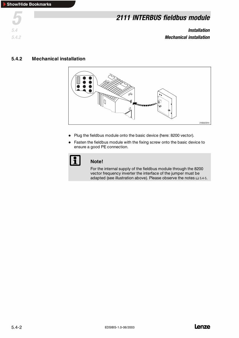
5.4.2 Mechanical installation
4 2102LEC014
Plug the fieldbus module onto the basic device (here: 8200 vector).
Fasten the fieldbus module with the fixing screw onto the basic device toensure a good PE connection.
Note!For the internal supply of the fieldbus module through the 8200vector frequency inverter the interface of the jumper must beadapted (see illustration above). Please observe the notes 5.4-5.
InstallationElectrical installation
52111 INTERBUS fieldbus module
5.45.4.3
L 5.4-3EDSIBS-1.0-06/2003
5.4.3 Electrical installation
Note!An additional mains isolation is required, if a 820X or 821X is connected to an INTERBUS master and a safe mains isolation (double basic insulation) is required
according to VDE 0160.Use e.g. a bus terminal or an interface module for the INTERBUSmaster with an additional mains isolation (see the correspondinginformation of the manufacturer).
The bus system must be designed as a ring.
Go-and-return lines are both in the same bus cable.
The ring connects the INTERBUS master with all devices connected to thebus.
Wiring to the INTERBUS master
InstallationElectrical installation
5 2111 INTERBUS fieldbus module
5.45.4.3
L5.4-4 EDSIBS-1.0-06/2003
4
00
m
400 m
3.1
INTERBUS-Loop 100 m
10 m
82XX
+
2112
8200 vector
+
2111
93XX
+
2111
82XX
+
2111
93XX
+
2112
8200 vector
+
2112
3.1 3.1
3.2
3.23.23.2
4.2
4.2 4.24.2
2
4
4.1 4.14.1
1
3
2111IBU001
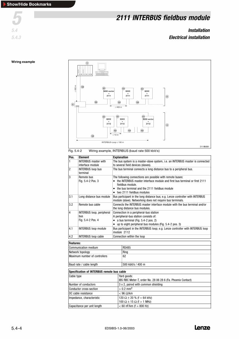
Fig. 5.4-2 Wiring example, INTERBUS (baud rate 500 kbit/s)
Pos. Element Explanation1 INTERBUS master with
interface moduleThe bus system is a master-slave system, i.e. an INTERBUS master is connectedto several field devices (slaves).
2 INTERBUS loop busterminal
The bus terminal connects a long distance bus to a peripheral bus.
3 Remote busFig. 5.4-2 Pos. 3
The following connections are possible with remote buses:• the INTERBUS master interface module and first bus terminal or first 2111
fieldbus module.• the bus terminal and the 2111 fieldbus module• two 2111 fieldbus modules
3.1 Long distance bus module Bus participant in the long distance bus; e.g. Lenze controller with INTERBUSmodule (slave). Networking does not require bus terminals.
3.2 Remote bus cable Connects the INTERBUS master interface module with the bus terminal and/orthe long distance bus modules.
4 INTERBUS loop, peripheralbusFig. 5.4-2 Pos. 4
Connection in a peripheral-bus stationA peripheral-bus station consists of:• a bus terminal (Fig. 5.4-2 pos. 2)• up to eight peripheral bus modules (Fig. 5.4-2 pos. 3)
4.1 INTERBUS loop module Bus participant in the INTERBUS loop; e.g. Lenze controller with INTERBUS loopmodule 2112
4.2 INTERBUS loop cable Connection within the loop
Features:Communication medium RS485Network topology RingMaximum number of controllers 62
Baud rate / cable length 500 kbit/s / 400 m
Specification of INTERBUS remote bus cable 5Cable type Yard goods:
IBS RBC Meter-T, order No. 28 06 28 6 (Fa. Phoenix Contact)Number of conductors 3 x 2, paired with common shieldingConductor cross-section > 0.2 mm2
Tightening torque 0.5 ... 0.6 Nm (4.4 ... 5.3 lb-in)Bare end 6 mm
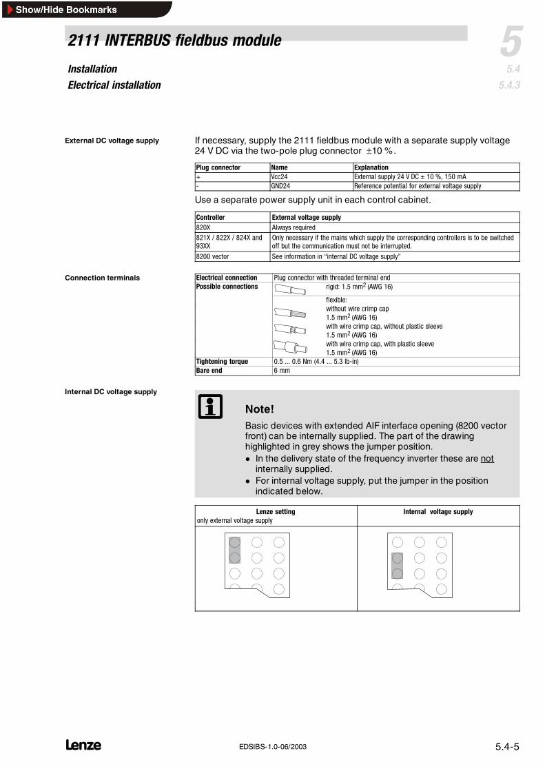
Note!Basic devices with extended AIF interface opening (8200 vectorfront) can be internally supplied. The part of the drawinghighlighted in grey shows the jumper position. In the delivery state of the frequency inverter these are not
internally supplied. For internal voltage supply, put the jumper in the position
indicated below.
Lenze settingonly external voltage supply
Internal voltage supply
External DC voltage supply 6
Connection terminals 7
Internal DC voltage supply 8
InstallationElectrical installation
5 2111 INTERBUS fieldbus module
5.45.4.3
L5.4-6 EDSIBS-1.0-06/2003
5.4.3.1 Connection from the INTERBUS
2111
LINTERBUS S
BUSDRIVE
24V DC
_+
OUT
IN
2111IBU006
IN
1
6
5
9
2113IBU012
Sub-D pin connector (IN)Pin Name Input/output Explanation1 DO1 Input RS485: DO1 not inverted2 DI1 Output RS485: DI1 not inverted3 GND Reference potential4 free5 Vcc5 5 V DC6 /DO1 Input RS485: DO1 inverted7 /DI1 Output RS485: DI1 inverted8 Vcc5 5 V DC9 free
Tab. 5.4-1 Pin assignment of the Sub-D pin connector (IN)
InstallationElectrical installation
52111 INTERBUS fieldbus module
5.45.4.3
L 5.4-7EDSIBS-1.0-06/2003
5.4.3.2 Connection to the INTERBUS
PC
2111
LINTERBUS S
BUSDRIVE
24V DC
_+
OUT
IN
2111IBU006
OUT
1
6
5
9
2113IBU011
Sub-D socket connector (OUT)Pin Name Input/output Explanation1 DO2 Output RS485: DO2 not inverted2 DI2 Input RS485: DI2 not inverted3
GND Reference potential4
GND Reference potential
5 Vcc5 Output 5 V DC6 /DO2 Output RS485: DO2 inverted7 /DI2 Input RS485: DI2 inverted8 Vcc5 5 V DC9 RBST Message input The assignment of the Sub-D socket connector
(OUT) with a Sub-D plug is indicated.
Tab. 5.4-2 Pin assignment of the Sub-D socket connector (OUT)
CommissioningBefore switching on
52111 INTERBUS fieldbus module
5.55.5.1
L 5.5-1EDSIBS-1.0-06/2003
5.5 Commissioning
5.5.1 Before switching on
Stop!Before switching on the mains voltage, check the wiring forcompleteness, earth fault and short circuit.
Note!Do not change the switch-on sequence!
5.5.2 Configuration of the INTERBUS master for communication with the fieldbusmodule
The host parameters (PC, PLC, etc.) are typically set via the PC program”SYSSWT” of Phoenix Contact.
For conversion formula and parameter value range see 5.6-46
8200 vector (up to SW version 1.1) C0410/y (y = 1...16) must be assigned to the AIF control word (AIF-CTRL)
i.e. C0410/1 = 10, C0410/2 = 11 .... C0410/16 = 25 (see OperatingInstructions for 8200 vector).
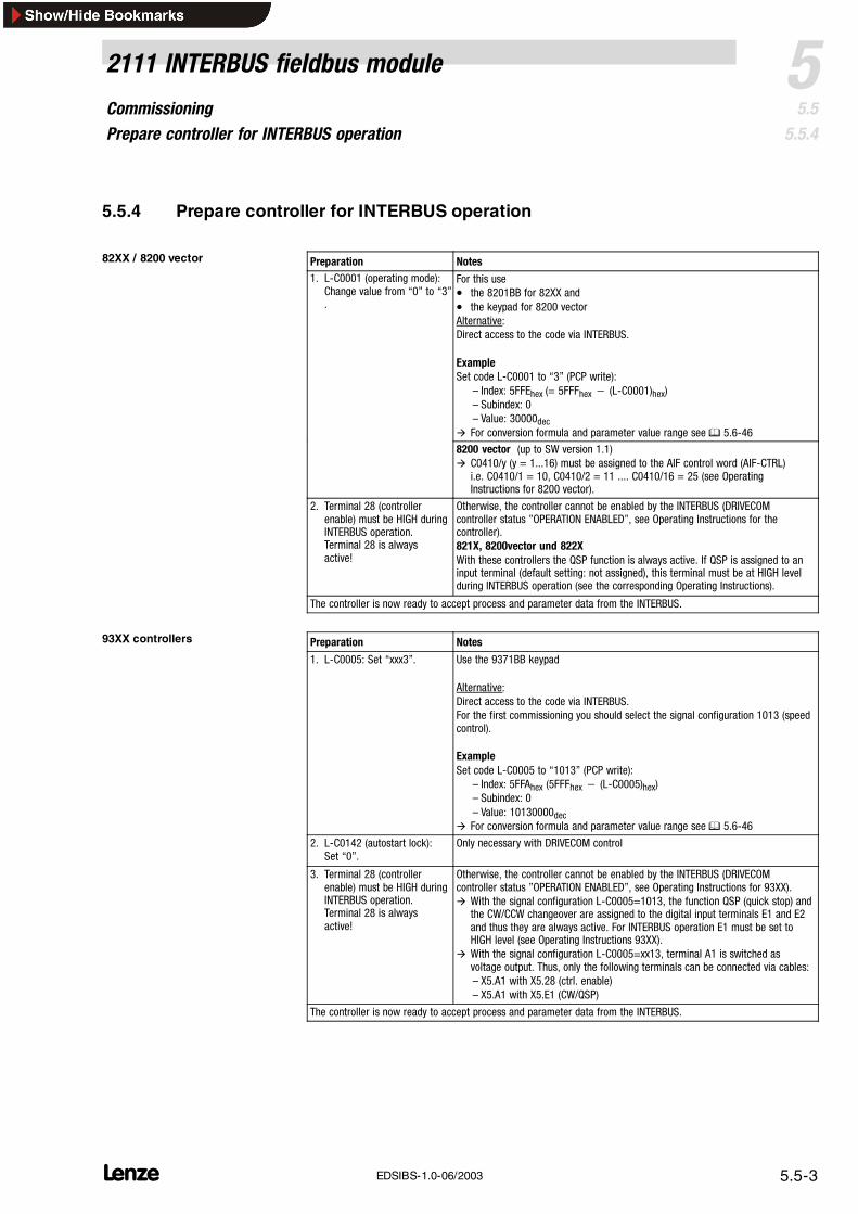
2. Terminal 28 (controllerenable) must be HIGH duringINTERBUS operation.Terminal 28 is alwaysactive!
Otherwise, the controller cannot be enabled by the INTERBUS (DRIVECOMcontroller status ”OPERATION ENABLED”, see Operating Instructions for thecontroller).821X, 8200vector und 822XWith these controllers the QSP function is always active. If QSP is assigned to aninput terminal (default setting: not assigned), this terminal must be at HIGH levelduring INTERBUS operation (see the corresponding Operating Instructions).
The controller is now ready to accept process and parameter data from the INTERBUS.
Preparation Notes
1. L-C0005: Set “xxx3”. Use the 9371BB keypad
Alternative:Direct access to the code via INTERBUS.For the first commissioning you should select the signal configuration 1013 (speedcontrol).
For conversion formula and parameter value range see 5.6-46
2. L-C0142 (autostart lock):Set “0”.
Only necessary with DRIVECOM control
3. Terminal 28 (controllerenable) must be HIGH duringINTERBUS operation.Terminal 28 is alwaysactive!
Otherwise, the controller cannot be enabled by the INTERBUS (DRIVECOMcontroller status ”OPERATION ENABLED”, see Operating Instructions for 93XX). With the signal configuration L-C0005=1013, the function QSP (quick stop) and
the CW/CCW changeover are assigned to the digital input terminals E1 and E2and thus they are always active. For INTERBUS operation E1 must be set toHIGH level (see Operating Instructions 93XX).
With the signal configuration L-C0005=xx13, terminal A1 is switched asvoltage output. Thus, only the following terminals can be connected via cables:– X5.A1 with X5.28 (ctrl. enable)– X5.A1 with X5.E1 (CW/QSP)
The controller is now ready to accept process and parameter data from the INTERBUS.
82XX / 8200 vector
93XX controllers
CommissioningController enable via DRIVECOM
5 2111 INTERBUS fieldbus module
5.55.5.5
L5.5-4 EDSIBS-1.0-06/2003
5.5.5 Controller enable via DRIVECOM
Controllers can be controlled with DRIVECOM process data. The INTERBUSmaster has direct access to the process data. In the INTERBUS master, data arestored in the I/O area.
Controller enable: DRIVECOM process data word ”Control word”
Display of actual controller status: DRIVECOM process data word ”Statusword”.
The controller can be enabled by changing to OPERATION ENABLED by meansof the DRIVECOM control word.
Afterwards, the controller can be controlled as usual, e.g. via terminals.
Note!If DRIVECOM control is active and the fieldbus module in the controller
– 82XX / 8200 vector “controller inhibit” will be activated ifL-C0001 = 3.
– 93XX “Controller inhibit” will always be active. the fieldbus module sets SWITCH ON INHIBIT.
Enable the controller as follows:
1. Select speed setpoint (2nd process data word; PD2), value ≠ 0.
2. Change to ”READY FOR SWITCH ON“PD output word1 = 0000 0000 0111 1110bin (007Ehex).
3. Wait for the status ”READY FOR SWITCH ON“.PD input word1 = xxxx xxxx x01x 0001bin.
The DRIVECOM profile 21 is a specification of important parameters and unitperformance of several manufacturers. The DRIVECOM profile 21 mainlydescribes the unit control and a speed operating mode. In addition to theDRIVECOM specifications there are further Lenze-specific functions, e.g.digital-frequency connection or DC injection-brake. Thesemanufacturer-specificspecifications require minor changes in the settings to comply with the desiredDRIVECOM compatibility. In the following, you will find the changes required forthe Lenze controllers.
820X With 820X controllers, parameters can only be set when the controller is inhibited.The controller is inhibited in DRIVECOM status.• ”SWITCH-ON INHIBIT”• ”READY FOR SWITCH ON”• ”SWITCHED ON”• ”TRIP”
821X,8200 vectorand 822X
The automatic DC-injection brake must be deactivated in all parameter sets, i. e.• L-C0106=0• L-C2106=0• L-C4106=0 (only 8200 vector)• L-C6106=0 (only 8200 vector)If the automatic DC-injection brake is not deactivated (holding time of the DC-injection brake L-C0106not 0), the controller automatically switches from the status ”OPERATION ENABLED” to the status”SWITCHED ON” when the speed is 0 and the holding time of the DC-injection brake is elapsed. If thesetpoint is higher than 0, the controller is automatically reset to the status ”OPERATION ENABLED”.
93XX Set the controller parameters for INTERBUS control, e.g. L-C0005=1013This configuration corresponds to the signal configuration 1000 with the following changes:• Setpoint selection with INTERBUS• Unit control with INTERBUS• Output X5.A1 is selected as voltage output for the internal supply of the digital inputs.• Actual values and status signals for INTERBUSFor the detailed description of the signal configuration, see 93XX Manual.
9300 ServoPLC
The following links must be made in the PLC program.• AIF1_wDctrlCtrl DCTRL_wAIF1Ctrl• DCTRL_wStat AIF1_wDctrlStat
Drive PLC It is necessary to use the device control for the DRIVE PLC.
CommissioningSpecial features when using 82XX, 8200 vector and 93XX
5 2111 INTERBUS fieldbus module
5.55.5.7
L5.5-6 EDSIBS-1.0-06/2003
5.5.7 Special features when using 82XX, 8200 vector and 93XX
Danger!Please note For safe operation it is absolutely necessary to observe the
notes for the controllers given in this chapter. Please observe the corresponding Operating Instructions of the
controllers.
820X • Parameter setting (codes except process data) is only possible when the controller is inhibited(DRIVECOM controller status unequal ”OPERATION ENABLED“). Parameters are accepted when thecontroller is enabled, but they are not saved.
• A TRIP must only be reset through INTERBUS:If the controller is set to the status TRIP while being operated with INTERBUS control(L-C0001 = 3) and if the TRIP is reset through terminal 28, the drive can start for a short time.When resetting a fault via INTERBUS, this does not occur.
• After the command ”TRIP reset“ the 820X controller is basically initialized. During this time thecontroller does not accept any services.
• Always send the direction of rotation with a low setpoint before the new setpoint:If the setpoint and the direction of rotation are changed at the same time via the DRIVECOM speedsetpoint, the speed can change to the wrong direction or rotation for a short time. This is becausethe setpoint is sent to the controller as unipolar value before and the information about thedirection of rotation is sent.
8200 vector • Digital and analog input and output signals can be freely configured (see Operating Instructions for8200 vector; codes L-C0410, L-C0412, L-C0417 and L-C0421)
• A change of code L-C0001 to “3“ preconfigures the process data words in the controller.
93XX • Set the signal configuration L-C0005 = xxx3 instead of the operating mode L-C0001.• The change of the code L-C0005 to xxx3 starts the preconfiguration of the process data words in
the controller• Set the parameter L-C0142 = 0 (auto start lock), to avoid a short time start of the drive during the
initialization phase.
Data transfer
52111 INTERBUS fieldbus module
5.6
L 5.6-1EDSIBS-1.0-06/2003
5.6 Data transfer
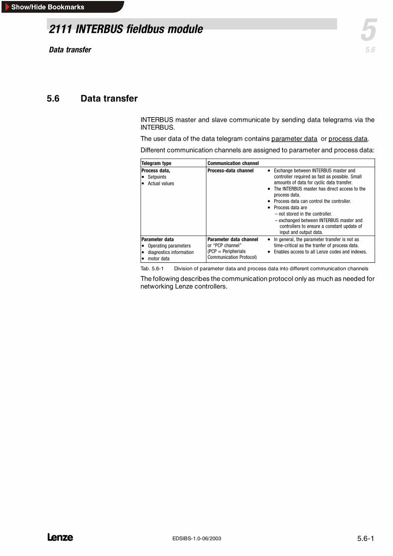
INTERBUS master and slave communicate by sending data telegrams via theINTERBUS.
The user data of the data telegram contains parameter data or process data.
Different communication channels are assigned to parameter and process data:
Telegram type Communication channelProcess data,• Setpoints• Actual values
Process-data channel • Exchange between INTERBUS master andcontroller required as fast as possible. Smallamounts of data for cyclic data transfer.
• The INTERBUS master has direct access to theprocess data.
• Process data can control the controller.• Process data are
– not stored in the controller.– exchanged between INTERBUS master andcontrollers to ensure a constant update ofinput and output data.
Parameter data• Operating parameters• diagnostics information• motor data
Parameter data channelor “PCP channel”(PCP = PeripherialsCommunication Protocol)
• In general, the parameter transfer is not astime-critical as the tranfer of process data.
• Enables access to all Lenze codes and indexes.
Tab. 5.6-1 Division of parameter data and process data into different communication channels
The following describes the communication protocol only as much as needed fornetworking Lenze controllers.
Data transferProcess data channel configuration
5 2111 INTERBUS fieldbus module
5.65.6.1
L5.6-2 EDSIBS-1.0-06/2003
5.6.1 Process data channel configuration
5.6.1.1 Process data transfer
Process data telegrams between INTERBUS master and the controllersconnected to the INTERBUS are divided into:
Process data telegrams from drive (PI)
Process data telegrams to drive (PO)
Note!As agreed, the data flow is described from the INTERBUSmaster’s view: PI data of the INTERBUS master are output data for the
controller. PO data of the INTERBUS master are input data for the
controller.
For the cyclic process data telegram from the drive, the function block to be usedis called AIF-OUT. The status word included in the process data telegram (byte1 and byte 2) is sent to the INTERBUS master via this function block.
For the cyclic process data telegram to the drive, the function block to be usedis called AIF-IN. The control word included in the process data telegram (byte 1and byte 2) is sent to the INTERBUS master via this function block.
Process data telegram fromdrive
Process data telegram to drive
Data transferProcess data channel configuration
52111 INTERBUS fieldbus module
5.65.6.1
L 5.6-3EDSIBS-1.0-06/2003
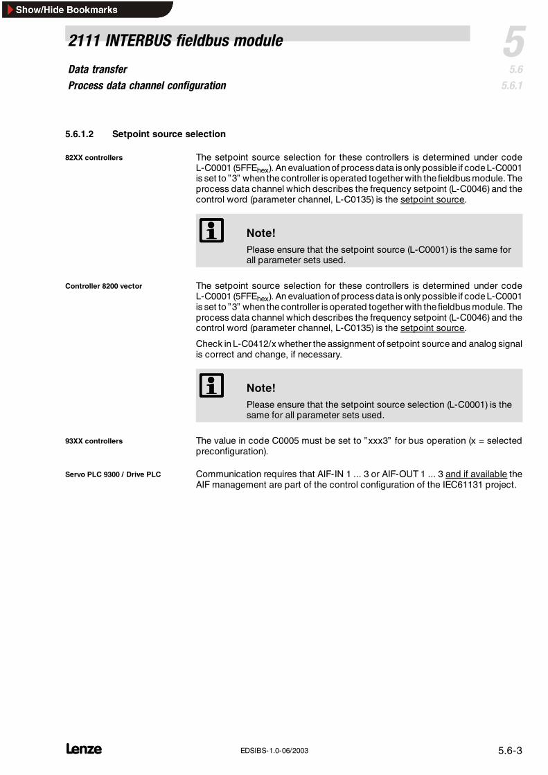
5.6.1.2 Setpoint source selection
The setpoint source selection for these controllers is determined under codeL-C0001 (5FFEhex). An evaluationof process data is only possible if codeL-C0001is set to ”3” when the controller is operated together with the fieldbus module. Theprocess data channel which describes the frequency setpoint (L-C0046) and thecontrol word (parameter channel, L-C0135) is the setpoint source.
Note!Please ensure that the setpoint source (L-C0001) is the same forall parameter sets used.
The setpoint source selection for these controllers is determined under codeL-C0001 (5FFEhex). An evaluationof process data is only possible if codeL-C0001is set to ”3” when the controller is operated together with the fieldbus module. Theprocess data channel which describes the frequency setpoint (L-C0046) and thecontrol word (parameter channel, L-C0135) is the setpoint source.
Check in L-C0412/x whether the assignment of setpoint source and analog signalis correct and change, if necessary.
Note!Please ensure that the setpoint source selection (L-C0001) is thesame for all parameter sets used.
The value in code C0005 must be set to ”xxx3” for bus operation (x = selectedpreconfiguration).
Communication requires that AIF-IN 1 ... 3 or AIF-OUT 1 ... 3 and if available theAIF management are part of the control configuration of the IEC61131 project.
82XX controllers
Controller 8200 vector
93XX controllers
Servo PLC 9300 / Drive PLC
Data transferProcess data channel configuration
5 2111 INTERBUS fieldbus module
5.65.6.1
L5.6-4 EDSIBS-1.0-06/2003
5.6.1.3 Process data configuration
Some data important for the process must be transmitted as quickly as possible.These data are called process data and stored in the I/O area of the controller foraccess from the INTERBUS master.
The process data are cyclically exchanged between the controller and theINTERBUS master.
The process data of a Process-data configuration have a certain ”Process datastructure“.
The process-data structure is subdivided into
Process input data (PI data, index = 6000hex, ( 5.6-5))
Process output data (PO data, index = 6001hex, ( 5.6-5))
The controller receives control information from the INTERBUS master and sendsstatus information to the master.
The Lenze setting for the process-data length is 4 byte.
The PD length is set under code L-C1910.
Note!The assignment of the AIF-CTRL control word to PO data is onlyuseful, if the Drivecom status machine is switched off. This isachieved by entering “0” under L-C1911.Different controller signals can be assigned to the PI and PO datawords (see ( 5.6-6)).
Data transferProcess data channel configuration
52111 INTERBUS fieldbus module
5.65.6.1
L 5.6-5EDSIBS-1.0-06/2003
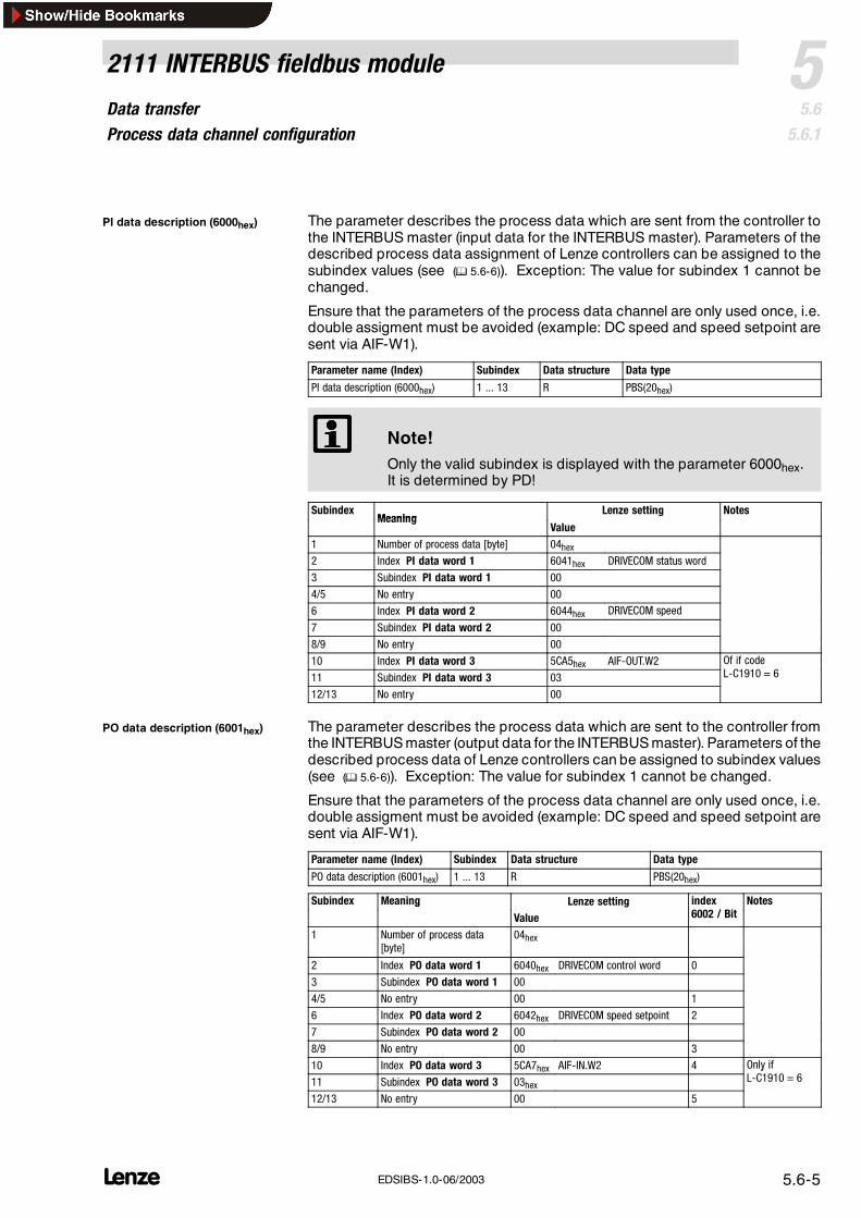
The parameter describes the process data which are sent from the controller tothe INTERBUS master (input data for the INTERBUS master). Parameters of thedescribed process data assignment of Lenze controllers can be assigned to thesubindex values (see ( 5.6-6)). Exception: The value for subindex 1 cannot bechanged.
Ensure that the parameters of the process data channel are only used once, i.e.double assigment must be avoided (example: DC speed and speed setpoint aresent via AIF-W1).
Parameter name (Index) Subindex Data structure Data type
PI data description (6000hex) 1 ... 13 R PBS(20hex)
Note!Only the valid subindex is displayed with the parameter 6000hex.It is determined by PD!
SubindexMeaning
Lenze setting NotesMeaning
Value1 Number of process data [byte] 04hex2 Index PI data word 1 6041hex DRIVECOM status word
3 Subindex PI data word 1 00
4/5 No entry 00
6 Index PI data word 2 6044hex DRIVECOM speed
7 Subindex PI data word 2 00
8/9 No entry 00
10 Index PI data word 3 5CA5hex AIF-OUT.W2 Of if codeC11 Subindex PI data word 3 03 L-C1910 = 6
12/13 No entry 00
The parameter describes the process data which are sent to the controller fromthe INTERBUS master (output data for the INTERBUS master). Parameters of thedescribed process data of Lenze controllers can be assigned to subindex values(see ( 5.6-6)). Exception: The value for subindex 1 cannot be changed.
Ensure that the parameters of the process data channel are only used once, i.e.double assigment must be avoided (example: DC speed and speed setpoint aresent via AIF-W1).
Parameter name (Index) Subindex Data structure Data type
PO data description (6001hex) 1 ... 13 R PBS(20hex)
Subindex Meaning Lenze setting index/
Notesg
Value 6002 / Bit
1 Number of process data[byte]
04hex
2 Index PO data word 1 6040hex DRIVECOM control word 0
3 Subindex PO data word 1 00
4/5 No entry 00 1
6 Index PO data word 2 6042hex DRIVECOM speed setpoint 2
7 Subindex PO data word 2 00
8/9 No entry 00 3
10 Index PO data word 3 5CA7hex AIF-IN.W2 4 Only ifC11 Subindex PO data word 3 03hex
yL-C1910 = 6
12/13 No entry 00 5
PI data description (6000hex)9
PO data description (6001hex)10
Data transferProcess data signals of Lenze controllers
5 2111 INTERBUS fieldbus module
5.65.6.2
L5.6-6 EDSIBS-1.0-06/2003
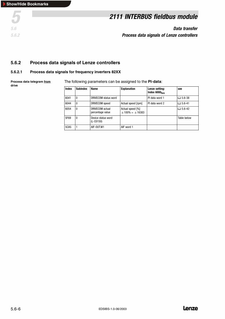
5.6.2 Process data signals of Lenze controllers
5.6.2.1 Process data signals for frequency inverters 82XX
The following parameters can be assigned to the PI-data:
Index Subindex Name Explanation Lenze setting:Index 6000hex
see
6041 0 DRIVECOM status word PI data word 1 5.6-38
6044 0 DRIVECOM speed Actual speed [rpm] PI data word 2 5.6-41
6054 0 DRIVECOM actualpercentage value
Actual speed [%]100% =16383
5.6-42
5F69 0 Device status word(L-C0150)
Table below
5CA5 1 AIF-OUT.W1 AIF word 1
Process data telegram fromdrive
Data transferProcess data signals of Lenze controllers
52111 INTERBUS fieldbus module
5.65.6.2
L 5.6-7EDSIBS-1.0-06/2003
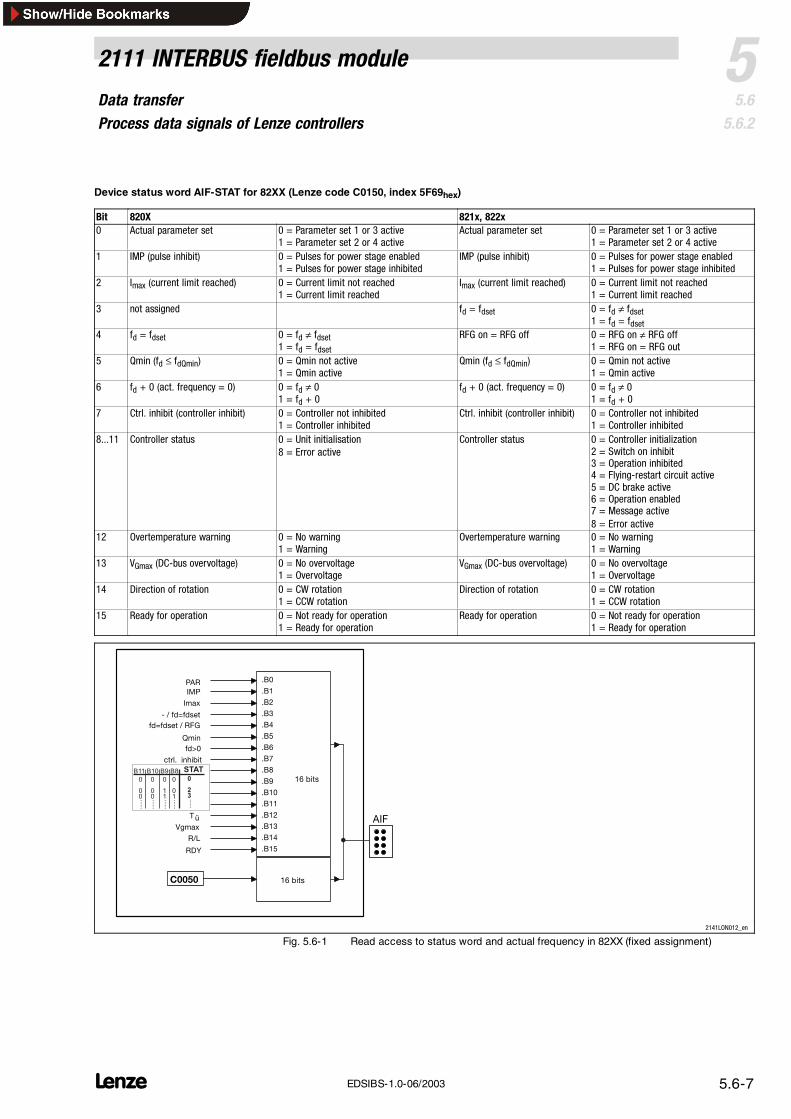
Device status word AIF-STAT for 82XX (Lenze code C0150, index 5F69hex)
Bit 820X 821x, 822x0 Actual parameter set 0 = Parameter set 1 or 3 active
1 = Parameter set 2 or 4 activeActual parameter set 0 = Parameter set 1 or 3 active
1 = Parameter set 2 or 4 active1 IMP (pulse inhibit) 0 = Pulses for power stage enabled
1 = Pulses for power stage inhibitedIMP (pulse inhibit) 0 = Pulses for power stage enabled
1 = Pulses for power stage inhibited2 Imax (current limit reached) 0 = Current limit not reached
1 = Current limit reachedImax (current limit reached) 0 = Current limit not reached
1 = Current limit reached3 not assigned fd = fdset 0 = fd ≠ fdset
1 = fd = fdset4 fd = fdset 0 = fd ≠ fdset
1 = fd = fdsetRFG on = RFG off 0 = RFG on ≠ RFG off
1 = RFG on = RFG out5 Qmin (fd ≤ fdQmin) 0 = Qmin not active
1 = Qmin activeQmin (fd ≤ fdQmin) 0 = Qmin not active
1 = Controller inhibited8...11 Controller status 0 = Unit initialisation
8 = Error activeController status 0 = Controller initialization
2 = Switch on inhibit3 = Operation inhibited4 = Flying-restart circuit active5 = DC brake active6 = Operation enabled7 = Message active8 = Error active
12 Overtemperature warning 0 = No warning1 = Warning
Overtemperature warning 0 = No warning1 = Warning
13 VGmax (DC-bus overvoltage) 0 = No overvoltage1 = Overvoltage
VGmax (DC-bus overvoltage) 0 = No overvoltage1 = Overvoltage
14 Direction of rotation 0 = CW rotation1 = CCW rotation
Direction of rotation 0 = CW rotation1 = CCW rotation
15 Ready for operation 0 = Not ready for operation1 = Ready for operation
Ready for operation 0 = Not ready for operation1 = Ready for operation
16 bits
16 bits
.B15
.B12
.B0
.B1
.B2
.B3
.B4
.B8
.B9
.B10
.B11
.B13
.B14
.B5
.B6
.B7
IMP
fd=fdset / RFG
Qmin
Imax
- / fd=fdset
PAR
fd>0
ctrl. inhibit
Vgmax
R/L
RDY
Tü AIF
C0050
STATB11 B10 B9 B8
0
01......
0
11......
0
00......
0
00......
0
23......
2141LON012_en
Fig. 5.6-1 Read access to status word and actual frequency in 82XX (fixed assignment)
Data transferProcess data signals of Lenze controllers
5 2111 INTERBUS fieldbus module
5.65.6.2
L5.6-8 EDSIBS-1.0-06/2003
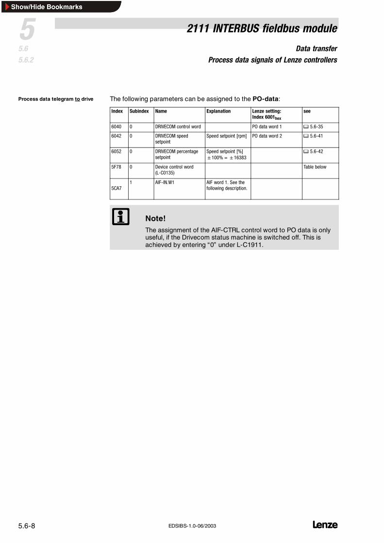
The following parameters can be assigned to the PO-data:
Index Subindex Name Explanation Lenze setting:Index 6001hex
see
6040 0 DRIVECOM control word PO data word 1 5.6-35
6042 0 DRIVECOM speedsetpoint
Speed setpoint [rpm] PO data word 2 5.6-41
6052 0 DRIVECOM percentagesetpoint
Speed setpoint [%]100% =16383
5.6-42
5F78 0 Device control word(L-C0135)
Table below
5CA71 AIF-IN.W1 AIF word 1. See the
following description.
Note!The assignment of the AIF-CTRL control word to PO data is onlyuseful, if the Drivecom status machine is switched off. This isachieved by entering “0” under L-C1911.
Process data telegram to drive
Data transferProcess data signals of Lenze controllers
52111 INTERBUS fieldbus module
5.65.6.2
L 5.6-9EDSIBS-1.0-06/2003
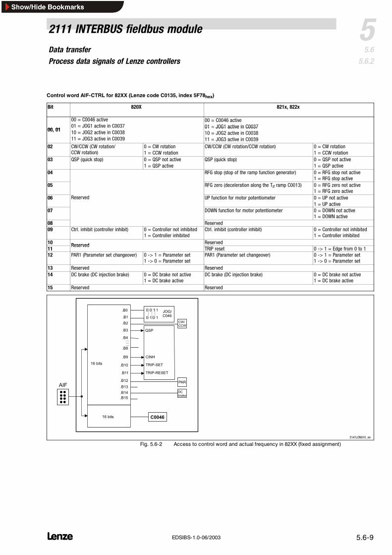
Control word AIF-CTRL for 82XX (Lenze code C0135, index 5F78hex)
Bit 820X 821x, 822x
00 01
00 = C0046 active01 = JOG1 active in C0037
00 = C0046 active01 = JOG1 active in C0037
00, 01 10 = JOG2 active in C003811 = JOG3 active in C0039
01 JOG1 active in C003710 = JOG2 active in C003811 = JOG3 active in C0039
12 PAR1 (Parameter set changeover) 0 -> 1 = Parameter set1 -> 0 = Parameter set
PAR1 (Parameter set changeover) 0 -> 1 = Parameter set1 -> 0 = Parameter set
13 Reserved Reserved14 DC brake (DC injection brake) 0 = DC brake not active
1 = DC brake activeDC brake (DC injection brake) 0 = DC brake not active
1 = DC brake active15 Reserved Reserved
AIF
C0046
.B15
.B13
.B14
.B12
.B0
.B1
.B2
.B3
.B4.........
.B8
.B9
.B10
.B11
QSP
CINH
TRIP-SET
TRIP-RESET
16 bits
16 bits
0 JOG/C046
0 1 1
0 1 0 1
PAR
DCbrake
CW/CCW
2141LON010_en
Fig. 5.6-2 Access to control word and actual frequency in 82XX (fixed assignment)
Data transferProcess data signals of Lenze controllers
5 2111 INTERBUS fieldbus module
5.65.6.2
L5.6-10 EDSIBS-1.0-06/2003
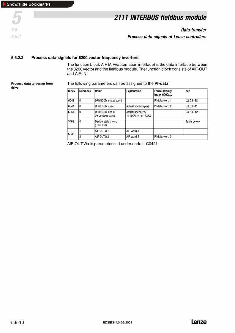
5.6.2.2 Process data signals for 8200 vector frequency inverters
The function block AIF (AIF=automation interface) is the data interface betweenthe 8200 vector and the fieldbus module. The function block consists of AIF-OUTand AIF-IN.
The following parameters can be assigned to the PI-data:
Index Subindex Name Explanation Lenze setting:Index 6000hex
see
6041 0 DRIVECOM status word PI data word 1 5.6-38
6044 0 DRIVECOM speed Actual speed [rpm] PI data word 2 5.6-41
6054 0 DRIVECOM actualpercentage value
Actual speed [%]100% =16383
5.6-42
5F69 0 Device status word(L-C0150)
Table below
5CA51 AIF-OUT.W1 AIF word 1
5CA52 AIF-OUT.W2 AIF word 2 PI data word 3
AIF-OUT.Wx is parameterised under code L-C0421.
Process data telegram fromdrive
Data transferProcess data signals of Lenze controllers
52111 INTERBUS fieldbus module
5.65.6.2
L 5.6-11EDSIBS-1.0-06/2003
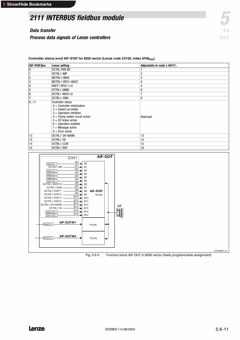
Controller status word AIF-STAT for 8200 vector (Lenze code C0150, index 5F69hex)
Fig. 5.6-3 Function block AIF-OUT in 8200 vector (freely programmable assignment)
Data transferProcess data signals of Lenze controllers
5 2111 INTERBUS fieldbus module
5.65.6.2
L5.6-12 EDSIBS-1.0-06/2003
The following parameters can be assigned to the PO-data:
Index Subindex Name Explanation Lenze setting:Index 60001hex
see
6040 0 DRIVECOM control word PO data word 1 5.6-35
6042 0 DRIVECOM speedsetpoint
Speed setpoint [rpm] PO data word 2 5.6-41
6052 0 DRIVECOM percentagesetpoint
Speed setpoint [%]100% =16383
5.6-42
5F78 0 Device control word(L-C0135)
Table below
5CA7
1 AIF-IN.W1 AIF word 1Frequency and speedare normalised with24000≡ 480 Hz.
5CA72 AIF-IN.W2 AIF word 2
Frequency and speedare normalised with24000≡ 480 Hz.
PO data word 3
AIF-IN.Wx is parameterised under code L-C0412.
Note!The assignment of the AIF-CTRL control word to PO data is onlyuseful, if the Drivecom status machine is switched off. This isachieved by entering “0” under L-C1911.
Process data telegram to drive
Data transferProcess data signals of Lenze controllers
52111 INTERBUS fieldbus module
5.65.6.2
L 5.6-13EDSIBS-1.0-06/2003
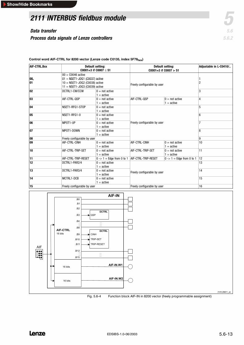
Control word AIF-CTRL for 8200 vector (Lenze code C0135, index 5F78hex)
AIF-CTRL.Bxx Default setting:C0001=3 if C0007 ≤ 51
Default setting:C0001=3 if C0007 > 51
Adjustable in L-C0410/..
00,00 = C0046 active01 = NSET1-JOG1 (C0037) active 100,
08 Freely configurable by user 909 AIF-CTRL-CINH 0 = not active
1 = activeAIF-CTRL-CINH 0 = not active
1 = active10
10 AIF-CTRL-TRIP-SET 0 = not active1 = active
AIF-CTRL-TRIP-SET 0 = not active1 = active
11
11 AIF-CTRL-TRIP-RESET 0 -> 1 = Edge from 0 to 1 AIF-CTRL-TRIP-RESET 0 -> 1 = Edge from 0 to 1 1212 DCTRL1-PAR2/4 0 = not active
1 = active13
13 DCTRL1-PAR3/4 0 = not active1 = active
Freely configurable by user 14
14 MCTRL1-DCB 0 = not active1 = active
15
15 Freely configurable by user Freely configurable by user 16
AIF
AIF-IN
AIF-CTRL
AIF-IN.W2
AIF-IN.W1
.B15
.B12
.B0
.B1
.B2
.B3
.B4 ...
......
......
......
......
......
....B8
.B9
.B10
.B11
DCTRL
QSP
CINH
TRIP-SET
TRIP-RESET
DCTRL16 bits
16 bits
16 bits
2141LON011_en
Fig. 5.6-4 Function block AIF-IN in 8200 vector (freely programmable assignment)
Data transferProcess data signals of Lenze controllers
5 2111 INTERBUS fieldbus module
5.65.6.2
L5.6-14 EDSIBS-1.0-06/2003
5.6.2.3 Process data signals for servo inverters 9300
The function block AIF (AIF = automation interface) is the data interface betweenthe 93XX controller and the fieldbus module. The function block consists ofAIF-OUT and AIF-IN.
With the 93XX controller the process data assignment can be changed byreconfiguring the function blocks AIF-IN and AIF-OUT.
Data transferProcess data signals of Lenze controllers
52111 INTERBUS fieldbus module
5.65.6.2
L 5.6-15EDSIBS-1.0-06/2003
The following parameters can be assigned to the PI-data:
Index Subindex Name (same inIEC1131)
Explanation Lenze setting:Index 6000hex
see
6041 0 DRIVECOM status word PI data word 1 5.6-38
6044 0 DRIVECOM speed Actual speed [rpm] PI data word 2 5.6-41
6054 0 DRIVECOM actualpercentage value
Actual speed [%] 5.6-42
5F69 0 Device status word(AIF1_Stat)
Table below
5CA5 1 AIF1-OUT.W1 AIF word 1
5CA5 2 AIF1-OUT.W2 AIF word 2 PI data word 3
5CA5 3 AIF1-OUT.W3 AIF word 3
5CA4 0 AIF1-OUT.D1 AIF double word
The assignment of AIF-OUT depends on the signal configuration selected underL-C0005:
Signalconfiguration(L-C0005)
AIF-OUT.W1 AIF-OUT.W2 AIF-OUT.W3 AIF-OUT.D1
Speed control
100310131113
MCTRL-NACTActual speed100%=16383
MCTRL-MSET2Torque display100%=16383
MCTRL-NSET2Speed controller input100%=16383
notassigned
Torque control
400340134113
MCTRL-MSET2Torque display100%=16383
MCTRL-NACTAct. speed in %100%=16383
MCTRL-NSET2Speed controller input100%=16383
notassigned
DF master
500350135113
MCTRL-NACTActual speed100%=16383
MCTRL-MSET2Torque display100%=16383
MCTRL-NSET2Speed controller input100%=16383
notassigned
DF-slave bus
600360136113
MCTRL-NACTActual speed100%=16383
MCTRL-PHI-ACTActual phase
MCTRL-MSET2Torque setpoint in %100%=16383
notassigned
DF-slave cascade
700370137113
MCTRL-NACTActual speed100%=16383
MCTRL-PHI-ACTActual phase
MCTRL-MSET2Torque setpoint in %100%=16383
notassigned
Not equal to xxx3(except selfconfigurations)
MCTRL-NACTActual speed100%=16383
MCTRL-MSET2Torque display100%=16383
MCTRL-PHI-ACTActual phase
notassigned
For detailed description of the 93XX signal configuration see the OperatingInstructions for 93XX (only the main configurations: 1000, 4000, 5000, etc.) or theManual 93XX.
In the controller, other signals can be assigned to AIF-OUT.W1 to AIF-OUT.W3.For this, the function-block configuration - described in theManual 93XX- is used.The function block AIF-OUT determines the output data of the controller as datainterface for the 2133 fieldbus module.
For more detailed information about the function block AIF-OUT, see the Manual93XX.
Process data telegram fromdrive
Data transferProcess data signals of Lenze controllers
Fig. 5.6-5 Function block AIF-OUT (function block extension on grey background: available asof software version 2.0 on)
Data transferProcess data signals of Lenze controllers
52111 INTERBUS fieldbus module
5.65.6.2
L 5.6-17EDSIBS-1.0-06/2003
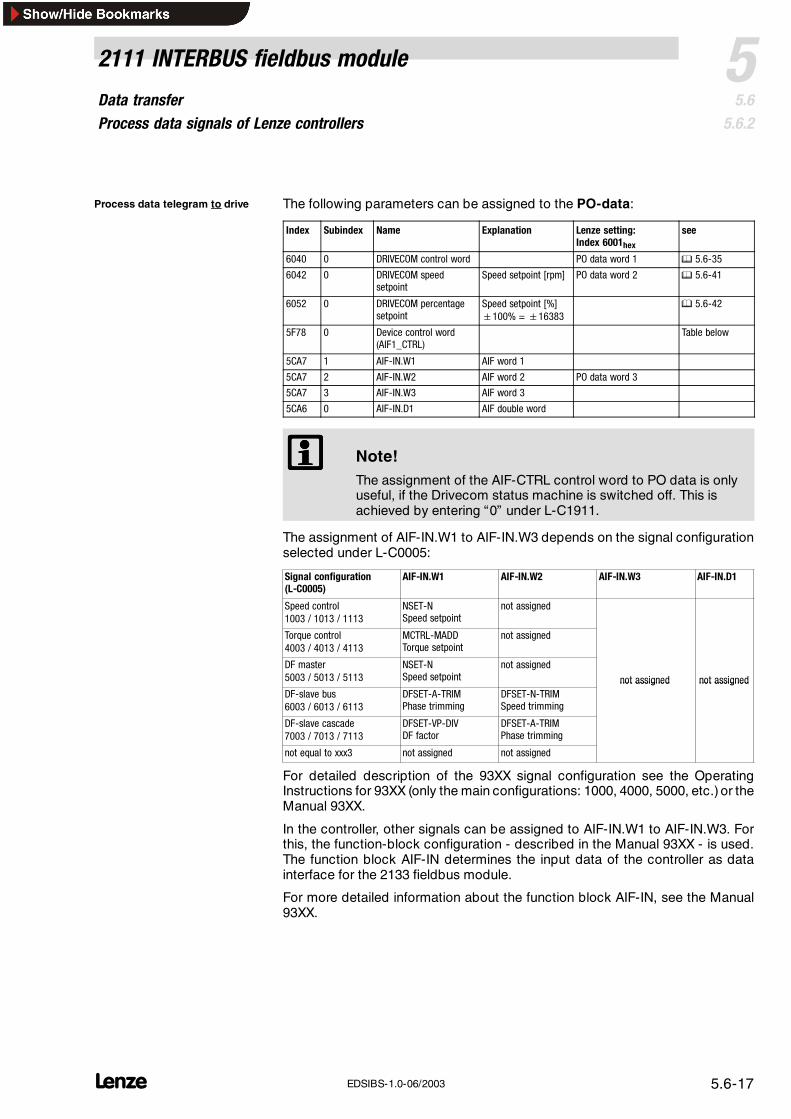
The following parameters can be assigned to the PO-data:
Index Subindex Name Explanation Lenze setting:Index 6001hex
see
6040 0 DRIVECOM control word PO data word 1 5.6-35
6042 0 DRIVECOM speedsetpoint
Speed setpoint [rpm] PO data word 2 5.6-41
6052 0 DRIVECOM percentagesetpoint
Speed setpoint [%]100% =16383
5.6-42
5F78 0 Device control word(AIF1_CTRL)
Table below
5CA7 1 AIF-IN.W1 AIF word 1
5CA7 2 AIF-IN.W2 AIF word 2 PO data word 3
5CA7 3 AIF-IN.W3 AIF word 3
5CA6 0 AIF-IN.D1 AIF double word
Note!The assignment of the AIF-CTRL control word to PO data is onlyuseful, if the Drivecom status machine is switched off. This isachieved by entering “0” under L-C1911.
The assignment of AIF-IN.W1 to AIF-IN.W3 depends on the signal configurationselected under L-C0005:
Signal configuration(L-C0005)
AIF-IN.W1 AIF-IN.W2 AIF-IN.W3 AIF-IN.D1
Speed control1003 / 1013 / 1113
NSET-NSpeed setpoint
not assigned
Torque control4003 / 4013 / 4113
MCTRL-MADDTorque setpoint
not assigned
DF master5003 / 5013 / 5113
NSET-NSpeed setpoint
not assigned
not assigned not assignedDF-slave bus6003 / 6013 / 6113
DFSET-A-TRIMPhase trimming
DFSET-N-TRIMSpeed trimming
not assigned not assigned
DF-slave cascade7003 / 7013 / 7113
DFSET-VP-DIVDF factor
DFSET-A-TRIMPhase trimming
not equal to xxx3 not assigned not assigned
For detailed description of the 93XX signal configuration see the OperatingInstructions for 93XX (only the main configurations: 1000, 4000, 5000, etc.) or theManual 93XX.
In the controller, other signals can be assigned to AIF-IN.W1 to AIF-IN.W3. Forthis, the function-block configuration - described in the Manual 93XX - is used.The function block AIF-IN determines the input data of the controller as datainterface for the 2133 fieldbus module.
For more detailed information about the function block AIF-IN, see the Manual93XX.
Process data telegram to drive
Data transferProcess data signals of Lenze controllers
5 2111 INTERBUS fieldbus module
5.65.6.2
L5.6-18 EDSIBS-1.0-06/2003
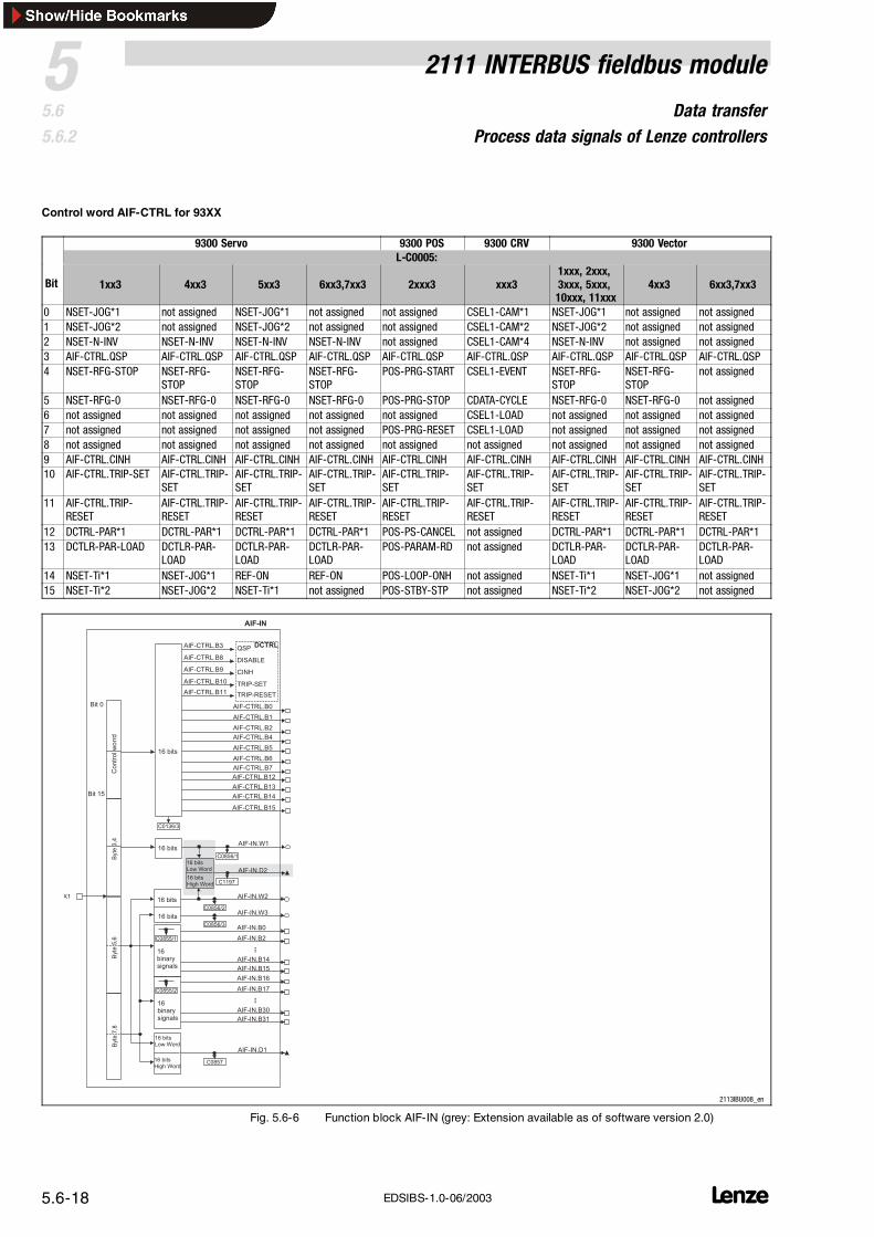
Control word AIF-CTRL for 93XX
9300 Servo 9300 POS 9300 CRV 9300 VectorL-C0005:
Bit 1xx3 4xx3 5xx3 6xx3,7xx3 2xxx3 xxx31xxx, 2xxx,3xxx, 5xxx,10xxx, 11xxx
4xx3 6xx3,7xx3
0 NSET-JOG*1 not assigned NSET-JOG*1 not assigned not assigned CSEL1-CAM*1 NSET-JOG*1 not assigned not assigned1 NSET-JOG*2 not assigned NSET-JOG*2 not assigned not assigned CSEL1-CAM*2 NSET-JOG*2 not assigned not assigned2 NSET-N-INV NSET-N-INV NSET-N-INV NSET-N-INV not assigned CSEL1-CAM*4 NSET-N-INV not assigned not assigned3 AIF-CTRL.QSP AIF-CTRL.QSP AIF-CTRL.QSP AIF-CTRL.QSP AIF-CTRL.QSP AIF-CTRL.QSP AIF-CTRL.QSP AIF-CTRL.QSP AIF-CTRL.QSP4 NSET-RFG-STOP NSET-RFG-
STOPNSET-RFG-STOP
NSET-RFG-STOP
POS-PRG-START CSEL1-EVENT NSET-RFG-STOP
NSET-RFG-STOP
not assigned
5 NSET-RFG-0 NSET-RFG-0 NSET-RFG-0 NSET-RFG-0 POS-PRG-STOP CDATA-CYCLE NSET-RFG-0 NSET-RFG-0 not assigned6 not assigned not assigned not assigned not assigned not assigned CSEL1-LOAD not assigned not assigned not assigned7 not assigned not assigned not assigned not assigned POS-PRG-RESET CSEL1-LOAD not assigned not assigned not assigned8 not assigned not assigned not assigned not assigned not assigned not assigned not assigned not assigned not assigned9 AIF-CTRL.CINH AIF-CTRL.CINH AIF-CTRL.CINH AIF-CTRL.CINH AIF-CTRL.CINH AIF-CTRL.CINH AIF-CTRL.CINH AIF-CTRL.CINH AIF-CTRL.CINH10 AIF-CTRL.TRIP-SET AIF-CTRL.TRIP-
14 NSET-Ti*1 NSET-JOG*1 REF-ON REF-ON POS-LOOP-ONH not assigned NSET-Ti*1 NSET-JOG*1 not assigned15 NSET-Ti*2 NSET-JOG*2 NSET-Ti*1 not assigned POS-STBY-STP not assigned NSET-Ti*2 NSET-JOG*2 not assigned
#
# . ! %
. ! %
# / ' / 0
# $ %
# & ' ( %
# / ' / 0
# . ! %
. !
. !
. ! "
+ $ !
+ $ !
+ $ !
+ $ !
1
/0
+ $ !
+ $ !
+ $ !
+ $ !
+ $ !
+ $ !
+ $ !
2 - + $ !
" $ 3 + $ !
. & + $ ! )
+ - 3 + $ !
+ - + 3 3 + $ !
. !
. !
. !
. !
. !
. !
#
*
*
*
*
*
)
# $ %
# & ' ( %
. ! "
*
2113IBU008_en
Fig. 5.6-6 Function block AIF-IN (grey: Extension available as of software version 2.0)
Data transferProcess data signals of Lenze controllers
52111 INTERBUS fieldbus module
5.65.6.2
L 5.6-19EDSIBS-1.0-06/2003
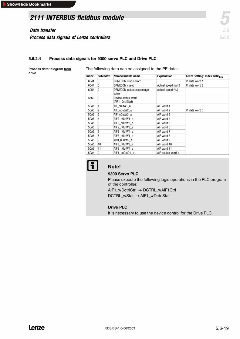
5.6.2.4 Process data signals for 9300 servo PLC and Drive PLC
The following data can be assigned to the PE data:
Index Subindex Name/variable name Explanation Lenze setting: Index 6000hex6041 0 DRIVECOM status word PI data word 16044 0 DRIVECOM speed Actual speed [rpm] PI data word 26054 0 DRIVECOM actual percentage
valueActual speed [%]
5F69 0 Device status word(AIF1_DctrlStat)
5CA5 1 AIF_nOutW1_a AIF word 15CA5 2 AIF_nOutW2_a AIF word 2 PI data word 35CA5 3 AIF_nOutW3_a AIF word 35CA5 4 AIF2_nOutW1_a AIF word 45CA5 5 AIF2_nOutW2_a AIF word 55CA5 6 AIF2_nOutW3_a AIF word 65CA5 7 AIF2_nOutW4_a AIF word 75CA5 8 AIF3_nOutW1_a AIF word 85CA5 9 AIF3_nOutW2_a AIF word 95CA5 10 AIF3_nOutW3_a AIF word 105CA5 11 AIF3_nOutW4_a AIF word 115CA4 0 AIF1_dnOutD1_p AIF double word 1
Note!9300 Servo PLCPlease execute the following logic operations in the PLC programof the controller:AIF1_wDctrlCtrl DCTRL_wAIF1CtrlDCTRL_wStat AIF1_wDctrlStat
Drive PLCIt is necessary to use the device control for the Drive PLC.
Process data telegram fromdrive
Data transferProcess data signals of Lenze controllers
5 2111 INTERBUS fieldbus module
5.65.6.2
L5.6-20 EDSIBS-1.0-06/2003
Outputs_AIF1
AutomationInterface
Byte1
Byte2
Byte3
Byte4
Byte5
Byte6
Byte7
Byte8
C0858/1
16 bitsLow Word
16 bitsHigh Word
AIF1_wDctrlStat
AIF1_nOutW1_a
16 bits
16 bits
C0858/2
AIF1_nOutW2__a
AIF1_bFDO0_b
AIF1_bFDO15_b
C0858/3
C0859
AIF1_nOutW3_a
AIF1_bFDO16_b
AIF1_bFDO31_b
16 bits
C0151/4
16 binarysignals
16 bits
C0151/4
16 binarysignals
……
AIF1_dnOutD1_p
Outputs_AIF2
AutomationInterface
...
Byte1
Byte2
Byte3
Byte4
Byte5
Byte6
Byte7
Byte8
...
16 bitsLow Word
16 bitsHigh Word
16 bits
16 binarysignals
16 bits
16 binarysignals
AIF2_nOutW2_a
AIF2_nOutW1_a
AIF2_bFDO0_b
AIF2_bFDO15_b
AIF2_bFDO16_b
AIF2_bFDO31_b
16 bits
16 bitsAIF2_nOutW4_a
AIF2_dnOutD1_p
AIF2_nOutW3_a
Outputs_AIF3
AutomationInterface
...
Byte1
Byte2
Byte3
Byte4
Byte5
Byte6
Byte7
Byte8
...
16 bitsLow Word
16 bitsHigh Word
16 bits
16 binarysignals
16 bits
16 binarysignals
AIF3_nOutW2_a
AIF3_nOutW1_a
AIF3_bFDO0_b
AIF3_bFDO15_b
AIF3_bFDO16_b
AIF3_bFDO31_b
16 bits
16 bitsAIF3_nOutW4_a
AIF3_dnOutD1_p
AIF3_nOutW3_a
Fig. 5.6-7 Function blocks AIF-OUT1, AIF-OUT2 and AIF-OUT3
Data transferProcess data signals of Lenze controllers
52111 INTERBUS fieldbus module
5.65.6.2
L 5.6-21EDSIBS-1.0-06/2003
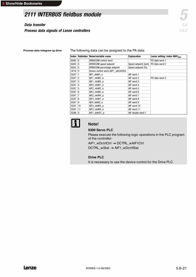
The following data can be assigned to the PA data:
Index Subindex Name/variable name Explanation Lenze setting: Index 6001hex6040 0 DRIVECOM control word PO data word 16042 0 DRIVECOM speed setpoint Speed setpoint [rpm] PO data word 26052 0 DRIVECOM percentage setpoint Speed setpoint [%]5F78 0 Device control word (AIF1_wDctrlCtrl)5CA7 1 AIF1_nInW1_a AIF word 15CA7 2 AIF1_nInW2_a AIF word 2 PO data word 35CA7 3 AIF1_nInW3_a AIF word 35CA7 4 AIF2_nInW1_a AIF word 45CA7 5 AIF2_nInW2_a AIF word 55CA7 6 AIF2_nInW3_a AIF word 65CA7 7 AIF2_nInW4_a AIF word 75CA7 8 AIF3_nInW1_a AIF word 85CA7 9 AIF3_nInW2_a AIF word 95CA7 10 AIF3_nInW3_a AIF word 105CA7 11 AIF3_nInW4_a AIF word 115CA6 0 AIF1_dnInD1_p AIF double word 1
Note!9300 Servo PLCPlease execute the following logic operations in the PLC programof the controller:AIF1_wDctrlCtrl DCTRL_wAIF1CtrlDCTRL_wStat AIF1_wDctrlStat
Drive PLCIt is necessary to use the device control for the Drive PLC.
Process data telegram to drive
Data transferProcess data signals of Lenze controllers
5 2111 INTERBUS fieldbus module
5.65.6.2
L5.6-22 EDSIBS-1.0-06/2003
Inputs_AIF1
AIF1_nInW1_a
C0856/1
16 bits
C0855/2
16 binarysignals
C0857
16 bitsLow Word
16 bitsHigh Word
AIF1_dnInD1_p
16 bits
AIF1_wDctrlCtrl
AIF1_bCtrlB0_b
AIF1_bCtrlB1_b
AIF1_bCtrlB2_b
AIF1_bCtrlQuickstop_b
AIF1_bCtrlB4_b
AIF1_bCtrlB5_b
AIF1_bCtrlB6_b
AIF1_bCtrlB7_b
AIF1_bCtrlDisable_b
AIF1_bCtrlCInhibit_b
AIF1_bCtrlTripSet_b
AIF1_bCtrlTripReset_b
AIF1_bCtrlB12_b
AIF1_bCtrlB13_b
AIF1_bCtrlB14_b
AIF1_bCtrlB15_b
16 bits
16 binarysignals
16 bits
C0855/1
16 binarysignals
AIF1_nInW2_a
C0856/2
C0856/3
AIF1_bInB0_b
AIF1_bInB15_b
……
AIF1_nInW3_a
AIF1_bIn16_b
AIF1_bIn31_b
AutomationInterface
Byte1
Byte2
Byte3
Byte4
Byte5
Byte6
Byte7
Byte8
Co
ntr
olw
ord
Inputs_AIF2
AutomationInterface
AIF2_bInB0_b
AIF2_bInB15_b
AIF2_nInW1_a16 bits
...16 binary
signals
Byte1
Byte2
Byte3
Byte4
Byte5
Byte6
Byte7
Byte8
AIF2_bInB16_b
AIF2_bInB31_b
AIF2_nInW2_a16 bits
...16 binary
signals
16 bitsLow Word
16 bitsHigh Word
AIF2_nInW3_a
AIF2_dnInD1_p
16 bits
16 bits
AIF2_nInW4_a
Inputs_AIF3
AutomationInterface
AIF3_bInB0_b
AIF3_bInB15_b
AIF3_nInW1_a16 bits
...16 binary
signals
Byte1
Byte2
Byte3
Byte4
Byte5
Byte6
Byte7
Byte8
AIF3_bInB16_b
AIF3_bInB31_b
AIF3_nInW2_a16 bits
...16 binary
signals
16 bitsLow Word
16 bitsHigh Word
AIF3_nInW3_a
AIF3_dnInD1_p
16 bits
16 bits
AIF3_nInW4_a
Fig. 5.6-8 Function blocks AIF-IN1, AIF-IN2 and AIF-IN3
Data transferProcess data preconfiguration depending on L-C0009
52111 INTERBUS fieldbus module
5.65.6.3
L 5.6-23EDSIBS-1.0-06/2003
5.6.3 Process data preconfiguration depending on L-C0009
Use L-C0009 to assign predefined values to the process data words (see tablebelow).
This preconfiguration is meant to help you with applications which do not requirea PCP.
Presettings for the process data configuration can be made under code L-C0009using the Drive PLC or any controller (82XX, 8200 vector, 93XX) even if theINTERBUS is not connected.
It is also possible to configure the fieldbus module through the parameter channelvia index 6000hex and 6001hex.
The process data configuration resulting from L-C0009 is automatically
stored in the process data description structure when the device isswitched on.Index 6000hex ( 5.6-5) / Index 6001hex ( 5.6-5).
immediately active.
automatically writes the process data length (PD) in L-C1910 andDRIVECOM in L-C1911 from the table. A change of the PD length will onlybecome active after mains switching.
The default setting of L-C0009 is “1” and influences the process dataconfiguration.
L-C0009 PD length (L-C1910) DRIVECOM (L-C1911) PD word 1 PD word 2 PD word 3
11 2 0 GSTW AIF-W1 -
12 2 0 AIF-W1 AIF-W2 -
13 2 0 AIF-W2 AIF-W3 -
14 2 1 DCSTW* DCG -
15 2 1 DCSTW* DCG % -
16 2 1 DCSTW* AIF-W1 -
17 2 0 GSTW DCG -
18 2 0 GSTW DCG % -
21 3 1 DCSTW* DCG AIF-W2
22 3 1 DCSTW* DCG % AIF-W2
23 3 1 DCSTW* AIF-W1 AIF-W2
24 3 1 DCSTW* AIF-W2 AIF-W3
25 3 0 GSTW AIF-W1 AIF-W2
26 3 0 GSTW AIF-W2 AIF-W3
27 3 0 AIF-W1 AIF-W2 AIF-W3
*GSTW:AIF-Wx:DCSTW:DCGDCG %:
5.6-29Device control word/device status wordAIF-IN/OUT.WxDRIVECOM control word/DRIVECOM status wordDRIVECOM speed [rpm]DRIVECOM speed [%]
Data transferProcess data preconfiguration depending on L-C0009
5 2111 INTERBUS fieldbus module
5.65.6.3
L5.6-24 EDSIBS-1.0-06/2003
Example 1: DRIVECOM control with 2 process data words (e.g. configuration L-C0009 = 14)Settings/measures 1. Remove the fieldbus module and disconnect it from the voltage
supply2 Set L-C0009 = 14 (e g via keypad)2. Set L-C0009 = 14 (e.g. via keypad)3. Attach the fieldbus module again and connect it to the voltage
supply
Result • The indexes 6000hex and 6001hex accept the configurations DCSTWand DCG.
• The process data length (PD) is set to 2 words by L-C1910 = 4.• DRIVECOM is activated with L-C1911 = 1.
Acceptance of settings The fieldbus module must be switched on again to activate the processdata word length.
Example 2: Device control with 2 process data words (e.g. configuration L-C0009 = 25)
Settings/measures 1. Remove the fieldbus module and disconnect it from the voltagesupply
2. Set L-C0009 = 25 (e.g. via keypad)3. Attach the fieldbus module again and connect it to the voltage
supply
Result • The indexes 6000hex and 6001hex accept the configurations GSTW,AIF-W1, AIF-W2.
• The process data length (PD) is set to 3 words by L-C1910 = 6.• DRIVECOM is activated by L-C1911 = 0.
Acceptance of settings The fieldbus module must be switched on again to activate the processdata word length.
Examples for process datapreconfiguration
Data transferExamples for the configuration of PI/PO data
52111 INTERBUS fieldbus module
5.65.6.4
L 5.6-25EDSIBS-1.0-06/2003
5.6.4 Examples for the configuration of PI/PO data
The PI data word 2 is to be assigned to the actual percentage (index = 6054hex).
Procedure:
1. Data type derived from the code table 5.6-42.– The data type of the parameter actual percentage value is I16, i.e. it is a word parameter (16 bit). The codetable for the parameter ”Process input data description structure“ (index = 6000hex) shows that the PI dataword 2 is to be entered under subindex 6 and 7 (word parameters).
– The subindex of the parameter ”PI data description“ (index = 6000hex) can be written with the PCP service”Write“ (see 5.6-49).
2. Enter the index of the parameter ”Actual percentage“: Write (index = 6000hex, subindex = 6hex, value = 6054hex)3. Enter the subindex of the parameter ”Actual percentage“: Write (index = 6000hexsubindex = 7hex, value = 0hex)
Note!The index must be changed to zero to change a subindex.You can then change the subindex before the index.
PI data configuration
Data transferExamples for the configuration of PI/PO data
5 2111 INTERBUS fieldbus module
5.65.6.4
L5.6-26 EDSIBS-1.0-06/2003
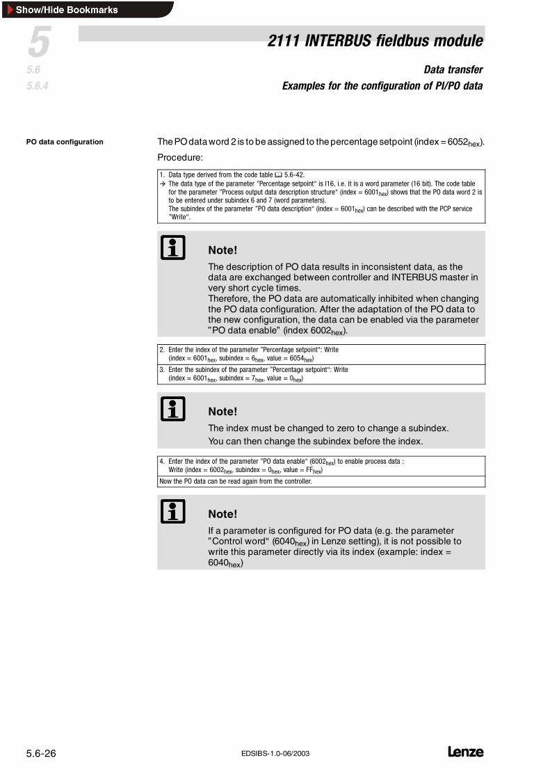
ThePOdataword 2 is to be assigned to thepercentage setpoint (index = 6052hex).
Procedure:
1. Data type derived from the code table 5.6-42. The data type of the parameter ”Percentage setpoint“ is I16, i.e. it is a word parameter (16 bit). The code table
for the parameter ”Process output data description structure“ (index = 6001hex) shows that the PO data word 2 isto be entered under subindex 6 and 7 (word parameters).The subindex of the parameter ”PO data description“ (index = 6001hex) can be described with the PCP service”Write“.
Note!The description of PO data results in inconsistent data, as thedata are exchanged between controller and INTERBUS master invery short cycle times.Therefore, the PO data are automatically inhibited when changingthe PO data configuration. After the adaptation of the PO data tothe new configuration, the data can be enabled via the parameter”PO data enable” (index 6002hex).
2. Enter the index of the parameter ”Percentage setpoint“: Write(index = 6001hex, subindex = 6hex, value = 6054hex)
3. Enter the subindex of the parameter ”Percentage setpoint“: Write(index = 6001hex, subindex = 7hex, value = 0hex)
Note!The index must be changed to zero to change a subindex.You can then change the subindex before the index.
4. Enter the index of the parameter ”PO data enable“ (6002hex) to enable process data :Write (index = 6002hex, subindex = 0hex, value = FFhex)
Now the PO data can be read again from the controller.
Note!If a parameter is configured for PO data (e.g. the parameter”Control word“ (6040hex) in Lenze setting), it is not possible towrite this parameter directly via its index (example: index =6040hex)
PO data configuration
Data transferDevice control
52111 INTERBUS fieldbus module
5.65.6.5
L 5.6-27EDSIBS-1.0-06/2003
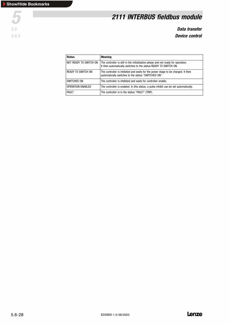
5.6.5 Device control
Note!Deactivate the DRIVECOM control if you want to use the devicecontrol (AIF-CTRL).Use code L-C1911.
If you use the device control AIF-CTRL, the control information is determined bythe control inputs (terminal) ( 5.6-3).
Explanation: Fig. 5.6-9
Status word:The controller status word AIF-STAT contains information about the currentcontroller status.
Commands– in the DRIVECOM parameter ”Control word“ are switched off and cannot
change the controller status.– for changing the controller status are to be entered through the
corresponding control input.
npmGG
`íêäK Éå~ÄäÉGG `íêäK áåÜáÄáíGG
~ìíçã~íáÅ~ääó ïÜÉåíÜÉ áåáíá~äáë~íáçå áëÅçãéäÉíÉÇ
qofm EÑ~ìäíF
qofm êÉëÉíGG
Switch on unit
pí~íìë ïçêÇ ññññ ññññ ñMññ MMMM
NOT READY TO SWITCH ON
READY TO SWITCH ON
pí~íìë ïçêÇ ññññ ññññ ñMNñ MMMN
SWITCHED ON
pí~íìë ïçêÇ ññññ ññññ ñMNñ MMNN
OPERATION ENABLED
pí~íìë ïçêÇ ññññ ññññ ñMNñ MNNN
~ìíçã~íáÅ~ääó
Fault
pí~íìë ïçêÇ ññññ ññññ ñMññ NMMM
kçíÉWqÜÉ íÉêãë ã~êâÉÇ ïáíÜ GG ~êÉ Åçãã~åÇë
Fig. 5.6-9 Status diagram for device control AIF-CTRL
Data transferDevice control
5 2111 INTERBUS fieldbus module
5.65.6.5
L5.6-28 EDSIBS-1.0-06/2003
Status Meaning
NOT READY TO SWITCH ON The controller is still in the initialisation phase and not ready for operation.It then automatically switches to the status READY TO SWITCH ON.
READY TO SWITCH ON The controller is inhibited and waits for the power stage to be charged. It thenautomatically switches to the status ”SWITCHED ON“.
SWITCHED ON The controller is inhibited and waits for controller enable.
OPERATION ENABLED The controller is enabled. In this status, a pulse inhibit can be set automatically.
FAULT The controller is in the status ”FAULT“ (TRIP).
Data transferDRIVECOM control
52111 INTERBUS fieldbus module
5.65.6.6
L 5.6-29EDSIBS-1.0-06/2003
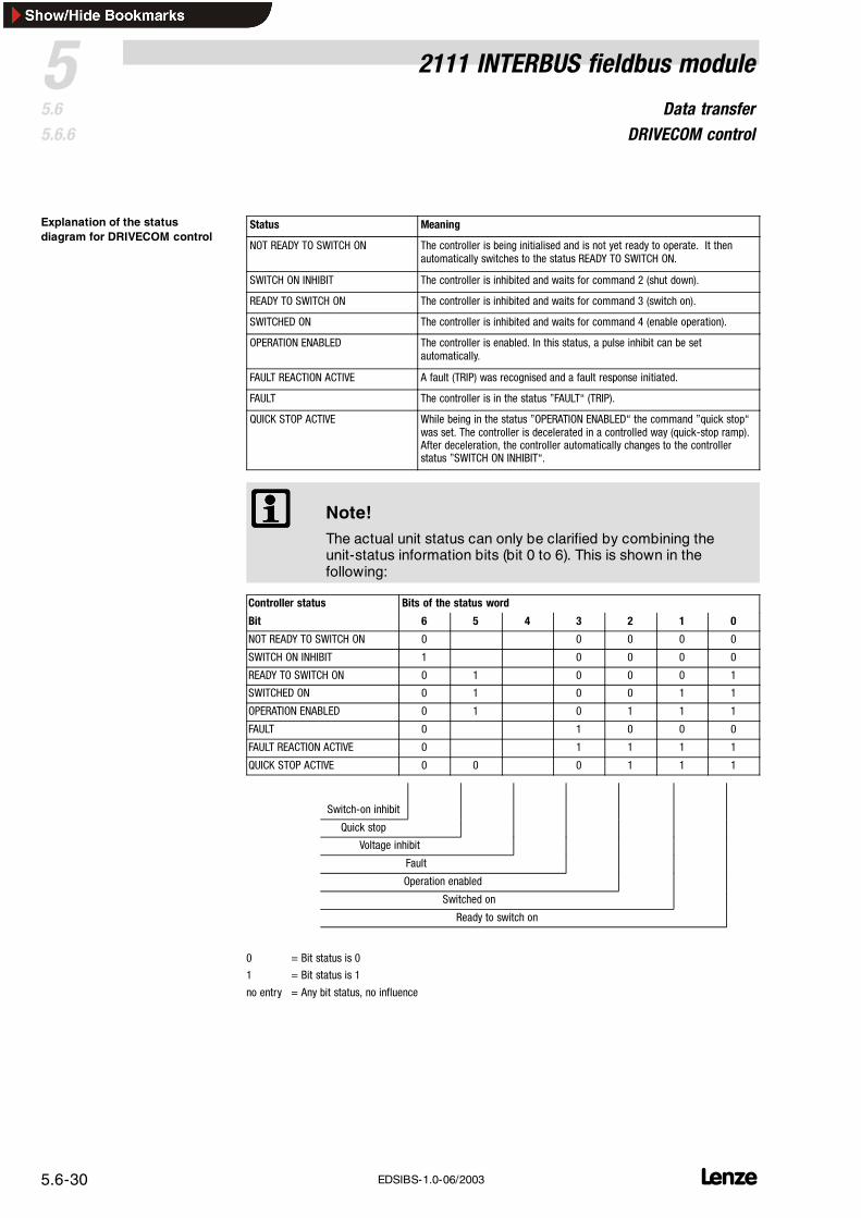
5.6.6 DRIVECOM control
With INTERBUS control (for 82XX/8200vector: Lenze parameter L-C0001 = 3; for93XX: always) and when using the fieldbus module, Lenze controllers have acontroller status according to the DRIVECOM profile 21.
Explanation: Fig. 5.6-10
The DRIVECOM parameter “Status word” contains information about thecurrent controller status. Marked by rectangles.
Commands in the DRIVECOM parameter ”Control word“ can change thecontroller status. Marked by arrows.
~ìíçã~íáÅ~ääó ïÜÉåêÉ~Åíáçå íç Éêêçê áë çîÉê
fåÜáÄáí îçäí~ÖÉññññ ññññ ññññ ññMñ
pí~åÇëíáääññññ ññññ ñññññNNM
pí~åÇëíáääññññ ññññ ñññññNNM
pïáíÅÜ çåññññ ññññ ñññññNNN
~ìíçã~íáÅ~ääó ïÜÉåíÜÉ áåáíá~äáë~íáçå áë
ÅçãéäÉíÉÇoÉëÉí Ñ~ìäíññññ ññññ Mñññ ññññ
Switch on unit
pí~íìë ïçêÇ ññññ ññññ ñMññ MMMM
NOT READY TO SWITCH ON
READY TO SWITCH ON
pí~íìë ïçêÇ ññññ ññññ ñMNñ MMMN
SWITCHED ON
pí~íìë ïçêÇ ññññ ññññ ñMNñ MMNN
OPERATION ENABLED
pí~íìë ïçêÇ ññññ ññññ ñMNñ MNNN
Fault
pí~íìë ïçêÇ ññññ ññññ ñMññ NMMM
bñ~ãéäÉWpí~íìë áåÑçêã~íáçå îá~ é~ê~ãÉíÉê Òëí~íìë ïçêÇÒEáåÇÉñ SMQNÜÉñF Äáí NR KKK Äáí M EÄáå~êóF
NOT READY TO SWITCH ON The controller is being initialised and is not yet ready to operate. It thenautomatically switches to the status READY TO SWITCH ON.
SWITCH ON INHIBIT The controller is inhibited and waits for command 2 (shut down).
READY TO SWITCH ON The controller is inhibited and waits for command 3 (switch on).
SWITCHED ON The controller is inhibited and waits for command 4 (enable operation).
OPERATION ENABLED The controller is enabled. In this status, a pulse inhibit can be setautomatically.
FAULT REACTION ACTIVE A fault (TRIP) was recognised and a fault response initiated.
FAULT The controller is in the status ”FAULT“ (TRIP).
QUICK STOP ACTIVE While being in the status ”OPERATION ENABLED“ the command ”quick stop“was set. The controller is decelerated in a controlled way (quick-stop ramp).After deceleration, the controller automatically changes to the controllerstatus ”SWITCH ON INHIBIT“.
Note!The actual unit status can only be clarified by combining theunit-status information bits (bit 0 to 6). This is shown in thefollowing:
Controller status Bits of the status word
Bit 6 5 4 3 2 1 0
NOT READY TO SWITCH ON 0 0 0 0 0
SWITCH ON INHIBIT 1 0 0 0 0
READY TO SWITCH ON 0 1 0 0 0 1
SWITCHED ON 0 1 0 0 1 1
OPERATION ENABLED 0 1 0 1 1 1
FAULT 0 1 0 0 0
FAULT REACTION ACTIVE 0 1 1 1 1
QUICK STOP ACTIVE 0 0 0 1 1 1
Switch-on inhibit
Quick stop
Voltage inhibit
Fault
Operation enabled
Switched on
Ready to switch on
0 = Bit status is 0
1 = Bit status is 1
no entry = Any bit status, no influence
Explanation of the statusdiagram for DRIVECOM control
Data transferDRIVECOM control
52111 INTERBUS fieldbus module
5.65.6.6
L 5.6-31EDSIBS-1.0-06/2003
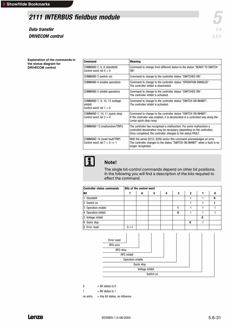
Command Meaning
COMMAND 2, 6, 8 (standstill)Control word: bit 0 = 0
Command to change from different states to the status ”READY TO SWITCHON“.
COMMAND 3 (switch on) Command to change to the controller status ”SWITCHED ON“.
COMMAND 4 (enable operation) Command to change to the controller status ”OPERATION ENABLED“.The controller inhibit is deactivated.
COMMAND 5 (inhibit operation) Command to change to the controller status ”SWITCHED ON“.The controller inhibit is activated.
Command to change to the controller status ”SWITCH ON INHIBIT“.If the controller was enabled, it is decelerated in a controlled way along theLenze quick-stop ramp.
COMMAND 13 (malfunction/TRIP)) The controller has recognised a malfunction. For some malfunction acontrolled deceleration may be necessary (depending on the controller).Once completed, the controller changes to the status FAULT.
COMMAND 14 (reset fault/TRIP)Control word: bit 7 = 0⇒ 1
With the series 821X, 8200 vector this command acknowledges an error.The controller changes to the status ”SWITCH ON INHIBIT“ when a fault is nolonger recognised.
Note!The single bit-control commands depend on other bit positions.In the following you will find a description of the bits required toeffect the command.
Controller status commands Bits of the control word
Bit 7 6 5 4 3 2 1 0
1 Standstill 1 1 0
2 Switch on 1 1 1
3 Operation enable 1 1 1 1
4 Operation inhibit 0 1 1 1
5 Voltage inhibit 0
6 Quick stop 0 1
8 Error reset 01
Error reset
RFG-zero
RFG-stop
RFG inhibit
Operation enable
Quick stop
Voltage inhibit
Switch on
0 = Bit status is 0
1 = Bit status is 1
no entry = Any bit status, no influence
Explanation of the commands inthe status diagram forDRIVECOM control
Data transferDRIVECOM profile parameters
5 2111 INTERBUS fieldbus module
5.65.6.7
L5.6-32 EDSIBS-1.0-06/2003
5.6.7 DRIVECOM profile parameters
5.6.7.1 Process data description
The description is on page ( 5.6-5).
The description is on page ( 5.6-5).
The parameter enables or inhibits the PO data (output data for INTERBUSmaster). By this, the consistency of the PO data is guaranteed.
Inhibit output data: 00hex
Enable output data: FFhex
Every bit enables a process data byte!
If you change 6001hex, the changed process data bytes will be inhibitedautomatically. That means, that the controller does not receive new control datauntil index 6002hex enables the communication again.
Parameter name (Index) Subindex Data structure Data type
Enable PO data (6002hex) 0 S OS
All process data are enabled when the device is switched on (6002hex ≡ FFhex)
PI data description (6000hex)
PO data description (6001hex)
PO data enable (6002hex)
Data transferDRIVECOM profile parameters
52111 INTERBUS fieldbus module
5.65.6.7
L 5.6-33EDSIBS-1.0-06/2003
5.6.7.2 Monitoring parameters
If the transmission of the process data is inactive for longer than the set monitoringtime (PCD watchdog), the action set in the parameter ”process-data monitoringselection code” (6004hex) will be activated.
Parameter name (Index) Subindex Data structure Data type Value range
Process data monitoring time(6003hex)
0 S OS-1OS: Octetstring,length: 4
0 - 65535(Lenze setting: 65535,monitoring is switched off)
The parameter determines the reaction of the controller after the process datamonitoring time is over (6003hex).
Parameter name (Index) Subindex Data structure Data type Value range
Process data monitoring selectioncode (6004hex)
0 S I16 0 (Lenze setting),0 = No action2:Unit control command„Inhibit voltage“ (controllerinhibit with latching in thestatus ”SWITCH ON INHIBIT“)3:Unit control command”Quick stop“ (quick stop(QSP) with latching in thestatus ”SWITCH ONINHIBIT“).
Process data monitoring time(6003hex)
Process data monitoringselection code (6004hex)
Data transferDRIVECOM profile parameters
5 2111 INTERBUS fieldbus module
5.65.6.7
L5.6-34 EDSIBS-1.0-06/2003
5.6.7.3 Error code (603Fhex)
If the drive sets TRIP, the error code transmits an error number whichcorrespondsto the DRIVECOM profile (see chapter 5.7.4 DRIVECOM error code).
A list of errors which occurred in Lenze controllers is stored under the Lenzeparameters:
82XX: L-C0162 - L-C0164
93XX: L-C0168 with subindex 1 to 8
Parameter name (Index) Subindex Data structure Data type
Error code (603Fhex) 0 S U16OS
Data transferDRIVECOM profile parameters
52111 INTERBUS fieldbus module
5.65.6.7
L 5.6-35EDSIBS-1.0-06/2003
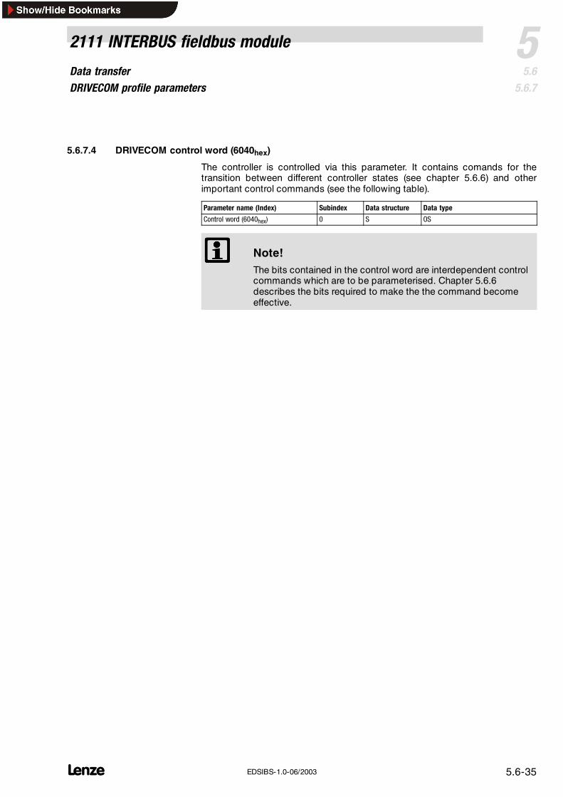
5.6.7.4 DRIVECOM control word (6040hex)
The controller is controlled via this parameter. It contains comands for thetransition between different controller states (see chapter 5.6.6) and otherimportant control commands (see the following table).
Parameter name (Index) Subindex Data structure Data type
Control word (6040hex) 0 S OS
Note!The bits contained in the control word are interdependent controlcommands which are to be parameterised. Chapter 5.6.6describes the bits required to make the the command becomeeffective.
Data transferDRIVECOM profile parameters
5 2111 INTERBUS fieldbus module
5.65.6.7
L5.6-36 EDSIBS-1.0-06/2003
Bit Name Meaning0 Switch on Controller status 0 = command 2, 6, 8 (controller inhibit)
1 = command 3 (controller inhibit)1 Voltage inhibit Controller status 0 = command 9, 10, 12 (controller inhibit)
1 = command ”voltage inhibit“ not active2 Quick stop Controller status 0 = Command 7, 10, 11 (quick stop)
1 = Command ”quick stop“ not active3 Operation
enableController status 0 = Command 5 (controller inhibit)
1 = Command 4 (controller inhibit not active)4 RFG inhibit Inhibit of the
ramp-funtiongenerator.
Quick stop is activated without the controller leaving its status.0 = RFG inhibit (quick stop)1 = RFG inhibit not active
5 FREE 820X: Not assigned5 FREE
DRIVECOM:RFG-stop
821X, 822X: Output of the RFG (speed setpoint integrator) is ”frozen”.0 = RFG stop1 = RFG stop not activeRFG stop
8200 vector, 93XX: Free. Mapping to bit AIF-CTRL.B4 negated.6 FREE 820X: Not assigned6 FREE
DRIVECOM:RFG-zero
821X, 822X: Ramp function generator input (speed setpoint integrator) = 0(controlled deceleration along the set ramp)0 = RFG zero1 = RFG zero not active
8200 vector, 93XX: Free. Mapping to bit AIF-CTRL.B5 negated.7 Error reset Fault reset (TRIP). For this, a bit change from 0 to 1 is required.
For 82XX, the controller is initialised. During this time, the controller does not accept anycommands.
8 - 10 Reserve DRIVECOM reserved11 FREE
DRIVECOM:820X, 821X, 822X: Not assigned
DRIVECOM:Manufacturer 8200 vector, 93XX: Free. Mapping to bit AIF-CTRL.B7.
12 FREEDRIVECOM:Manufacturer
820X, 821X, 822X: Parameter set changeover:0 1 = Parameter set 21 0 = Parameter set 1Manufacturer
8200 vector, 93XX: Free. Mapping to bit AIF-CTRL.B12.13 FREE
8200 vector, 93XX: Free. Mapping to bit AIF-CTRL.B13.14 FREE
DRIVECOM:820X, 821X, 822X: Not assigned
DRIVECOM:Manufacturer
8200 vector, 93XX: Free. Mapping to bit AIF-CTRL.B14.
15 FREEDRIVECOM:Manufacturer
8201X PE inhibitInhibit the update of the PO data of the controller (input data forthe master).Updates of status and current information of the process channelcan be inhibited in order to send control information moreprecisely in time (see chapter 5.3.4.2).0 = Read status and actual value1 = Do not read status and actual value
821X, 822X: Not assigned8200 vector, 93XX: Free. Mapping to bit AIF-CTRL.B15.
Structure of the DRIVECOMcontrol word
Data transferDRIVECOM profile parameters
52111 INTERBUS fieldbus module
5.65.6.7
L 5.6-37EDSIBS-1.0-06/2003
SteuerwortINTERBUS-Master
B 0
B 5
B 7
B 8
B 11
B 13
B 14
B 3
B 1
B 2
B 4
B 6
B 9
B 10
B 12
B 15
DCTRLQSP
AIF-CTRL.B3
DISABLE
CINH
TRIP-SET
TRIP-RESET
1
1
DRIVECOM StateMachine
AIF-IN
C0136/3
AIF-CTRL.B14
AIF-CTRL.B13
AIF-CTRL.B12
AIF-CTRL.B7
AIF-CTRL.B1
AIF-CTRL.B6
AIF-CTRL.B5
AIF-CTRL.B4
AIF-CTRL.B2
AIF-CTRL.B0
AIF-CTRL.B11
AIF-CTRL.B10
AIF-CTRL.B9
AIF-CTRL.B8
AIF-CTRL.B15
2113IBU006
Link between DRIVECOM controlword and AIF-CTRL control for93XX and 9300 Servo PLC
Data transferDRIVECOM profile parameters
5 2111 INTERBUS fieldbus module
5.65.6.7
L5.6-38 EDSIBS-1.0-06/2003
5.6.7.5 DRIVECOM status word (6041hex)
This parameter provides compact information about the controller. It containscommands for the transition between the different controller states (see chapter5.6.6) and other important information (see the following table).
Note!The current controller status can only be clarified by combiningthe bits with the status information (bit 0, 1, 2, 3, 4, 5 and 6). Thisis shown in chapter 5.6.6.
Parameter name (Index) Subindex Data structure Data type
Status word (6041hex) 0 S OS
Data transferDRIVECOM profile parameters
52111 INTERBUS fieldbus module
5.65.6.7
L 5.6-39EDSIBS-1.0-06/2003
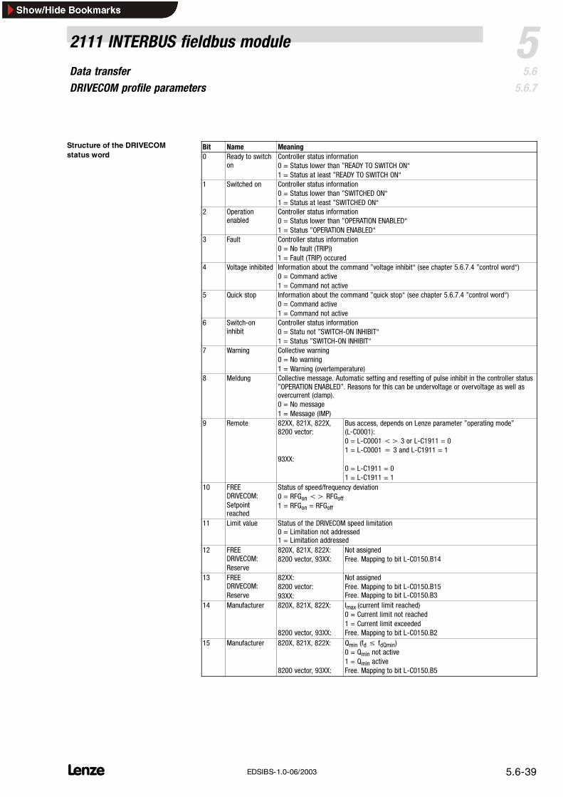
Bit Name Meaning0 Ready to switch
onController status information0 = Status lower than ”READY TO SWITCH ON“1 = Status at least ”READY TO SWITCH ON“
1 Switched on Controller status information0 = Status lower than ”SWITCHED ON“1 = Status at least ”SWITCHED ON“
2 Operationenabled
Controller status information0 = Status lower than ”OPERATION ENABLED“1 = Status ”OPERATION ENABLED“
3 Fault Controller status information0 = No fault (TRIP))1 = Fault (TRIP) occured
4 Voltage inhibited Information about the command ”voltage inhibit“ (see chapter 5.6.7.4 ”control word“)0 = Command active1 = Command not active
5 Quick stop Information about the command ”quick stop“ (see chapter 5.6.7.4 ”control word“)0 = Command active1 = Command not active
6 Switch-oninhibit
Controller status information0 = Statu not ”SWITCH-ON INHIBIT“1 = Status ”SWITCH-ON INHIBIT“
7 Warning Collective warning0 = No warning1 = Warning (overtemperature)
8 Meldung Collective message. Automatic setting and resetting of pulse inhibit in the controller status”OPERATION ENABLED”. Reasons for this can be undervoltage or overvoltage as well asovercurrent (clamp).0 = No message1 = Message (IMP)
9 Remote 82XX, 821X, 822X,8200 vector:
93XX:
Bus access, depends on Lenze parameter ”operating mode”(L-C0001):0 = L-C0001<> 3 or L-C1911 = 01 = L-C0001= 3 and L-C1911 = 1
0 = L-C1911 = 01 = L-C1911 = 1
10 FREEDRIVECOM:Setpointreached
Status of speed/frequency deviation0 = RFGon<> RFGoff1 = RFGon = RFGoff
11 Limit value Status of the DRIVECOM speed limitation0 = Limitation not addressed1 = Limitation addressed
12 FREEDRIVECOM:Reserve
820X, 821X, 822X:8200 vector, 93XX:
Not assignedFree. Mapping to bit L-C0150.B14
13 FREEDRIVECOM:Reserve
82XX:8200 vector:93XX:
Not assignedFree. Mapping to bit L-C0150.B15Free. Mapping to bit L-C0150.B3
14 Manufacturer 820X, 821X, 822X:
8200 vector, 93XX:
Imax (current limit reached)0 = Current limit not reached1 = Current limit exceededFree. Mapping to bit L-C0150.B2
15 Manufacturer 820X, 821X, 822X:
8200 vector, 93XX:
Qmin (fd≤ fdQmin)0 = Qmin not active1 = Qmin activeFree. Mapping to bit L-C0150.B5
Structure of the DRIVECOMstatus word
Data transferDRIVECOM profile parameters
5 2111 INTERBUS fieldbus module
5.65.6.7
L5.6-40 EDSIBS-1.0-06/2003
C0156/1STAT.B0
STAT.B2
STAT.B3
STAT.B4
STAT.B5
STAT.B14
STAT.B15
DCTRL-IMP
DCTRL-WARN
DCTRL-MESS
DCTRL-NACT=0
C0156/2
C0156/3
C0156/4
C0156/5
DCTRL-STAT*1
DCTRL-STAT*2
DCTRL-STAT*4
DCTRL-STAT*8
DCTRL-CINH
C0156/6
C0156/7
StatuswortINTERBUS-Master
B 0
B 5
B 7
B 8
B 11
B 13
B 14
B 3
B 1
B 2
B 4
B 6
B 9
B 10
B 12
B 15
DRIVECOM StateMachine
STAT
2113IBU007
Link between DRIVECOM statusword and function block STATfor 93XX and 9300 Servo PLC
Data transferDRIVECOM profile parameters
52111 INTERBUS fieldbus module
5.65.6.7
L 5.6-41EDSIBS-1.0-06/2003
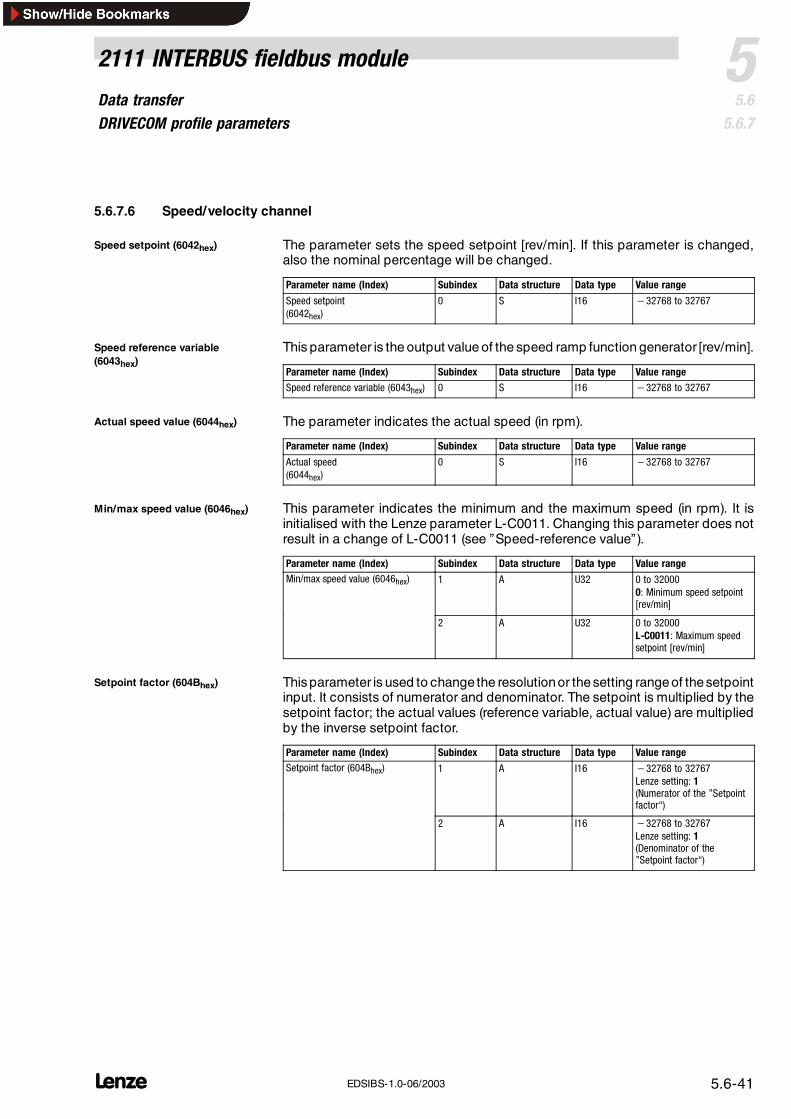
5.6.7.6 Speed/velocity channel
The parameter sets the speed setpoint [rev/min]. If this parameter is changed,also the nominal percentage will be changed.
Parameter name (Index) Subindex Data structure Data type Value range
Speed setpoint(6042hex)
0 S I16 −32768 to 32767
This parameter is the output value of the speed ramp function generator [rev/min].
Parameter name (Index) Subindex Data structure Data type Value range
Speed reference variable (6043hex) 0 S I16 −32768 to 32767
The parameter indicates the actual speed (in rpm).
Parameter name (Index) Subindex Data structure Data type Value range
Actual speed(6044hex)
0 S I16 −32768 to 32767
This parameter indicates the minimum and the maximum speed (in rpm). It isinitialised with the Lenze parameter L-C0011. Changing this parameter does notresult in a change of L-C0011 (see ”Speed-reference value”).
Parameter name (Index) Subindex Data structure Data type Value rangeMin/max speed value (6046hex) 1 A U32 0 to 32000
0: Minimum speed setpoint[rev/min]
2 A U32 0 to 32000L-C0011: Maximum speedsetpoint [rev/min]
This parameter is used to change the resolutionor thesetting rangeof thesetpointinput. It consists of numerator and denominator. The setpoint is multiplied by thesetpoint factor; the actual values (reference variable, actual value) are multipliedby the inverse setpoint factor.
Parameter name (Index) Subindex Data structure Data type Value rangeSetpoint factor (604Bhex) 1 A I16 −32768 to 32767
Lenze setting: 1(Numerator of the ”Setpointfactor“)
2 A I16 −32768 to 32767Lenze setting: 1(Denominator of the”Setpoint factor“)
Speed setpoint (6042hex) 11
Speed reference variable(6043hex)
Actual speed value (6044hex) 12
Min/max speed value (6046hex)
Setpoint factor (604Bhex)
Data transferDRIVECOM profile parameters
5 2111 INTERBUS fieldbus module
5.65.6.7
L5.6-42 EDSIBS-1.0-06/2003
The parameter indicates the pole number of asynchronous motors and is used toconvert frequency values into speed values. Only even values are possible.
Parameter name (Index) Subindex Data structure Data type Value range
Pole number (604Dhex) 0 S U8 2, 4, 6, ..., 254Lenze setting: 4
This parameter is the reference value for the relative speed parameters, e.g.nominal percentage, actual percentage and acceleration time. The parameter ismapped to the Lenze parameter L-C0011. A conversion to frequency values ispossible. The parameter determines the internal maximum speed, which is alsoactive with terminal control.
Parameter name (Index) Subindex Data structure Data type Meaning
Speed reference value (604Ehex) 0 S U32L-C0011
2in [rev∕min]
This parameter is the nominal speed in percent. It is scaled to the ”speedreference value“ (= 100 %). When changing this parameter, also the ”nominalspeed“ will be changed. If the ”nominal speed“ exceeds the limit value of the”nominal percentage“ of 200 % during reading, it will be returned as a valuelimited to 200 %.
Parameter name (Index) Subindex Data structure Data type Value range
Percentage setpoint (6052hex) 0 S I16 −32768 to 32767(100 % = 16383)
This parameter is the ”speed reference variable“ in percent. It is scaled to the”speed reference value“ (= 100 %). The ”percentage reference variable“ ismultiplied by the inverse ”setpoint factor“.
Parameter name (Index) Subindex Data structure Data type Value range
Percentage reference variable(6053hex)
0 S I16 −32768 to 32767(100 % = 16383)
This parameter is the ”actual speed“ in percent. It is scaled to the ”speedreference value“.
Parameter name (Index) Subindex Data structure Data type Value range
Actual percentage (6054hex) 0 S I16 −32768 to 32767(100 % = 16383)Map of L-C0381
Pole number (604Dhex) 13
Speed reference value (604Ehex)
Percentage setpoint (6052hex) 14
Percentage reference variable(6053hex)
Actual percentage (6054hex) 15
Data transferDRIVECOM profile parameters
52111 INTERBUS fieldbus module
5.65.6.7
L 5.6-43EDSIBS-1.0-06/2003
5.6.7.7 Ramps
The DRIVECOM profile 21 provides two ramps for the speed setpoint:
The absolute ramp is determined by the following ramp gradient:
dê~ÇáÉåí= aÉäí~|ëéÉÉÇaÉäí~|íáãÉ
The absolute ramps in the DRIVECOM profile 21 are ”acceleration”,”deceleration” and ”quick stop”.
The relative ramp is determined by the following ramp gradient:
dê~ÇáÉåí= péÉÉÇ êÉÑÉêÉåÅÉ î~äìÉaÉäí~|íáãÉ
This definition corresponds to the Lenze ramp functions L-C0012 and L-C0013.The relative ramps in the DRIVECOM profile 21 are ”acceleration time”,”deceleration time” and ”quick-stop time”.
The ”ramp-min function” determines and activates the slower ramp. Theabsoluteramps are deactivated in Lenze setting.
This parameter contains data of the absolute speed ramp for acceleration.
Ramp gradient:
Gradient= Delta_speedDelta_time
The parameter is mapped to the Lenze acceleration ramp (L-C0012) via the”ramp-min-function”.
”Delta_time“ = 0: Ramp is switched off.
Parameter name (Index) Subindex Data structure Data type Value rangeSpeed acceleration (6048hex) 1 RS (21hex) U32 0 to 4294967295
0: Delta_speed [rev/min]
2 RS (21hex) U16 0 to 655350 (ramp is switched off):Delta_time [sec]
The ”ramp-min function” determines and activates the slower ramp. Theabsoluteramps are deactivated in Lenze setting.
Speed ramps fro acceleration(6048hex)
Data transferDRIVECOM profile parameters
5 2111 INTERBUS fieldbus module
5.65.6.7
L5.6-44 EDSIBS-1.0-06/2003
This parameter contains data of the absolute speed ramp for deceleration.
Ramp gradient:
Gradient= Delta_speedDelta_time
The parameter is mapped to the Lenze deceleration ramp (L-C0013) via the”ramp-min-function”. If the ”delta_time“ = 0, the ramp is switched off.
Parameter name (Index) Subindex Data structure Data type Value rangeSpeed delay (6049hex) 1 RS (21hex) U32 0 to 4294967295
0: Delta_speed [rev/min]
2 RS (21hex) U16 0 to 655350 (ramp is switched off):Delta_time [sec]
This parameter contains the data of the absolute speed ramp for deceleration inthe status ”QUICKSTOP“ or ”CTRL INHIBIT“ or the QSP terminal function.
Ramp gradient:
Gradient= Delta_speedDelta_time
The parameter is mapped to the Lenze quick-stop ramp (L-C0105) via the”ramp-min-function”. If the ”delta_time“ = 0, the ramp is switched off.
Parameter name (Index) Subindex Data structure Data type Value rangeQuick stop(604Ahex)
1 RS (21hex) U32 0 to 42949672950: Delta_speed [rev/min]
2 RS (21hex) U16 0 to 655350 (ramp is switched off):Delta_time [sec]
This parameter is for the accelerationof the relative speed ramp. Theaccelerationtime refers to the parameter ”speed reference” with the following slope:
Ramp gradient:
Gradient=Speed reference value (604Ehex)Acceleration time (604Fhex)
The parameter is mapped to the Lenze acceleration ramp (L-C0012) via the”ramp-min-function”. If the ”acceleration time“ = 0, the ramp is switched off.
Parameter name (Index) Subindex Data structure Data type Value range
Acceleration time (604Fhex) 0 S U32 0 to 495000 [ms](max. L-C0012 / 2)
Speed ramps for deceleration(6049hex)
Speed quick stop (604Ahex)
Acceleration time (604Fhex)
Data transferDRIVECOM profile parameters
52111 INTERBUS fieldbus module
5.65.6.7
L 5.6-45EDSIBS-1.0-06/2003
This parameter is for the decelerationof the relative speed ramp. Thedecelerationtime refers to the parameter ”Speed reference value“.
Ramp gradient:
Gradient=Speed reference value (604Ehex)Deceleration time (6050hex)
The parameter is mapped to the Lenze deceleration ramp (L-C0013) via the”ramp-min-function”. If the „deceleration time“ = 0, the ramp is switched off.
Parameter name (Index) Subindex Data structure Data type Value range
Deceleration time (6050hex) 0 S U32 0 to 495000 [ms](max. L-C0013 / 2)
This parameter is assigned to the relative speed ramp for the unit-controlcommands ”quick stop” and ”CTRL inhibit” or the QSP terminal function. Thequick stop time refers to the parameter ”Speed reference value“.
Ramp gradient:
Gradient=Speed reference value (604Ehex)
Quich stop time (6051hex)
The parameter is mapped to the Lenze quick-stop ramp (L-C0105) via the”ramp-min-function”. If the ”quick stop time“ = 0, the ramp is switched off.
Parameter name (Index) Subindex Data structure Data type Value range
Quick-stop time (6051hex) 0 S U32 0 to 495000 [ms](max. L-C0105 / 2)
Deceleration time (6050hex)
Quick-stop time (6051hex)
Data transferConfiguration of the parameter data channel (PCP communication)
5 2111 INTERBUS fieldbus module
5.65.6.8
L5.6-46 EDSIBS-1.0-06/2003
5.6.8 Configuration of the parameter data channel (PCP communication)
5.6.8.1 General information
The behaviour and features of a device connected to the INTERBUS can bechanged through the INTERBUS master. The device is connected via theattached fieldbus module. All devices ( 5.2-1) can be connected to the bus.
Features and behaviour can be changed by changing the parameter data of thebasic unit. Parameter data are
Lenze parameters (L- Cxxxx)– Lenze parameters are implemented in Lenze controllers or fieldbus
modules.– In these descriptions Lenze parameters are marked by an L followed by
the code as indicated in the corresponding controller description (“C” and4-digit code number).
DRIVECOM parameters– For more all manufacturers– Normalisation in DRIVECOM profile 21– Every DRIVECOM parameter is addressed by the corresponding index
(overview in chapter 5.8.1.3).
Lenze controllers store the parameters to be changed incodes.
Note!These Instructions use a ”L-Cxxxx“ in front of a code to indicatethat it is a Lenze code and not a DRIVECOM index.Example: ’L-C0001’ stands for the Lenze code C0001.
Controller codes are addressed via the index when they areaccessed through thebus module.
The index for Lenze code numbers is between 16576 (40C0hex) and 24575 (5FFFhex).
The value range for Lenze codes can be found in the Operating Instructions forthe corresponding controller (see: Code table).
The data of the Lenze parameters are mainly represented in a fixed-point formatof the data type Integer32 with four decimal digits. This means, that theparametervalue listed in the Operating Instructions must be multiplied by 10000.
Example:
dec hexL-C0039 (JOG) = 150.4 Hz 150.4 x 10000 = 1504000 = 0016F300
Access to controller codes
Data transferConfiguration of the parameter data channel (PCP communication)
52111 INTERBUS fieldbus module
5.65.6.8
L 5.6-47EDSIBS-1.0-06/2003
Lenze parameter sets
Parameter sets are for special code saving which is necessary because ofdifferent configurations for different application processes.
The following table informs about number and addressing of parameter sets foryour controller:
82XX 8200 vector 93XXThe 82XX and 8200 vector have 2 and 4 parameter sets. Theparameters can be directly addressed via INTERBUS.They are addressed by means of a code-digit offset:
93XX controllers have 4 parameter sets(depending on the variant). They are savedin the EEPROM of the controller.
• Offset 0 addresses parameter set 1 with the Lenze codes L-C0000to L-C1999
• Offset 2000 addresses parameter set 2 with the Lenze codesL-C2000 to L-C3999
in the EEPROM of the controller.Another parameter set is in the usermemory of the controller. This parameterset can be changed by the user.• After switch-on parameter set 1 is
No additionalparameter sets available.
• Offset 4000 addresses parameter set 3with the Lenze codes L-C4000 toL-C5999
• Offset 6000 addresses parameter set 4with the Lenze codes L-C6000 toL-C7999
After switch on parameter set 1 isautomatically loaded as currentparameter set.
• Parameter sets 2 - 4 must be loadedmanually to the RAM.
Only the parameter set directly stored inIf a parameter is available only once (see Operating Instructions for82XX or 8200 vector), use the code digit offset 0.
Only the parameter set directly stored inthe RAM can be addressed viaINTERBUS.
Example for L-C0011 (maximum field frequency):L-C0011 in parameter set 1: Lenze code = 11L-C0011 in parameter set 2: Lenze code = 2011
-
L-C0011 in parameter set 3:Lenze code = 4011L-C0011 in parameter set 4:Lenze code = 6011
Parameter changesAutomatic saving in thecontroller
Automatic saving is default setting(changeable under L-C0003)
Changes must be stored in code L-C0003.All changes made without storing them willbe lost after the controller is switched off.
Process data changesNo automatic saving No automatic saving No automatic saving
Stop!
For 8200 vector– Please observe that cyclic writing of parameter data into the
EEPROM is not permissible.– Please configure the code to C0003 = 0 after each mains
disconnection if you want to change the parameter datacyclically.
For 82XX– Please observe that cyclic writing of parameter data into the
EEPROM is not permissible.
Data transferConfiguration of the parameter data channel (PCP communication)
5 2111 INTERBUS fieldbus module
5.65.6.8
L5.6-48 EDSIBS-1.0-06/2003
5.6.8.2 Initialisation of PCP communication
CRL entries
CRL (Communication Reference List) entries are required to ensurecommunication between the INTERBUS master and the fieldbus module.
The following entries are to be set in the INTERBUS-master CRL:
Field name Entry
Communication reference (CR) 2
Connection type Acyclic master/slave
Connection attribute Defined
Max PDU sending high prio 0
Max PDU sending low prio 64
Max PDU receiving high prio 0
Max PDU receiving low prio 64
Supported service request 80 30 00hex
Supported Services Response 00 00 00hex
Maximum SCC 1
Maximum RCC 1
Maximum SAC 1
Maximum RAC 1
5.6.8.3 Available PCP services
In the following, you will find all the parameters and their contents which arereturned by Lenze controllers. All other transmission parameters of the statedPCP services can be obtained from the corresponding INTERBUS masterdescription.
Parameters are transmitted via the PCP channel (PCP = PeripherialsCommunication Protocol). This is carried out via PCP services.
The following PCP services are supported by Lenze controllers:
Initiate: Build up connection between INTERBUS master and controller( 5.6-49)
Abort: Disconnect ( 5.6-49)
Read: Read parameters ( 5.6-49)
Write: Write parameters ( 5.6-49)
Get-OV: Read object directory (OV) ( 5.6-50)
Identify: Identification of controller ( 5.6-50)
Status: Read controller status ( 5.6-51)
Data transferConfiguration of the parameter data channel (PCP communication)
52111 INTERBUS fieldbus module
5.65.6.8
L 5.6-49EDSIBS-1.0-06/2003
The PCP service ” Initiate“ creates a logic between the INTERBUS master and thefieldbus module. The controller returns the following parameters:
Name Value Meaning
Profile number 21hex DRIVECOM profile of version 1
Password 0 Password function of INTERBUS not supported
Access groups 0 No access groups
Access protection supported TRUE Access protection is supported
Version OV 0 Version of the object directory
The PCP service ”Abort“ interrupts a logic between the INTERBUS master andthe fieldbus module.
The PCP service ”Read“ reads parameters from the controller. The controllertransmits the required parameter or a fault message.
The PCP service ”Write“ writes controller parameters.The controller transmits apositive or negative acknowledgement or a fault message.
The following fault messages can occur:
Errorclass
Errorcode
Additional code Meaning
6 3 00hex No access
6 5 10hex Invalid service parameter
6 5 11hex Invalid subindex
6 5 12hex Data too long
6 5 13hex Data too short
6 6 00hex Object is not a parameter
6 7 00hex Object does not exist
6 8 00hex Data types are not identical
8 0 00hex Service cannot be executed
8 0 20hex Service cannot be executed currently
8 0 21hex Cannot be executed because of local control
8 0 22hex Cannot be executed because of unit status
8 0 30hex Leave value range/parameter can only be changed while controller isinhibited
8 0 31hex Parameter value too high
8 0 32hex Parameter value too small
8 0 33hex Subparameter out of value range
8 0 34hex Subparameter value too high
8 0 35hex Subparameter value too small
8 0 36hex Maximum value smaller than minimum value
8 0 41hex Communication object cannot be mapped to process data
8 0 42hex Process-data length exceeded
8 0 43hex Collision with other values
Initiate16
Abort17
Read and write18
Data transferConfiguration of the parameter data channel (PCP communication)
5 2111 INTERBUS fieldbus module
5.65.6.8
L5.6-50 EDSIBS-1.0-06/2003
The PCP service ”Get-OV“ reads the object description for each parameter anddata type.
The PCP service ” Identify“ informs about the controller identification. Thecontroller returns the following parameters:
Name Value Meaning
Name of the manufacturer ”Lenze“ (as visible string) Company name
Controller name Visible string with 15characters
Unit name for controller and bus-interface module
Controller version Visible string with 15characters
Software version of the controller
Controller name
The visible string consists of the following characters:
Characters 1 to 5: Name of the controller(4 characters for the controller name plus 1 blank)
Characters 6 to 10: Name of the fieldbus module(4 characters for the controller name plus 1 blank)
Characters 11 to 15: No name(5 blanks)
If a fieldbus module is not available, the corresponding area will be filled withblanks.
Example:
8200 vector controller with 2113 fieldbus module: ”8212 2113“
sáëáÄäÉ ëíêáåÖ
`çåíêçääÉê å~ãÉ_~ëáÅ ìåáí
`çåíêçääÉê å~ãÉcáÉäÇÄìë ãçÇìäÉ
_ä~åâ
8 2 1 2 2 1 1 3N S NN NR
Controller version
The visible string consists of the following characters:
Characters 1 to 5: software version of the controller:
– 2 characters for the basic version– 2 characters for the variant
– 1 character for the version of the variant
Characters 6 to 10: software version of the fieldbus module– 2 characters for the basic version
– 2 characters for the variant– 1 character for the version of the variant
Characters 11 to 15: No name
– 5 blanks
Get-OV19
Identify20
Data transferConfiguration of the parameter data channel (PCP communication)
52111 INTERBUS fieldbus module
5.65.6.8
L 5.6-51EDSIBS-1.0-06/2003
Example:
For a 8200 controller 8201 (version V2.1; without variant and variant version)withfieldbus module (version V1.0; without variant and variant version): ”2100010000“
sáëáÄäÉ ëíêáåÖ
`çåíêçääÉê îÉêëáçå_~ëáÅ ìåáí
`çåíêçääÉê îÉêëáçåcáÉäÇÄìë ãçÇìäÉ
_ä~åâ
2 1 0 0 1 0 0 00 0N S NN NR
The PCP service ”Status“ informs about the controller status.
The controller returns the following parameters:
Status Value Meaning
Logical status 0 = ready to communicate Information about the current operating mode(L-C0001) of the controller concerning communication
Physical status • 0 = ready for operationController status ”OPERATIONENABLED“
• 1 = partly ready for operationAll other controller states
Information about the current operating state of thecontroller.For the controller status see 5.6-29.
Local detail Parameter ”Status word“ 24-bit value comprising:• Bit 0 to 15: Profile parameter ”Status word“
(Index = 6041hex)• Bit 16 to 23: value 0
Status21
TroubleshootingController is inhibited
52111 INTERBUS fieldbus module
5.75.7.1
L 5.7-1EDSIBS-1.0-06/2003
5.7 Troubleshooting
5.7.1 Controller is inhibited
The controller cannot be enabled via INTERBUS process data, i.e. the status”OPERATION ENABLED” will not be reached.
N
fkqbo_rpfåáíá~äáë~íáçå
çâ\
fkqbo_rpÅÜÉÅâ
`ÜÉÅâ ONNPÑáÉäÇÄìë ãçÇìäÉ
fë íÜÉ óÉääçï ibaE_rpF ÄäáåâáåÖ\
UOuuWpÉí íÜÉ çéÉê~íáåÖ ãçÇÉ
EiJ`MMMNF íç P EáÑ åÉÅÉëë~êóIëíçêÉ é~ê~ãÉíÉê EiJ`MMMPFF
Short test of the INTERBUS system in the event of faulty initialisation. Thediagnostics information of the INTERBUS fieldbus modules must be consideredby the INTERBUS master.For troubleshooting it can be useful to reduce the bus so that only one unit isconnected to the INTERBUS.
DRIVECOM fault codes, which can be generated at present:
Lenze errorabbreviation
Lenze error no. DRIVECOM error code [hex] Meaning
0 0 No error
OC3 13 2213 Overcurrent during acceleration
OC4 14 2214 Overcurrent during deceleration
OC 10 2300 Overcurrent
OC5 15 2311 I*t monitoring
OC7 17 2311 I*t –monitoring limit 2
OC6 16 2312 I2t monitoring
OC1 11 2320 Short circuit, overload
OC2 12 2330 Earth fault
OU 20 3000 Overvoltage (operating status)
LP1 32/182 3130 Phase failure
US1 40 3140 Mains frequency error
US3 42 3141 Mains frequency too high
US2 41 3142 Mains frequency too low
OUE 22 3212 Overvoltage error
OH51 203 4000 PTC overtemperature
OH / OH2/4 50/52/54 4210 Heatsink overtemperature
OH3/7/8 53/57/58 4310 Motor overtemperature
OH1 51 4410 Supply module overtemperature
H08 108 5000 Hardware error
U15 70 5111 Vcc15 supply interrupted
H07 107 5200 Power stage detection
H10 110 5210 Heatsink temperature sensor error
H11 111 5210 Inside temperature sensor error
RST 76 6000 Auto-Trip-Reset error
H05 105 6000 Version error
CCr 71 6010 System error
Per/Pr5 74/79 6100 Program error
201-219 6200 Overrun or float error
230 6200 No PLC program
231 6200 LenzeXXX.lib not supported
P17 167 6200 TP control error
220 6300 No technology unit
Pr0 75 6300 Gen. parameter set error
Pr1 72 6301 Parameter set 1 error
Pr2 73 6302 Parameter set 2 error
Pr3 77 6303 Parameter set 3 error
Pr4 78 6304 Parameter set 4 error
Id1 140 6320 Faulty parameter identification
Sd5-8 85-88 7300 Setpoint encoder
PTs 81 7301 Analog encoder defective
Pr6 80 7302 Wrong encoder polarity
Sd2 82 7303 Open circuit at resolver
Sd3 83 7305 Incremental encoder 1
Sd4 84 7306 Incremental encoder 2
P09 159 8000 Error code monitoring
TroubleshootingDRIVECOM error codes
5 2111 INTERBUS fieldbus module
5.75.7.4
L5.7-6 EDSIBS-1.0-06/2003
Lenze errorabbreviation
MeaningDRIVECOM error code [hex]Lenze error no.
CE0 61 8100 AIF time monitoring
CE1.4CE11-14
62-65122-125
8100 CAN time monitoring
CE5 66 8100 CAN time OUT
P16 166 8100 Sync telegram transmission error
240 8100 Free CAN obj. send memory overflow
241 8100 Free CAN obj. too many telegramsreceived
P18 168 8200 Internal limitation
NMAX 200 8400 Nmax system speed
P04 154 8500 Negative position error
P05 155 8500 Positive position error
P06 156 8500 Home position not known
P07 157 8500 Absolute program set mode
P08 158 8500 Act. home position exceeding positionlimits
P12 162 8500 Encoder area error
P13 163 8500 Angle overrun
P03,14,15 153/164-165 8611 Contouring error
P21 171 8611 RC contouring error
P01 151 8612 Limit-stop switch negative
P02 152 8612 Limit-stop switch positive
EEr 91 9000 External trip
Note!
Only faults and errors caused by the controller can occur.Please read the Operating Instructions for the controller.
AppendixCode table
52111 INTERBUS fieldbus module
5.85.8.1
L 5.8-1EDSIBS-1.0-06/2003
5.8 Appendix
5.8.1 Code table
5.8.1.1 Codes of the 2111 INTERBUS fieldbus module
These codes determine the software used.
Software version and date can be read.
Code Values Lenze setting Explanation
L-C1810 33S2111I_xy000 Software registration number of 2111
L-C1811 Software creation date [mmm tt jjjj hh:mm:ss]
Here you can enter the number of transferred process data words in bytes.
The number of process data can have up to 6 bytes. L-C1910 can be written withthevalues 4and 6. Thevalue is saved in the EEPROM of the2113 fieldbus module.A change of process data length only becomes effective after a basic initialisationof the fieldbus module, i.e. after switching off the supply voltage.
A value higher than 4 bytes should only be used for 93XX and 8200 vector sinceonly here the data can be passed on. However, a length of > 4 bytes is possiblewith 82XX.
Code Values Lenze setting Explanation
L-C1910 4, 6 4 INTERBUS process data length in bytes
Here you can set the unit or DRIVECOM control if all DIP switches are “OFF” . Thesetting is only active then.
Code Values Lenze setting Explanation
L-C1911 0/1 1 • 1:The control word is transmitted from the INTERBUS masterto the controller via the DRIVECOM status machine.
L-C0009 Process data preconfiguration Please see the notes in chapter 5.6.3
L-C0142 This parameter L-C0142 prevents the drive from uncontrolledrestarts after:• Mains switching• Internal fault• Internal message (with pulse inhibit) > 0.5 sIf the controller sets the status ”message” because of a failure(e.g. short mains failure) and the fault remains active forlonger than 0.5 s, controller inhibit will be set automatically.The parameter L-C0142 has the following function:• L-C0142 = 1:
The drives will restart automatically as soon as the errorhas been eliminated.
• L-C0142 = 0:The controller remains inhibited and the drive cannotrestart even if the error has been eliminated.– The drive restarts after a LOW-HIGH transition at one ofthe inputs for ”controller inhibit” (CINH, e.g. at terminalX5/28) wieder an
All codes are described in detail in the corresponding Operating Instructions.
AppendixCode table
52111 INTERBUS fieldbus module
5.85.8.1
L 5.8-3EDSIBS-1.0-06/2003
5.8.1.3 Code table for the DRIVECOM profile 21
Explanation of the following code tables:
Name MeaningR/W Write/read authorization via LECOM
Ra = only read access permitted
Ra/W = Read access always permitted, write access permitted under certain conditions (e.g.depending on Lenze parameter L-C0001 (operating mode) or controller status)
PD Mapping to INTERBUS process data (index 6010hex, 6011hex)
PI = Process input data (from the controller to the host)
PO = Process output data (from the host to the controller)
POI = Process input and output data (see PO and PI)
- = Mapping of the process data not possibleSP Non-voltatile saving of the parameter
y = Yes Parameter will be saved
n = No Parameter will not be saved
- = Parameter depends on the process and will therefore not be savedData str. Data structure
S = Simple variableThe parameter consists of one value and can only be addressed via subindex 0.
A = Array variable (field parameter)The parameter contains several values of the same data type. The individual elements canbe directly addressed by means of the subindex. Subindex = 0 addresses the wholeparameter contents.
R = Record variable (combined parameter)The parameter contains several values of different data types. Subindex = 0 addresses thewhole parameter contents.