3491 Mission Oaks Blvd., Camarillo, CA 93011Visit our Web site at: http://www.harborfreight.com
Copyright 2004 by Harbor Freight Tools®. All rights reserved. No portion of thismanual or any artwork contained herein may be reproduced in any shape or form
without the express written consent of Harbor Freight Tools.For technical questions, please call 1-800-444-3353.
TO PREVENT SERIOUS INJURY,READ AND UNDERSTAND ALL WARNINGS
AND INSTRUCTIONS BEFORE USE.
Model 92281
PRODUCT SPECIFICATIONS
SAVE THIS MANUAL
You will need this manual for the safety warnings and precautions, assembly, operating,inspection, maintenance and cleaning procedures, parts list and assembly diagram.Keep your invoice with this manual. Write the invoice number on the inside of the frontcover. Keep this manual and invoice in a safe and dry place for future reference.
GENERAL SAFETY RULES
WARNING!
READ AND UNDERSTAND ALL INSTRUCTIONSFailure to follow all instructions listed below may result in
When unpacking, check to make sure all the parts shown on the Parts Lists on page 16are included. If any parts are missing or broken, please call Harbor Freight Tools at thenumber shown on the cover of this manual as soon as possible.
IMPORTANT SAFETY INSTRUCTIONS
Item Description Electrical Requirements
115 V / 60 Hz / 2000 Watt 4.15 AMPs (No Load) / 5.20 AMPs (With Load) 2.5 HP / Single Phase / 3460 RPM 3-Prong Power Plug / Power Cord Length: 15” Power Switch Type: ON/OFF Sliding Safety Shut-Off Switch Equipped: Yes Circuit Breaker Type: Push Button
Chipper/Shredder Capacity Tree Limbs Up To 1-1/4” Diameter Blade Quantity/Type 2 / Reversible / High Speed Steel Construction Discharge Chute Size 11-3/8” L x 4-3/4” W Opening Size 11” L x 8-3/4” W Wheel Size 7” Diameter x 1-3/4” W Accessories Feed Stick (Qty. 1) Wrenches Included 5mm Allen Wrench (Qty. 1) / 6mm Allen Wrench (Qty. 1)
13mm Double End Wrench (Qty. 1) / 16mm Double End Wrench (Qty. 1) Overall Dimensions 36-5/8” H x 18” W x 21-1/2” L Weight 50 Pounds
3. Keep bystanders, children, and visitors away while operating a power tool.Distractions can cause you to lose control.
ELECTRICAL SAFETY
1. Grounded tools must be plugged into an outlet properly installed andgrounded in accordance with all codes and ordinances. Never remove thegrounding prong or modify the plug in any way. Do not use any adapterplugs. Check with a qualified electrician if you are in doubt as to whetherthe outlet is properly grounded. If the tool should electrically malfunction orbreak down, grounding provides a low resistance path to carry electricity awayfrom the user.
2. Avoid body contact with grounded surfaces such as pipes, radiators,ranges, and refrigerators. There is an increased risk of electric shock if yourbody is grounded.
3. Do not expose power tools to rain or wet conditions. Water entering a powertool will increase the risk of electric shock.
4. Do not abuse the Power Cord. Never use the Power Cord to pull the Plugfrom an outlet. Keep the Power Cord away from heat, oil, sharp edges, ormoving parts. Replace damaged Power Cords immediately. DamagedPower Cords increase the risk of electric shock.
5. When operating a power tool outside, use an outdoor extension cordmarked “W-A” or “W”. These extension cords are rated for outdoor use, andreduce the risk of electric shock.
PERSONAL SAFETY
1. Stay alert. Watch what you are doing, and use common sense when oper-ating a power tool. Do not use a power tool while tired or under the influ-ence of drugs, alcohol, or medication. A moment of inattention while operat-ing power tools may result in serious personal injury.
SKU 92281 For technical questions, please call 1-800-444-3353. PAGE 3
2. Do not operate power tools in explosive atmospheres, such as in thepresence of flammable liquids, gases, or dust. Power tools create sparkswhich may ignite the dust or fumes.
WORK AREA
1. Keep your work area clean and well lit. Cluttered and dark work areasinvite accidents.
2. Dress properly. Do not wear loose clothing or jewelry. Contain long hair.Keep your hair, clothing, and gloves away from moving parts. Looseclothes, jewelry, or long hair can be caught in moving parts.
3. Avoid accidental starting. Be sure the Power Switch is off before pluggingin. Plugging in power tools with the Power Switch on invites accidents.
4. Remove adjusting keys or wrenches before turning the power tool on. Awrench or a key that is left attached to a rotating part of the power tool may resultin personal injury.
5. Do not overreach. Keep proper footing and balance at all times. Properfooting and balance enables better control of the power tool in unexpectedsituations.
6. Always wear eye, hearing, breathing protection, and heavy duty work gloves. Wear ANSI approved safety impact goggles, ANSI ap- proved hearing protectors, ANSI approved dust mask or respirator, and heavy duty work gloves when using this product. Also, non-skid safety shoes and a hard hat must be used for appropriate conditions.
TOOL USE AND CARE
1. Do not force the tool. Use the correct tool for your application. The correcttool will do the job better and safer at the rate for which it is designed.
2. Do not use the power tool if the Power Switch or Safety Shut-Off Switchdoes not turn it on or off. Any tool that cannot be controlled with the PowerSwitch or Safety Shut-Off Switch is dangerous and must be replaced.
3. Disconnect the Power Cord Plug from the power source before making any adjustments, changing accessories, or storing the tool. Such preventive safety measures reduce the risk of starting the tool accidentally.
4. Store idle tools out of reach of children and other untrained persons. Toolsare dangerous in the hands of untrained users.
5. Maintain tools with care. Keep tools clean. Properly maintained tools areeasier to control. Do not use a damaged tool. Tag damaged tools “Do not use”until repaired.
SKU 92281 For technical questions, please call 1-800-444-3353. PAGE 4
6. Check for misalignment or binding of moving parts, breakage of parts, and
any other condition that may affect the tool’s operation. If damaged, havethe tool serviced before using. Many accidents are caused by poorly main-tained tools.
7. Use only accessories that are recommended by the manufacturer for yourmodel. Accessories that may be suitable for one tool may become hazardouswhen used on another tool.
SERVICE
1. Tool service must be performed only by qualified repair personnel. Serviceor maintenance performed by unqualified personnel could result in a risk of injury.
2. When servicing a tool, use only identical replacement parts. Followinstructions in the “Inspection, Maintenance, And Cleaning” section of thismanual. Use of unauthorized parts or failure to follow maintenance instructionsmay create a risk of electric shock or injury.
GROUNDING
WARNING!
Improperly connecting the grounding wire can result in the risk of electricshock. Check with a qualified electrician if you are in doubt as to whether theoutlet is properly grounded. Do not modify the power cord plug provided with
the tool. Never remove the grounding prong from the plug. Do not use thetool if the power cord or plug is damaged. If damaged, have it repaired bya service facility before use. If the plug will not fit the outlet, have a proper
outlet installed by a qualified electrician.
GROUNDED TOOLS: TOOLS WITH THREE PRONG PLUGS
1. Tools marked with “Grounding Required” have a three wire cord and three pronggrounding plug. The plug must be connected to a properly grounded outlet. If thetool should electrically malfunction or break down, grounding provides a lowresistance path to carry electricity away from the user, reducing the risk of electricshock. (See Figure A, next page.)
SKU 92281 For technical questions, please call 1-800-444-3353 PAGE 5
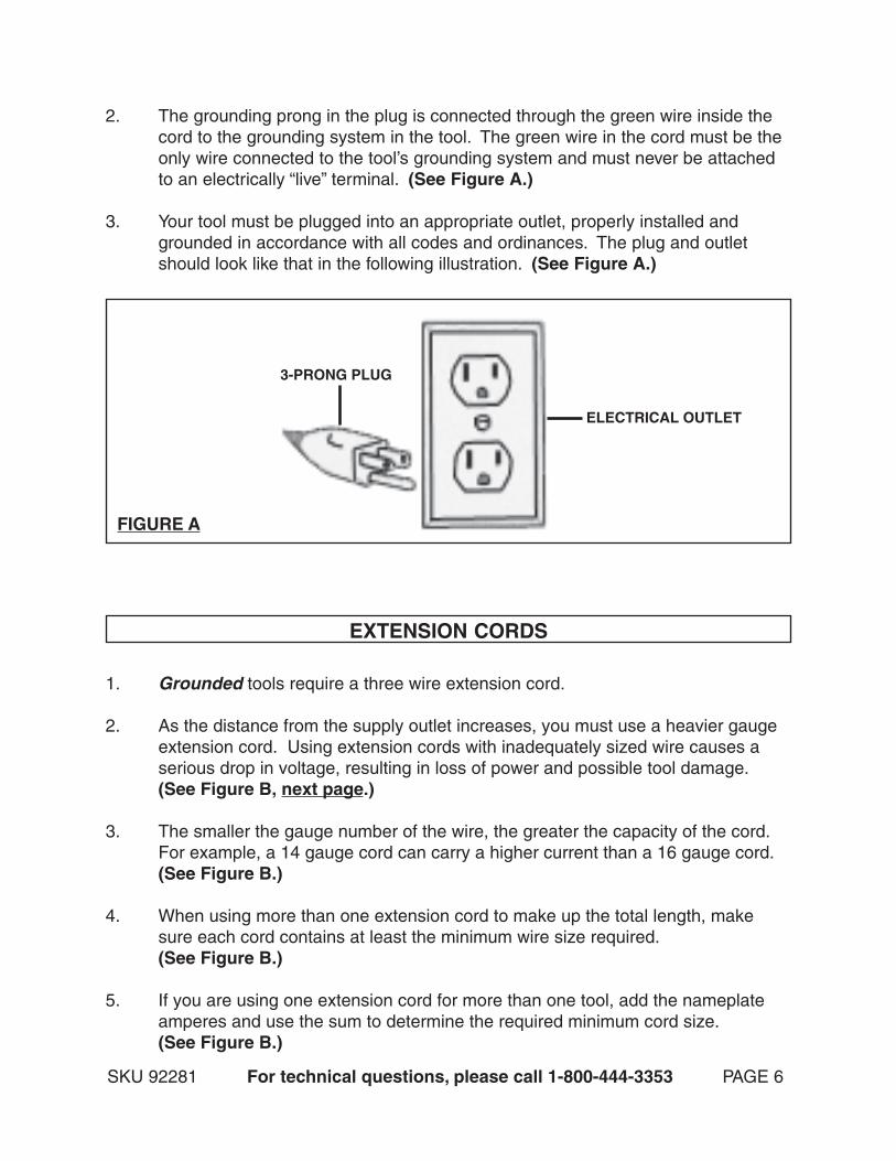
2. The grounding prong in the plug is connected through the green wire inside thecord to the grounding system in the tool. The green wire in the cord must be theonly wire connected to the tool’s grounding system and must never be attachedto an electrically “live” terminal. (See Figure A.)
3. Your tool must be plugged into an appropriate outlet, properly installed andgrounded in accordance with all codes and ordinances. The plug and outletshould look like that in the following illustration. (See Figure A.)
FIGURE A
3-PRONG PLUG
ELECTRICAL OUTLET
EXTENSION CORDS
1. Grounded tools require a three wire extension cord.
2. As the distance from the supply outlet increases, you must use a heavier gaugeextension cord. Using extension cords with inadequately sized wire causes aserious drop in voltage, resulting in loss of power and possible tool damage.(See Figure B, next page.)
3. The smaller the gauge number of the wire, the greater the capacity of the cord.For example, a 14 gauge cord can carry a higher current than a 16 gauge cord.(See Figure B.)
4. When using more than one extension cord to make up the total length, makesure each cord contains at least the minimum wire size required.(See Figure B.)
5. If you are using one extension cord for more than one tool, add the nameplateamperes and use the sum to determine the required minimum cord size.(See Figure B.)
SKU 92281 For technical questions, please call 1-800-444-3353 PAGE 6
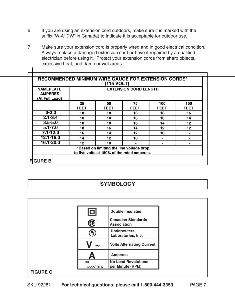
FIGURE B
SKU 92281 For technical questions, please call 1-800-444-3353. PAGE 7
6. If you are using an extension cord outdoors, make sure it is marked with thesuffix “W-A” (“W” in Canada) to indicate it is acceptable for outdoor use.
7. Make sure your extension cord is properly wired and in good electrical condition.Always replace a damaged extension cord or have it repaired by a qualifiedelectrician before using it. Protect your extension cords from sharp objects,excessive heat, and damp or wet areas.
V ~A
no xxxx/min.
No Load Revolutionsper Minute (RPM)
Amperes
Volts Alternating Current
UnderwritersLaboratories, Inc.
Canadian StandardsAssociation
Double Insulated
SYMBOLOGY
FIGURE C
RECOMMENDED MINIMUM WIRE GAUGE FOR EXTENSION CORDS*(115 VOLT)
*Based on limiting the line voltage dropto five volts at 150% of the rated amperes.
SKU 92281 For technical questions, please call 1-800-444-3353. PAGE 8
1. Maintain labels and nameplates on the Chipper/Shredder. These carryimportant information. If unreadable or missing, contact Harbor Freight Tools fora replacement.
2. Use the right product for the right job. There are certain applications forwhich this product was designed. Do not use small equipment, tools, or attach-ments to do the work of larger industrial equipment, tools, or attachments. Donot use this product for a purpose for which it was not intended.
3. WARNING! Beware of the rotating Blades (15). Keeps hands andfingers away from the Hopper (1) and Chute (32). Always use the Feed Stick(59) to push limbs from the Hopper into the Body (13).
4. Check the Hopper Flap (2) for proper opening/closing movement beforeeach use. Do not operate the Chipper/Shredder if the Rubber Board does notmove freely.
5. Make certain that you or anyone in the vicinity stands clear of the Chute(32). Fragments and chips of wood are expelled from the Chute at a very highrate of speed and can cause severe personal injury.
6. Check the Hopper (1), Body (13), and Chute (32) for debris. Before pluggingin the Chipper/Shredder, make sure the Hopper, Body, and Chute are empty.Make a visual check and/or push the end of the Feed Stick (59) around the insideof the Hopper, Body, and Chute. Make sure to remove all debris.
7. Inspect the material before inserting it into the Chipper/Shredder. To avoiddamaging the Blades (15), make sure the material fed into the machine does notcontain metal, rocks, cans, bottles, or any other foreign objects.
8. Use the Chipper/Shredder only for cutting limbs with a maximum diameterof 1-1/4” or smaller.
9. Safely clear a clogged Hopper (1). If the Chipper/Shredder clogs, immediatelyturn off the Power Switch (47) and unplug the machine from its electrical outlet.Only after all moving parts of the machine have stopped moving clear out debris.
SPECIFIC SAFETY RULES
10. Make sure the Chipper/Shredder is located on a flat, level, ground surfacecapable of supporting the weight of the machine, limbs, and any additionaltools and equipment.
11. Do not use the Chipper/Shredder in the rain or in wet conditions.
14. Never leave the Chipper/Shredder unattended when it is plugged into anelectrical outlet. Turn off the machine, and unplug it from its electrical outlet.
SKU 92281 For technical questions, please call 1-800-444-3353. PAGE 9
12. Keep all electrical connections dry and off the ground.
13. Do not handle the Power Switch (47) with wet hands.
15. Allow the Blades (15) to spin up to full speed before feeding limbs intothem. When turning off the Chipper/Shredder, allow the Blades to spin downand stop on their own. Do not press against the Blades with limbs or any otherobjects to stop them.
16. Do not force limbs into the Blades (15) when cutting. Apply moderate pres-sure, allowing the Blades to cut without being forced.
17. Never attempt to remove material stuck in the moving parts of the Chipper/Shredder while it is plugged in.
18. Never stand on the Chipper/Shredder. Serious injury could result if the Chip-per/Shredder is tipped.
19. Industrial applications must follow OSHA requirements.
20. Keep all bystanders and animals safely away while operating the Chipper/Shredder.
21. For your safety: In extreme working conditions, sensors in the Chipper/Shredderwill automatically switch off the Motor to prevent overheating. In this event, turn thePower Switch (47) to its “OFF” position. Unplug the electrical cord and wait fiveminutes or until the Motor has cooled. Clear the machine of all debris. Plug in theelectrical cord and depress the Circuit Breaker. Then, turn the Power Switch to its“ON” position to resume cutting. NEVER attempt to disable the Circuit Breaker.
22. Performance of this machine (if powered by line voltage) may varydepending on variations in local line voltage Extension cord usage mayalso affect machine performance.
23. Wait for sufficient time after shut down before performing any maintenanceon the Chipper/Shredder. The Blades (15) do not stop immediately after turningoff the power and unplugging the machine. Avoid injury by performingmaintenance on the Chipper/Shredder only when all parts are cool to the touch.
24. Avoid entanglement. Feed only one limb at a time into the Hopper (1). Feeding two or more limbs at a time can entangle hands in the limbs, pulling fingers and hands downward into the spinning Blades (15).
26. WARNING! Some dust created by power sanding, sawing, grinding, drill-ing, and other construction activities, contain chemicals known (to the State ofCalifornia) to cause cancer, birth defects or other reproductive harm. Some ex-amples of these chemicals are: lead from lead-based paints, crystalline silica frombricks and cement and other masonry products, arsenic and chromium fromchemically treated lumber. Your risk from these exposures varies, depending onhow often you do this type of work. To reduce your exposure to these chemicals:work in well ventilated areas, and work with approved safety equipment such asthose dust masks that are specially designed to filter out microscopic particles.(California Health & Safety Code 25249.5, et seq.)
27. WARNING! People with pacemakers should consult their physician(s)before using this product. Operation of electrical equipment in close proximity toa heart pacemaker could cause interference or failure of the pacemaker.
28. WARNING! The warnings and cautions discussed in this manual cannotcover all possible conditions and situations that may occur. It must be under-
SKU 92281 For technical questions, please call 1-800-444-3353. PAGE 10
stood by the operator that common sense and caution are factors which cannotbe built into this product, but must be supplied the operator.
SAVE THESE INSTRUCTIONS
25. WARNING! To avoid personal injury or death, NEVER attempt to alteror disable the Safety Shut-Off Switch (42).
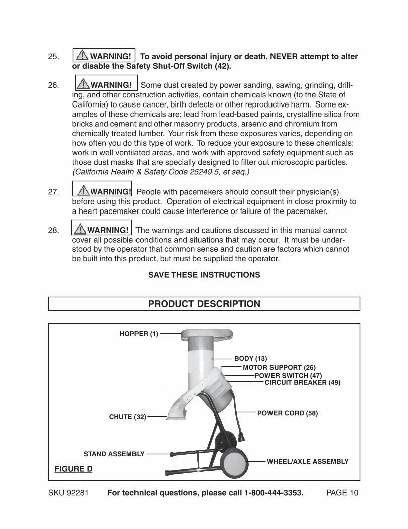
PRODUCT DESCRIPTION
HOPPER (1)
BODY (13)
CHUTE (32)
MOTOR SUPPORT (26)POWER SWITCH (47)
CIRCUIT BREAKER (49)
POWER CORD (58)
WHEEL/AXLE ASSEMBLYSTAND ASSEMBLY
FIGURE D
SKU 92281 For technical questions, please call 1-800-444-3353. PAGE 11
ASSEMBLY INSTRUCTIONS
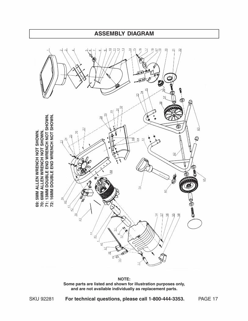
NOTE: For additional information regarding the parts listed in the following pages, referto the Assembly Diagram on page 17.
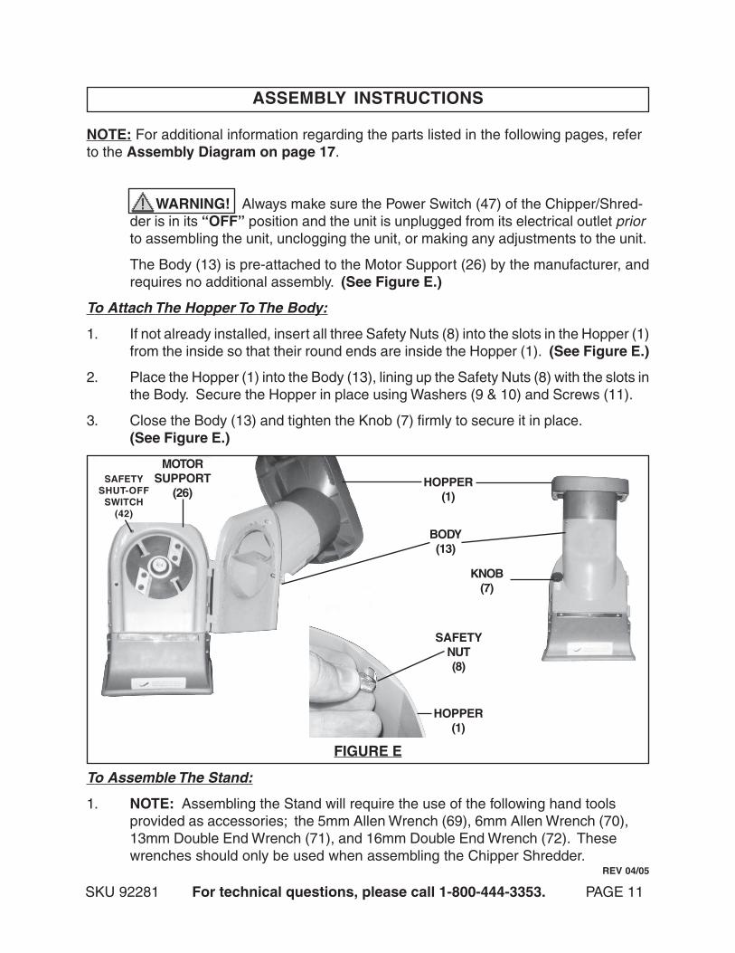
WARNING! Always make sure the Power Switch (47) of the Chipper/Shred-der is in its “OFF” position and the unit is unplugged from its electrical outlet priorto assembling the unit, unclogging the unit, or making any adjustments to the unit.
The Body (13) is pre-attached to the Motor Support (26) by the manufacturer, andrequires no additional assembly. (See Figure E.)
To Attach The Hopper To The Body:
1. If not already installed, insert all three Safety Nuts (8) into the slots in the Hopper (1)from the inside so that their round ends are inside the Hopper (1). (See Figure E.)
2. Place the Hopper (1) into the Body (13), lining up the Safety Nuts (8) with the slots inthe Body. Secure the Hopper in place using Washers (9 & 10) and Screws (11).
3. Close the Body (13) and tighten the Knob (7) firmly to secure it in place.(See Figure E.)
To Assemble The Stand:
1. NOTE: Assembling the Stand will require the use of the following hand toolsprovided as accessories; the 5mm Allen Wrench (69), 6mm Allen Wrench (70),13mm Double End Wrench (71), and 16mm Double End Wrench (72). Thesewrenches should only be used when assembling the Chipper Shredder.
BODY(13)
HOPPER(1)
MOTORSUPPORT
(26)
KNOB(7)
FIGURE E
SAFETYSHUT-OFF
SWITCH(42)
HOPPER(1)
SAFETYNUT(8)
REV 04/05
SKU 92281 For technical questions, please call 1-800-444-3353. PAGE 12
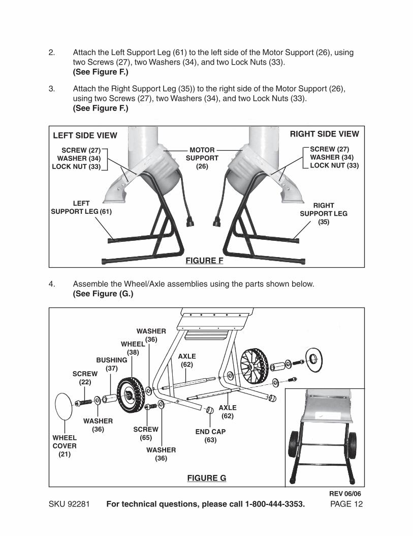
3. Attach the Right Support Leg (35)) to the right side of the Motor Support (26),using two Screws (27), two Washers (34), and two Lock Nuts (33).(See Figure F.)
2. Attach the Left Support Leg (61) to the left side of the Motor Support (26), usingtwo Screws (27), two Washers (34), and two Lock Nuts (33).(See Figure F.)
LEFT SIDE VIEW RIGHT SIDE VIEW
RIGHTSUPPORT LEG
(35)
LEFTSUPPORT LEG (61)
MOTORSUPPORT
(26)
SCREW (27)WASHER (34)
LOCK NUT (33)
SCREW (27)WASHER (34)LOCK NUT (33)
FIGURE F
4. Assemble the Wheel/Axle assemblies using the parts shown below.(See Figure (G.)
WHEELCOVER
(21)
SCREW(22)
WASHER(36)
BUSHING(37)
WHEEL(38)
WASHER(36)
SCREW(65)
WASHER(36)
AXLE(62)
AXLE(62)
END CAP(63)
FIGURE G
REV 06/06
SKU 92281 For technical questions, please call 1-800-444-3353. PAGE 13
OPERATING INSTRUCTIONS
1. WARNING! Use safety equipment. Always wear ANSI approved safetyimpact glasses under an ANSI approved full face shield, ANSI approved hearingand breathing protection, heavy duty work gloves, and nonskid safety shoes andwork pants and work shirt.
2. Make sure to position the Chipper/Shredder on a flat, level, dry ground surface.Position the machine so that the Chute (32) is pointed in a safe direction, at least25 feet from any people, animals, or objects. Then, chock both Wheels (38) ofthe machine with scrap branches or rocks to keep the unit from moving.
3. Connect an appropriate extension cord (not included) to the Power Cord Plug(58), and plug the extension cord into the nearest 115 volt, grounded, electricaloutlet. (See Figure H, next page.)
4. Turn the Power Switch (47) to its “ON” position, and allow the Blades (15) tospin up to full speed. (See Figure H.)
5. Branches cannot be more than 1-1/4” in diameter. Do not attempt to forcelarger branches into the Chipper/Shredder.
6. Do not force the Chipper/Shredder. Let the natural suction process take in thematerial to be cut. Always stand clear and to the side of the Chute (32).(See Figure H.)
7. Without putting your hands into the Hopper (1), slowly drop the material in (onebranch at a time). The machine will pull it in automatically.
8. WARNING! Never use your hands to feed material into the Hopper (1).Always use the Feed Stick (59). (See Figure H.)
9. Should the Chipper/Shredder jam while in use, immediately turn the PowerSwitch (47) to its “OFF” position. Unplug the Power Cord (58). Loosen theKnob (7), and open the Body (13) to expose the Blades (15). Clear the jam.Close the Body, and retighten the Knob. Then plug the Power Cord into itsextension cord, and turn the Power Switch to its “ON” position to resume cutting.(See Figures E and H.)
10. In extreme working conditions sensors in the Chipper/Shredder will automaticallyswitch off the Motor to prevent overheating. In this event, turn the Power Switch(47) to its “OFF” position and unplug the machine from its electrical supply. Waitfive minutes or until the Motor has cooled. Clear the machine of all debris. De-press the Circuit Breaker (49). Then, plug the machine into its electrical supply,
and turn the Power Switch to its “ON” position to resume cutting.NEVER attempt to disable the Circuit Breaker. (See Figure H.)
11. NOTE: The Motor is equipped with a Safety Shut-Off Switch (42) located on thetop portion of the Motor Support (26). Should the Motor not restart, check tomake sure the Body (13) is firmly secured to the Motor Support. If necessary,retighten the Knob (7) to ensure a solid connection between the Body and MotorSupport. (See Figure E.)
12. When finished using the Chipper/Shredder, turn the Power Switch (47) to its“OFF” position. Unplug the Power Cord (58) from its extension cord. Then,unplug the extension cord from its electrical outlet. (See Figure H.)
13. Wait until all moving parts on the Chipper/Shredder have stopped moving. Thenopen the unit and clean out the Hopper (1), Body (13), Motor Support (26), andChute (32). (See Figure H.)
14. Make sure to store the Chipper/Shredder in a clean, dry, safe location out ofreach of children and other unauthorized people.
SKU 92281 For technical questions, please call 1-800-444-3353. PAGE 14
FIGURE H
HOPPER (1)
BODY (13)
FEED STICK (59)
POWERSWITCH
(47)CIRCUIT
BREAKER(49)
POWERCORD
(58)
MOTORSUPPORT
(26)
CHUTE(32)
INSPECTION, MAINTENANCE, AND CLEANING
1. WARNING! Make sure the Power Switch (47) of the Chipper/Shredder is inits “OFF” position and that the machine is unplugged from its electrical outletbefore performing any inspection, maintenance, or cleaning procedures.
2. Before each use, inspect the general condition of the Chipper/Shredder. Checkfor loose screws, misalignment or binding of moving parts, damaged electricalwiring, jammed Blades (15), and any other condition that may affect its safeoperation. If abnormal noise or vibration occurs, have the problem correctedbefore further use. Do not use damaged equipment.
3. Before and after each use, open the unit and clean out the Hopper (1), Body(13), Motor Support (26), and Chute (32).
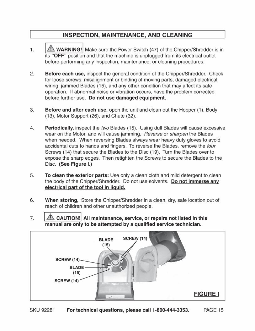
4. Periodically, inspect the two Blades (15). Using dull Blades will cause excessivewear on the Motor, and will cause jamming. Reverse or sharpen the Bladeswhen needed. When reversing Blades always wear heavy duty gloves to avoidaccidental cuts to hands and fingers. To reverse the Blades, remove the fourScrews (14) that secure the Blades to the Disc (19). Turn the Blades over toexpose the sharp edges. Then retighten the Screws to secure the Blades to theDisc. (See Figure I.)
6. When storing, Store the Chipper/Shredder in a clean, dry, safe location out ofreach of children and other unauthorized people.
7. CAUTION! All maintenance, service, or repairs not listed in thismanual are only to be attempted by a qualified service technician.
5. To clean the exterior parts: Use only a clean cloth and mild detergent to cleanthe body of the Chipper/Shredder. Do not use solvents. Do not immerse anyelectrical part of the tool in liquid.
SKU 92281 For technical questions, please call 1-800-444-3353. PAGE 15
BLADE(15)
BLADE(15)
SCREW (14)
SCREW (14)
SCREW (14)
FIGURE I
PARTS LIST
SKU 92281 For technical questions, please call 1-800-444-3353. PAGE 16
NOTE:Some parts are listed and shown for illustration purposes only,
and are not available individually as replacement parts.
PLEASE READ THE FOLLOWING CAREFULLY
THE MANUFACTURER AND/OR DISTRIBUTOR HAS PROVIDED THE PARTS LIST AND ASSEMBLYDIAGRAM IN THIS MANUAL AS A REFERENCE TOOL ONLY. NEITHER THE MANUFACTURER ORDISTRIBUTOR MAKES ANY REPRESENTATION OR WARRANTY OF ANY KIND TO THE BUYER THATHE OR SHE IS QUALIFIED TO MAKE ANY REPAIRS TO THE PRODUCT, OR THAT HE OR SHE ISQUALIFIED TO REPLACE ANY PARTS OF THE PRODUCT. IN FACT, THE MANUFACTURER AND/ORDISTRIBUTOR EXPRESSLY STATES THAT ALL REPAIRS AND PARTS REPLACEMENTS SHOULD BEUNDERTAKEN BY CERTIFIED AND LICENSED TECHNICIANS, AND NOT BY THE BUYER. THE BUYERASSUMES ALL RISK AND LIABILITY ARISING OUT OF HIS OR HER REPAIRS TO THE ORIGINALPRODUCT OR REPLACEMENT PARTS THERETO, OR ARISING OUT OF HIS OR HER INSTALLATIONOF REPLACEMENT PARTS THERETO.
Part # Description Q ty. Part # Description Q ty. 1 Hopper 1 37 Bushing 2 2 Hopper F lap 1 38 W heel 2 3 P ress Board 1 39 Screw 7 4 Screw 7 40 W asher 3 5 Cover 1 41 Sw itch Shelf 1 6 Nut 1 42 Safety Shut-O ff Sw itch 1 7 Knob 1 43 W ire A 2 8 Safety Nut 3 44 M otor Assem bly 1 9 W asher 3 45 Covering 1 10 W asher 11 46 W ire B 2 11 Screw 3 47 Power Sw itch 1 12 Bolt 1 48 W ire D 1 13 Body 1 49 C ircuit B reaker 1 14 Screw 4 50 Nut 1 15 B lade 2 51 Capacitor 1 16 Bolt 1 52 Cable F ix 1 17 Spring W asher 1 53 P rotect Tube 1 18 F ix Board 1 54 M otor Housing 1 19 D isc 1 55 Screw 3 20 D isc Base 1 56 Spring W asher 3 21 W heel Cover 2 57 W asher 3 22 Screw 2 58 Power Cord 1 23 Screw 4 59 Feed S tick 1 24 W asher 4 60 B race 1 25 W asher 4 61 Left Support Leg 1 26 M otor Support 1 62 Axle 2 27 Screw 4 63 End Cap 2 28 W asher 4 64 Sm all R ivet 3 29 Safety Screw 4 65 Screw 2 30 W asher 4 66 S teel Pad 1 31 Lock Nut 4 67 W asher 1 32 Chute 1 68 W asher 1 33 Lock Nut 4 69 5m m A llen W rench 1 34 W asher 8 70 6m m A llen W rench 1 35 R ight Support Leg 1 71 13m m Double End W rench 1 36 W asher 2 72 16m m Double End W rench 1
REV 06/06
REV 06/06
ASSEMBLY DIAGRAM
SKU 92281 For technical questions, please call 1-800-444-3353. PAGE 17
NOTE:Some parts are listed and shown for illustration purposes only,
and are not available individually as replacement parts.
69:
5MM
AL
LE
N W
RE
NC
H N
OT
SH
OW
N.
70:
6MM
AL
LE
N W
RE
NC
H N
OT
SH
OW
N.
71:
13M
M D
OU
BL
E E
ND
WR
EN
CH
NO
T S
HO
WN
.72
: 16
MM
DO
UB
LE
EN
D W
RE
NC
H N
OT
SH
OW
N.
WIRING DIAGRAM
SKU 92281 For technical questions, please call 1-800-444-3353. PAGE 18