NFPA 253 Standard Method of Test for Critical Radiant Flux of Floor Covering Systems Using a Radiant Heat Energy Source 1995 Edition National Fire Protection Association, 1 Batterymarch Park, PO Box 9101, Quincy, MA 02269-9101 An International Codes and Standards Organization
Transcript
NFPA 253Standard Method of Test
for Critical Radiant Fluxof Floor Covering Systems
Using a Radiant HeatEnergy Source
1995 Edition
National Fire Protection Association, 1 Batterymarch Park, PO Box 9101, Quincy, MA 02269-9101An International Codes and Standards Organization
Copyright National Fire Protection Association, Inc.One Batterymarch ParkQuincy, Massachusetts 02269
IMPORTANT NOTICE ABOUT THIS DOCUMENT
NFPA codes, standards, recommended practices, and guides, of which the document contained herein is one, aredeveloped through a consensus standards development process approved by the American National Standards Institute.This process brings together volunteers representing varied viewpoints and interests to achieve consensus on fire and othersafety issues. While the NFPA administers the process and establishes rules to promote fairness in the development ofconsensus, it does not independently test, evaluate, or verify the accuracy of any information or the soundness of anyjudgments contained in its codes and standards.
The NFPA disclaims liability for any personal injury, property or other damages of any nature whatsoever, whetherspecial, indirect, consequential or compensatory, directly or indirectly resulting from the publication, use of, or relianceon this document. The NFPA also makes no guaranty or warranty as to the accuracy or completeness of any informationpublished herein.
In issuing and making this document available, the NFPA is not undertaking to render professional or other services foror on behalf of any person or entity. Nor is the NFPA undertaking to perform any duty owed by any person or entity tosomeone else. Anyone using this document should rely on his or her own independent judgment or, as appropriate, seekthe advice of a competent professional in determining the exercise of reasonable care in any given circumstances.
The NFPA has no power, nor does it undertake, to police or enforce compliance with the contents of this document.Nor does the NFPA list, certify, test or inspect products, designs, or installations for compliance with this document. Anycertification or other statement of compliance with the requirements of this document shall not be attributable to theNFPA and is solely the responsibility of the certifier or maker of the statement.
NOTICES
All questions or other communications relating to this document and all requests for information on NFPA proceduresgoverning its codes and standards development process, including information on the procedures for requesting FormalInterpretations, for proposing Tentative Interim Amendments, and for proposing revisions to NFPA documents duringregular revision cycles, should be sent to NFPA headquarters, addressed to the attention of the Secretary, StandardsCouncil, National Fire Protection Association, 1 Batterymarch Park, P.O. Box 9101, Quincy, MA 02269-9101.
Users of this document should be aware that this document may be amended from time to time through the issuance ofTentative Interim Amendments, and that an official NFPA document at any point in time consists of the current edition ofthe document together with any Tentative Interim Amendments then in effect. In order to determine whether thisdocument is the current edition and whether it has been amended through the issuance of Tentative InterimAmendments, consult appropriate NFPA publications such as the National Fire Codes Subscription Service, visit the NFPAwebsite at www.nfpa.org, or contact the NFPA at the address listed above.
A statement, written or oral, that is not processed in accordance with Section 5 of the Regulations Governing CommitteeProjects shall not be considered the official position of NFPA or any of its Committees and shall not be considered to be,nor be relied upon as, a Formal Interpretation.
The NFPA does not take any position with respect to the validity of any patent rights asserted in connection with anyitems which are mentioned in or are the subject of this document, and the NFPA disclaims liability for the infringement ofany patent resulting from the use of or reliance on this document. Users of this document are expressly advised thatdetermination of the validity of any such patent rights, and the risk of infringement of such rights, is entirely their ownresponsibility.
Users of this document should consult applicable federal, state, and local laws and regulations. NFPA does not, by thepublication of this document, intend to urge action that is not in compliance with applicable laws, and this document maynot be construed as doing so.
Licensing Policy
This document is copyrighted by the National Fire Protection Association (NFPA). By making this document availablefor use and adoption by public authorities and others, the NFPA does not waive any rights in copyright to this document.
1. Adoption by Reference—Public authorities and others are urged to reference this document in laws, ordinances,regulations, administrative orders, or similar instruments. Any deletions, additions, and changes desired by the adoptingauthority must be noted separately. Those using this method are requested to notify the NFPA (Attention: Secretary,Standards Council) in writing of such use. The term "adoption by reference" means the citing of title and publishinginformation only.
2. Adoption by Transcription—A. Public authorities with lawmaking or rule-making powers only, upon written notice tothe NFPA (Attention: Secretary, Standards Council), will be granted a royalty-free license to print and republish thisdocument in whole or in part, with changes and additions, if any, noted separately, in laws, ordinances, regulations,administrative orders, or similar instruments having the force of law, provided that: (1) due notice of NFPA's copyright iscontained in each law and in each copy thereof; and (2) that such printing and republication is limited to numberssufficient to satisfy the jurisdiction's lawmaking or rule-making process. B. Once this NFPA Code or Standard has beenadopted into law, all printings of this document by public authorities with lawmaking or rule-making powers or any otherpersons desiring to reproduce this document or its contents as adopted by the jurisdiction in whole or in part, in any form,upon written request to NFPA (Attention: Secretary, Standards Council), will be granted a nonexclusive license to print,republish, and vend this document in whole or in part, with changes and additions, if any, noted separately, provided thatdue notice of NFPA's copyright is contained in each copy. Such license shall be granted only upon agreement to pay NFPAa royalty. This royalty is required to provide funds for the research and development necessary to continue the work ofNFPA and its volunteers in continually updating and revising NFPA standards. Under certain circumstances, publicauthorities with lawmaking or rule-making powers may apply for and may receive a special royalty where the public interestwill be served thereby.
3. Scope of License Grant—The terms and conditions set forth above do not extend to the index of this document.
(For further explanation, see the Policy Concerning the Adoption, Printing, and Publication of NFPA Documents,which is available upon request from the NFPA.)
This edition of NFPA 253, Standard Method of Test for Critical Radiant Flux of Floor CoveringSystems Using a Radiant Heat Energy Source, was prepared by the Technical Committee on FireTests and acted on by the National Fire Protection Association, Inc., at its Annual Meetingheld May 22-25, 1995, in Denver, CO. It was issued by the Standards Council on July 21, 1995,with an effective date of August 11, 1995, and supersedes all previous editions.
The 1995 edition of this document has been approved by the American National StandardsInstitute.
Origin and Development of NFPA 253
Experience suggests that during the early stages of a fire, floor covering systems seldomhave acted as a fire spread medium. However, in a few fires involving multiple occupancybuildings, the floor covering materials in corridors were primarily responsible for fire spreadover a considerable distance. This caused grave concern and pointed to the need for a realis-tic test to evaluate the flame spread of floor covering systems.
The flooring radiant panel test had its inception with the Armstrong Cork Company in1966. In 1972, conceptualization of critical radiant flux (W/cm2 at extinguishment) as a mea-sure of flame spread hazard was underway at the National Bureau of Standards. It was deter-mined in the course of NBS work on model corridor fire tests that the radiant energy levelsincident on the floor covering had a considerable influence on whether or not flaming com-bustion would propagate. Accordingly, it was natural to apply the critical radiant flux concept,and, in 1973, the National Bureau of Standards prepared a draft of the flooring radiant paneltest.
In 1975, the Technical Committee on Fire Tests began its evaluation of the proposed testmethods, which culminated in the adoption of this test as an official NFPA standard in May1978. The standard was revised in 1984 and 1990.
The 1995 edition includes significant improvements based on work conducted by NIST andthe carpet industry. These findings improve the overall application of the standard and pro-vide measured improvement in test precision. Other changes include a new pilot burner andreduction of the variation in the airflow through the chamber, which reduces the variabilityof data. Revisions also were made to eliminate “permissive” language. These revisions createcloser harmony with ASTM E648, Standard Test Method for Critical Radiant Flux of Floor-CoveringSystems Using a Radiant Heat Energy Source.
253–2 CRITICAL RADIANT FLUX OF FLOOR COVERING SYSTEMS USING A RADIANT HEAT ENERGY SOURCE
199
Technical Committee on Fire Tests
Jesse J. Beitel, Chair Hughes Assoc. Inc., MD
Peter J. Barbadoro, Westinghouse Savannah River Co., SCApril L. Berkol, ITT Sheraton Corp., MA
Rep. American Hotel & Motel Assn.John A. Blair, The DuPont Co., DE
Rep. Society of the Plastics IndustryWilliam P. Chien, State of NY Dept. of Fire Prevention & Con-trol, NYWilliam E. Fitch, Omega Point Laboratories Inc., TXThomas W. Fritz, Armstrong World Industries Inc., PAJeffrey E. Gould, Factory Mutual Research Corp., MAAlfred J. Hogan, Reedy Creek Improvement District, FL
Rep. Fire Marshals Assn. of North AmericaWayne D. Holmes, HSB Professional Loss Control Inc., PAKarl D. Houser, Gypsum Assn., DCMarc L. Janssens, American Forest & Paper Assn., DCJames R. Lawson, U.S. Nat’l Inst. of Standards and Technolo-gy, MD
Gerald E. Lingenfelter, American Insurance Services Group Inc., NYGeorge E. Meyer, Warnock Hersey Int’l Inc., CAJohn W. Michener, Milliken Research Corp., SC
Rep. American Textile Mfrs. Inst. Inc.James A. Milke, University of Maryland, MDJames C. Norris, Union Carbide, PALeon Przybyla, Underwriters Laboratories Inc., ILSivon C. Reznikoff, Arizona State University, AZJohn Roberts, Underwriters Laboratories of Canada, ONHoward Stacy, Southwest Research Inst., TXHerman Stone, General Foam, PAT. Hugh Talley, Hugh Talley Co., TN
Rep. Upholstered Furniture Action CouncilRichard P. Thornberry, The Code Consortium, Inc., CARobert J. Wills, American Iron & Steel Inst., ALPeter J. Gore Willse, Industrial Risk Insurers, CT
Alternates
Peter H. Billing, American Forest & Paper Assn., FL(Alt. to M. L. Janssens)
Delbert F. Boring, Jr., American Iron & Steel Inst., OH(Alt. to R. J. Wills)
Tony Crimi, Underwriters Laboratories of Canada, ON(Alt. to J. Roberts)
Philip J. DiNenno, Hughes Assoc. Inc., MD(Alt. to J. J. Beitel)
Richard D. Gottwald, Society of the Plastics Industry, DC(Alt. to J. A. Blair)
Arthur J. Parker, Southwest Research Inst., TX(Alt. to H. Stacy)
R. Joseph Pearson, Inchcape Testing Services, Warnock Her-sey Int’l Inc., NY
(Alt. to G. E. Meyer)
William A. Thornberg, Industrial Risk Insurers, CT
(Alt. to P. J. G. Willse)
James J. Urban, Underwriters Laboratories Inc., IL
(Alt. to L. Przybyla)
Kay M. Villa, American Textile Mfrs. Inst. Inc., DC
(Alt. to J. W. Michener)
Joe Ziolkowski, American Furniture Mfrs. Assoc., NC
(Alt. to T. H. Talley)
Nonvoting
A. J. Bartosic, Rohm & Haas Co., PA Herman H. Spaeth, CA(Member Emeritus)
Walter P. Sterling, NFPA Staff Liaison
This list represents the membership at the time the Committee was balloted on the text of this edition. Since that time, changes inmembership may have occurred. A key to classifications is found at the back of this document.
NOTE: Membership on a committee shall not in and of itself constitute an endorsement of the Association or anydocument developed by the committee on which the member serves.
Committee Scope: This Committee shall have primary responsibility for documents on fire testing procedureswhen such standards are not available; for reviewing existing fire test standards and recommending appropriate ac-tion to NFPA; for recommending the application of and advising on the interpretation of acceptable test standardsfor fire problems of concern to NFPA technical committees and members; and for acting in a liaison capacity be-tween NFPA and the committees of other organizations writing fire test standards. This Committee does not coverfire tests that are used to evaluate extinguishing agents, devices, or systems.
253–4 CRITICAL RADIANT FLUX OF FLOOR COVERING SYSTEMS USING A RADIANT HEAT ENERGY SOURCE
NFPA 253
Standard Method of Test for
Critical Radiant Flux of FloorCovering Systems
Using a Radiant Heat Energy Source
1995 Edition
NOTICE: An asterisk (*) following the number or letter des-ignating a paragraph indicates that explanatory material onthe paragraph can be found in Appendix A.
Information on referenced publications can be found inChapter 9 and Appendix E.
Chapter 1 General
1-1 Scope.
1-1.1 This fire test response standard describes a procedurefor measuring critical radiant flux behavior of horizontallymounted floor covering systems exposed to a flaming ignitionsource in a graded, radiant heat energy environment within atest chamber. The specimen can be mounted over underlay-ment or over a simulated concrete structural floor, bonded toa simulated structural floor, or otherwise mounted in a typicaland representative way.
1-1.2 This fire test response standard measures the criticalradiant flux at flameout. It provides a basis for estimating oneaspect of fire exposure behavior for floor covering systems.
The imposed radiant flux simulates the thermal radiation lev-els likely to impinge on the floors of a building whose upper sur-faces are heated by flames or hot gases, or both, from a fullydeveloped fire in an adjacent room or compartment. The stan-dard was developed to simulate an important fire exposure com-ponent in fires that develop in corridors or exitways of buildingsand is not intended for routine use in estimating flame spreadbehavior of floor covering in building areas other than corridorsor exitways. Appendix F provides information on the properapplication and interpretation of the results of this test.
1-1.3 The values stated in SI units are to be regarded as thestandard.
1-1.4 This standard shall be used to measure and describe theresponse of materials, products, or assemblies to heat andflame under controlled conditions and shall not be used todescribe or appraise the fire hazard or fire risk of materials,products, or assemblies under actual fire conditions. However,the results of the test shall be permitted to be used as elementsof a fire hazard assessment or a fire risk assessment that takesinto account all factors that are pertinent to an assessment ofthe fire hazard or fire risk of a particular end use.
1-1.5 This standard does not purport to address all safety prob-lems associated with its use. It is the responsibility of the user ofthis standard to establish appropriate safety and health practices
and to determine the applicability of regulatory limitations priorto use. Specific safety precautions are provided in Chapter 4.
1-2 Significance and Use.
1-2.1 This fire test response standard is designed to provide abasis for estimating one aspect of the fire exposure behaviorof a floor covering system installed in a building corridor. Thetest environment simulates conditions that have beenobserved and defined in full-scale corridor experiments.
1-2.2 The test is suitable for regulatory statutes, specificationacceptance, design purposes, or development and research.
1-2.3 The fundamental assumption inherent in the test is that“critical radiant flux” is one measure of the sensitivity to flamespread of floor covering systems located in a building corridor.
1-2.4 The test is applicable to floor covering system specimensthat follow or simulate accepted installation practice. Tests onthe individual elements of a floor system are not valid for eval-uation of the flooring system.
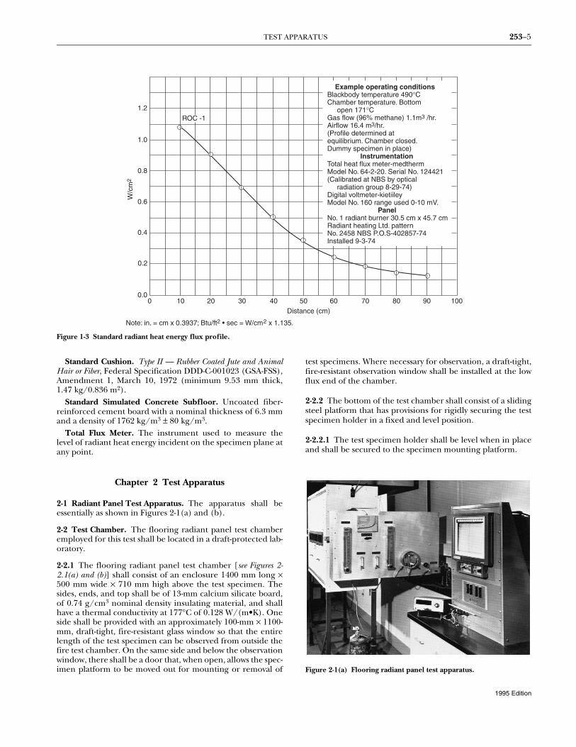
1-3 Summary of Test Method. The basic elements of the testchamber include an air-gas-fueled radiant heat energy panelinclined at 30 degrees to and directed at a horizontally mountedfloor covering system specimen. The radiant panel generates aradiant energy flux distribution along the 100-cm length of thetest specimen from a nominal maximum of 1.0 W/cm2 to a min-imum of 0.1 W/cm2. The test is initiated by open-flame ignitionfrom a pilot burner. The distance burned to flameout is con-verted to W/cm2 from the flux profile graph shown in Figure 1-3 and is reported as critical radiant flux W/cm2.
1-4 Definitions.
Blackbody Temperature. The temperature of a perfectradiator; a surface with an emissivity of unity and, therefore, areflectivity of zero (0).
Corridor. An enclosed space connecting a room or com-partment with an exit. The corridor includes normal exten-sions, such as lobbies and other enlarged spaces.
Critical Radiant Flux. The level of incident radiant heatenergy on the floor covering system at the most distant flame-out point. It is reported as W/cm2.
Flameout. The time at which the last vestige of flame orglow disappears from the surface of the test specimen, fre-quently accompanied by a final puff of smoke; time zero (0) isthe time at which the specimen is moved into the chamberand the door is closed. (See Section 6-3.)
Floor Covering. A separate or secondary surface appliedover a flooring and including underlayment materials, carpet-ing, resilients, and coating systems.
Floor Covering System. A flooring or a combination offlooring and floor covering.
Flooring. A primary floor surface or a final floor surface.
Flux Profile. The curve of incident radiant heat energy onthe specimen plane relative to the distance from the point ofinitiation of flaming ignition (i.e., 0 cm).
Shall. Indicates a mandatory requirement.
Should. Indicates a recommendation or that which isadvised but not required.
1995 Edition
TEST APPARATUS 253–5
Figure 1-3 Standard radiant heat energy flux profile.
Standard Cushion. Type II — Rubber Coated Jute and AnimalHair or Fiber, Federal Specification DDD-C-001023 (GSA-FSS),Amendment 1, March 10, 1972 (minimum 9.53 mm thick,1.47 kg/0.836 m2).
Standard Simulated Concrete Subfloor. Uncoated fiber-reinforced cement board with a nominal thickness of 6.3 mmand a density of 1762 kg/m3 ± 80 kg/m3.
Total Flux Meter. The instrument used to measure thelevel of radiant heat energy incident on the specimen plane atany point.
Chapter 2 Test Apparatus
2-1 Radiant Panel Test Apparatus. The apparatus shall beessentially as shown in Figures 2-1(a) and (b).
2-2 Test Chamber. The flooring radiant panel test chamberemployed for this test shall be located in a draft-protected lab-oratory.
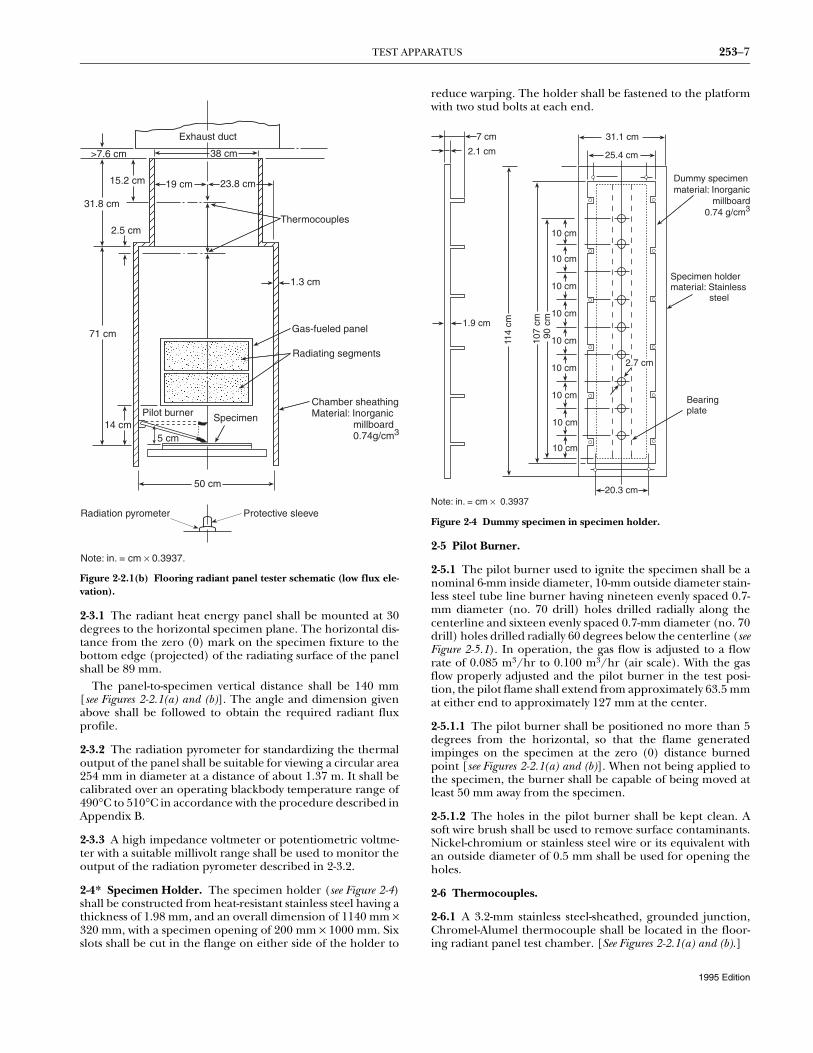
2-2.1 The flooring radiant panel test chamber [see Figures 2-2.1(a) and (b)] shall consist of an enclosure 1400 mm long ×500 mm wide × 710 mm high above the test specimen. Thesides, ends, and top shall be of 13-mm calcium silicate board,of 0.74 g/cm3 nominal density insulating material, and shallhave a thermal conductivity at 177°C of 0.128 W/(m•K). Oneside shall be provided with an approximately 100-mm × 1100-mm, draft-tight, fire-resistant glass window so that the entirelength of the test specimen can be observed from outside thefire test chamber. On the same side and below the observationwindow, there shall be a door that, when open, allows the spec-imen platform to be moved out for mounting or removal of
test specimens. Where necessary for observation, a draft-tight,fire-resistant observation window shall be installed at the lowflux end of the chamber.
2-2.2 The bottom of the test chamber shall consist of a slidingsteel platform that has provisions for rigidly securing the testspecimen holder in a fixed and level position.
2-2.2.1 The test specimen holder shall be level when in placeand shall be secured to the specimen mounting platform.
Figure 2-1(a) Flooring radiant panel test apparatus.
1.2
1.0
0.8
0.6
0.4
0.2
0.00 10 20 30 40 50 60 70 80 90 100
Distance (cm)
W/c
m2
ROC -1
Example operating conditionsBlackbody temperature 490°CChamber temperature. Bottom open 171°CGas flow (96% methane) 1.1m3 /hr.Airflow 16.4 m3/hr.(Profile determined atequilibrium. Chamber closed.Dummy specimen in place) InstrumentationTotal heat flux meter-medthermModel No. 64-2-20. Serial No. 124421(Calibrated at NBS by optical radiation group 8-29-74)Digital voltmeter-kietiileyModel No. 160 range used 0-10 mV. PanelNo. 1 radiant burner 30.5 cm x 45.7 cmRadiant heating Ltd. patternNo. 2458 NBS P.O.S-402857-74Installed 9-3-74
Note: in. = cm x 0.3937; Btu/ft2 • sec = W/cm2 x 1.135.
1995 Edition
253–6 CRITICAL RADIANT FLUX OF FLOOR COVERING SYSTEMS USING A RADIANT HEAT ENERGY SOURCE
2-2.2.2 The free, or air access, area around the platform shallbe 2580 cm2 to 3225 cm2.
2-2.3 The top of the chamber shall have an exhaust stack withinterior dimensions of 102 mm ± 3 mm wide × 380 mm ± 3 mmdeep × 318 mm ± 3 mm high at the opposite end of the cham-ber from the radiant panel.
2-3 Radiant Heat Energy Source.
(a) The radiant heat energy source shall be a panel con-sisting of a porous refractory material mounted in a cast-ironframe or steel frame and having a radiation surface of 305mm × 457 mm. It shall be capable of operating at tempera-tures up to 816°C.
(b) The panel fuel system shall consist of a venturi-typeaspirator for mixing gas and air at approximately atmo-spheric pressure, a clean, dry air supply capable of providing28.3 NTP m3/hr at 76 mm of water column, and suitableinstrumentation for monitoring and controlling the flow offuel to the panel. The radiant heat energy panel shall be firedby propane, methane, or natural gas.
2-3.1 The radiant heat energy panel shall be mounted at 30degrees to the horizontal specimen plane. The horizontal dis-tance from the zero (0) mark on the specimen fixture to thebottom edge (projected) of the radiating surface of the panelshall be 89 mm.
The panel-to-specimen vertical distance shall be 140 mm[see Figures 2-2.1(a) and (b)]. The angle and dimension givenabove shall be followed to obtain the required radiant fluxprofile.
2-3.2 The radiation pyrometer for standardizing the thermaloutput of the panel shall be suitable for viewing a circular area254 mm in diameter at a distance of about 1.37 m. It shall becalibrated over an operating blackbody temperature range of490°C to 510°C in accordance with the procedure described inAppendix B.
2-3.3 A high impedance voltmeter or potentiometric voltme-ter with a suitable millivolt range shall be used to monitor theoutput of the radiation pyrometer described in 2-3.2.
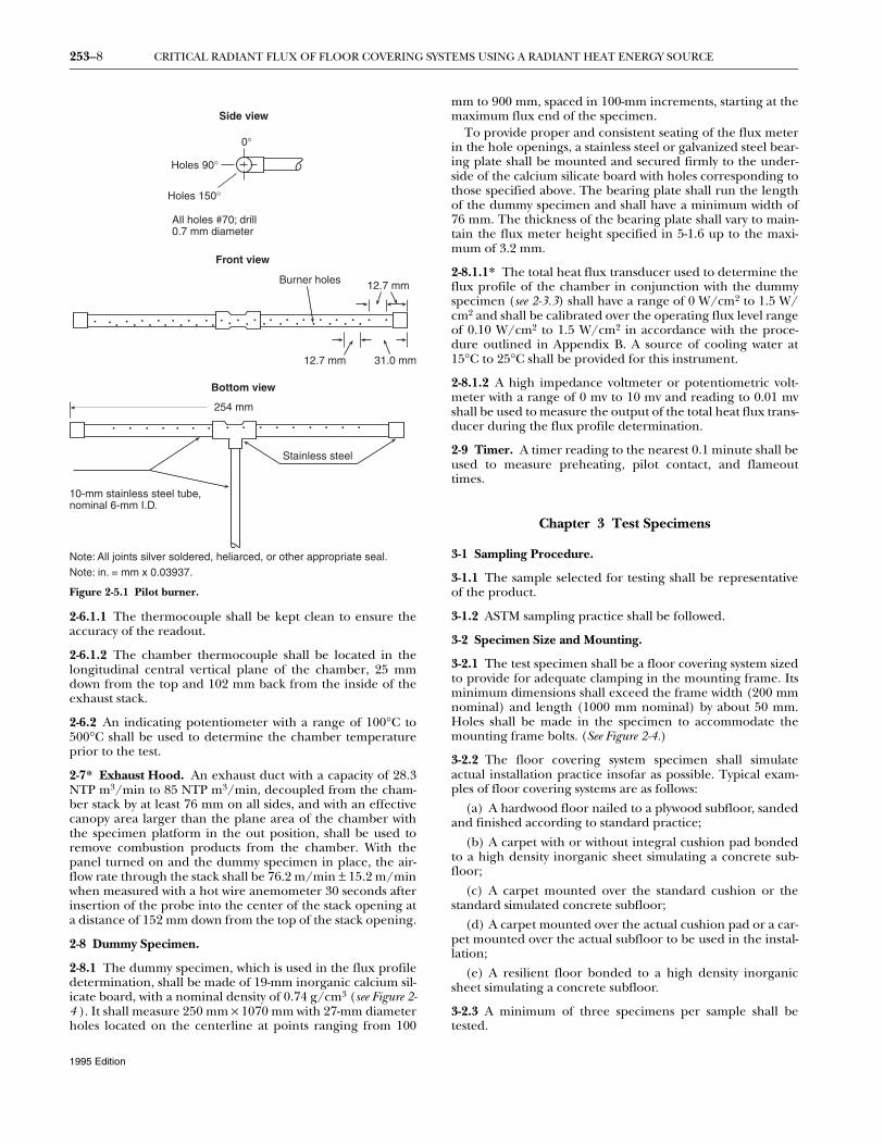
2-4* Specimen Holder. The specimen holder (see Figure 2-4)shall be constructed from heat-resistant stainless steel having athickness of 1.98 mm, and an overall dimension of 1140 mm ×320 mm, with a specimen opening of 200 mm × 1000 mm. Sixslots shall be cut in the flange on either side of the holder to
reduce warping. The holder shall be fastened to the platformwith two stud bolts at each end.
Figure 2-4 Dummy specimen in specimen holder.
2-5 Pilot Burner.
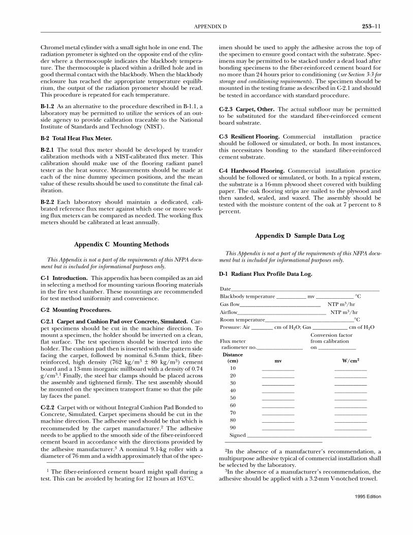
2-5.1 The pilot burner used to ignite the specimen shall be anominal 6-mm inside diameter, 10-mm outside diameter stain-less steel tube line burner having nineteen evenly spaced 0.7-mm diameter (no. 70 drill) holes drilled radially along thecenterline and sixteen evenly spaced 0.7-mm diameter (no. 70drill) holes drilled radially 60 degrees below the centerline (seeFigure 2-5.1). In operation, the gas flow is adjusted to a flowrate of 0.085 m3/hr to 0.100 m3/hr (air scale). With the gasflow properly adjusted and the pilot burner in the test posi-tion, the pilot flame shall extend from approximately 63.5 mmat either end to approximately 127 mm at the center.
2-5.1.1 The pilot burner shall be positioned no more than 5degrees from the horizontal, so that the flame generatedimpinges on the specimen at the zero (0) distance burnedpoint [see Figures 2-2.1(a) and (b)]. When not being applied tothe specimen, the burner shall be capable of being moved atleast 50 mm away from the specimen.
2-5.1.2 The holes in the pilot burner shall be kept clean. Asoft wire brush shall be used to remove surface contaminants.Nickel-chromium or stainless steel wire or its equivalent withan outside diameter of 0.5 mm shall be used for opening theholes.
2-6 Thermocouples.
2-6.1 A 3.2-mm stainless steel-sheathed, grounded junction,Chromel-Alumel thermocouple shall be located in the floor-ing radiant panel test chamber. [See Figures 2-2.1(a) and (b).]
253–8 CRITICAL RADIANT FLUX OF FLOOR COVERING SYSTEMS USING A RADIANT HEAT ENERGY SOURCE
Figure 2-5.1 Pilot burner.
2-6.1.1 The thermocouple shall be kept clean to ensure theaccuracy of the readout.
2-6.1.2 The chamber thermocouple shall be located in thelongitudinal central vertical plane of the chamber, 25 mmdown from the top and 102 mm back from the inside of theexhaust stack.
2-6.2 An indicating potentiometer with a range of 100°C to500°C shall be used to determine the chamber temperatureprior to the test.
2-7* Exhaust Hood. An exhaust duct with a capacity of 28.3NTP m3/min to 85 NTP m3/min, decoupled from the cham-ber stack by at least 76 mm on all sides, and with an effectivecanopy area larger than the plane area of the chamber withthe specimen platform in the out position, shall be used toremove combustion products from the chamber. With thepanel turned on and the dummy specimen in place, the air-flow rate through the stack shall be 76.2 m/min ± 15.2 m/minwhen measured with a hot wire anemometer 30 seconds afterinsertion of the probe into the center of the stack opening ata distance of 152 mm down from the top of the stack opening.
2-8 Dummy Specimen.
2-8.1 The dummy specimen, which is used in the flux profiledetermination, shall be made of 19-mm inorganic calcium sil-icate board, with a nominal density of 0.74 g/cm3 (see Figure 2-4 ). It shall measure 250 mm × 1070 mm with 27-mm diameterholes located on the centerline at points ranging from 100
mm to 900 mm, spaced in 100-mm increments, starting at themaximum flux end of the specimen.
To provide proper and consistent seating of the flux meterin the hole openings, a stainless steel or galvanized steel bear-ing plate shall be mounted and secured firmly to the under-side of the calcium silicate board with holes corresponding tothose specified above. The bearing plate shall run the lengthof the dummy specimen and shall have a minimum width of76 mm. The thickness of the bearing plate shall vary to main-tain the flux meter height specified in 5-1.6 up to the maxi-mum of 3.2 mm.
2-8.1.1* The total heat flux transducer used to determine theflux profile of the chamber in conjunction with the dummyspecimen (see 2-3.3) shall have a range of 0 W/cm2 to 1.5 W/cm2 and shall be calibrated over the operating flux level rangeof 0.10 W/cm2 to 1.5 W/cm2 in accordance with the proce-dure outlined in Appendix B. A source of cooling water at15°C to 25°C shall be provided for this instrument.
2-8.1.2 A high impedance voltmeter or potentiometric volt-meter with a range of 0 mv to 10 mv and reading to 0.01 mvshall be used to measure the output of the total heat flux trans-ducer during the flux profile determination.
2-9 Timer. A timer reading to the nearest 0.1 minute shall beused to measure preheating, pilot contact, and flameouttimes.
Chapter 3 Test Specimens
3-1 Sampling Procedure.
3-1.1 The sample selected for testing shall be representativeof the product.
3-1.2 ASTM sampling practice shall be followed.
3-2 Specimen Size and Mounting.
3-2.1 The test specimen shall be a floor covering system sizedto provide for adequate clamping in the mounting frame. Itsminimum dimensions shall exceed the frame width (200 mmnominal) and length (1000 mm nominal) by about 50 mm.Holes shall be made in the specimen to accommodate themounting frame bolts. (See Figure 2-4.)
3-2.2 The floor covering system specimen shall simulateactual installation practice insofar as possible. Typical exam-ples of floor covering systems are as follows:
(a) A hardwood floor nailed to a plywood subfloor, sandedand finished according to standard practice;
(b) A carpet with or without integral cushion pad bondedto a high density inorganic sheet simulating a concrete sub-floor;
(c) A carpet mounted over the standard cushion or thestandard simulated concrete subfloor;
(d) A carpet mounted over the actual cushion pad or a car-pet mounted over the actual subfloor to be used in the instal-lation;
(e) A resilient floor bonded to a high density inorganicsheet simulating a concrete subfloor.
3-2.3 A minimum of three specimens per sample shall betested.
Front view
Holes 90°
Holes 150°
All holes #70; drill0.7 mm diameter
0°
Side view
• • • • • • • • • •
254 mm
Stainless steel
• • • • • •
10-mm stainless steel tube,nominal 6-mm I.D.
Note: All joints silver soldered, heliarced, or other appropriate seal.
Bottom view
• • • • ••
•• • • • • •• • •
• • • • • • • • • •• • • • • • • ••
12.7 mmBurner holes
12.7 mm 31.0 mm
Note: in. = mm x 0.03937.
1995 Edition
TEST PROCEDURE 253–9
3-3 Specimen Conditioning. Test specimens shall be condi-tioned at 21°C ± 3°C and a relative humidity of 50 percent ± 5percent horizontally or vertically in open racks for optimumair circulation for a minimum of 48 hours; carpet specimensthat have been glued down shall be conditioned for a mini-mum of 96 hours. Conditioning shall be conducted in accor-dance with ASTM E171, Standard Specification for StandardAtmospheres for Conditioning and Testing Flexible Barrier Materials.
Chapter 4 Safety Precautions
4-1 Gas-Air Fuel Explosions. The possibility of a gas-air fuelexplosion in the test chamber shall be recognized. Suitablesafeguards consistent with sound engineering practice shall beinstalled in the panel fuel supply system. Safeguards shallinclude one or more of the following:
(a) A gas feed cutoff activated when the air supply fails;
(b) A fire sensor directed at the panel surface that stopsfuel flow when the panel flame goes out;
(c) A commercial gas water heater or gas-fired furnacepilot burner control thermostatic shutoff that is activatedwhen the gas supply fails, or other suitable approved device.
Safeguards shall be arranged for a manual reset.
4-2 Exhaust System. The exhaust system shall be designedand operated so that the laboratory environment is protectedfrom smoke and gas. Operator exposure to combustion prod-ucts shall be minimized by following sound safety practice.The operator shall ensure that the exhaust system is workingproperly and shall wear appropriate clothing, includinggloves.
Chapter 5 Radiant Heat Energy Flux Profile Standardization
5-1 Procedure.
5-1.1 In a continuing program of tests, the flux profile shall bedetermined at least weekly. Where the time interval betweentests is greater than one week, the flux profile shall be deter-mined at the start of the test series.
5-1.2 The dummy specimen shall be mounted in the mount-ing frame, and the assembly shall be attached to the slidingplatform.
5-1.3 With the sliding platform outside the chamber, the radi-ant panel shall be ignited. The unit shall heat for 11/2 hours.The pilot burner shall be off during this determination. Thefuel mixture shall be adjusted to provide an air-rich flame.Fuel flow shall be set to bring the panel blackbody tempera-ture to about 500°C, and the chamber temperature shall berecorded.
5-1.4 When equilibrium has been established, the specimenplatform shall be moved into the chamber and the door shallbe closed.
5-1.5 The closed chamber shall be allowed to equilibrate for30 minutes.
5-1.6 The radiant heat energy flux level shall be measured atthe 400-mm point with the total flux meter instrumentation.
This shall be accomplished by inserting the flux meter into theopening so that its detecting plane is 1.6 mm to 3.2 mm aboveand parallel to the plane of the dummy specimen and thenreading its output after 30 sec ± 10 sec. If the level is within thelimits specified in 5-1.7, the flux profile determination shall bestarted. Otherwise, the necessary adjustments in panel fuelflow shall be made. Data shall be recorded using the flux pro-file data log format shown in Appendix D, or equivalent.
5-1.7 The test shall be run under chamber operating condi-tions that provide a flux profile as shown in Figure 1-3. Theradiant heat energy incident on the dummy specimen shall beas follows:
(a) Between 0.87 W/cm2 and 0.95 W/cm2 at the 200-mmpoint;
(b) Between 0.48 W/cm2 and 0.52 W/cm2 at the 400-mmpoint; and
(c) Between 0.22 W/cm2 and 0.26 W/cm2 at the 600-mmpoint.
5-1.8 The flux meter shall be inserted into the 100-mm open-ing following the procedure outlined in 5-1.6. The mv outputshall be read at 30 sec ± 10 sec. The same procedure shall berepeated at the 200-mm point. The 300-mm to 900-mm fluxlevels shall be determined in the same manner. Following the900-mm measurement, a reading check shall be made at 400mm. The test chamber is in calibration when it is within thelimits set forth in 5-1.7 and the profile determination is com-pleted. Otherwise, the fuel flow shall be adjusted carefully,allowing 30 minutes for equilibrium, and the procedure shallbe repeated.
5-1.9 The radiant heat energy flux data shall be plotted as afunction of distance along the specimen plane on rectangularcoordinate graph paper. The best smooth curve shall bedrawn carefully through the data points. This curve is hereaf-ter referred to as the flux profile curve.
5-1.10 The open chamber temperature and radiant panelblackbody temperature identified with the standard flux pro-file shall be determined by opening the door and moving thespecimen platform outside the chamber. The chamber shallbe allowed to equilibrate for 30 minutes. The chamber tem-perature and optical pyrometer output that indicate the panelblackbody temperature shall be read and recorded in degreesCelsius. These temperature settings shall be used in subse-quent test work instead of measuring the dummy specimenradiant flux at 200 mm, 400 mm, and 600 mm.
Chapter 6 Test Procedure
6-1 Pretest Heating. With the sliding platform outside thechamber, the radiant panel shall be ignited. The unit shall beallowed to heat for 11/2 hours. A sheet of inorganic millboard,such as calcium silicate, or equivalent, shall be used to coverthe opening when the hinged portion of the front panel isopen and the specimen platform is moved out of the chamber.The millboard shall be used to prevent heating of the speci-men and to protect the operator. The panel blackbody tem-perature and the chamber temperature shall be read. If thesetemperatures are in agreement to within ±5°C of those deter-mined in accordance with 5-1.10, the chamber is ready for use.
1995 Edition
253–10 CRITICAL RADIANT FLUX OF FLOOR COVERING SYSTEMS USING A RADIANT HEAT ENERGY SOURCE
6-2 Sample Mounting. The sample holder shall be invertedon a workbench and the flooring system shall be inserted. Thesteel bar clamps shall be placed across the back of the assemblyand the nuts shall be tightened firmly. The sample holdershall be returned to its upright position, the test surface shallbe cleaned with a vacuum, and the sample holder shall bemounted on the specimen platform. Carpet specimens shallbe brushed to raise the pile to its normal position.
6-3 Ignition of Pilot Burner. The pilot burner shall beignited, keeping it at least 50 mm away from the specimen, thespecimen shall be moved into the chamber, and the door shallbe closed. The timer shall be started. After 5 minutes, thechamber shall be preheated. With the pilot burner on and atleast 50 mm away from the specimen, the pilot burner flameshall be brought into contact with the specimen at the zero (0)mm mark. The pilot burner flame shall remain in contact withthe specimen for 5 minutes. It then shall be removed to a posi-tion at least 50 mm away from the specimen and the pilotburner flame shall be extinguished.
6-4 Flame Propagation of Specimen. If the specimen doesnot propagate flame within 5 minutes following pilot burnerflame application, the test shall be terminated. For specimensthat do propagate flame, the test shall be continued until theflame goes out. Significant phenomena such as melting, blis-tering, and penetration of flame to the substrate shall beobserved and recorded.
6-5 Completion of Test. When the test is completed, thedoor shall be opened and the specimen platform shall bepulled out. The protective inorganic millboard sheet shall beput in place.
6-6 Data Collection and Recording. The distance burnedshall be measured (i.e., the point of farthest advance of theflame front to the nearest 1 mm). The distance to W/cm2 crit-ical radiant heat flux at flameout shall be converted from theflux profile curve. Data shall be recorded using the data logformat shown in Appendix D, or equivalent.
6-7 Removal of Specimen. The specimen and its mountingframe shall be removed from the movable platform.
6-8 Subsequent Testing. The succeeding test shall be startedas soon as the panel blackbody and chamber temperatures areverified (see 5-1.10). The test assembly shall be at room tem-perature prior to start-up.
Chapter 7 Calculations
7-1 General. The mean, standard deviation, and coefficientof variation of the critical radiant flux test data on the threespecimens shall be calculated in accordance with ASTM Man-ual 7, Manual on Quality Control of Materials.
where:S = Estimated standard deviationX = Value of single observationn = Number of observationsX = Arithmetic mean of the set of observationsV = Coefficient of variation.
Chapter 8 Report
8-1 Required Information. The report shall include the fol-lowing:
(a) Description of the floor covering system tested, includ-ing its elements;
(b) Description of the procedure used to assemble thefloor covering system specimen;
(c) Number of specimens tested;(d) Individual values of critical radiant flux;(e) Average critical radiant flux, standard deviation, and
coefficient of variation;(f) Observations of the burning characteristics of the spec-
imen during the testing exposure, such as delamination,melting, sagging, and shrinking.
Chapter 9 Referenced Publications
9-1 The following documents or portions thereof are refer-enced within this standard and shall be considered part of therequirements of this document. The edition indicated foreach reference is the current edition as of the date of theNFPA issuance of this document.
9-1.1 ASTM Publications. American Society for Testing andMaterials, 1916 Race Street, Philadelphia, PA 19103.
ASTM, Manual 7, Manual on Quality Control of Materials.ASTM E171, Standard Specification for Standard Atmospheres for
Conditioning and Testing Flexible Barrier Materials, 1994.
9-1.2 U.S. Government Publication. General Services Admin-istration, 18th and F Streets NW, Washington, DC 20405.
Type II—Rubber Coated Jute and Animal Hair or Fiber, FederalSpecification DDD-C-001023 (GSA-FSS), Amendment 1,March 10, 1972.
Appendix A Explanatory Material
This Appendix is not a part of the requirements of this NFPA doc-ument but is included for informational purposes only.
A-2-4 An acceptable heat-resistant stainless steel is AISI Type300 (UNA-NO8 330) or equivalent.
A-2-7 An acceptable anemometer is an Omega HH-615 HThot-wired anemometer manufactured by Omega EngineeringInc., Stamford, CT.
A-2-8.1.1 An acceptable heat flux transducer is a Schmidt-Boelter-type Medtherm 64-2-20, manufactured by MedthermCorporation, Huntsville, AL.
Appendix B Procedure for Calibration of Apparatus
This Appendix is not a part of the requirements of this NFPA docu-ment but is included for informational purposes only.
B-1 Radiation Pyrometer.
B-1.1 The radiation pyrometer should be calibrated by meansof a conventional blackbody enclosure placed within a furnaceand maintained at uniform temperatures of 490°C, 500°C, and510°C. The blackbody enclosure can consist of a closed
SΣ X2 nX2–( )
n 1–---------------------------------- and V S
X---- 100×==
1995 Edition
APPENDIX D 253–11
Chromel metal cylinder with a small sight hole in one end. Theradiation pyrometer is sighted on the opposite end of the cylin-der where a thermocouple indicates the blackbody tempera-ture. The thermocouple is placed within a drilled hole and ingood thermal contact with the blackbody. When the blackbodyenclosure has reached the appropriate temperature equilib-rium, the output of the radiation pyrometer should be read.This procedure is repeated for each temperature.
B-1.2 As an alternative to the procedure described in B-1.1, alaboratory may be permitted to utilize the services of an out-side agency to provide calibration traceable to the NationalInstitute of Standards and Technology (NIST).
B-2 Total Heat Flux Meter.
B-2.1 The total flux meter should be developed by transfercalibration methods with a NIST-calibrated flux meter. Thiscalibration should make use of the flooring radiant paneltester as the heat source. Measurements should be made ateach of the nine dummy specimen positions, and the meanvalue of these results should be used to constitute the final cal-ibration.
B-2.2 Each laboratory should maintain a dedicated, cali-brated reference flux meter against which one or more work-ing flux meters can be compared as needed. The working fluxmeters should be calibrated at least annually.
Appendix C Mounting Methods
This Appendix is not a part of the requirements of this NFPA docu-ment but is included for informational purposes only.
C-1 Introduction. This appendix has been compiled as an aidin selecting a method for mounting various flooring materialsin the fire test chamber. These mountings are recommendedfor test method uniformity and convenience.
C-2 Mounting Procedures.
C-2.1 Carpet and Cushion Pad over Concrete, Simulated. Car-pet specimens should be cut in the machine direction. Tomount a specimen, the holder should be inverted on a clean,flat surface. The test specimen should be inserted into theholder. The cushion pad then is inserted with the pattern sidefacing the carpet, followed by nominal 6.3-mm thick, fiber-reinforced, high density (762 kg/m3 ± 80 kg/m3) cementboard and a 13-mm inorganic millboard with a density of 0.74g/cm3.1 Finally, the steel bar clamps should be placed acrossthe assembly and tightened firmly. The test assembly shouldbe mounted on the specimen transport frame so that the pilelay faces the panel.
C-2.2 Carpet with or without Integral Cushion Pad Bonded toConcrete, Simulated. Carpet specimens should be cut in themachine direction. The adhesive used should be that which isrecommended by the carpet manufacturer.2 The adhesiveneeds to be applied to the smooth side of the fiber-reinforcedcement board in accordance with the directions provided bythe adhesive manufacturer.3 A nominal 9.1-kg roller with adiameter of 76 mm and a width approximately that of the spec-
imen should be used to apply the adhesive across the top ofthe specimen to ensure good contact with the substrate. Spec-imens may be permitted to be stacked under a dead load afterbonding specimens to the fiber-reinforced cement board forno more than 24 hours prior to conditioning (see Section 3-3 forstorage and conditioning requirements). The specimen should bemounted in the testing frame as described in C-2.1 and shouldbe tested in accordance with standard procedure.
C-2.3 Carpet, Other. The actual subfloor may be permittedto be substituted for the standard fiber-reinforced cementboard substrate.
C-3 Resilient Flooring. Commercial installation practiceshould be followed or simulated, or both. In most instances,this necessitates bonding to the standard fiber-reinforcedcement substrate.
C-4 Hardwood Flooring. Commercial installation practiceshould be followed or simulated, or both. In a typical system,the substrate is a 16-mm plywood sheet covered with buildingpaper. The oak flooring strips are nailed to the plywood andthen sanded, sealed, and waxed. The assembly should betested with the moisture content of the oak at 7 percent to 8percent.
Appendix D Sample Data Log
This Appendix is not a part of the requirements of this NFPA docu-ment but is included for informational purposes only.
D-1 Radiant Flux Profile Data Log.
1 The fiber-reinforced cement board might spall during atest. This can be avoided by heating for 12 hours at 163°C.
2In the absence of a manufacturer’s recommendation, amultipurpose adhesive typical of commercial installation shallbe selected by the laboratory.
3In the absence of a manufacturer’s recommendation, theadhesive should be applied with a 3.2-mm V-notched trowel.
Date_______________________________________________________Blackbody temperature ___________ mv ______________ °C
Gas flow______________________________ NTP m3/hr
Airflow_________________________________ NTP m3/hrRoom temperature_________________________________°CPressure: Air ________ cm of H2O; Gas _____________ cm of H2O
Flux meter radiometer no._________________
Conversion factor from calibration on ______________
253–12 CRITICAL RADIANT FLUX OF FLOOR COVERING SYSTEMS USING A RADIANT HEAT ENERGY SOURCE
D-2 Flooring Radiant Panel Test Data Log.
Appendix E Commentary on Critical Radiant Flux Test
This Appendix is not a part of the requirements of this NFPA docu-ment but is included for informational purposes only.
E-1 Introduction.
E-1.1 The development and behavior of fires in buildings androoms or compartments are complex phenomena and are notwell understood. As a result, efforts to establish safety require-ments must, for the present, be based on the selection and useof those components of the fire system that might becomeinvolved and that can be regulated. These efforts, togetherwith experienced engineering rationale, must serve until amore valid technical basis for fire engineering design has beendetermined.
E-1.2 When fire develops in a building, experience suggeststhat the traditional floor covering systems have seldom servedas a medium for fire spread during the early stages of a fire.During several fires in the early 1970s, floor covering materialsin corridors became involved for considerable distances. Thetest method that is described in this standard has been recom-mended as a means to control potential fire spread in floorcovering systems.
E-1.3 Since the quantity and nature of room furnishing itemscannot at present be controlled with regard to fire involve-ment of the full room, it is necessary to assume that floorinvolvement can and will, on occasion, occur. It is appropriateto recommend the application of only those floor covering sys-tems meeting high levels of resistance to fire involvementbased on critical radiant flux for use in corridors. Buildingcodes cover interior finish in general, and it appears that onlyin corridors do the requirements for floor covering systemsneed to be more restrictive.
E-1.4 This appendix is intended to provide information onthe technical relevance of the test method to the problem offires. It is intended to provide both the technical and lay pub-lic with a basis for interpreting the significance and limitationsof the data resulting from the test.
E-2 Nature of the Test.
E-2.1 Convective heat flow cannot serve as a major feedbackmechanism in most cases of fires involving floor covering sys-tems because of the buoyancy of the flames and hot gases.Therefore, these horizontal surfaces of building finishes sel-dom have been recognized as primary hazards in the spread offlames. However, corridor fire tests conducted at NISTtogether with building fire incidents have indicated that firespread can occur in corridors exposed to burnout conditionsin adjacent rooms.1, 2 Fires were observed to propagate the fulllength of the corridor where little, if any, combustible otherthan the floor covering system was involved in the corridor fin-ish. Analysis of the measurements made during such tests hasmade clear the importance of radiant heat transfer fromupper corridor surfaces, flame, smoke, and gases in serving afire-support role. Therefore, the sensitivity of a floor coveringsystem to the radiant support of combustion is recommendedas a basis for ranking floor covering systems with respect to firebehavior.3,4 Critical radiant flux, the heat flux level belowwhich surface flame spread will not occur, was selected as thefloor covering system fire property of controlling importance.If a room fire does not impose a radiant flux that exceeds thiscritical level on a corridor floor covering system, flame spreadwill not occur.
E-2.2 Critical radiant flux does not provide information onthe irradiance level to which the flooring is exposed when fireoccurs. This is influenced largely by other variables thatinclude:
(a) The nature, quantity, and arrangement of the fire loadin the compartment where ignition occurs.
(b) The ventilation conditions in the portion of the build-ing that becomes exposed to fire.
(c) The geometry of the compartment and ventilation pas-sages.
(d) The heat release rate of the fire load and the floor cov-ering system.
(e) The heat capacity of the enclosing walls, ceiling, andfloors.
E-3 Experimental Studies of Relevance.
E-3.1 One important fire property of floor covering systemshas been identified that, if the effective irradiance level can bepredicted when fire occurs, can provide information on theextent of fire spread possibility. The use of this property alone,at least in some cases, is inadequate for the prediction of firespread under severe exposure conditions. For instance, Figure
Test no. _____________ Date ____________ Time ________________Laboratory _________________________________________________Specimen identification/code no. ____________________________Test AssemblyPanel: Angle ________degrees; Temperature _________ °C
Flow: Gas ___________ NTP m3/hr; Air _____________ NTP m3/hrPressure, initial: Air __________cm of H2O; Gas _____________ cm of H2O
Chamber temperature: Initial _________ °C; Maximum _________________ °CRoom temperature _________________________________ °CHood draft __________________________________ cm of H2O
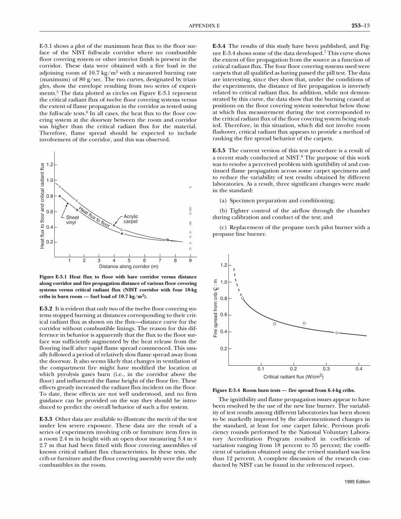
E-3.1 shows a plot of the maximum heat flux to the floor sur-face of the NIST full-scale corridor where no combustiblefloor covering system or other interior finish is present in thecorridor. These data were obtained with a fire load in theadjoining room of 10.7 kg/m2 with a measured burning rate(maximum) of 80 g/sec. The two curves, designated by trian-gles, show the envelope resulting from two series of experi-ments.5 The data plotted as circles on Figure E-3.1 representthe critical radiant flux of twelve floor covering systems versusthe extent of flame propagation in the corridor as tested usingthe full-scale tests.6 In all cases, the heat flux to the floor cov-ering system at the doorway between the room and corridorwas higher than the critical radiant flux for the material.Therefore, flame spread should be expected to includeinvolvement of the corridor, and this was observed.
Figure E-3.1 Heat flux to floor with bare corridor versus distancealong corridor and fire propagation distance of various floor coveringsystems versus critical radiant flux (NIST corridor with four 18-kgcribs in burn room — fuel load of 10.7 kg/m2).
E-3.2 It is evident that only two of the twelve floor covering sys-tems stopped burning at distances corresponding to their crit-ical radiant flux as shown on the flux—distance curve for thecorridor without combustible linings. The reason for this dif-ference in behavior is apparently that the flux to the floor sur-face was sufficiently augmented by the heat release from theflooring itself after rapid flame spread commenced. This usu-ally followed a period of relatively slow flame spread away fromthe doorway. It also seems likely that changes in ventilation ofthe compartment fire might have modified the location atwhich pyrolysis gases burn (i.e., in the corridor above thefloor) and influenced the flame height of the floor fire. Theseeffects greatly increased the radiant flux incident on the floor.To date, these effects are not well understood, and no firmguidance can be provided on the way they should be intro-duced to predict the overall behavior of such a fire system.
E-3.3 Other data are available to illustrate the merit of the testunder less severe exposure. These data are the result of aseries of experiments involving crib or furniture item fires ina room 2.4 m in height with an open door measuring 3.4 m ×2.7 m that had been fitted with floor covering assemblies ofknown critical radiant flux characteristics. In these tests, thecrib or furniture and the floor covering assembly were the onlycombustibles in the room.
E-3.4 The results of this study have been published, and Fig-ure E-3.4 shows some of the data developed.7 This curve showsthe extent of fire propagation from the source as a function ofcritical radiant flux. The four floor covering systems used werecarpets that all qualified as having passed the pill test. The dataare interesting, since they show that, under the conditions ofthe experiments, the distance of fire propagation is inverselyrelated to critical radiant flux. In addition, while not demon-strated by this curve, the data show that the burning ceased atpositions on the floor covering system somewhat below thoseat which flux measurement during the test corresponded tothe critical radiant flux of the floor covering system being stud-ied. Therefore, in this situation, which did not involve roomflashover, critical radiant flux appears to provide a method ofranking the fire spread behavior of the carpets.
E-3.5 The current version of this test procedure is a result ofa recent study conducted at NIST.8 The purpose of this workwas to resolve a perceived problem with ignitibility of and con-tinued flame propagation across some carpet specimens andto reduce the variability of test results obtained by differentlaboratories. As a result, three significant changes were madein the standard:
(a) Specimen preparation and conditioning;
(b) Tighter control of the airflow through the chamberduring calibration and conduct of the test; and
(c) Replacement of the propane torch pilot burner with apropane line burner.
Figure E-3.4 Room burn tests — fire spread from 6.4-kg cribs.
The ignitibility and flame propagation issues appear to havebeen resolved by the use of the new line burner. The variabil-ity of test results among different laboratories has been shownto be markedly improved by the aforementioned changes inthe standard, at least for one carpet fabric. Previous profi-ciency rounds performed by the National Voluntary Labora-tory Accreditation Program resulted in coefficients ofvariation ranging from 18 percent to 35 percent; the coeffi-cient of variation obtained using the revised standard was lessthan 12 percent. A complete discussion of the research con-ducted by NIST can be found in the referenced report.
Acryliccarpet
Sheetvinyl
1 2 3 4 5 6 7 8 9Distance along corridor (m)
0.2
0.4
0.6
0.8
1.0
1.2
Hea
t flu
x to
floo
r an
d cr
itica
l rad
iant
flux
Heat flux to floor
0.40.30.20.1
Critical radiant flux (W/cm2)
0.2
0.4
0.6
0.8
1.0
1.2
Fire
spr
ead
from
crib
C :
mL
1995 Edition
253–14 CRITICAL RADIANT FLUX OF FLOOR COVERING SYSTEMS USING A RADIANT HEAT ENERGY SOURCE
E-4 Summary.
E-4.1 It should be recognized that the critical radiant flux testmethod provides a useful way of ranking floor covering sys-tems on the basis of this important fire property. However, thisis only one of several parameters that determine the firebehavior of floor covering systems. Critical radiant flux indi-cates the threshold above which flame spread occurs. To usethis property in fire safety estimates, the probable heat fluxexposure to the floor from the initiating fire needs to bejudged. Such estimates must, for the present, depend on judg-ment or data from prototype experiments. Once a fire is initi-ated in a corridor, other parameters such as critical radiantflux for ignition and rate of flame spread, as well as corridorconfiguration and the presence of combustibles such as ceil-ing and wall linings, can be important in determining the ulti-mate spread of fire.
E-4.2 Therefore, establishment of criteria for critical radiantflux of floor covering systems can be expected to reduce, butnot to eliminate, the incidents of extensive flame spread offloor covering systems.
E-4.3 In this procedure, the specimens are subjected to one ormore specific sets of laboratory fire test exposure conditions.If different test conditions are substituted or the anticipatedend-use conditions are changed, it might not be possible topredict changes in the performance characteristics measuredby using this test. Therefore, the results are valid only for thefire test exposure conditions described in this procedure.
E-4.4 If the test results obtained by this standard are to be con-sidered in the total assessment of fire risk, then all pertinentestablished criteria for fire risk assessment are to be includedin the consideration.
E-5 Research and Development.
E-5.1 For research and development purposes, it might bedesirable to measure the rate of flame spread advance.
E-5.2 A metal scale marked at 10-mm intervals can be installedon the back of the platform or on the back wall of the cham-ber.
E-5.3 For fire hazard assessment purposes, it might be desir-able to measure the extent of flame travel after a prescribedburning period (e.g., 15 minutes). The use of the metal scaledescribed in E-5.2 is adequate for this purpose.
1Fung, F. C. W., Suchomel, M. R., and Oglesby, P. L., “TheNBS Program on Corridor Fires,” Fire Journal, Vol. 61, No. 3,1973, pp. 41-48.
2Quintere, James and Huggett, Clayton, “An Evaluation ofFlame Spread Test Methods for Floor Covering Materials,”National Bureau of Standards Special Publication 411, U.S.
Government Printing Office, Washington, DC, November1974, pp. 59-89.
3Benjamin, I. and Adams, H., “The Flooring Radiant PanelTest and Proposed Criteria,” Fire Journal, Vol. 70, No. 2, March1976.
4Quintere, James, “The Application and Interpretation of aTest Method to Determine the Hazard of Floor Covering FireSpread in Building Corridors,” International Symposium onFire Safety of Combustible Materials, University of Edinburgh,October 1975.
5Quintiere, James, private communication.6Hartzel, L. G., “Development of a Radiant Panel Test for
Flooring Materials,” National Bureau of Standards, NBSIR 74-495, May 1974.
7Tu, King-Mon and Davis, Sanford, “Flame Spread of CarpetSystems Involved in Room Fires,” National Bureau of Stan-dards, NBSIR 76-1013, June 1976.
8Davis, Sanford, Lawson, J. Randall, and Parker, William J.,“Examination of the Variability of the ASTM E648 Standardwith Respect to Carpets,” National Institute of Standards andTechnology, NISTIR 89-4191, October 1989.
Appendix F Precision and Bias
This Appendix is not a part of the requirements of this NFPA docu-ment but is included for informational purposes only.
F-1 Introduction. This statement is based on the results oftwo factorially designed experiments performed by thirteenlaboratories in which a total of eighteen floor covering systemswere tested.
F-2 Test Results. Defining a test result as the average of threereplicate determinations, the repeatability (within laboratoryvariability) was about 20 percent of the measured value andthe reproducibility (among laboratory variability) was about35 percent of the measured value. Based upon changes thathave been made in this standard, a new precision and biasstatement is being prepared.
NOTE 1: “Repeatability” is a quantity that is exceeded onlyabout 5 percent of the time by the difference, taken in absolutevalue, of two randomly selected results obtained by the samelaboratory on a given material.1
NOTE 2: “Reproducibility” is a quantity that is exceeded onlyabout 5 percent of the time by the difference, taken in absolutevalue, of two single test results made on the same material bytwo, randomly selected laboratories.1
1Mandel, John, “Repeatability and Reproducibility,” Materi-als Research and Standards, MTRSA, Vol. 11, No. 8, p. 8.