26th INTERNATIONAL CONGRESS OF THE AERONAUTICAL SCIENCES PERFORMANCE ANALYSIS OF A 3D SCRAMJET INTAKE Birgit U. Reinartz CATS, RWTH Aachen University, Germany Keywords: scramjet, hypersonic, intake, CFD Abstract A combined experimental as well as computa- tional analysis of a complete scramjet demonstra- tor model has been initiated. The experimental tests will take place under real flight conditions at a hypersonic wind tunnel. Prior to those tests, a numerical analysis of the performance of the demonstrator geometry is conducted. In the cur- rent paper, the results of the performance analysis for the newly designed three-dimensional intake employing a single outer compression ramp as well as side wall compression are discussed. It is shown that the intake is able to generate flow con- ditions required for stable supersonic combustion using a central strut injector. 1 Introduction Within the frame of the Research Training Group (GRK) ”Aerothermodynamic Design of a Scram- jet Engine for Future Space Transportation Sys- tems”, a combined numerical as well as experi- mental analysis of a complete scramjet demon- strator model has been initiated. The experimen- tal tests are being performed under real flight conditions at the hypersonic wind tunnel AT-303 of the Institute of Theoretical and Applied Me- chanics (ITAM) in Novosibirsk, Russia. One of the key interests of the Research Training Group is proving that central strut injectors perform best for large combustors as they are needed for civil applications in space transportation. Two differ- ent central strut injectors which have been devel- oped in Germany over the last decade [7] will be tested during the test campaign in Russia. So far these injectors have only been used in connected pipe facilities where the flow obstruction due to the struts had a large effect on the performance. The pending demonstrator tests are a much ap- preciated opportunity to test those injectors un- der improved conditions because a larger com- bustion chamber will be realized. Before, a vari- ation of a 3D mixed compression inlet tested be- fore at ITAM [6] was analyzed for the pending tests. However, the analyzes showed the height of the intake exit to be too small to obtain good strut injector conditions [13]. Thus, a new 3D intake was designed (see Fig. 1) using a single compres- sion ramp with a deflection of 14 degrees and a sweep angle of 45. The sidewall compression an- gle varies between 7.7 and 10.2 degrees. The in- take uses a straight lip. The throat has a height of 34.3 mm and is located 644 mm downstream of the ramp leading edge. Subsequent to the throat, the intake opens by 2 degrees to compensate for the growing boundary layer. At x=166 mm, there is a step on the upper and lower intake wall of 1 mm each. Here, the diamond shaped injectors will be mounted (also shown in Fig. 1). However, for the current performance analysis of the intake at a flight Mach number of 8 the geometry of the injectors was not considered. The performance of the inlet can be assessed in form of aerodynamic parameters. Typical performance parameters are the mass flow ra- tio MFR, the total pressure recovery factor π C and the kinetic energy efficiency η KE . The mass flow ratio specifies how much of the maximum possible amount of flow at freestream conditions through the inlet is being captured. When isen- tropic expansion is assumed, the kinetic energy efficiency is the ratio of kinetic energy of the de- 1
Transcript
26th INTERNATIONAL CONGRESS OF THE AERONAUTICAL SCIENCES
PERFORMANCE ANALYSIS OF A 3D SCRAMJET INTAKE
Birgit U. ReinartzCATS, RWTH Aachen University, Germany
Keywords: scramjet, hypersonic, intake, CFD
Abstract
A combined experimental as well as computa-tional analysis of a complete scramjet demonstra-tor model has been initiated. The experimentaltests will take place under real flight conditionsat a hypersonic wind tunnel. Prior to those tests,a numerical analysis of the performance of thedemonstrator geometry is conducted. In the cur-rent paper, the results of the performance analysisfor the newly designed three-dimensional intakeemploying a single outer compression ramp aswell as side wall compression are discussed. It isshown that the intake is able to generate flow con-ditions required for stable supersonic combustionusing a central strut injector.
1 Introduction
Within the frame of the Research Training Group(GRK) ”Aerothermodynamic Design of a Scram-jet Engine for Future Space Transportation Sys-tems”, a combined numerical as well as experi-mental analysis of a complete scramjet demon-strator model has been initiated. The experimen-tal tests are being performed under real flightconditions at the hypersonic wind tunnel AT-303of the Institute of Theoretical and Applied Me-chanics (ITAM) in Novosibirsk, Russia. One ofthe key interests of the Research Training Groupis proving that central strut injectors perform bestfor large combustors as they are needed for civilapplications in space transportation. Two differ-ent central strut injectors which have been devel-oped in Germany over the last decade [7] will betested during the test campaign in Russia. So farthese injectors have only been used in connected
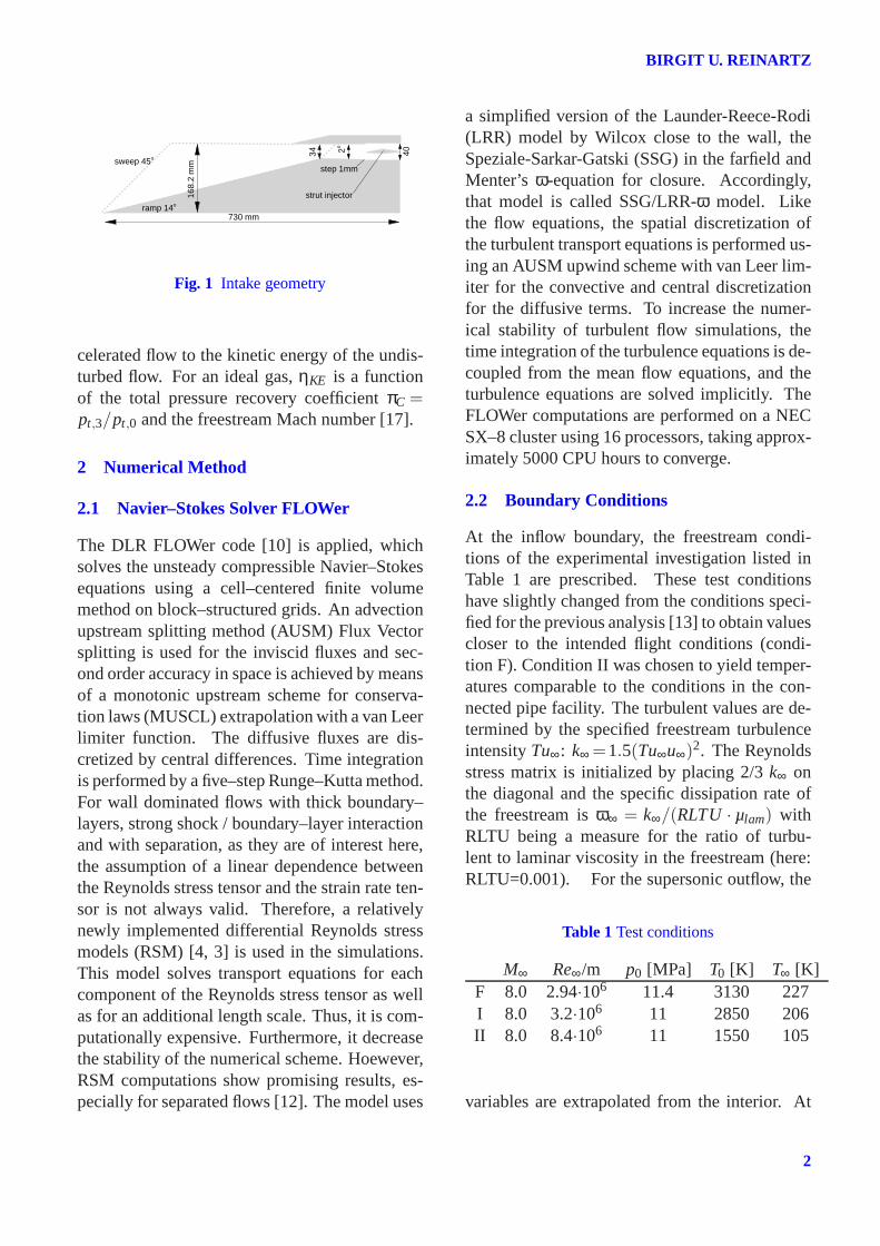
pipe facilities where the flow obstruction due tothe struts had a large effect on the performance.The pending demonstrator tests are a much ap-preciated opportunity to test those injectors un-der improved conditions because a larger com-bustion chamber will be realized. Before, a vari-ation of a 3D mixed compression inlet tested be-fore at ITAM [6] was analyzed for the pendingtests. However, the analyzes showed the height ofthe intake exit to be too small to obtain good strutinjector conditions [13]. Thus, a new 3D intakewas designed (see Fig. 1) using a single compres-sion ramp with a deflection of 14 degrees and asweep angle of 45. The sidewall compression an-gle varies between 7.7 and 10.2 degrees. The in-take uses a straight lip. The throat has a height of34.3 mm and is located 644 mm downstream ofthe ramp leading edge. Subsequent to the throat,the intake opens by 2 degrees to compensate forthe growing boundary layer. At x=166 mm, thereis a step on the upper and lower intake wall of1 mm each. Here, the diamond shaped injectorswill be mounted (also shown in Fig. 1). However,for the current performance analysis of the intakeat a flight Mach number of 8 the geometry of theinjectors was not considered.
The performance of the inlet can be assessedin form of aerodynamic parameters. Typicalperformance parameters are the mass flow ra-tio MFR, the total pressure recovery factorπC
and the kinetic energy efficiencyηKE. The massflow ratio specifies how much of the maximumpossible amount of flow at freestream conditionsthrough the inlet is being captured. When isen-tropic expansion is assumed, the kinetic energyefficiency is the ratio of kinetic energy of the de-
1
BIRGIT U. REINARTZ
sweep 45o
ramp 14o
730 mm
34 2o
40
step 1mm
168.
2m
mstrut injector
Fig. 1 Intake geometry
celerated flow to the kinetic energy of the undis-turbed flow. For an ideal gas,ηKE is a functionof the total pressure recovery coefficientπC =pt,3/pt,0 and the freestream Mach number [17].
2 Numerical Method
2.1 Navier–Stokes Solver FLOWer
The DLR FLOWer code [10] is applied, whichsolves the unsteady compressible Navier–Stokesequations using a cell–centered finite volumemethod on block–structured grids. An advectionupstream splitting method (AUSM) Flux Vectorsplitting is used for the inviscid fluxes and sec-ond order accuracy in space is achieved by meansof a monotonic upstream scheme for conserva-tion laws (MUSCL) extrapolation with a van Leerlimiter function. The diffusive fluxes are dis-cretized by central differences. Time integrationis performed by a five–step Runge–Kutta method.For wall dominated flows with thick boundary–layers, strong shock / boundary–layer interactionand with separation, as they are of interest here,the assumption of a linear dependence betweenthe Reynolds stress tensor and the strain rate ten-sor is not always valid. Therefore, a relativelynewly implemented differential Reynolds stressmodels (RSM) [4, 3] is used in the simulations.This model solves transport equations for eachcomponent of the Reynolds stress tensor as wellas for an additional length scale. Thus, it is com-putationally expensive. Furthermore, it decreasethe stability of the numerical scheme. Hoewever,RSM computations show promising results, es-pecially for separated flows [12]. The model uses
a simplified version of the Launder-Reece-Rodi(LRR) model by Wilcox close to the wall, theSpeziale-Sarkar-Gatski (SSG) in the farfield andMenter’s ω-equation for closure. Accordingly,that model is called SSG/LRR-ω model. Likethe flow equations, the spatial discretization ofthe turbulent transport equations is performed us-ing an AUSM upwind scheme with van Leer lim-iter for the convective and central discretizationfor the diffusive terms. To increase the numer-ical stability of turbulent flow simulations, thetime integration of the turbulence equations is de-coupled from the mean flow equations, and theturbulence equations are solved implicitly. TheFLOWer computations are performed on a NECSX–8 cluster using 16 processors, taking approx-imately 5000 CPU hours to converge.
2.2 Boundary Conditions
At the inflow boundary, the freestream condi-tions of the experimental investigation listed inTable 1 are prescribed. These test conditionshave slightly changed from the conditions speci-fied for the previous analysis [13] to obtain valuescloser to the intended flight conditions (condi-tion F). Condition II was chosen to yield temper-atures comparable to the conditions in the con-nected pipe facility. The turbulent values are de-termined by the specified freestream turbulenceintensityTu∞: k∞ =1.5(Tu∞u∞)2. The Reynoldsstress matrix is initialized by placing 2/3k∞ onthe diagonal and the specific dissipation rate ofthe freestream isω∞ = k∞/(RLTU · µlam) withRLTU being a measure for the ratio of turbu-lent to laminar viscosity in the freestream (here:RLTU=0.001). For the supersonic outflow, the
solid walls, the no-slip condition is enforced bysetting the velocity components and the normalpressure gradient to zero. Due to the short mea-surement times in a high-enthalpy facility it is as-sumed the model remains at a constant ambienttemperature ofTwall = 293K. Additionally, theReynolds stresses are set to zero at the wall andthe respective length scale is prescribed based onthe first grid spacing accordining to Menter.
2.3 Numerical Accuracy
A complete validation of the FLOWer code hasbeen performed by the DLR prior to its release[1, 11] and continued validation is achieved bythe analyses documented in subsequent publica-tions [15, 16, 2]. Furthermore, FLOWer has al-ready been successfully used in the analysis of3D hypersonic intake flows [12, 14, 8, 9].
3 Results
The design of the tested scramjet demonstrator iscentered around the supersonic combustion pro-cess employing a central strut injector with hy-drogen injection [5, 7]. The primary purpose ofthe intake is to provide high-pressure flow to theengine with a minimum of aerodynamic lossesand a static temperature high enough to allowfor stable combustion. Additionally, the combus-tion process itself causes a variation of the in-let back pressure which needs to be consideredwhen analyzing the performance of the wholesystem. However, earlier analyses of the com-bustion chamber have shown the back pressure tobe negligible due to the lean mixture of fuel andair currently used. Another critical factor is thestatic temperature at the end of the compressionprocess which has to be high enough to ensureself ignition of the hydrogen. Thus, the currentanalysis focused mainly on the combustor inflowas well as yields some clues concerning place-ment of pressure transducers in the intake model.
For the numerical analysis of the half modelapproximately 3.5 Mio grid cells are used, 433nodes in the main flow direction and 81 x 114 and81 x 145 for the cross section before and after the
step, respectively. The decomposition of the gridis 16 blocks needed for the MPI parallelization.The grid spacing stretches away from the wallsand is clustered at the leading egdes of ramp andcowl. Otherwise, great care is taken to obtaina overall homogenous grid spacing (see Fig. 2).Earlier analysis showed a certain grid sensitivityof hypersonic shock wave boundary layer inter-action when local grid refinement is applied [14].A minimum wall spacing of∆ = 1.e-06 is used inall directions yielding ay+ of 1.
z [m]0 0.01 0.02 0.03
0.13
0.14
0.15
0.16
side
wal
l
sym
met
rypl
ane
y [m]
exit plane: 81 x 145 nodes
Fig. 2 Grid cell distribution at exit plane.
External compression of the inlet is ensuredby a ramp angle of 14o and two side wedges withdeflection angles of 7.7−10.2o and a sweep an-gle of 45o each. The overall dimensions of theintake can be see in Fig. 1. In Fig. 3, the Machnumber isolines of the center plane show the gapbetween ramp shock and engine cowl to be toolarge, resulting in an unneccessarily high spillagedrag. Approximately, one third of the capturedmass flow is lost here. The reason for the gap isthe displacement of the ramp shock (which wasdesigned using the shock-to-lip condition) by theside wall compression. At first, it was assumedthat the lip shock impinging on the thick hyper-sonic ramp boundary layer might have a strongupstream effect. This was supported by the dis-tribution of wall pressure shown in Fig. 4. How-ever, by using a bleed boundary condition at theimpingement point of the lip shock (∆xbleed = 20
3
BIRGIT U. REINARTZ
mm between 0.562 and 0.582 mm downstream ofthe leading edge) the separation was strongly re-duced (see Fig. 5) without reducing spillage drag.Currently, simulations are performed where theramp is 30 mm shorter (everything else is keptconstant) to bring the ramp shock closer to theengine cowl. The distribution at
x [m]0 0.1 0.2 0.3 0.4 0.5 0.6 0.7
0
0.1
0.2
0.3
0 2 4 6 8
3D inletM∞=8, Re∞= 3.21 Mio/m, T∞= 120 KMach number (center plane)
M
Fig. 3 Mach isolines at center plane for 3D intake.
x [m]0 0.1 0.2 0.3 0.4 0.5 0.6 0.7
0
1
2
3
4
5
cowl, T0= 2850 Kramp, T0= 2850 K
cp
3D Intake, M∞= 8,surface pressure center plane
x [m]0 0.1 0.2 0.3 0.4 0.5 0.6 0.7
0
1
2
3
4
5
cowl, T0= 1550 Kramp, T0= 1550 Kcp
Fig. 4 Surface pressure distribution along center.
x [m]0 0.1 0.2 0.3 0.4 0.5 0.6 0.7
0
0.1
0.2
0.3
0 2 4 6 8
3D inletM∞=8, Re∞= 3.21 Mio/m, T∞= 120 KMach number (center plane)
M
Fig. 5 Mach number contours at center planewith bleed.
z [m]0 0.01 0.02 0.03
0.13
0.14
0.15
0.16
3
2
1
0
side
wal
l
sym
met
rypl
ane
y [m] M
3D inlet, M=8, T0=1550KMach number (exit plane)
z [m]0 0.01 0.02 0.03
0.13
0.14
0.15
0.16
1550
1340
1130
920
710
500
side
wal
l
sym
met
rypl
ane
y [m] T [K]
3D inlet, M=8, T0=1550KTemperature (exit plane)
Fig. 6 Mach number and temperature isolines onexit plane of 3D intake (condition II).
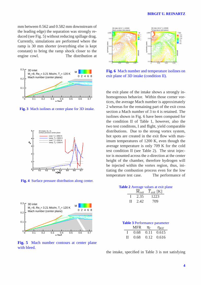
the exit plane of the intake shows a strongly in-homogenous behavior. Within those corner vor-tices, the average Mach number is approximately2 whereas for the remaining part of the exit crosssection a Mach number of 3 to 4 is retained. Theisolines shown in Fig. 6 have been computed forthe condition II of Table 1, however, also thetwo test conditons, I and flight, yield comparabledistributions. Due to the strong vortex system,hot spots are created in the exit flow with max-imum temperatures of 1200 K, even though theaverage temperature is only 709 K for the coldtest condition II (see Table 2). The strut injec-tor is mounted across the z-direction at the centerheight of the chamber, therefore hydrogen willbe injected within the vortex region, thus, ini-tiating the combustion process even for the lowtemperature test case. The performance of
Table 2Average values at exit planeMexit Texit [K]
I 2.35 1223II 2.42 709
Table 3Performance parameterMFR πC ηKE
I 0.68 0.11 0.615II 0.68 0.12 0.616
the intake, specified in Table 3 is not satisfying
4
PERFORMANCE ANALYSIS OF A 3D SCRAMJET INTAKE
from the intlet designer point of view. However,the exit condition should suffice to achieve a sta-ble supersonic combustion which is the main goalof the pending test campaign. Nevertheless, thecomputational intake analysis is continued to ob-tain an improved inlet design without changingtoo many design parameters and jeopardizing thethe combustion process.
4 Conclusions
In this paper the performance analysis of the in-take at a flight Mach number of 8 is performed.The role of the present numerical computationsis to complement the experimental investigationsand to enhance the understanding of the obtainedresults. Additionally, the numerical simulationcompletes the knowledge of the flow field in ar-eas which are not accessible to measurements andallows for an overall performance analysis of theinlet geometry. The current analysis denotes thedeveloping corner vortices as a key feature to en-sure self ignition for the low temperature (T0 =1550 K) experimental test run.
Acknowledgments
This work has been financially supported by theDeutsche Forschungsgemeinschaft (DFG) withinthe frame of the German Research TrainingGroup GRK 1095/1.
4.1 Copyright Statement
The authors confirm that they, and/or their company orinstitution, hold copyright on all of the original mate-rial included in their paper. They also confirm theyhave obtained permission, from the copyright holderof any third party material included in their paper, topublish it as part of their paper. The authors grant fullpermission for the publication and distribution of theirpaper as part of the ICAS2008 proceedings or as indi-vidual off-prints from the proceedings.
References
[1] Becker N, Kroll N, Rossow C. C, and ThieleF. Numerical flow calculations for complete
aircraft - the megaflow project.Proc DGLRJahrbuch 1998, Vol. 1, pp 355–364, Bonn, Ger-many, 1998. Deutsche Gesellschaft für Luft-und Raumfahrt (DGLR).
[2] Coratekin T. A, van Keuk J, and Ballmann J. Onthe performance of upwind schemes and turbu-lence models in hypersonic flows.AIAA Jour-nal, Vol. 42, No 5, pp 945–957, May 2004.
[3] Eisfeld B. Implementation of reynolds stressmodels into the dlr-flower code. IB 124-2004/31, DLR, Institute of Aerodynamics andFlow Technology, 2004.
[4] Eisfeld B and Brodersen O. Advanced turbu-lence modelling and stress analysis for the dlr-f6configuration. AIAA Paper 2005-4727, 2005.
[5] Gerlinger P, Kasal P, Stoll P, and d. Brügge-mann. Experimental and theoretical investiga-tion on 2d and 3d parallel hydrogen/air mixingin a supersonic flow. International Society forAir Breathing Engines, Paper ISABE-01-0189,2001.
[6] Goonko Y. P, Kharitonov A. M, Mazhul I. I,Zvegintsev V. I, Nalivaichenko D. G, andChirkashenko V. F. Investigations of a scram-jet model at hypersonic velocities and highreynolds numbers. AIAA Paper 2002-5273,2002.
[7] Kasal P, Gerlinger P, Walther R, von Wolfers-dorf J, and Weigand B. Supersonic combus-tion: Fundamental investigation of aerothermo-dynamic key problems. AIAA Paper 2002-5119, 2002.
[8] Krause M and Ballmann J. Numerical simula-tions and design of a scramjet intake using twodifferent rans solver. AIAA Paper 2007–5423,2007.
[9] Krause M, Reinartz B, and Ballmann J. Numer-ical computations for designing a scramjet in-take.Proc 25th Congress of International Coun-cil of the Aeronautical Sciences (ICAS), Ham-burg, Germany, 3-8 September 2006, 2006.
[10] Kroll N, Rossow C.-C, Becker K, and Thiele F.The megaflow project.Aerospace Science andTechnology, Vol. 4, No 4, pp 223–237, 2000.
[11] Radespiel R, Rossow C, and Swanson R. Effi-cient cell-vertex multigrid scheme for the three-dimensional navier-stokes equations.AIAAJournal, Vol. 28, No 8, pp 1464–1472, 1990.
5
BIRGIT U. REINARTZ
[12] Reinartz B and Ballmann J. Computation of hy-personic double wedge shock / boundary layerinteraction.Proc 26th International Symposiumon Shock Waves (ISSW 26), Göttingen, Ger-many 16-20 July 2007, 2007.
[13] Reinartz B, Ballmann J, and Behr M. Compu-tational analysis of a 3d hypersonic intake forexperimental testing at mach 8. Aiaa paper.
[14] Reinartz B, Ballmann J, Brown L, Fischer C,and Boyce R. Shock wave / boundary layer in-teraction in hypersonic intake flows.Proc 2ndEuropean Conference on Aero-Space Sciences(EUCASS), Brussels, Belgium 1-6 July 2007,2007.
[15] Reinartz B. U, Ballmann J, Herrmann C, andKoschel W. Aerodynamic performance analysisof a hypersonic inlet isolator using computationand experiment. AIAA Journal of Propulsionand Power, Vol. 19, No 5, pp 868–875, 2003.
[16] van Keuk J, Ballmann J, Sanderson S. R, andHornung H. G. Numerical simulation of exper-iments on shock wave interactions in hyperve-locity flows with chemical reactions. AIAA Pa-per 03–0960, January 2003.
[17] Van Wie D. M. Scramjet inlets. In Curran E. Tand Murthy S. N. B, editors,Scramjet Propul-sion, Vol. 189, pp 447–511, Reston, VA, 2000.AIAA.