HEADQUARTERS, DEPARTMENT OF THE ARMYWASHINGTON, D.C.
28 SEPTEMBER 1983
TECHNICALPRINCIPLES
OF OPERATIONPAGE 1-3
SERVICEUPON RECEIPT
Page 2-1
INSTALLATIONINSTRUCTION
Page 2-5TROUBLE-SHOOTINGPage 2-18
MAINTENANCEPROCEDURES
Page 2-29
MAINTENANCEALLOCATIONCHART (MAC)
Appendix B
TM 11-5815-238-20
WARNING
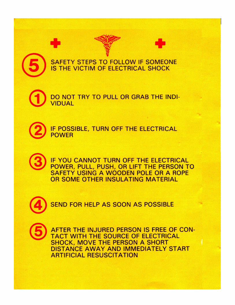
HIGH VOLTAGE is used in operation of this equipment. DEATH ON CONTACT may result if youfail to follow safety requirements in this manual as well as in TB SIG 291.
DON'T TAKE CHANCES!
Turn all equipment to OFF before making any corrections or replacing any parts inside theequipment.
This equipment contains selenium rectifiers which instantly send out poisonous fumes when theyburn out. The smell is like rotten eggs. If you should smell this, get fresh air quickly; providethorough ventilation at all times.
Fumes of TRICHLOROTRIFLUOROETHANE are poisonous; provide thorough ventilation wheneverit is used. Do not use it near open flames or a hot surface. Do not get it on your skin.
A/(B blank)
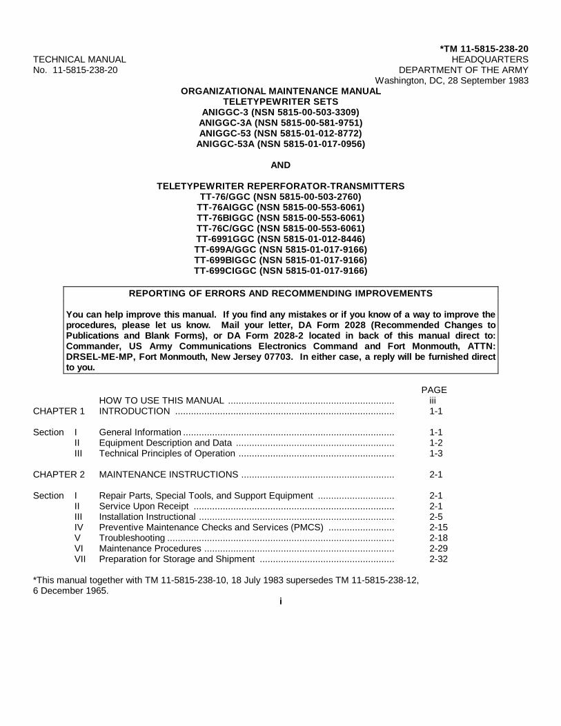
*TM 11-5815-238-20TECHNICAL MANUAL HEADQUARTERSNo. 11-5815-238-20 DEPARTMENT OF THE ARMY
Washington, DC, 28 September 1983ORGANIZATIONAL MAINTENANCE MANUAL
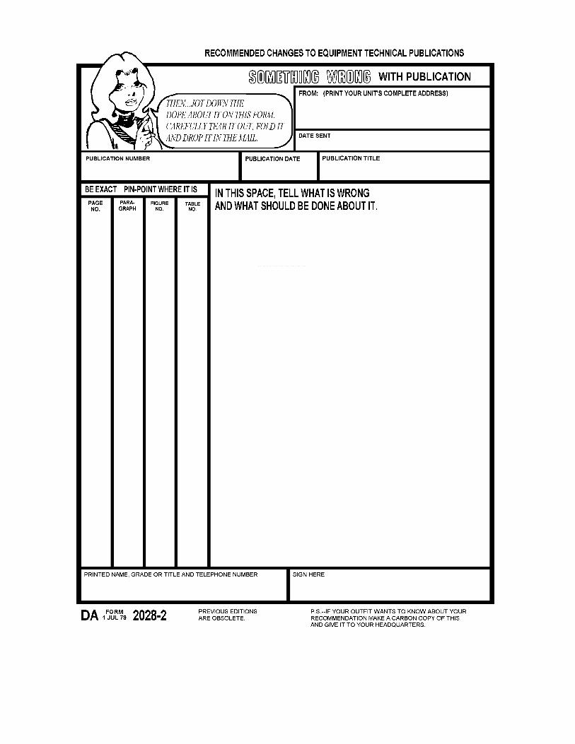
You can help improve this manual. If you find any mistakes or if you know of a way to improve theprocedures, please let us know. Mail your letter, DA Form 2028 (Recommended Changes toPublications and Blank Forms), or DA Form 2028-2 located in back of this manual direct to:Commander, US Army Communications Electronics Command and Fort Monmouth, ATTN:DRSEL-ME-MP, Fort Monmouth, New Jersey 07703. In either case, a reply will be furnished directto you.
PAGEHOW TO USE THIS MANUAL ............................................................... iii
Section I General Information ................................................................................ 1-1II Equipment Description and Data ............................................................ 1-2III Technical Principles of Operation ........................................................... 1-3
Section I Repair Parts, Special Tools, and Support Equipment ............................. 2-1II Service Upon Receipt ............................................................................ 2-1III Installation Instructional .......................................................................... 2-5IV Preventive Maintenance Checks and Services (PMCS) ......................... 2-15V Troubleshooting ...................................................................................... 2-18VI Maintenance Procedures ........................................................................ 2-29VII Preparation for Storage and Shipment ................................................... 2-32
*This manual together with TM 11-5815-238-10, 18 July 1983 supersedes TM 11-5815-238-12,6 December 1965.
i
TM 11-5815-238-20
PAGEAPPENDIX A REFERENCES ................................................................................... A-1
B MAINTENANCE ALLOCATION CHART (MAC) .................................. B-3C EXPENDABLE SUPPLIES AND MATERIALS LIST ............................ C-1
GLOSSARY Glossary-1INDEX Index-1
ii
TM 11-5815-238-20
HOW TO USE THIS MANUAL
• THIS MANUAL TELLS ABOUT THE TYPICAL ARRANGEMENTS OF THE TELETYPEWRITER REPERFORATOR-TRANSMITTER TT-76/GGC.
• ALL THE PROCEDURES IN THIS MANUAL MUST BE EXAMINED BEFORE YOU BEGIN ANY TASK. • THROUGHOUT THIS MANUAL COLOR CODED MARGIN TABS WILL GUIDE YOU TO THE SECTION THAT
CONTAINS THE SPECIFIC INFORMATION YOU NEED. • THIS MANUAL IS ORGANIZED INTO CHAPTERS, SECTIONS, PARAGRAPHS AND ILLUSTRATIONS WHICH
ARE NUMBERED TO HELP YOU FIND INFORMATION ABOUT YOUR EQUIPMENT QUICKLY AND EASILY. • COLOR IS USED TO EMPHASIZE KEY POINTS. • UNFAMILIAR WORDS WILL BE EXPLAINED AT THE BEGINNING OF EACH CHAPTER. • THE SUBJECT INDEX IN THE BACK OF THE MANUAL WILL HELP YOU FIND INFORMATION QUICKLY.
iii
TM 11-5815-238-20
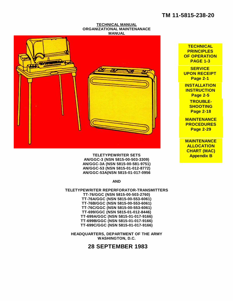
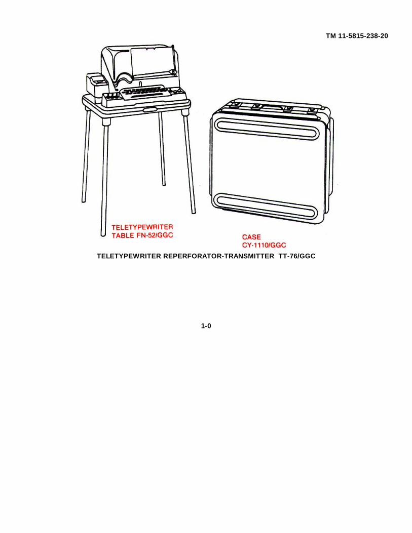
TELETYPEWRITER REPERFORATOR-TRANSMITTER TT-76/GGC
1-0
TM 11-5815-238-20
CHAPTER 1
INTRODUCTION
Section I. GENERAL INFORMATION
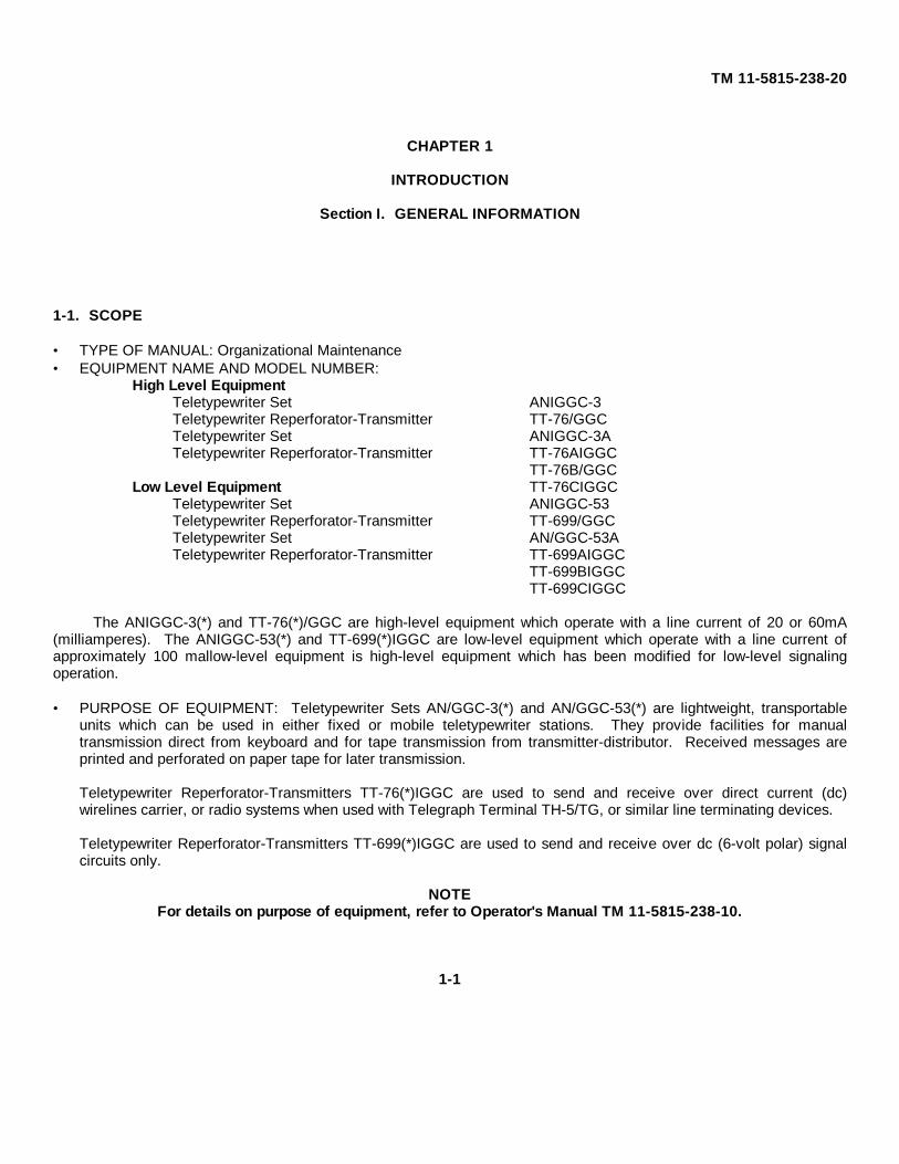
1-1. SCOPE
• TYPE OF MANUAL: Organizational Maintenance• EQUIPMENT NAME AND MODEL NUMBER:
High Level EquipmentTeletypewriter Set ANIGGC-3Teletypewriter Reperforator-Transmitter TT-76/GGCTeletypewriter Set ANIGGC-3ATeletypewriter Reperforator-Transmitter TT-76AIGGC
TT-76B/GGCLow Level Equipment TT-76CIGGC
Teletypewriter Set ANIGGC-53Teletypewriter Reperforator-Transmitter TT-699/GGCTeletypewriter Set AN/GGC-53ATeletypewriter Reperforator-Transmitter TT-699AIGGC
TT-699BIGGCTT-699CIGGC
The ANIGGC-3(*) and TT-76(*)/GGC are high-level equipment which operate with a line current of 20 or 60mA(milliamperes). The ANIGGC-53(*) and TT-699(*)IGGC are low-level equipment which operate with a line current ofapproximately 100 mallow-level equipment is high-level equipment which has been modified for low-level signalingoperation.
• PURPOSE OF EQUIPMENT: Teletypewriter Sets AN/GGC-3(*) and AN/GGC-53(*) are lightweight, transportableunits which can be used in either fixed or mobile teletypewriter stations. They provide facilities for manualtransmission direct from keyboard and for tape transmission from transmitter-distributor. Received messages areprinted and perforated on paper tape for later transmission.
Teletypewriter Reperforator-Transmitters TT-76(*)IGGC are used to send and receive over direct current (dc)wirelines carrier, or radio systems when used with Telegraph Terminal TH-5/TG, or similar line terminating devices.
Teletypewriter Reperforator-Transmitters TT-699(*)IGGC are used to send and receive over dc (6-volt polar) signalcircuits only.
NOTEFor details on purpose of equipment, refer to Operator's Manual TM 11-5815-238-10.
1-1
TM 11-5815-238-20
1-2. MAINTENANCE FORMS, RECORDS AND REPORTS
Department of the Army forms and procedures used for equipment maintenance will be those described by TM 38-750,The Army Maintenance Management System (TAMMS).
1-3. DESTRUCTION OF ARMY MATERIEL TO PREVENT ENEMY USE
Destruction of Army materiel to prevent enemy use is described in TM 750-244-2.
1-4. PREPARATION FOR STORAGE AND SHIPMENT
Description of preparation for storage and shipment are found in Chapter 2, Section VII of this manual.
1-5. NOMENCLATURE CROSS-REFERENCE LIST NOTE
NOTEOfficial nomenclature must be used when filling out report forms or looking up technical manuals.Official nomenclature followed by an (*) designates all models of the equipment referenced in thismanual.
COMMON NAME NOMENCLATURETeletypewriter Teletypewriter Reperforator-Transmitter
TT-76(*)IGGC or Teletypewriter Reperforator-Transmitter TT-699(*)/GGC.
Teletypewriter Set Teletypewriter Set ANIGGC-3(*) or TeletypewriterSet ANIGGC-53(*).
Chad Bin Chad Bin, SM 13-157283.Tuning Fork Fork, Tuning, SC-DL-70237.Inking Ribbon Teletypewriter, Ribbon, DDD-R-311D, type 1,
You can improve this equipment. Tell us if a design is not favorable or if a procedure is difficult to follow. Mail Form SF368 (Quality Deficiency Report) directly to: Commander US Army Communications Electronics Command and FortMonmouth, ATTN: DRSEL-ME-MP, Fort Monmouth, New Jersey 07703. A reply will be sent to you.
Section II. EQUIPMENT DESCRIPTION AND DATA
1-7. EQUIPMENT CHARACTERISTICS, CAPABILITIES AND FEATURES
Refer to Operator's Manual TM 11-5815-238-10.
1-8. LOCATION AND DESCRIPTION OF MAJOR COMPONENTS
Refer to Operator's Manual TM 11-5815-238-10.
1-2
TM 11-5815-238-20
1-9. DIFFERENCES BETWEEN MODELS
Refer to Operator's Manual TM 11-5815-238-10.
1-10. EQUIPMENT DATA
Refer to Operator's Manual TM 11-5815-238-10.
1-11. SAFETY, CARE AND HANDLING
Observe all WARNING, CAUTIONS and NOTES in this manual. This equipment can be extremely dangerous if theseinstructions are not followed.
Section Ill. TECHNICAL PRINCIPLES OF OPERATION
1-12. GENERAL
Major mechanical components for high-level and low-level equipment are the same while their major electricalcomponents are different. The technical principles of operation for plain and lettered models of teletypewriterreperforator-transmitters are the same.
1-13. SIGNALING CODE
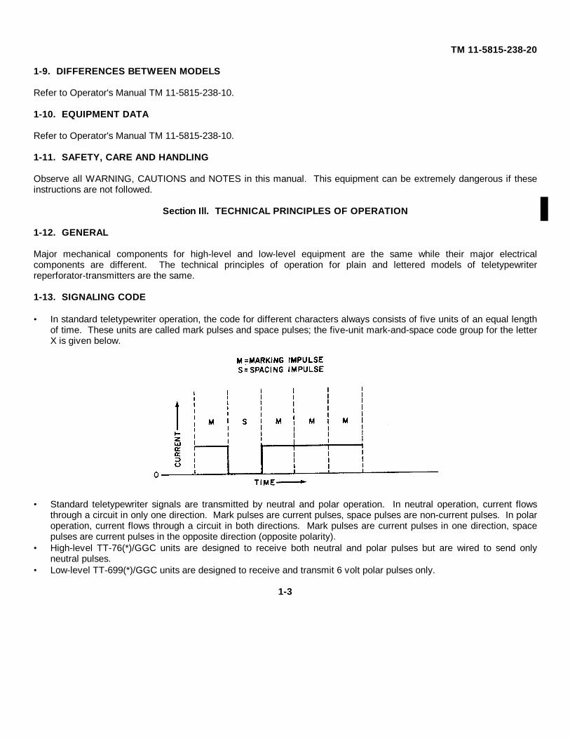
• In standard teletypewriter operation, the code for different characters always consists of five units of an equal lengthof time. These units are called mark pulses and space pulses; the five-unit mark-and-space code group for the letterX is given below.
• Standard teletypewriter signals are transmitted by neutral and polar operation. In neutral operation, current flows
through a circuit in only one direction. Mark pulses are current pulses, space pulses are non-current pulses. In polaroperation, current flows through a circuit in both directions. Mark pulses are current pulses in one direction, spacepulses are current pulses in the opposite direction (opposite polarity).
• High-level TT-76(*)/GGC units are designed to receive both neutral and polar pulses but are wired to send onlyneutral pulses.
• Low-level TT-699(*)/GGC units are designed to receive and transmit 6 volt polar pulses only.
1-3
TM 11-5815-238-20
1-14. BASIC HIGH-LEVEL TELETYPEWRITER SYSTEM
•Pulses sent from either sending contact operates selector magnets in both teletypewriters. Both teletypewriters cansend and receive. Additional teletypewriters, sending units and/or receiving units can be added to this system, if needed.
1-15. BASIC LOW-LEVEL TELETYPEWRITER SYSTEM
•Mark (negative) and space (positive) pulses are made at sending TELETYPEWRITER A by closing and opening thesending contacts. The transmitter module turns these closings and openings into 6 volt polar signals and applies them tothe signal lines. These polar signals are received by TELETYPEWRITER B receiver module and processed through theselector magnet driver to the selector magnet.
•Both teletypewriters are equipped with send and receive components but full two-way communication would require foursignal lines and transmitters and receivers interconnected. Additional receiving units may be connected to a sending uniton a parallel basis only.
Ground and power ................................................................................................................. 2-6Installation .................................................................................................................................... 2-5Maintenance procedures .............................................................................................................. 2-29Preparation for storage and shipment ........................................................................................... 2-32PMCS table .................................................................................................................................. 2-17Service upon receipt .................................................................................................................... 2-1Signal circuit connections.
for TT-76(*)IGGC . ................................................................................................................ 2-9for TT-699(*)/GGC ................................................................................................................. 2-13
Section I. REPAIR PARTS, SPECIAL TOOLS AND SUPPORT EQUIPMENT
2-1. TOOLS AND TEST EQUIPMENTTools and test equipment for Organizational Maintenance of ANIGGC-3(*) and AN/GGC-53(*) are listed in theMaintenance Allocation Chart (MAC) in Appendix B of this manual.2-2. SPECIAL TOOLS, TMDE AND SUPPORT EQUIPMENTThere are no special tools or TMDE required for this equipment.2-3. REPAIR PARTSRepair parts are listed and illustrated in the Repair Parts and Special Tools List TM 11-5815-238-20P coveringOrganizational Maintenance for this equipment.
Section II. SERVICE UPON RECEIPT2-4. UNPACKING EQUIPMENT
Prevent personal injury when removing steel straps by wearing heavy gloves and protectiveeyewear. Do not handle shipping container by the steel straps.
CAUTIONWhen unpacking equipment, do not push tools inside the shipping container, as equipment may bedamaged.
2-1
TM 11-5815-238-20
NOTEUnpacking instructions for Teletypewriter Sets ANIGGC-53(*) are the same as those given belowfor AN/GGC-3(*). Unpacking instructions for Teletypewriter Reperforator-Transmitters TT-699(*)/GGC are the same as those given below for TT-76(*)IGGC.
Teletypewriter Sets ANIGGC-3(*)
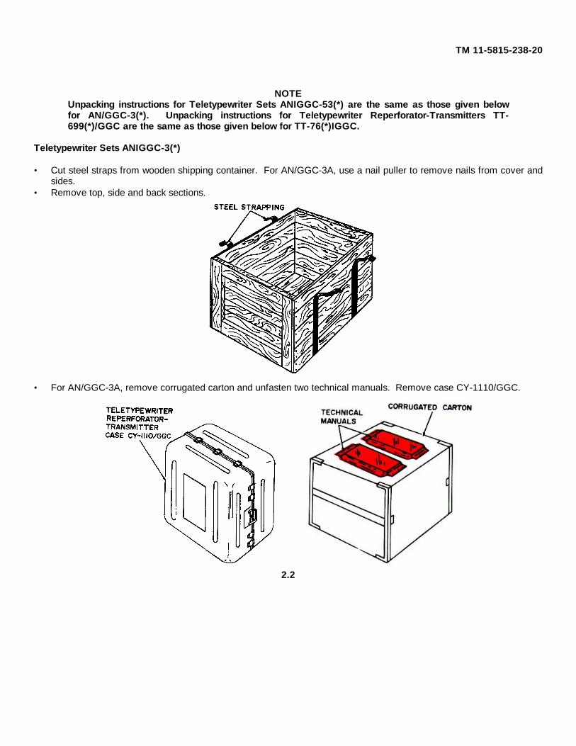
• Cut steel straps from wooden shipping container. For AN/GGC-3A, use a nail puller to remove nails from cover andsides.
• Remove top, side and back sections.
• For AN/GGC-3A, remove corrugated carton and unfasten two technical manuals. Remove case CY-1110/GGC.
2.2
TM 11-5815-238-20
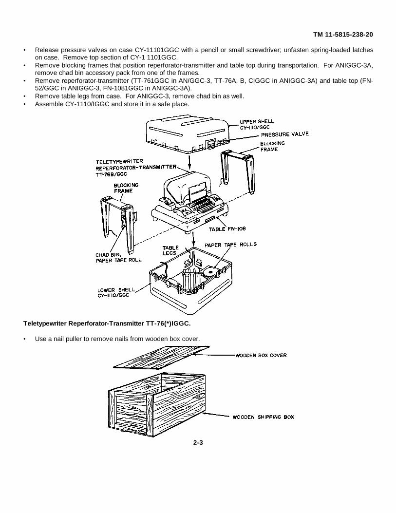
• Release pressure valves on case CY-11101GGC with a pencil or small screwdriver; unfasten spring-loaded latcheson case. Remove top section of CY-1 1101GGC.
• Remove blocking frames that position reperforator-transmitter and table top during transportation. For ANIGGC-3A,remove chad bin accessory pack from one of the frames.
• Remove reperforator-transmitter (TT-761GGC in AN/GGC-3, TT-76A, B, CIGGC in ANIGGC-3A) and table top (FN-52/GGC in ANIGGC-3, FN-1081GGC in ANIGGC-3A).
• Remove table legs from case. For ANIGGC-3, remove chad bin as well.• Assemble CY-1110/IGGC and store it in a safe place.
• Use a nail puller to remove nails from wooden box cover.
2-3
TM 11-5815-238-20
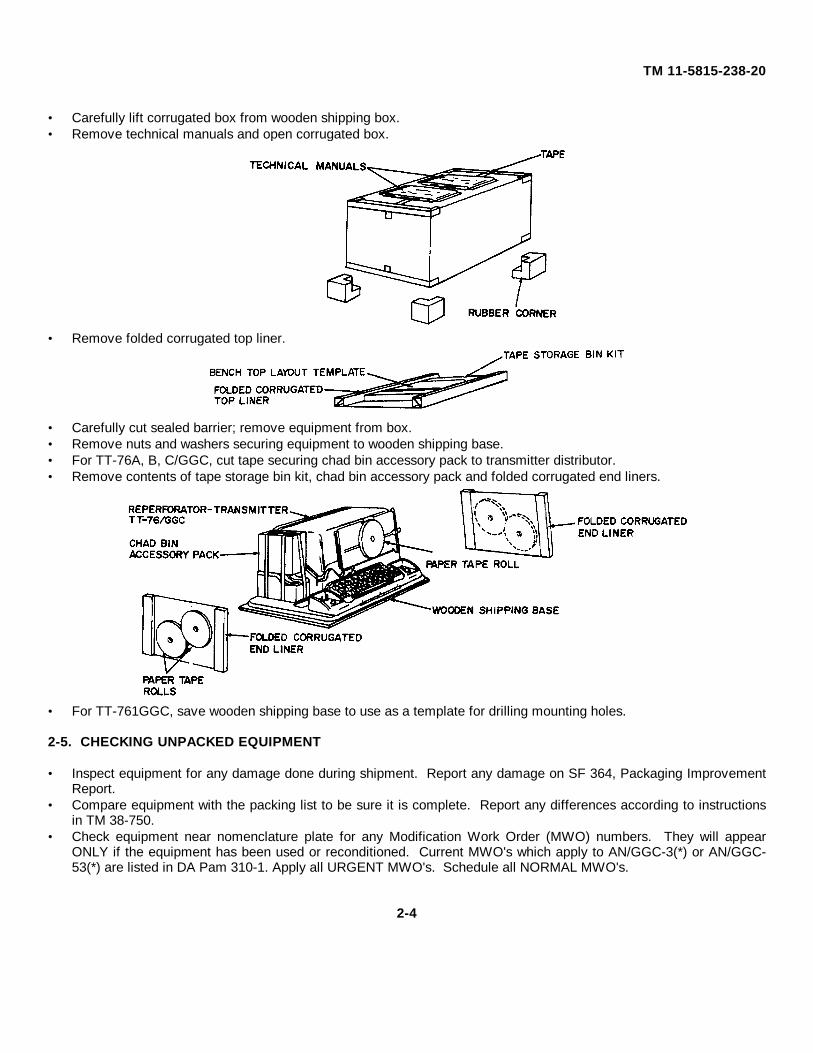
• Carefully lift corrugated box from wooden shipping box.• Remove technical manuals and open corrugated box.
• Remove folded corrugated top liner.
• Carefully cut sealed barrier; remove equipment from box.• Remove nuts and washers securing equipment to wooden shipping base.• For TT-76A, B, C/GGC, cut tape securing chad bin accessory pack to transmitter distributor.• Remove contents of tape storage bin kit, chad bin accessory pack and folded corrugated end liners.
• For TT-761GGC, save wooden shipping base to use as a template for drilling mounting holes.
2-5. CHECKING UNPACKED EQUIPMENT
• Inspect equipment for any damage done during shipment. Report any damage on SF 364, Packaging ImprovementReport.
• Compare equipment with the packing list to be sure it is complete. Report any differences according to instructionsin TM 38-750.
• Check equipment near nomenclature plate for any Modification Work Order (MWO) numbers. They will appearONLY if the equipment has been used or reconditioned. Current MWO's which apply to AN/GGC-3(*) or AN/GGC-53(*) are listed in DA Pam 310-1. Apply all URGENT MWO's. Schedule all NORMAL MWO's.
2-4
TM 11-5815-238-20
Section III. INSTALLATION INSTRUCTIONS
2-6. COMPONENT ASSEMBLY
Teletypewriter Set ANIGGC-3(*)
• Place TT-76/GGC and table FN-52/GGC, on which it is mounted, on a flat surface. Lift front of FN-52/GGC until it isalmost upright.
• Screw four table legs into leg. mounts on underside of table top.• Press chad bin into holder under table and secure it with the wire retainer.• To install paper tape and inking ribbon, refer to Operator's Manual TM 11-5815-238-10.
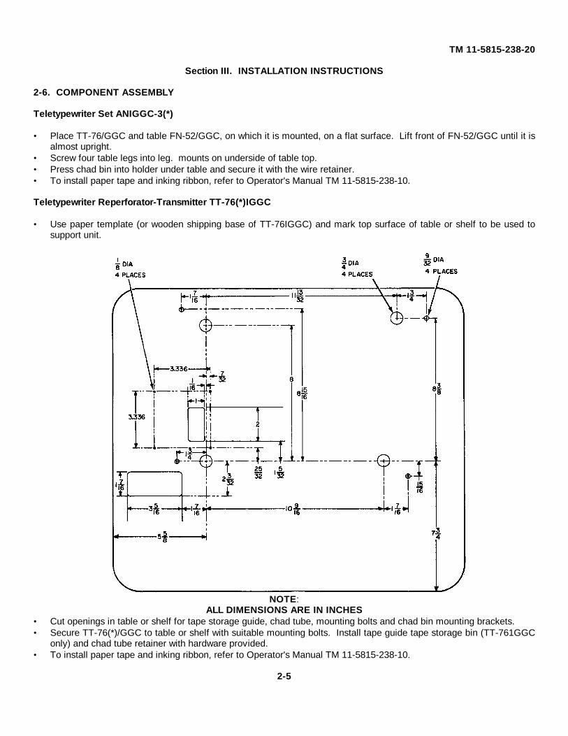
• Use paper template (or wooden shipping base of TT-76IGGC) and mark top surface of table or shelf to be used tosupport unit.
NOTE:ALL DIMENSIONS ARE IN INCHES
• Cut openings in table or shelf for tape storage guide, chad tube, mounting bolts and chad bin mounting brackets.• Secure TT-76(*)/GGC to table or shelf with suitable mounting bolts. Install tape guide tape storage bin (TT-761GGC
only) and chad tube retainer with hardware provided.• To install paper tape and inking ribbon, refer to Operator's Manual TM 11-5815-238-10.
2-5
TM 11-5815-238-20
2-7. GROUND AND POWER CONNECTIONS
NOTE
Make sure that AC plug is not plugged into AC outlet.
• Place MOTOR, LIGHT and POWER switches to OFF.• Remove dust cover (see Operator's Manual TM 11-5815-238-10).• Make sure 2-ampere fuses are installed in fuse holder on power supply and terminal unit and in spare fuse clips.
NOTE
The TT-76IGGC uses one fuse in the power input circuit; the TT-76A, B, C/GGC use two fuses. Allequipment is now supplied with 2-ampere fuses disregard any panel markings calling for 1.6-ampere fuses.
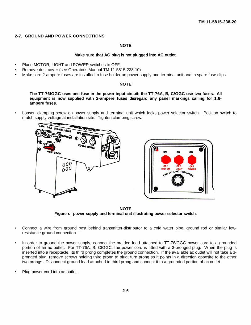
• Loosen clamping screw on power supply and terminal unit which locks power selector switch. Position switch tomatch supply voltage at installation site. Tighten clamping screw.
NOTEFigure of power supply and terminal unit illustrating power selector switch.
• Connect a wire from ground post behind transmitter-distributor to a cold water pipe, ground rod or similar low-resistance ground connection.
• In order to ground the power supply, connect the braided lead attached to TT-76/GGC power cord to a grounded
portion of an ac outlet. For TT-76A, B, CIGGC, the power cord is fitted with a 3-pronged plug. When the plug isinserted into a receptacle, its third prong completes the ground connection. If the available ac outlet will not take a 3-pronged plug, remove screws holding third prong to plug; turn prong so it points in a direction opposite to the othertwo prongs. Disconnect ground lead attached to third prong and connect it to a grounded portion of ac outlet.
• Plug power cord into ac outlet.
2-6
TM 11-5815-238-20
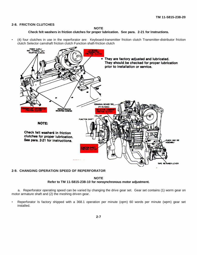
2-8. FRICTION CLUTCHESNOTE
Check felt washers in friction clutches for proper lubrication. See para. 2-21 for Instructions.
• (4) four clutches in use in the reperforator are: Keyboard-transmitter friction clutch Transmitter-distributor frictionclutch Selector camshaft friction clutch Function shaft-friction clutch
2-9. CHANGING OPERATION SPEED OF REPERFORATOR
NOTERefer to TM 11-5815-238-10 for nonsynchronous motor adjustment.
a. Reperforator operating speed can be varied by changing the drive gear set. Gear set contains (1) worm gear onmotor armature shaft and (2) the meshing driven gear.
• Reperforator Is factory shipped with a 368.1 operation per minute (opm) 60 words per minute (wpm) gear setinstalled.
2-7
TM 11-5815-238-20
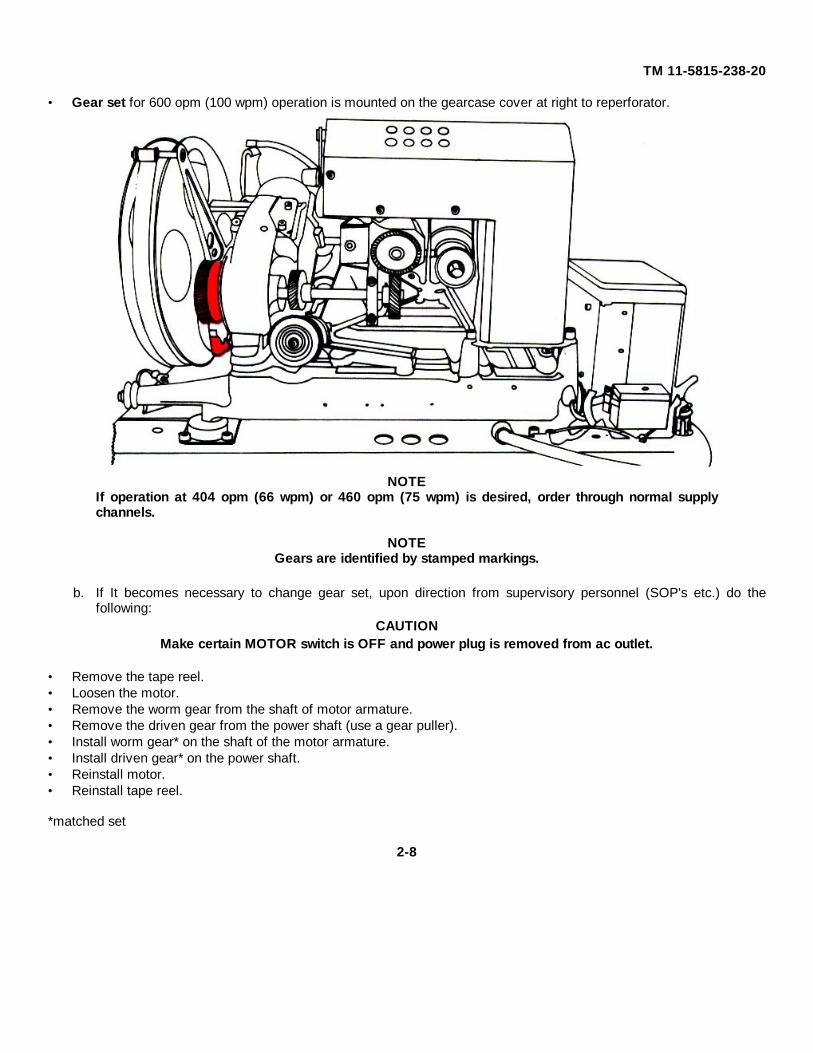
• Gear set for 600 opm (100 wpm) operation is mounted on the gearcase cover at right to reperforator.
NOTEIf operation at 404 opm (66 wpm) or 460 opm (75 wpm) is desired, order through normal supplychannels.
NOTEGears are identified by stamped markings.
b. If It becomes necessary to change gear set, upon direction from supervisory personnel (SOP's etc.) do thefollowing:
CAUTIONMake certain MOTOR switch is OFF and power plug is removed from ac outlet.
• Remove the tape reel.• Loosen the motor.• Remove the worm gear from the shaft of motor armature.• Remove the driven gear from the power shaft (use a gear puller).• Install worm gear* on the shaft of the motor armature.• Install driven gear* on the power shaft.• Reinstall motor.• Reinstall tape reel.
*matched set
2-8
TM 11-5815-238-20
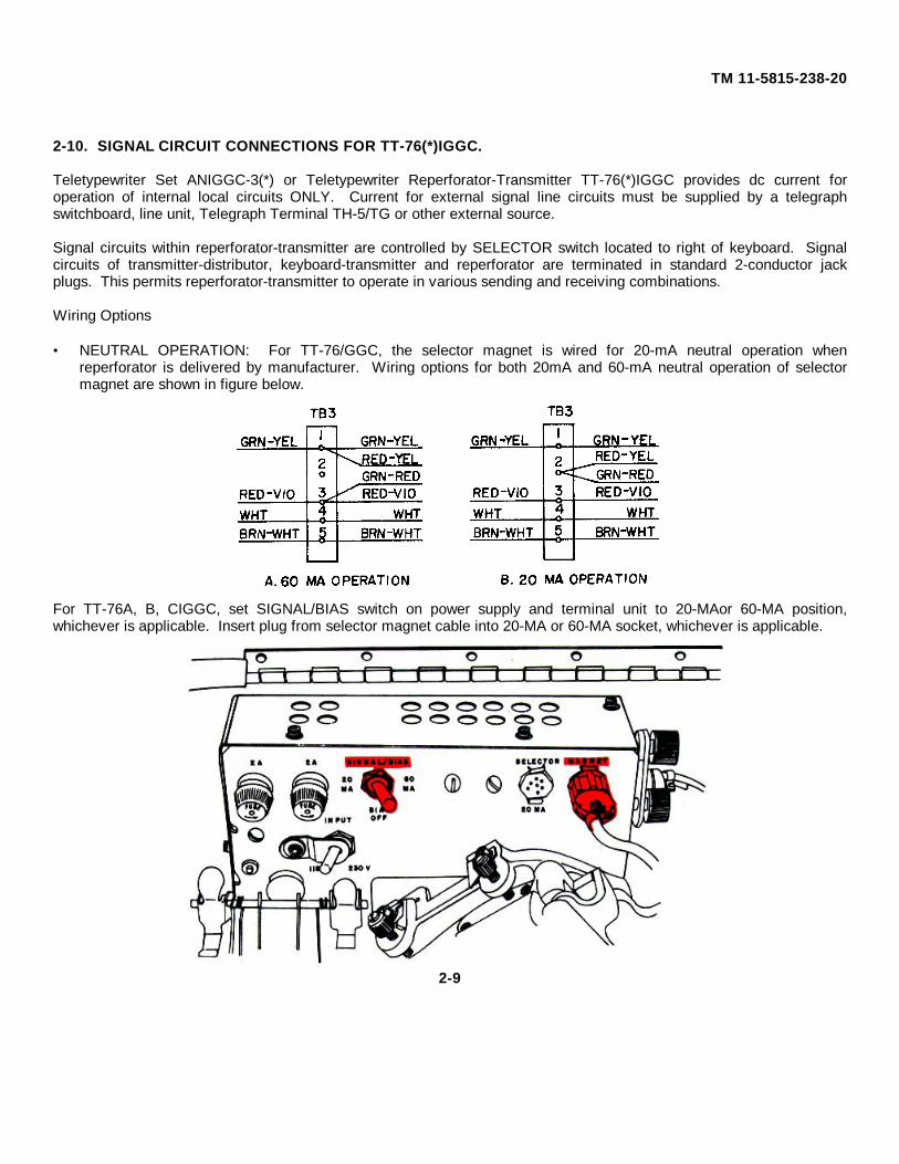
2-10. SIGNAL CIRCUIT CONNECTIONS FOR TT-76(*)IGGC.
Teletypewriter Set ANIGGC-3(*) or Teletypewriter Reperforator-Transmitter TT-76(*)IGGC provides dc current foroperation of internal local circuits ONLY. Current for external signal line circuits must be supplied by a telegraphswitchboard, line unit, Telegraph Terminal TH-5/TG or other external source.
Signal circuits within reperforator-transmitter are controlled by SELECTOR switch located to right of keyboard. Signalcircuits of transmitter-distributor, keyboard-transmitter and reperforator are terminated in standard 2-conductor jackplugs. This permits reperforator-transmitter to operate in various sending and receiving combinations.
Wiring Options
• NEUTRAL OPERATION: For TT-76/GGC, the selector magnet is wired for 20-mA neutral operation whenreperforator is delivered by manufacturer. Wiring options for both 20mA and 60-mA neutral operation of selectormagnet are shown in figure below.
For TT-76A, B, CIGGC, set SIGNAL/BIAS switch on power supply and terminal unit to 20-MAor 60-MA position,whichever is applicable. Insert plug from selector magnet cable into 20-MA or 60-MA socket, whichever is applicable.
2-9
TM 11-5815-238-20
• POLAR OPERATION: Adapt the reperforator for polar operation according to instructions given below:
Polar Receive: For TT-76/GGC, remove and tape separately BRN-WHT wire from terminal 5 and WHT wire fromterminal 4 of terminal block TB3. For TT-76A, B, CIGGC, set 20-BIAS/OFF-60 switch to BIASIOFF andinsert plug from selector magret cable into 60-MA socket.
NOTEThe following items are not supplied with the reperforator-transmitter: 220ohm wire woundresistors, 7,000-ohm center tapped resistor (voltage divider) and a power source capable ofsupplying 120 volts dc at 220 mA.
Polar Send: The transmitter-distributor and keyboard-transmitter can be changed to send polar signals by makingwire changes, at terminal block TB2 of TT76/GGC or TB1 of TT-76A, B, CIGGC and by adding two 220-ohm wire wound resistors, one 7,000-ohm center tapped resistor (voltage divider) and a power sourcecapable of supplying 120 volts dc at 220 mA to the circuit.
a. To make wire changes on transmitter-distributor:• Remove gray plug and cord from terminals 6 and 7 of terminal block.• Connect marking battery to terminal 7.• Connect spacing battery to terminal 8..• Connect one signal line wire to terminal 6.• Connect other signal line wire to midpoint of 7,000-ohm resistor.
b. To make wire changes on keyboard-transmitter:• Remove black plug and cord from terminals 1 and 2 of terminal block.• Connect marking battery to terminal 1.• Connect spacing battery to terminal 3.• Connect one signal line wire to terminal 2.• Connect other signal line wire to midpoint of 7,000-ohm resistor.
2-10
TM 11-5815-238-20
The reperforator-transmitter can be connected for the five different operating combinations listed below. The operatingcapabilities for each combination are described in Operator's Manual TM 11-5815-238-10.
SEND ONLY AND LOCAL PREPARATION OF TAPE
NOTEThe TT-699(*)IGGC and some specially installed TT-76(*)/GGC's do not have red, black or grayplugs.
• Set SELECTOR switch to position 2 (TD SENDLOCAL PUNCH).
• Insert gray plug of transmitter/distributor in SEND
jack of Teletype terminal TH-5/TG or similar device. • Do not use red or black plugs. • Set SELECTOR switch to position 1 (TD SEND TR
SEND RECEIVE). • Insert red plug of reperforator into REC jack of
Teletype terminal TH-5/TG or similar device of oneline.
• Insert black and gray plugs into SEND jacks of line
terminating device of second line.
2-11
TM 11-5815-238-20
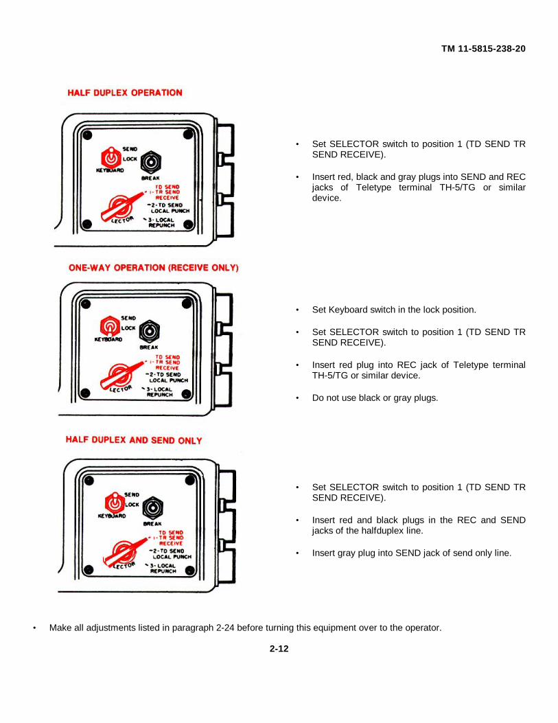
• Set SELECTOR switch to position 1 (TD SEND TRSEND RECEIVE).
• Insert red, black and gray plugs into SEND and REC
jacks of Teletype terminal TH-5/TG or similardevice.
• Set Keyboard switch in the lock position. • Set SELECTOR switch to position 1 (TD SEND TR
SEND RECEIVE). • Insert red plug into REC jack of Teletype terminal
TH-5/TG or similar device. • Do not use black or gray plugs. • Set SELECTOR switch to position 1 (TD SEND TR
SEND RECEIVE). • Insert red and black plugs in the REC and SEND
jacks of the halfduplex line. • Insert gray plug into SEND jack of send only line.
• Make all adjustments listed in paragraph 2-24 before turning this equipment over to the operator.
2-12
TM 11-5815-238-20
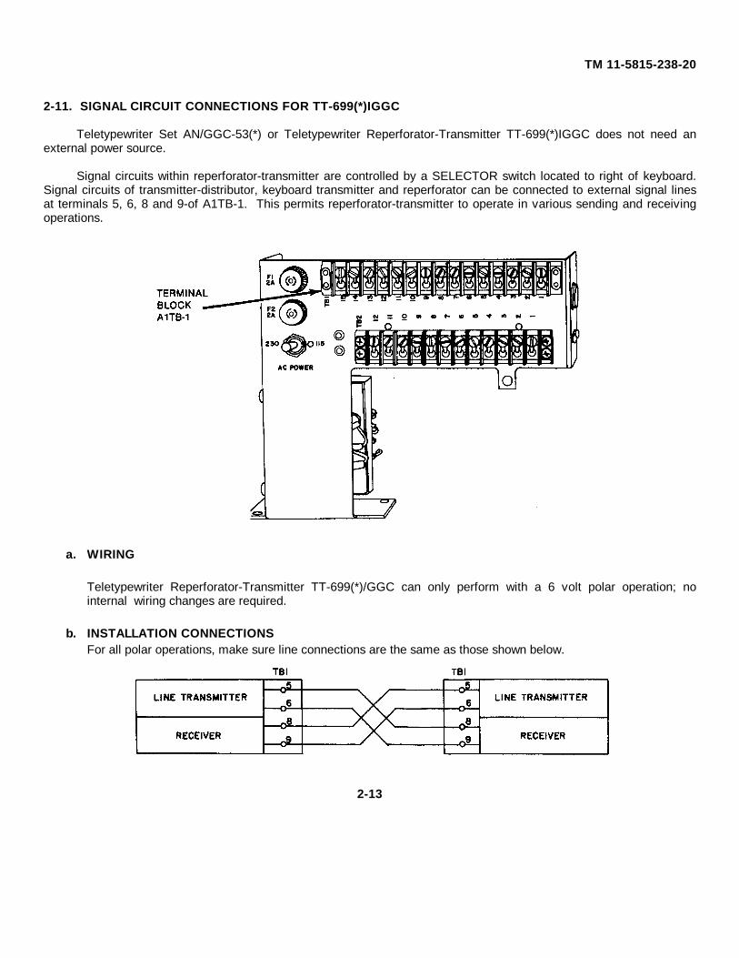
2-11. SIGNAL CIRCUIT CONNECTIONS FOR TT-699(*)IGGC
Teletypewriter Set AN/GGC-53(*) or Teletypewriter Reperforator-Transmitter TT-699(*)IGGC does not need anexternal power source.
Signal circuits within reperforator-transmitter are controlled by a SELECTOR switch located to right of keyboard.Signal circuits of transmitter-distributor, keyboard transmitter and reperforator can be connected to external signal linesat terminals 5, 6, 8 and 9-of A1TB-1. This permits reperforator-transmitter to operate in various sending and receivingoperations.
a. WIRING
Teletypewriter Reperforator-Transmitter TT-699(*)/GGC can only perform with a 6 volt polar operation; nointernal wiring changes are required.
b. INSTALLATION CONNECTIONSFor all polar operations, make sure line connections are the same as those shown below.
2-13
TM 11-5815-238-20
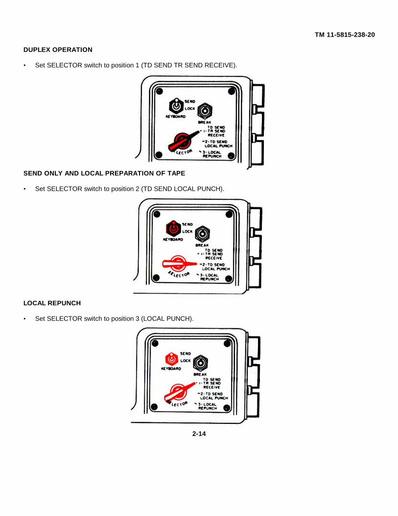
DUPLEX OPERATION
• Set SELECTOR switch to position 1 (TD SEND TR SEND RECEIVE).
SEND ONLY AND LOCAL PREPARATION OF TAPE
• Set SELECTOR switch to position 2 (TD SEND LOCAL PUNCH).
LOCAL REPUNCH
• Set SELECTOR switch to position 3 (LOCAL PUNCH).
2-14
TM 11-5815-238-20
Section IV. PREVENTIVE MAINTENANCE CHECKS AND SERVICES (PMCS)
2-12. GENERALThe following information is for MONTHLY preventive maintenance checks and services (PMCS) of Teletypewriter SetsANIGGC-3(*) and ANIGGC-53(*), and Teletypewriter Reperforator Transmitters TT-76(*)/GGC and TT-699(*)IGGC.Monthly PMCS should be performed every 30 calendar days of 8 hour-per-day operation. If the equipment is operated16 hours-per-day, check it at 15-day intervals. Monthly PMCS should be done if the ANIGGC-3(*), ANIGGC-53(*), TT-76(*)/GGC, or TT-699(*)/GGC is in standby (ready for immediate operation) condition, but is not needed if the equipmentis in limited storage. Maintenance forms and records to be used and maintained on this equipment are specified in TM38-750. Perform all checks and services in sequence listed in Table 2-1.
a. Tools, Test Equipment and Material needed for Organizational level PMCS.
• All the tools you need for PMCS on the AN/GGC-3(*), AN/GGC-53(*), TT-76(*)IGGC or TT-699(*) are in ToolEquipment TE-50B. For expendable supplies and materials, refer to Appendix C.
Fumes of TRICHLOROTRIFLUOROETHANE are poisonous. Provide adequate ventilationwhenever you use TRICHLOROTRIFLUOROETHANE. Do not use solvent near heat or open flame.TRICHLOROTRIFLUOROETHANE will not burn, but heat changes the gas into poisonous, irritatingfumes. DO NOT breathe the fumes or vapors TRICHLOROTRIFLUOROETHANE dissolvesnatural skin oils. DO NOT get the solvent on your skin. Use gloves, sleeves and an apron whichthe solvent cannot penetrate. If the solvent is taken internally, see a doctor.
b. PMCS Table (Table 2-1).
ROUTINE SERVICES
Routine services are a collection of checks and observations performed by the operator at all times. Routine servicesare not listed in the preventive maintenance checks and services table, in order to separate the nonoperational from theoperational services. You should perform the following routines as necessary.
• Clean• Dust• Wash• Check for cut or frayed cables• Check for dented, bent, or broken components• Check for rusting
• Check controls for smooth operation • Check for loose nuts, bolts, and connectors• Check for completeness of equipment
2-15
TM 11-5815-238-20
• If you find any damage during PMCS, refer to the TROUBLESHOOTING TABLE (Table 2-2) or MAINTENANCEPROCEDURES in this manual for instructions on how to correct it. A higher category of maintenance may berequired.
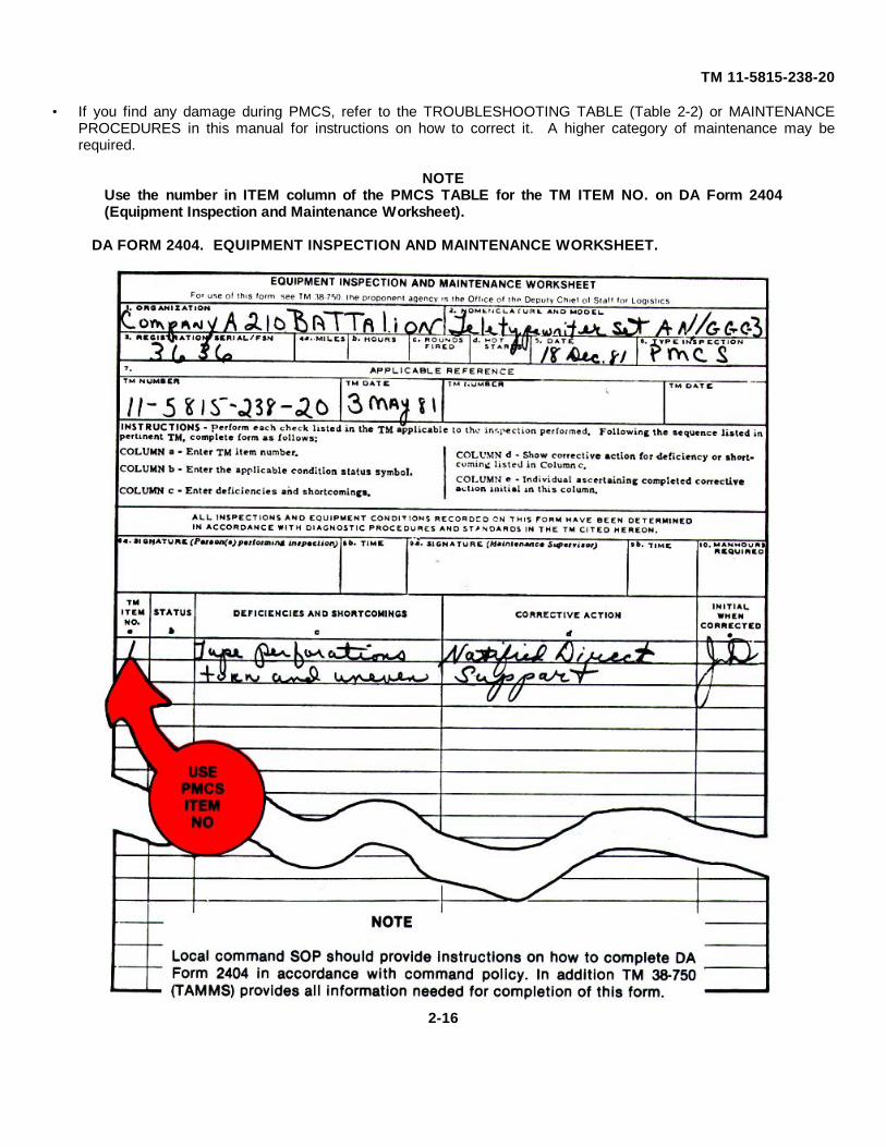
NOTEUse the number in ITEM column of the PMCS TABLE for the TM ITEM NO. on DA Form 2404(Equipment Inspection and Maintenance Worksheet).
DA FORM 2404. EQUIPMENT INSPECTION AND MAINTENANCE WORKSHEET.
2-16
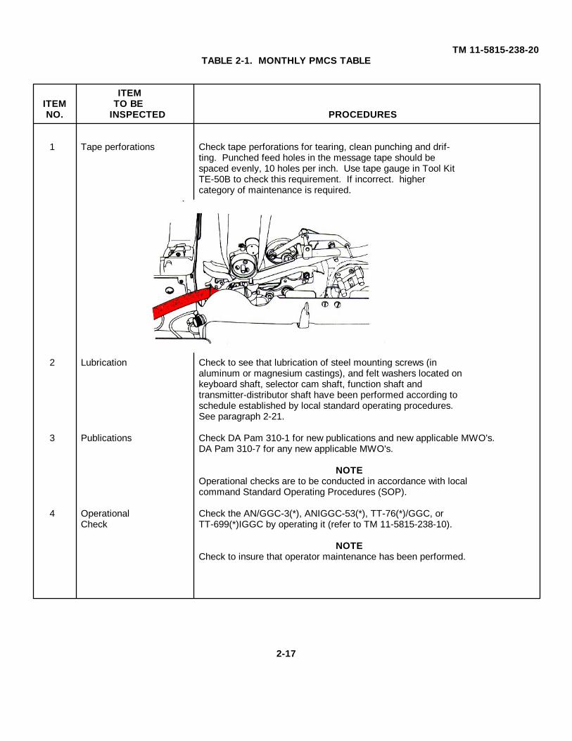
TM 11-5815-238-20TABLE 2-1. MONTHLY PMCS TABLE
ITEMITEM TO BENO. INSPECTED PROCEDURES
1 Tape perforations Check tape perforations for tearing, clean punching and drif-ting. Punched feed holes in the message tape should bespaced evenly, 10 holes per inch. Use tape gauge in Tool KitTE-50B to check this requirement. If incorrect. highercategory of maintenance is required.
2 Lubrication Check to see that lubrication of steel mounting screws (inaluminum or magnesium castings), and felt washers located onkeyboard shaft, selector cam shaft, function shaft andtransmitter-distributor shaft have been performed according toschedule established by local standard operating procedures.See paragraph 2-21.
3 Publications Check DA Pam 310-1 for new publications and new applicable MWO's.DA Pam 310-7 for any new applicable MWO's.
NOTEOperational checks are to be conducted in accordance with localcommand Standard Operating Procedures (SOP).
4 Operational Check the AN/GGC-3(*), ANIGGC-53(*), TT-76(*)/GGC, orCheck TT-699(*)IGGC by operating it (refer to TM 11-5815-238-10).
NOTECheck to insure that operator maintenance has been performed.
2-17
TM 11-5815-238-20
Section V. TROUBLESHOOTING2-13. GENERAL
Troubleshooting at the Organizational Maintenance level requires you to locate any trouble as quickly as possible.
Once trouble is located, repair or replace the part if you are authorized to do so or determine if a higher category ofmaintenance is required. Repairs by Organizational Maintenance are limited to tools, test equipment and replacementparts allocated to that level by the Maintenance Allocation Chart (MAC) located in Appendix B of this manual.
2-14. VISUAL INSPECTION
• Equipment failure or improper operation is usually caused by one or more of the visible faults listed below:
1. Improperly connected power cord.2. Burned out fuse in power supply and terminal unit.3. Worn, broken, burned out or disconnected cord or plug.4. Wires broken by too much vibration.5. Loose ground connection, particularly in dc systems using a simplex line.6. Worn or, damaged mechanical part.7. Power selector switch not set to match ac power.8. Inadequate supply of paper tape, or improper positioning of tape through guides, under type wheel and through
punch and die assembly.9. Improper positioning of inking ribbon around spools and rollers or not passed through guide slots.
10. Power switch not turned ON.
• Visually check as much of the line system as possible for obvious trouble, especially lines not connected into properfacilities for type of operation desired.
NOTEBefore using Troubleshooting Table (Table 2-2), check your work order and talk to the Operator, ifpossible, for a description of symptoms if trouble occurred while equipment was in operation.
2-15. TROUBLESHOOTING TABLE (Table 2-2)
Table 2-2 lists common problems that may occur during operation or maintenance of AN/GGC-3(*) or AN/GGC-53(*).Follow these steps to use Table 2-2:• Find the problem under MALFUNCTION.• Check for possible causes of the problem under TEST OR INSPECTION.• Use the procedures under CORRECTIVE ACTION to correct the problem.
2-18
TM 11-5815-238-20NOTE
The procedures in Table 2-2 assume that the teletypewriter is connected to a signal line or the localtest circuit (see para 2-11), that a good fuse is properly inserted in the fuse holder and that papertape has been properly loaded in the teletypewriter.
• This manual cannot list all troubles that may occur, nor everything to check, nor all possible procedures to correcttroubles listed. If trouble is not listed in Table 2-2 or is not corrected by the procedures under CORRECTIVEACTION, notify your supervisor or next higher level of maintenance.
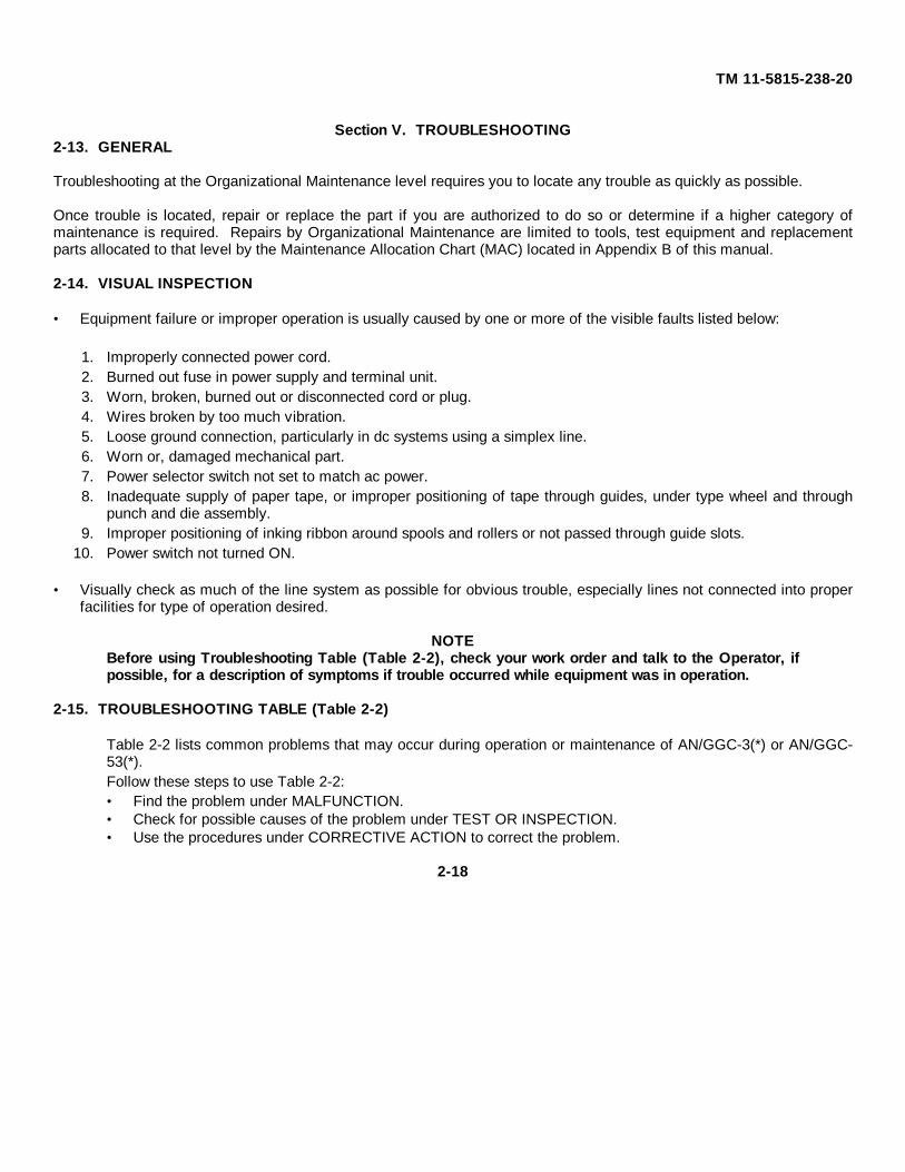
• Set KEYBOARD switch to SEND position. • Set SELECTOR switch to position 3 (LOCAL REPUNCH).
TT-76(*)/GGC teletypewriter transmitter contacts are now placed in series with the selector magnet and a local dcsupply. TT-699(*)/GGC teletypewriter contacts are now placed in series with each other and the input from the linetransmitter module. The local machine reperforator can now be operated with signals received directly from transmitter-distributor or key board transmitter.
NOTEIf the trouble still exists after Troubleshooting, check for it in the line circuit or at the distantteletypewriter.
2-19
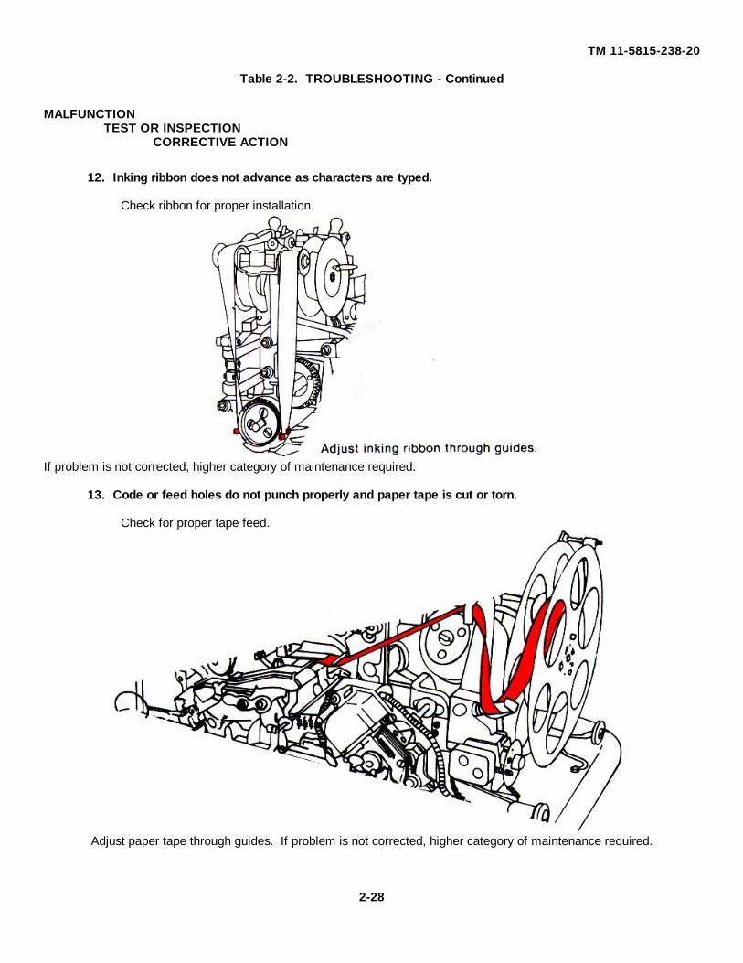
TM 11-5815-238-20Table 2-2. TROUBLESHOOTING
MALFUNCTIONTEST OR INSPECTION
CORRECTIVE ACTION
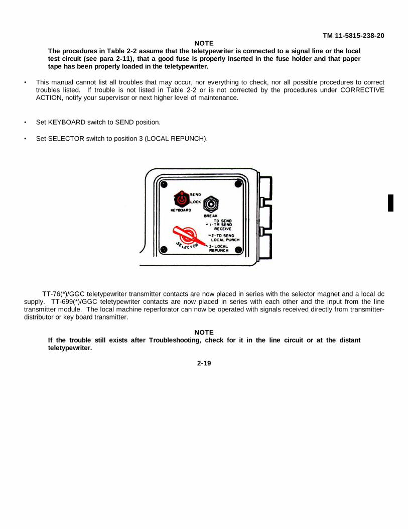
1. Copy light does not light up.
NOTEPOWER switch ON for all procedures. Lift keyboard guard assembly to check connections. (allmodels except TT-76/GGC, TT-699/GGC which are secured to base plate by machine screws andwashers)
Step 1. Be sure unit is plugged in.
Step 2. Be sure LIGHT switch is set to ON.
Step 3. If LIGHT switch is set to ON, check lamp forburned out bulb and be sure switch is free from binding.
Step 4. Check rear of light switch for loose, frayed orbroken wires.
If light bulb is in working order, higher category of maintenance required.
2-20
TM 11-5815-238-20Table 2-2. TROUBLESHOOTING - Continued
MALFUNCTIONTEST OR INSPECTION
CORRECTIVE ACTION
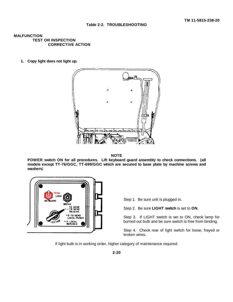
2. Motor does not start.
Step 1. Check for blown fuses, broken wires, defective power switch.
Replace blown fuses, report all other defects to next higher maintenance level.
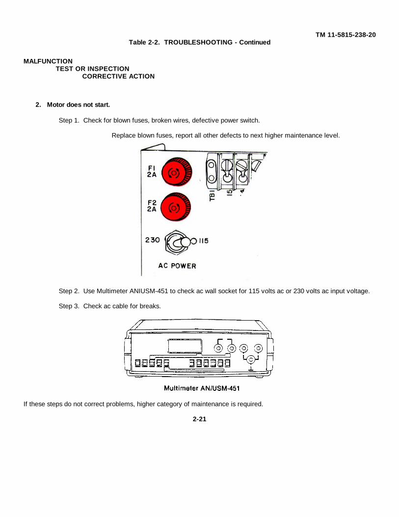
Step 2. Use Multimeter ANIUSM-451 to check ac wall socket for 115 volts ac or 230 volts ac input voltage.
Step 3. Check ac cable for breaks.
If these steps do not correct problems, higher category of maintenance is required.
2-21
TM 11-5815-238-20Table 2-2. TROUBLESHOOTING - Continued
MALFUNCTIONTEST OR INSPECTION
CORRECTIVE ACTION
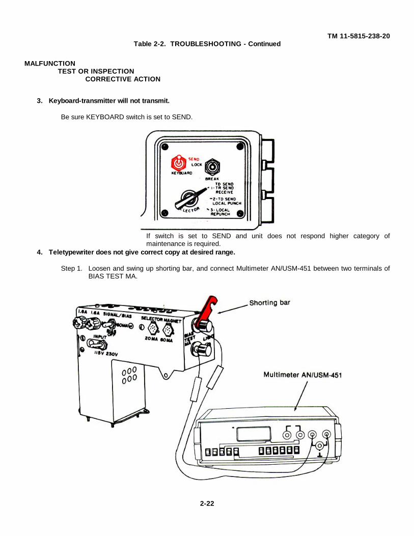
3. Keyboard-transmitter will not transmit.
Be sure KEYBOARD switch is set to SEND.
If switch is set to SEND and unit does not respond higher category ofmaintenance is required.
4. Teletypewriter does not give correct copy at desired range.
Step 1. Loosen and swing up shorting bar, and connect Multimeter AN/USM-451 between two terminals ofBIAS TEST MA.
2-22
TM 11-5815-238-20Table 2-2. TROUBLESHOOTING- Continued
MALFUNCTIONTEST OR INSPECTION
CORRECTIVE ACTION
Step 2. Be sure SIGNAL BIAS switch in 20-MA position to check for 20 mA reading and SELECTOR MAGNET plug is in 20 mA position. Change to 60-MA positions and take 60 mA readings.
Step 3. Current in bias circuit should read 12.25 mA if selector plug is in 60-MA jack or 8.75 mA if selector plug is in 20-MA jack. Refer to TM 11-5815-238-10.
Adjust bias. Refer to TM 11-5815-238-10 (TT-76/GGC) or paragraph 2-24, this TM (TT-76A, B orC/GGC).
If meter still does not equal the values given in Step 3. higher category of maintenance required.
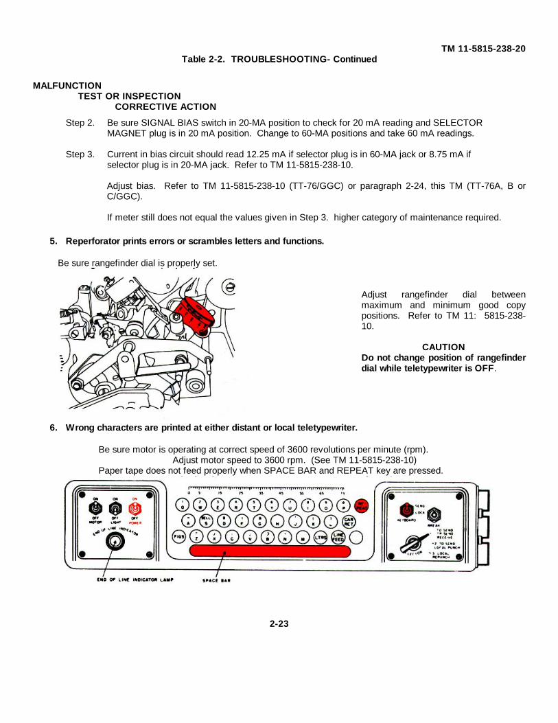
5. Reperforator prints errors or scrambles letters and functions.
Be sure rangefinder dial is properly set.
Adjust rangefinder dial betweenmaximum and minimum good copypositions. Refer to TM 11: 5815-238-10.
CAUTIONDo not change position of rangefinderdial while teletypewriter is OFF.
6. Wrong characters are printed at either distant or local teletypewriter.
Be sure motor is operating at correct speed of 3600 revolutions per minute (rpm).Adjust motor speed to 3600 rpm. (See TM 11-5815-238-10)
Paper tape does not feed properly when SPACE BAR and REPEAT key are pressed.
2-23
TM 11-5815-238-20Table 2-2. TROUBLESHOOTING - Continued
MALFUNCTIONTEST OR INSPECTION
CORRECTIVE ACTION
Step 1. Check for bent reel.
Step 2. Be sure paper feeds smoothly into tape chute.
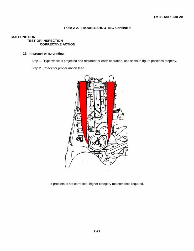
If problem is not corrected, higher category of maintenance required.7. END-OF-LINE INDICATOR lamp does not light on operation of 66th character.
Step 1. Check lamp for burned out bulb and contacts.Step 2. Check lamp socket.Step 3. Check rear of switch wire connections. Replace lamp if necessary.
2-24
TM 11-5815-238-20Table 2-2. TROUBLESHOOTING - Continued
MALFUNCTIONTEST OR INSPECTION
CORRECTIVE ACTION
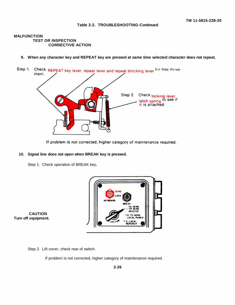
8. END-OF-LINE INDICATOR lamp does not go out when CAR. RET. key is pressed.
Check character counter freely returns to left side after CAR RET key is pressed.
If it does not freely return, higher category of maintenance required.
5. LUBRICATING• Steel setscrews in aluminum and magnesium castings.• Felt washers (friction clutches).
6. ADJUSTMENT• Motor speed• Rangefinder dial• Bias potentiometer (TT-76/GGC ONLY)
NOTEAll procedures are the same for TT-76(*)/GGC as for TT-699(*)/GGC.
2-18. TOOLS, TEST EQUIPMENT AND MATERIAL REQUIRED OF ORGANIZATIONAL MAINTENANCE.• All tools you will need for maintenance on ANIGGC-3(*) and AN/GGC-53(*) are in Tool Equipment, TE-
WARNINGFumes of TRICHLOROTRIFLUOROETHANE are poisonous. Provide adequate ventilationwhenever you use TRICHLOROTRIFLUOROETHANE. Do not use solvent near heat or open flame.TRICHLOROTRIFLUOROETHANE will not burn, but heat changes the gas into poisonous, irritatingfumes. DO NOT breathe the fumes or vapors TRICHLOROTRIFLUOROETHANE dissolves naturalskin oils. DO NOT get the solvent on your skin. Use gloves, sleeves and an apron which thesolvent cannot penetrate. If the solvent is taken internally, see a doctor.
2-19. INSPECTION
Be sure all equipment is properly installed. Check for proper positioning and tightening of all nuts, bolts and washers.
2-29
TM 11-5815-238-20
NOTEIn order to perform the following cleaning procedures, follow the instructions for removal andreplacement of dust covers in Operator's Manual TM 11-5815-238-10.
2-20. CLEANING
a. Internal Mechanical Assemblies.
Use a clean, lint-free cloth dampened (not wet) with cleaning solvent (SD) to remove dust or dirt. Wipe dry.
b. Electrical Contact Surfaces.
WARNINGFumes of TRICHLOROTRIFLUOROETHANE are poisonous. Provide adequate ventilationwhenever you use TRICHLOROTRIFLUOROETHANE. Do not use solvent near heat or open flame.TRICHLOROTRIFLUOROETHANE will not burn, but heat changes the gas Into poisonous, irritatingfumes. DO NOT breathe the fumes or vapors TRICHLOROTRIFLUOROETHANE dissolves naturalskin oils. DO NOT get the solvent on your skin. Use gloves, sleeves and an apron which thesolvent cannot penetrate. If the solvent is taken internally, see a doctor.
Use a clean, lint-free cloth or a brush dampened (not wet) with Trichlorotrifluoroethane to remove dust and dirtfrom electrical contacts. Wipe dry with another clean, lint-free cloth.
2-21. LUBRICATING
a. Friction Clutches (4) see paragraph 2-8.
• Check for proper lubrication prior to installation placing into service.• If lubrication is required, apply 10 to 15 drops of oil (NSN 9150-00-223-4129) around outer edge of each felt
washer.• Wipe off excess with clean cloth.
b. Steel Mounting Screws (magnesium and aluminum casting)
• Lightly oil.
2-22. TESTING
Use Multimeter ANIUSM-451 to test dc voltage input of TT-76(*)/GGC or TT-699(*)/GGC; it should be 115 vac or 230vac.
2-23. PAINTING
Remove rust and corrosion from metal surfaces by lightly sanding with fine sandpaper. Brush two thin coats of theproper paint on bare metal to protect it from further corrosion. Refer to applicable procedures in TB 43-0118.
2-30
TM 11-5815-238-20
2-24. ADJUSTMENTS
Motor speed and Rangefinder adjustments for all models of teletypewriter-reperforator, and Bias adjustment forTT-76/GGC are found in TM 11-5815-238-10.
NOTEIf reperforator is equipped with a synchronous motor, motor speed adjustment not required.
Bias Potentiometer Adjustment for TT-76AIGGC and later models
NOTEMake the following adjustment only when equipment is operating in a neutral circuit, since biaswindings are not used for polar operation.
• Set keyboard SEND LOCK switch to the SEND position and the SELECTOR SWITCH to position 3 (LOCALREPUNCH).
• Shut off equipment - switches.• Loosen the strap across the BIAS TEST MA terminal on the power supply and terminal unit and move to up
position.• Power switch on position.• Connect a Multimeter in series with the terminal post. Refer to Troubleshooting Table 2-2 Trouble No. 4
Step 1.• Loosen the locknut on the shaft of the bias potentiometer and turn the shaft with a screwdriver until a reading
of 8.75 mA is obtained for 20 mA operation or a reading of 12.25 mA is obtained for 60-mA operation.• Tighten the locknut and recheck the adjustment.• Turn off power switch.• Disconnect the multimeter and reconnect the strap between the BIAS TEST MA terminals.• Readjust the range. Refer to TM 11-5815-238-10.
2-31
TM 11-5815-238-20
Section VII. PREPARATION FOR STORAGE AND SHIPMENT
2-25. SECURITY PROCEDURES
Refer to security procedures listed in the Standard Operating Procedures for the operating organization.
2-26. DISASSEMBLY OF EQUIPMENT
a. Teletypewriter Set.
• Disconnect signal lines and power cords.• Remove chad bin.• Remove legs from table.• Remove roll of paper tape from tape reel.
b. Teletypewriter Reperforator-Transmitter.
• Disconnect signal lines and power cords.• Remove chad bin and its mounting equipment, tape guide, tape storage bin assembly and its mounting
equipment.• Remove mounting equipment attaching reperforator-transmitter to table and remove reperforator-transmitter.
2-27. TYPES OF STORAGE
• Short term (administrative) = 1 to 45 days. All equipment in administrative storage must be able to be madeready within 24 hours for use on a mission. Before placing any item in administrative storage, perform thenext scheduled PMCS and correct or repair any deficiencies you find. The administrative storage site shouldprovide required protection from extreme weather conditions and allow you to reach the equipment for visualinspections or exercises when applicable.
• Intermediate = 46 to 180 days.• Long term or flyable = no time limit.
2-32
TM 11-5815-238-20
APPENDIX A
REFERENCES
A-1. INTRODUCTION
Following is a list of all forms, technical bulletins and technical manuals referenced in this manual.
A-2. FORMS
Equipment Inspection and Maintenance Worksheet ............................................DA Form 2404
Quality Deficiency Report ....................................................................................Form SF 368Recommended Changes to Equipment Technical Manuals .................................DA Form 2028-2Recommended Changes to Publications and Blank Forms ..................................DA Form 2028
A-3. TECHNICAL BULLETINS
Field Instructions for Painting and Preserving Electronics CommandEquipment Including Camouflage Pattern Painting of ElectronicEquipment Shelter ..............................................................................................TB 43-0118
A-4. TECHNICAL MANUALS
Operator's Manual: Teletypewriter Sets
AN/GGC-3, AN/GGC-3A, AN/GGC-53, AN/GGC-53A (NSN5815-01-017-0956) and Teletypewriter Reperforator-Transmitters TT-76/GGC, TT-76A/GGC, TT-76BIGGC, TT-76C/GGC, TT-6991GGC, TT-699A/GGC, TT-699B/GGC, (NSN 5815-01-017-9166) and TT-699C/GGC(NSN 5815-01-017-9166) ....................................................................................TM 11-5815-238-10Organizational Maintenance Repair Parts and Special Tools List:Teletypewriter Sets AN/GGC-3, AN/GGC-3A, ANIGGC-53, ANIGGC-53A(NSN 5815-01,-017-0956) and Teletypewriter Reperforator-TransmittersTT-76/GGC, TT-76AIGGC, TT-76B/GGC, TT-76C/GGC, TT-6991GGC, TT-699A/GGC, TT-699B/GGC (NSN 5815-01-017-9166) and TT-699CIGGC(NSN 5815-01-017-9166) ....................................................................................TM 11-5815-238-20POperator's, Organizational, Direct Support Maintenance Manual:Multimeter AN/USM-451 (NSN 6625-01-060-6804) .............................................TM 11-6625-2953-14Procedures for Destruction of Electronic Materiel to Prevent Enemy Use(Electronics Command ........................................................................................TM 750-244-2The Army Maintenance Management System (TAM MS) ....................................TM 38-750
A-5. MISCELLANEOUS PUBLICATIONS
Consolidated Index of Army Publications and Blank Forms .................................DA Pam 310-1
Section I. INTRODUCTIONB-1. GeneralThis appendix provides a summary of the maintenance operations for AN/GGC-3(*) or AN/GGC-53(*). It authorizescategories of maintenance for specific maintenance functions on repairable items and components and the tools andequipment required to perform each function. This appendix may be used as an aid in planning maintenance operations.
B-2. Maintenance Function
Maintenance functions will be limited to and defined as follows:
a. Inspect. To determine the serviceability of oan item by comparing its physical, mechanical, and/or electricalcharacteristics with established standards through examination.
b. Test. To verify serviceability and to detect incipient failure by measuring the mechanical or electricalcharacteristics of an item and comparing those characteristics with prescribed standards.
c. Service. Operations required periodically to keep an item in proper operating condition, i.e., to clean(decontaminate), to preserve, to drain, to point, or to replenish fuel, lubricants, hydraulic fluids, or compressed airsupplies.
d. Adjust. To maintain, within prescribed limits, by bringing into proper or exact position, or by setting the operatingcharacteristics to the specified parameters.
e. Align. To adjust specified variable elements of an item to bring about optimum or desired performance.f. Calibrate. To determine and cause corrections to be made or to be made or to be adjusted on instruments or
test measuring and diagnostic equipments used in precision measurement. Consists of comparisons of two instruments,one of which is a certified standard of known accuracy, to detect and adjust any discrepancy in the accuracy of theinstrument being compared.
g. Install. The act of emplacing, seating, or fixing into position an item, part, module (component or assembly) in amanner to allow the proper functioning of the equipment or system.
h. Replace. The act of substituting a serviceable like type part, subassembly, or module (component or assembly)for an unserviceable counterpart.
i. Repair. The application of maintenance service (inspect, test, service, adjust, align, calibrate, replace) or othermaintenance actions (welding, grinding, riveting, straightening, facing, remachining, or resurfacing) to restoreserviceability to an item by correcting specific damage, fault, malfunction, or failure in a part, subassembly, module(component or assembly), end item, or system.
j. Overhaul. That maintenance effort (service/action) necessary to restore an item to a completelyserviceable/operational condition as prescribed by maintenance standards (i.e., DMWR) in appropriate technicalpublications. Overhaul is normally the highest degree of maintenance performed by the Army. Overhaul does notnormally return an item to like new condition.
k. Rebuild. Consists of those services/actions necessary for the restoration of unserviceable equipment to a likenew condition in accordance with original manufacturing standards. Rebuild is the highest degree of materielmaintenance applied to Army equipment. The rebuild operation includes the act of returning to zero those agemeasurements (hours, miles, etc.) considered in classifying Army equipment/components.
B-3. Column Entries
a. Column 1, Group Number. Column 1 lists group numbers, the purpose of which is to identify components,assemblies, subassemblies, and modules with the next higher assembly.
b. Column 2, Component/Assembly. Column 2 contains the noun names of components, assemblies,subassemblies, and modules for which maintenance is authorized.
B-1
TM 11-5815-238-20
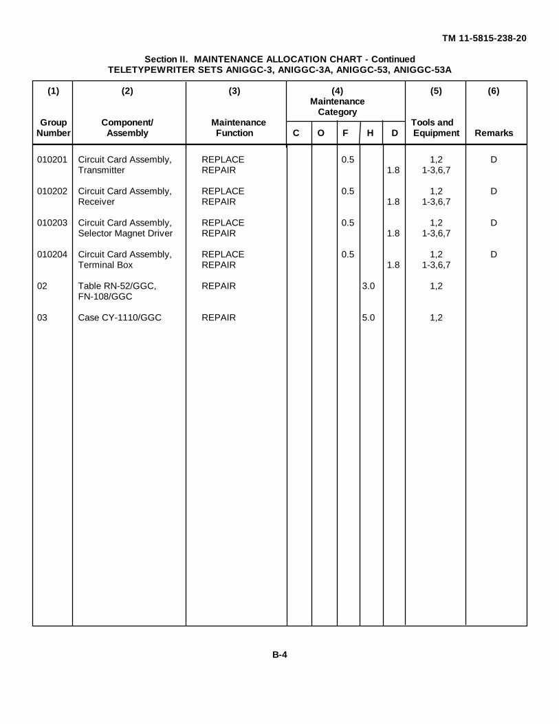
c. Column 3, Maintenance Functions. Column 3 lists the functions to be performed on the item listed in column 2.When items are listed without maintenance functions, it is solely for purpose of having the group numbers in the MACand RPSTL coincide.
d. Column 4, Maintenance Category. Column 4 specifies, by the listing of a "work time" figure in the appropriatesubcolumn(s), the lowest level of maintenance authorized to perform the function listed in column 3. This figurerepresents the active time required to perform that maintenance function at the indicated category of maintenance. If thenumber or complexity of the tasks within the listed maintenance function vary at different maintenance categories,appropriate "work time" figures will be shown for each category. The number of task-hours specified by the "work time"figure represents the average time required to restore an item (assembly, subassembly, component, module, end item orsystem) to a serviceable condition under typical field operating conditions. This time includes preparation time,troubleshooting time, and quality assurance/quality control time in addition to the time required to perform the specifictasks identified for the maintenance functions authorized in the maintenance allocation chart. Subcolumns of column 4are as follows:
C - Operator/CrewO - OrganizationalF - Direct SupportH - General SupportD - Depot
e. Column 5, Tools and Equipment. Column 5 specifies by code, those common tool sets (not individual tools) andspecial tools, test, and support equipment required to perform the designated function.
f. Column 6, Remarks. Column 6 contains an alphabetic code which leads to the remarks in section IV, Remarks,which is pertinent to the item opposite the particular code.
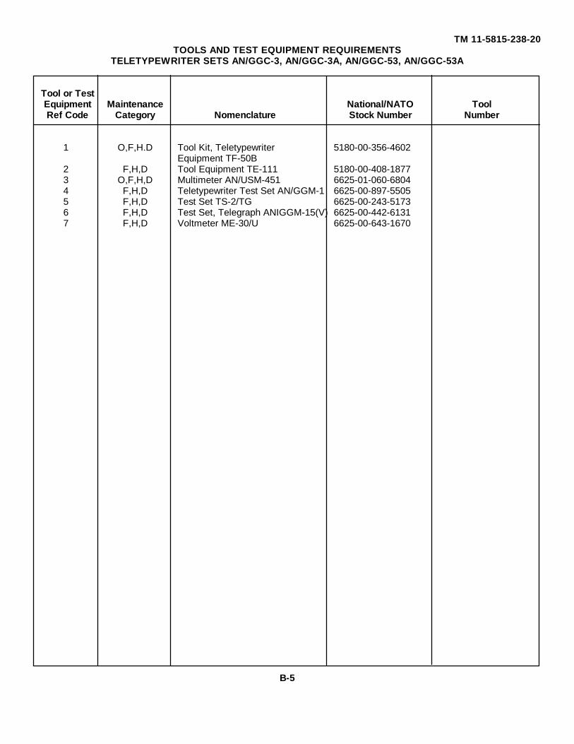
B-4. Tool and Test Equipment Requirements (Sect. III)
a. Tool or Test Equipment Reference Code. The numbers in this column coincide with the numbers used in thetools and equipment column of the MAC. The numbers indicate the applicable tool or test equipment for themaintenance functions.
b. Maintenance Category. The codes in this column indicate the maintenance category allocated the tool or testequipment.
c. Nomenclature. This column lists the noun name and nomenclature of the tools and test equipment required toperform the maintenance functions.
d. National/NA TO Stock Number. This column lists the National/NATO stock number of the specific tool or testequipment.
e. Tool Number. This column lists the manufacturer's part number of the tool followed by the Federal Supply Codefor manufacturers (5-digit) in parentheses.
B-5. Remarks (Sect. IV)
a. Reference Code. This code refers to the appropriate item in section II, column 6.b. Remarks. This column provides the required explanatory information necessary to clarify items appearing in
section II.
B-2
TM 11-5815-238-20
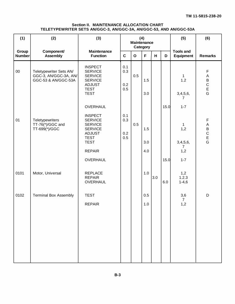
Section II. MAINTENANCE ALLOCATION CHARTTELETYPEWRITER SETS AN/GGC-3, AN/GGC-3A, AN/GGC-53, AND AN/GGC-53A
(1) (2) (3) (4) (5) (6)Maintenance
CategoryGroup Component/ Maintenance Tools and
Number Assembly Function C O F H D Equipment Remarks
INSPECT 0.100 Teletypewriter Sets AN/ SERVICE 0.3 F
GGC-3, AN/GGC-3A, AN/ SERVICE 0.5 1 AGGC-53 & AN/GGC-53A SERVICE 1.5 1.2 B
ADJUST 0.2 CTEST 0.5 ETEST 3.0 3,4,5,6, G
7
OVERHAUL 15.0 1-7
INSPECT 0.101 Teletypewriters SERVICE 0.3 F
TT-76(*)/GGC and SERVICE 0.5 1 ATT-699(*)/GGC SERVICE 1.5 1,2 B
2 F,H,D Tool Equipment TE-111 5180-00-408-18773 O,F,H,D Multimeter AN/USM-451 6625-01-060-68044 F,H,D Teletypewriter Test Set AN/GGM-1 6625-00-897-55055 F,H,D Test Set TS-2/TG 6625-00-243-51736 F,H,D Test Set, Telegraph ANIGGM-15(V) 6625-00-442-61317 F,H,D Voltmeter ME-30/U 6625-00-643-1670
B-5
TM 11-5815-238-20
ReferenceCode Remarks
A Replaces fuses, lamps, lens indicatorsB Performs interior service including lubricationC Adjusts Rangefinder and Motor speedD Low-leveled equipment (AN/GGC-53(*) only)E Operational test.F Replenishes paper tape, replaces inking ribbon, empties chad bin.G Performs resistance, voltage and current measurements to determine condition of
circuits. Tests system line up, conducts distortion test.
B-6
TM 11-5815-238-20
APPENDIX C
EXPENDABLE SUPPLIES AND MATERIALS LIST
Section I. INTRODUCTION
C-1. Scope
This appendix lists expendable supplies and materials you will need to operate and maintain the AN/GGC-3(*) orAN/GGC-53(*). These items are authorized to you by CTA 50-970, Expendable Items (Except Medical, Class V, RepairParts, and Heraldic Items).
C-2. Explanation of Columns
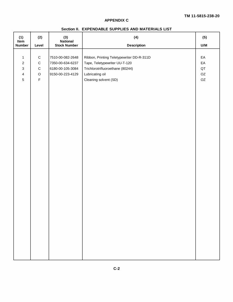
a. Column 1 - Item Number. This number is assigned to the entry in the listing and is referenced in the narrativeinstructions to identify the material (e.g., "Use cleaning compound, item 5, App. D").
b. Column 2 - Level. This column identifies the lowest level of maintenance that requires the listed item.
C - Operator/CrewO - Organizational MaintenanceF - Direct Support MaintenanceH - General Support Maintenance
c. Column 3 - National Stock Number. This is the National stock number assigned to the item; use it to request orrequisition the item.
d. Column 4 - Description. Indicates the Federal item name and, if required, a description to identify the item. Thelast line for each item indicates the part number followed by the Federal Supply Code for Manufacturer (FSCM) inparentheses, if applicable.
e. Column 5 - Unit of Measure (U/M). Indicates the measure used in performing the actual maintenance function.This measure is expressed by a two-character alphabetical abbreviation (e.g., ea, in, pr). If the unit of measure differsfrom the unit of issue, requisition the lowest unit of issue that will satisfy your requirements.
C-1
TM 11-5815-238-20APPENDIX C
Section II. EXPENDABLE SUPPLIES AND MATERIALS LIST
(1) (2) (3) (4) (5)Item National
Number Level Stock Number Description U/M
1 C 7510-00-082-2648 Ribbon, Printing Teletypewriter DD-R-311D EA
2 C 7350-00-634-6237 Tape, Teletypewriter UU-T-120 EA
3 C 6180-00-105-3084 Trichlorotrifluoroethane (80244) QT
4 O 9150-00-223-4129 Lubricating oil OZ
5 F Cleaning solvent (SD) OZ
C-2
TM 11-5815-238-20
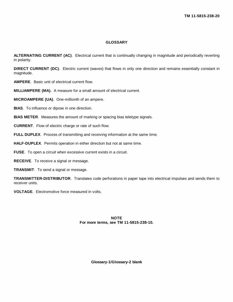
GLOSSARY
ALTERNATING CURRENT (AC). Electrical current that is continually changing in magnitude and periodically revertingin polarity.
DIRECT CURRENT (DC). Electric current (waves) that flows in only one direction and remains essentially constant inmagnitude.
AMPERE. Basic unit of electrical current flow.
MILLIAMPERE (MA). A measure for a small amount of electrical current.
MICROAMPERE (UA). One-millionth of an ampere.
BIAS. To influence or dipose in one direction.
BIAS METER. Measures the amount of marking or spacing bias teletype signals.
CURRENT. Flow of electric charge or rate of such flow.
FULL DUPLEX. Process of transmitting and receiving information at the same time.
HALF-DUPLEX. Permits operation in either direction but not at same time.
FUSE. To open a circuit when excessive current exists in a circuit.
RECEIVE. To receive a signal or message.
TRANSMIT. To send a signal or message.
TRANSMITTER-DISTRIBUTOR. Translates code perforations in paper tape into electrical impulses and sends them toreceiver units.
VOLTAGE. Electromotive force measured in volts.
NOTEFor more terms, see TM 11-5815-238-10.
Glossary-1/GIossary-2 blank
TM 11-5815-238-20
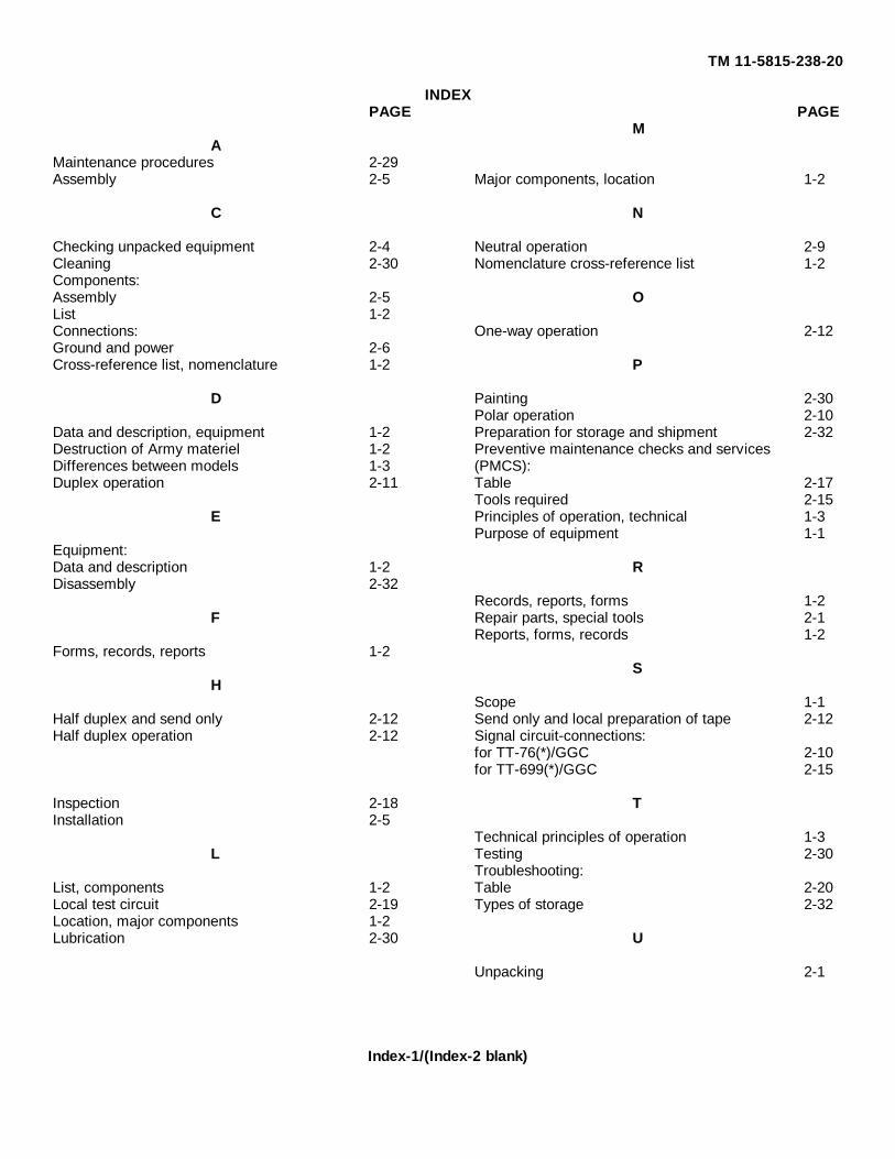
INDEXPAGE PAGE
MA
Maintenance procedures 2-29Assembly 2-5 Major components, location 1-2
C N
Checking unpacked equipment 2-4 Neutral operation 2-9Cleaning 2-30 Nomenclature cross-reference list 1-2Components:Assembly 2-5 OList 1-2Connections: One-way operation 2-12Ground and power 2-6Cross-reference list, nomenclature 1-2 P
D Painting 2-30Polar operation 2-10
Data and description, equipment 1-2 Preparation for storage and shipment 2-32Destruction of Army materiel 1-2 Preventive maintenance checks and servicesDifferences between models 1-3 (PMCS):Duplex operation 2-11 Table 2-17
Tools required 2-15E Principles of operation, technical 1-3
Purpose of equipment 1-1Equipment:Data and description 1-2 RDisassembly 2-32
Records, reports, forms 1-2F Repair parts, special tools 2-1
Reports, forms, records 1-2Forms, records, reports 1-2
SH
Scope 1-1Half duplex and send only 2-12 Send only and local preparation of tape 2-12Half duplex operation 2-12 Signal circuit-connections:
for TT-76(*)/GGC 2-10for TT-699(*)/GGC 2-15
Inspection 2-18 TInstallation 2-5
Technical principles of operation 1-3L Testing 2-30
Troubleshooting:List, components 1-2 Table 2-20Local test circuit 2-19 Types of storage 2-32Location, major components 1-2Lubrication 2-30 U
Unpacking 2-1
Index-1/(Index-2 blank)
By Order of the Secretary of the Army:
JOHN A. WICKHAM JR.General, United States Army
Official: Chief of Staff
ROBERT M. JOYCEMajor General, United States Army
The Adjutant General
DISTRIBUTION:
To be distributed in accordance with DA Form 12-51A, Organizational Maintenance requirements for AN/GGC-3.
¶U. S. GOVERNMENT PRINTING OFFICE : 1992 O - 311-831 (44716)
°F Fahrenheit 5/9 (after Celsius °Ctemperature subtracting 32) temperature
PIN: 054121-000
This fine document...
Was brought to you by me:
Liberated Manuals -- free army and government manuals
Why do I do it? I am tired of sleazy CD-ROM sellers, who take publicly available information, slap “watermarks” and other junk on it, and sell it. Those masters of search engine manipulation make sure that their sites that sell free information, come up first in search engines. They did not create it... They did not even scan it... Why should they get your money? Why are not letting you give those free manuals to your friends?
I am setting this document FREE. This document was made by the US Government and is NOT protected by Copyright. Feel free to share, republish, sell and so on.
I am not asking you for donations, fees or handouts. If you can, please provide a link to liberatedmanuals.com, so that free manuals come up first in search engines:
<A HREF=http://www.liberatedmanuals.com/>Free Military and Government Manuals</A>