18
Technical application guide PrevaLED ® Core AC light engines www.osram.com/prevaled Light is OSRAM 12/2013
Technical application guide
PrevaLED® Core AC
light engines
www.osram.com/prevaled
Light is OSRAM
12/2013
PrevaLED® Core AC light engines | Contents
2
Please note:All information in this guide has been prepared with
great care. OSRAM, however, does not accept liability
for possible errors, changes and/or omissions. Please
check www.osram.com/prevaled or contact your sales
partner for an updated copy of this guide.
Contents
1 Introduction 03
1.1 System overview 03
1.2 Ordering information 04
1.3 Nomenclature 04
2 Optical considerations 05
2.1 Modulation of light 05
2.2 Light distribution 05
2.3 Refl ector design 05
2.4 Color temperature 06
2.5 Color rendering 06
2.6 Spectral distribution 06
3 Ingress protection 07
4 Electrical considerations 07
4.1 Wiring information 07
4.2 Insulation requirements 08
4.3 Inrush current and system installation 08
4.4 Electrostatic discharge (ESD) 08
4.5 Controllability 08
4.6 Power as a function of voltage 08
5 Thermal considerations 09
5.1 Thermal power over voltage 09
5.2 Thermal shutdown 09
5.3 Thermal interface material and other accessories 09
5.4 Cooling systems and heat sinks 09
5.5 tc point location and temperature measurement 10
5.5.1 Thermocouple 10
5.5.2 Thermal sticker 11
5.5.3 Thermal dummy 11
6 Lifetime and thermal behavior 12
6.1 Flux as a function of temperature 12
6.2 Lifetime as a function of temperature 12
7 Mechanical considerations 14
7.1 Outline drawing 14
7.2 3D drawing 14
7.3 Mechanical protection of the light engine 14
7.4 Mounting 14
8 Assembly in a reference luminaire 15
8.1 Preparation 15
8.2 Attachment of the thermocouple 15
8.3 Mounting of the light engine 15
8.4 Wiring 16
8.5 Temperature measurement 16
9 Norms and standards 17
10 More information 17

3
PrevaLED® Core AC light engines | Introduction
1.1 System overviewBuilding an LED-based luminaire poses a new set of tech-
nical challenges, among them new optical requirements,
providing adequate thermal management for stable opera-
tion and lastly dealing with the ever-improving performance
of LEDs. Nevertheless, LED technology also provides an
unknown wealth of possibilities, opening up unprecedented
levels of performance in addition to improved ways of
integration. Continuing down this path of integration and
innovation, OSRAM presents a revolutionary solution:
PrevaLED® Core AC light engines have an integrated driver
and can therefore be connected directly to line voltage.
OSRAM’s PrevaLED® family of LED light engines addresses
the challenges of LED-based lighting while at the same
time providing the user with high levels of fl exibility. Enabled
by the application of LED technology, PrevaLED® aims to
push the envelope of what is possible in terms of perfor-
mance and simplicity.
The PrevaLED® Core AC series of light engines is ideally
suited for use in refl ector-based, rotation-symmetric lumi-
naires (such as spotlights and downlights) in shop, hospi-
tality, decorative or offi ce applications.
Benefi ts — PrevaLED® Core AC offers an integrated system solution
with the LED source and the electronic control circuitry
together on the same board, packaged into a uniquely
compact light engine that can be directly connected to
230 VAC.
— Omitting the driver allows for smaller, simpler, slimmer
and – last but not least – more cost-effi cient luminaire
designs.
— Logistics and manufacturing will be simplifi ed drastically
thanks to the lack of the driver and cables, and also the
reduced housing and fi xation materials.
— The PrevaLED® Core AC family is easy to integrate since
the light engines are compatible with “Zhaga book 3”
heat sinks and refl ectors. Currently, there is no standard
available for AC spotlight engines. The LES sizes, dia-
meters and positioning of mounting holes, however,
meet the Zhaga standards, similar to the PrevaLED®
Core Z2 and Z3 product ranges.
— The engines are outfi tted with a Wago connector which
allows for an easy “poke-in” of stranded and solid wires.
— The protective cover glass ensures safety for installers
and avoids damaging the COB. The reversible thermal
shutdown protects the light engine from breaking down
when overheated.
— The entire PrevaLED® Core AC family is certifi ed accord-
ing to CE and VDE/ENEC standards.
— COB technology ensures great homogeneity where no
additional diffuser is required.
Product features — PrevaLED® Core AC is available in 800 and 2 000 lm, in
three color temperatures (2 700, 3 000 and 4 000 K) and
CRI 83.
— The LED light engine operates directly at a line voltage
of 230 VAC, 50–60 Hz.
— System effi cacy (including driver losses) of up to
82 lm/W with a power factor of > 0.9.
— Lifetime is 50 000 hours (L70B30) at tr of 65 °C, with
tc max. = 80 °C.
1 Introduction
PrevaLED® Core AC 800 lm PrevaLED® Core AC 2 000 lm Move me!
Movable 3D PrevaLED® Core AC light engine
(works with Adobe Acrobat 7 or higher)
4
PrevaLED® Core AC light engines | Introduction
1.2 Ordering information
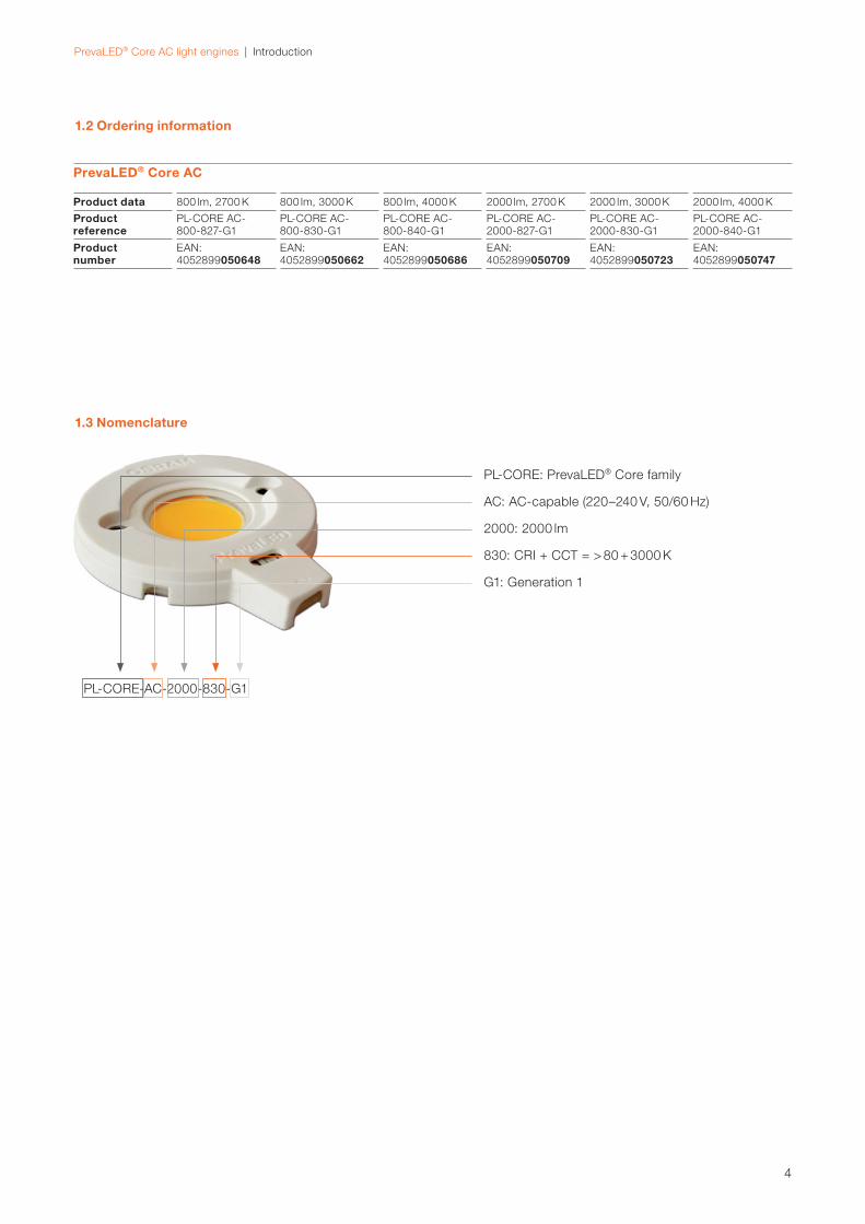
1.3 Nomenclature
PL-CORE-AC-2000-830-G1
PL-CORE: PrevaLED® Core family
AC: AC-capable (220–240 V, 50/60 Hz)
G1: Generation 1
2000: 2000 lm
830: CRI + CCT = > 80 + 3000 K
PrevaLED® Core AC
Product data 800 lm, 2700 K 800 lm, 3000 K 800 lm, 4000 K 2000 lm, 2700 K 2000 lm, 3000 K 2000 lm, 4000 K
Product reference
PL-CORE AC-800-827-G1
PL-CORE AC-800-830-G1
PL-CORE AC-800-840-G1
PL-CORE AC-2000-827-G1
PL-CORE AC-2000-830-G1
PL-CORE AC-2000-840-G1
Product number
EAN: 4052899050648
EAN: 4052899050662
EAN: 4052899050686
EAN: 4052899050709
EAN: 4052899050723
EAN: 4052899050747
5
PrevaLED® Core AC light engines | Optical considerations
2 Optical considerations
The PrevaLED® Core AC can be applied in spotlights and
downlights.
2.1 Modulation of lightDue to the limited geometry of the PrevaLED® Core AC,
there is no capacitance placed in the light engine. The
result is a light modulation which has a frequency of
100 Hz. The light output goes down to 0 %.
Warning: This light modulation might infl uence the percep-
tion of moving or rotating parts. Do not use the light engine
in critical applications such as turnery. The light engine
might also cause interference with monochrome LCDs
(twisted nematic displays).
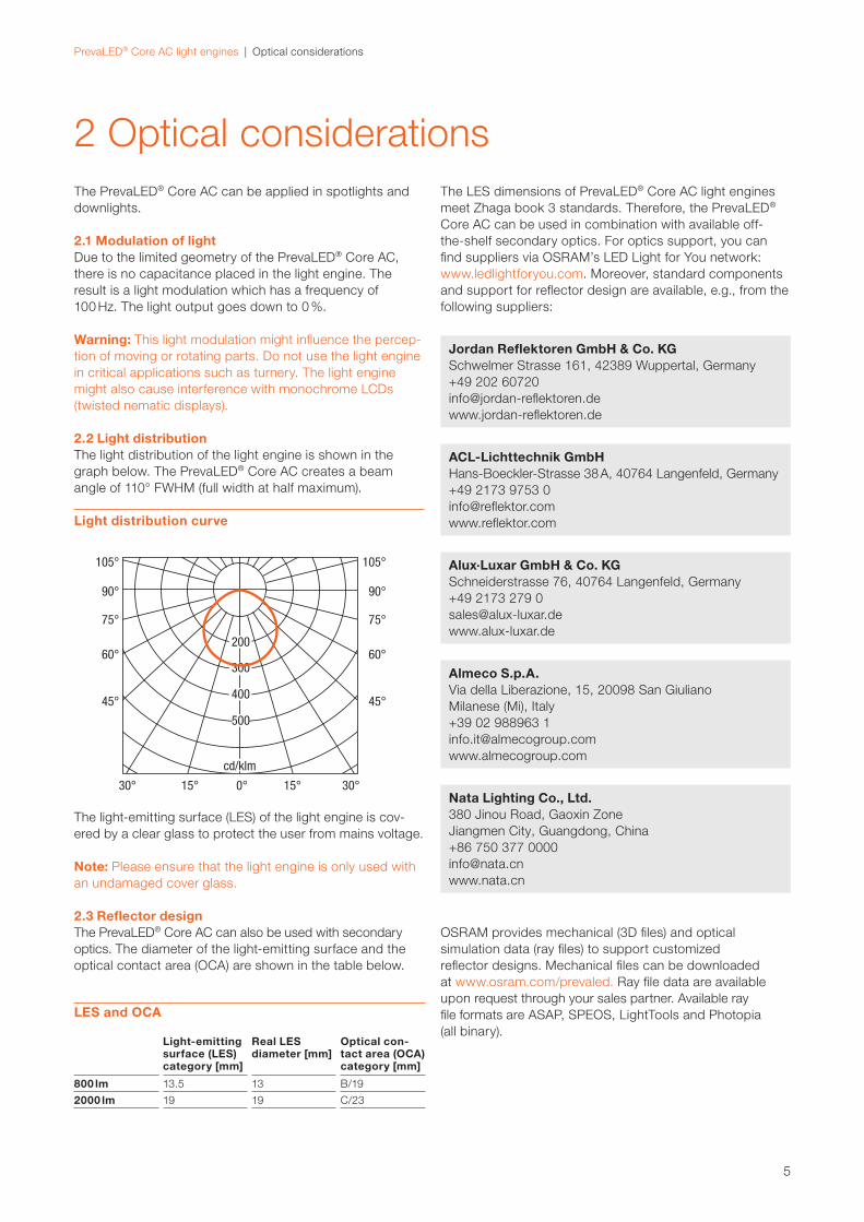
2.2 Light distributionThe light distribution of the light engine is shown in the
graph below. The PrevaLED® Core AC creates a beam
angle of 110° FWHM (full width at half maximum).
The light-emitting surface (LES) of the light engine is cov-
ered by a clear glass to protect the user from mains voltage.
Note: Please ensure that the light engine is only used with
an undamaged cover glass.
2.3 Refl ector designThe PrevaLED® Core AC can also be used with secondary
optics. The diameter of the light-emitting surface and the
optical contact area (OCA) are shown in the table below.
The LES dimensions of PrevaLED® Core AC light engines
meet Zhaga book 3 standards. Therefore, the PrevaLED®
Core AC can be used in combination with available off-
the-shelf secondary optics. For optics support, you can
fi nd sup pliers via OSRAM’s LED Light for You network:
www.ledlightforyou.com. Moreover, standard components
and support for refl ector design are available, e.g., from the
following suppliers:
Jordan Refl ektoren GmbH & Co. KGSchwelmer Strasse 161, 42389 Wuppertal, Germany
+49 202 60720
info@jordan-refl ektoren.de
www.jordan-refl ektoren.de
ACL-Lichttechnik GmbHHans-Boeckler-Strasse 38 A, 40764 Langenfeld, Germany
+49 2173 9753 0
info@refl ektor.com
www.refl ektor.com
Alux·Luxar GmbH & Co. KGSchneiderstrasse 76, 40764 Langenfeld, Germany
+49 2173 279 0
www.alux-luxar.de
Almeco S.p.A.Via della Liberazione, 15, 20098 San Giuliano
Milanese (Mi), Italy
+39 02 988963 1
www.almecogroup.com
Nata Lighting Co., Ltd.380 Jinou Road, Gaoxin Zone
Jiangmen City, Guangdong, China
+86 750 377 0000
www.nata.cn
OSRAM provides mechanical (3D fi les) and optical
simu lation data (ray fi les) to support customized
refl ector designs. Mechanical fi les can be downloaded
at www.osram.com/prevaled. Ray fi le data are available
upon request through your sales partner. Available ray
fi le formats are ASAP, SPEOS, LightTools and Photopia
(all binary).
LES and OCA
Light-emitting surface (LES) category [mm]
Real LESdiameter [mm]
Optical con-tact area (OCA) category [mm]
800 lm 13.5 13 B/19
2000 lm 19 19 C/23
Light distribution curve
6
PrevaLED® Core AC light engines | Optical considerations
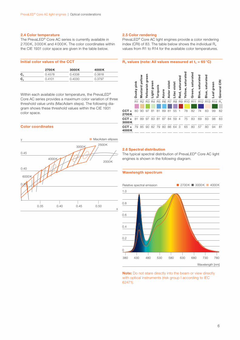
2.4 Color temperatureThe PrevaLED® Core AC series is currently available in
2 700 K, 3 000 K and 4 000 K. The color coordinates within
the CIE 1931 color space are given in the table below.
Within each available color temperature, the PrevaLED®
Core AC series provides a maximum color variation of three
threshold value units (MacAdam steps). The following dia-
gram shows these threshold values within the CIE 1931
color space.
2.5 Color renderingPrevaLED® Core AC light engines provide a color rendering
index (CRI) of 83. The table below shows the individual Ra
values from R1 to R14 for the available color temperatures.
2.6 Spectral distributionThe typical spectral distribution of PrevaLED® Core AC light
engines is shown in the following diagram.
Note: Do not stare directly into the beam or view directly
with optical instruments (risk group I according to IEC
62471).
Initial color values of the CCT
2700 K 3000 K 4000 K
Cx 0.4578 0.4338 0.3818
Cy 0.4101 0.4030 0.3797
Ra values (note: All values measured at tc = 65 °C)
Du
sky
pin
k
Mu
sta
rd y
ell
ow
Ye
llow
ish
gre
en
Lig
ht
gre
en
Turq
uo
is
Azu
re
Ast
er
vio
let
Lila
c vi
ole
t
Re
d, s
atu
rate
d
Ye
llow
, sa
tura
ted
Gre
en
, sa
tura
ted
Blu
e, s
atu
rate
d
Blu
e, s
atu
rate
d
Le
af
gre
en
Ge
ne
ral C
RI
R1 R2 R3 R4 R5 R6 R7 R8 R9 R10 R11 R12 R13 R14 Ra
CCT = 2700 K
80 90 97 81 81 89 81 55 1 78 82 74 83 99 82
CCT = 3000 K
81 89 97 83 81 87 84 59 4 75 83 69 83 98 83
CCT =4000 K
79 85 90 82 79 80 86 64 3 65 80 57 80 94 81Color coordinates
Wavelength spectrum
MacAdam ellipses
0.40
0.45
0.35 0.40 0.45 0.50
3000 K
6000 K
2500 K
2000 K4000 K
y
x
2700 K 3000 K 4000 K
1.0
0.8
0.6
0.4
0.2
0
Relative spectral emission
380 430 480 530 580 630 680 730 780
Wavelength [nm]
0.35
7
PrevaLED® Core AC light engines | Ingress protection | Electrical considerations
3 Ingress protection
4 Electrical considerations
The PrevaLED® Core AC has an ingress protection rating of
IP20. Please ensure that the housing of your luminaire pro-
vides the IP protection required for your application.
For further information, please have a look at the technical
application guide “IP codes in accordance with IEC 60529”,
which can be downloaded from www.osram.com.
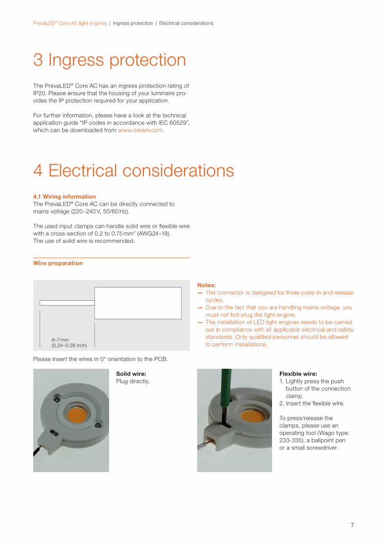
4.1 Wiring informationThe PrevaLED® Core AC can be directly connected to
mains voltage (220–240 V, 50/60 Hz).
The used input clamps can handle solid wire or fl exible wire
with a cross-section of 0.2 to 0.75 mm2 (AWG24–18).
The use of solid wire is recommended.
Notes: — The connector is designed for three poke-in and release
cycles.
— Due to the fact that you are handling mains voltage, you
must not hot-plug the light engine.
— The installation of LED light engines needs to be carried
out in compliance with all applicable electrical and safety
standards. Only qualifi ed personnel should be allowed
to perform installations.
Please insert the wires in 0° orientation to the PCB.
Solid wire: Plug directly.
Flexible wire:1. Lightly press the push
button of the connection
clamp.
2. Insert the fl exible wire.
To press/release the
clamps, please use an
operating tool (Wago type:
233-335), a ballpoint pen
or a small screwdriver.
6–7 mm(0.24–0.28 inch)
Wire preparation
8
PrevaLED® Core AC light engines | Electrical considerations
4.2 Insulation requirements The PrevaLED® Core AC can be used in class I luminaires
without further action. The creepage distance and clear-
ance are fulfi lled. The protective cover glass is tested
according to a spring hammer test and provides class I
insulation. It prevents the user from touching the light-emit-
ting surface which is connected directly to 220–240 VAC.
The PrevaLED® Core AC has basic insulation. In class II
luminaires, additional care needs to be taken in the area
of the input connector, the metal core PCB and the metal
bushings. Between connection wires with basic insulation
and touchable metal parts or the heat sink, a second insu-
lation layer is required. The light engine must be mounted
in an electrically insulated way. You can, for example, use
an electrically insulating thermal foil which must overlap the
PrevaLED® Core AC light engine by at least 2.5 mm in all
directions. To mount the light engine, you must use non-
conductive screws or attach the light engine by a clamping
mechanism. Please note that force must be applied to
the metal bushings only.
4.3 Inrush current and system installationDue to its electronic construction, the PrevaLED® Core AC
has a minimum inrush current. In system installations, the
number of light engines which can be attached to one
circuit is limited by the voltage drop regulations and the
used diameter of the connecting wire.
4.4 Electrostatic discharge (ESD)It is not necessary to handle the PrevaLED® Core AC in
electrostatic protected areas (EPAs).
To protect the light engine from electrostatic damage, the
module must not be opened. The light engine fulfi lls the
requirement of the immunity standard IEC/EN 61547.
4.5 ControllabilityDue to the integrated drive electronics, a good compati-
bility with all available phase-cut dimmers cannot be en-
sured.
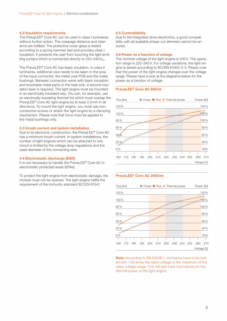
4.6 Power as a function of voltageThe nominal voltage of the light engine is 230 V. The opera-
tion range is 220–240 V. For voltage variations, the light en-
gine is tested according to IEC/EN 61000-3-3. Please note
that the power of the light engine changes over the voltage
range. Please have a look at the diagrams below for the
power as a function of voltage.
Note: According to EN 60598-1, luminaires have to be test-
ed with 1.06 times the rated voltage or the maximum of the
rated voltage range. This will also have implications on the
thermal power of the light engine.
PrevaLED® Core AC 800 lm
PrevaLED® Core AC 2000 lm
Voltage [V]
Flux [lm] Power [W]
Power Flux Thermal power
120 % 140 %
100 % 120 %
80 % 100 %
60 % 80 %
40 % 60 %
20 % 40 %
0 %
160
160
170
170
180
180
190
190
200
200
210
210
220
220
230
230
240
240
250
250
260
260
270
270
20%
Voltage [V]
Flux [lm] Power [W]
Power Flux Thermal power
120 % 140 %
100 % 120 %
80 % 100 %
60 % 80 %
40 % 60 %
20 % 40 %
0 % 20%

9
PrevaLED® Core AC light engines | Thermal considerations
5 Thermal considerations
The proper thermal design of an LED luminaire is critical
for achieving the best performance and ensuring the lon-
gest lifetime of all components. Due to the high effi cacy
of the PrevaLED® Core AC, only a partial amount of the
introduced electrical power has to be dissipated through
the back of the light engine. The thermal power that has
to be dissipated for PrevaLED® Core AC is given below.
5.1 Thermal power over voltagePlease note that the thermal power of the module is re lated
to the line voltage. Please refer to the diagrams in chapter
4.6.
5.2 Thermal shutdownTo ensure the best performance and a long lifetime of all
components, the PrevaLED® Core AC features integrated
electronics which switch off the light engine when the tem-
perature at the tc point reaches the critical value of 83 °C
(±5 °C). The light engine switches back on as soon as the
temperature has cooled down below 60 °C (±5 °C).
5.3 Thermal interface material and other accessoriesWhen mounting a PrevaLED® Core AC within a luminaire,
it is highly recommended to use thermal interface material
(TIM) between the back of the light engine and the lumi-
naire housing or heat sink. It is recommended to use
thermal paste, but thermal foil can also be used. In order
to balance possible unevenness, the material should be
applied as thinly as possible, but as thickly as necessary.
In this way, air inclusions, which may otherwise occur,
are replaced by TIM and the required heat conduction
between the back of the light engine and the contact
surfaces of the luminaire housing is achieved. For this
purpose, the planarity and smoothness of the surface
should be optimized.
The list below is a selection of suppliers of thermal interface
materials. Additional partners for thermal management
support can also be found via OSRAM’s LED Light for You
network: www.ledlightforyou.com.
5.4 Cooling systems and heat sinksFor the selection of a suitable heat sink, several points
regarding thermal resistance have to be considered.
The selection is usually done through the following
necessary steps:
Defi ne boundaryconditions
Estimate heat sinkthermal resistance on
light engine level
Select heat sinkthermal resistance
Total power dissipation of the light engine, max. ambient temperature ta, max. reference temperature tr according tolifetime requirements
Use the estimated Rth as a target for a possible heat sink profi le and examine the perfor-mance curve in the heat sink manufacturer’s catalog.
Rth =tr - ta
Pth
tr measured at the tc point
Selection of a heat sink
Note: A thermal design must always be confi rmed by per-
forming a thermal measurement in steady-state condition.
It is recommended that the whole area of the PCB of a
PrevaLED® Core AC light engine is in contact with the solid
material of the heat sink.
Note: The positioning of the mounting holes is compatible
with Zhaga book 3. Therefore, off-the-shelf heat sinks de-
veloped for these modules are also suitable for PrevaLED®
Core AC light engines.
Thermal power to be dissipated *
Typical Maximum
PL-CORE AC-800-827-G1 10.9 W 13.1 W
PL-CORE AC-800-830-G1 10.2 W 12.8 W
PL-CORE AC-800-840-G1 10.0 W 11.6 W
PL-CORE AC-2000-827-G1 21.7 W 22.6 W
PL-CORE AC-2000-830-G1 20.7 W 22.0 W
PL-CORE AC-2000-840-G1 20.2 W 20.2 W
Thermal interface materials
Alfatec www.alfatec.de
Kerafol www.kerafol.de
Laird www.lairdtech.com
Bergquist www.bergquistcompany.com
Arctic Silver www.arcticsilver.com
Wakefi eld www.wakefi eld.com
* Values measured at the tc point, at a reference temperature (tr) of 65 °C
10
PrevaLED® Core AC light engines | Thermal considerations
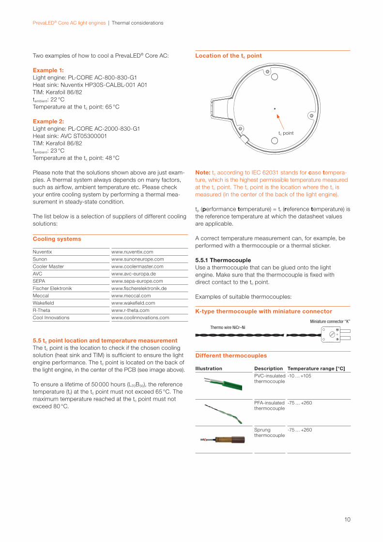
Two examples of how to cool a PrevaLED® Core AC:
Example 1: Light engine: PL-CORE AC-800-830-G1
Heat sink: Nuventix HP30S-CALBL-001 A01
TIM: Kerafoil 86/82
tambient: 22 °C
Temperature at the tc point: 65 °C
Example 2: Light engine: PL-CORE AC-2000-830-G1
Heat sink: AVC ST05300001
TIM: Kerafoil 86/82
tambient: 23 °C
Temperature at the tc point: 48 °C
Please note that the solutions shown above are just exam-
ples. A thermal system always depends on many factors,
such as airfl ow, ambient temperature etc. Please check
your entire cooling system by performing a thermal mea-
surement in steady-state condition.
The list below is a selection of suppliers of different cooling
solutions:
5.5 tc point location and temperature measurementThe tc point is the location to check if the chosen cooling
solution (heat sink and TIM) is suffi cient to ensure the light
engine performance. The tc point is located on the back of
the light engine, in the center of the PCB (see image above).
To ensure a lifetime of 50 000 hours (L70B30), the reference
temperature (tr) at the tc point must not exceed 65 °C. The
maximum temperature reached at the tc point must not
exceed 80 °C.
tc point
5.5.1 ThermocoupleUse a thermocouple that can be glued onto the light
engine. Make sure that the thermocouple is fi xed with
direct contact to the tc point.
Examples of suitable thermocouples:
Note: tc according to IEC 62031 stands for case tempera-
ture, which is the highest permissible temperature measured
at the tc point. The tc point is the location where the tc is
measured (in the center of the back of the light engine).
tp (performance temperature) = tr (reference temperature) is
the reference temperature at which the datasheet values
are applicable.
A correct temperature measurement can, for example, be
performed with a thermocouple or a thermal sticker.Cooling systems
Nuventix www.nuventix.com
Sunon www.sunoneurope.com
Cooler Master www.coolermaster.com
AVC www.avc-europa.de
SEPA www.sepa-europe.com
Fischer Elektronik www.fi scherelektronik.de
Meccal www.meccal.com
Wakefi eld www.wakefi eld.com
R-Theta www.r-theta.com
Cool Innovations www.coolinnovations.com
Different thermocouples
Illustration Description Temperature range [°C]
PVC-insulated thermo couple
-10 … +105
PFA-insulated thermo couple
-75 … +260
Sprung thermo couple
-75 … +260
Location of the tc point
K-type thermocouple with miniature connector
11
PrevaLED® Core AC light engines | Thermal considerations
Note: If you use a TIM, please do not apply thermal paste
to the sticker. In case you use thermal foil, please cut out
the area of the sticker.
Mount the light engine onto the heat sink and operate it
until a stable temperature has been reached. Dismount
the light engine and check the thermal sticker. For the
interpretation of the test result, refer to the datasheet of
the thermal sticker.
OMEGA BUA2-140/60-30 is a suitable thermal sticker,
which covers a temperature range between 60 and 77 °C.
5.5.3 Thermal dummyOn request, a Zhaga-specifi ed thermal test dummy for
design-in tasks is available from your sales partner.
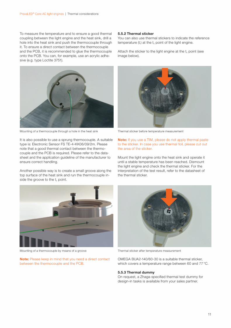
Thermal sticker before temperature measurement
Thermal sticker after temperature measurement
5.5.2 Thermal stickerYou can also use thermal stickers to indicate the reference
temperature (tr) at the tc point of the light engine.
Attach the sticker to the light engine at the tc point (see
image below).
Note: Please keep in mind that you need a direct contact
between the thermocouple and the PCB.
It is also possible to use a sprung thermocouple. A suitable
type is: Electronic Sensor FS TE-4-KK06/09/2m. Please
note that a good thermal contact between the thermo-
couple and the PCB is required. Please refer to the data-
sheet and the application guideline of the manufacturer to
ensure correct handling.
Another possible way is to create a small groove along the
top surface of the heat sink and run the thermocouple in-
side the groove to the tc point.
Mounting of a thermocouple by means of a groove
To measure the temperature and to ensure a good thermal
coupling between the light engine and the heat sink, drill a
hole into the heat sink and push the thermocouple through
it. To ensure a direct contact between the thermo couple
and the PCB, it is recommended to glue the thermocouple
onto the PCB. You can, for example, use an acrylic adhe-
sive (e.g. type Loctite 3751).
Mounting of a thermocouple through a hole in the heat sink
12
PrevaLED® Core AC light engines | Lifetime and thermal behavior
6 Lifetime and thermal behavior
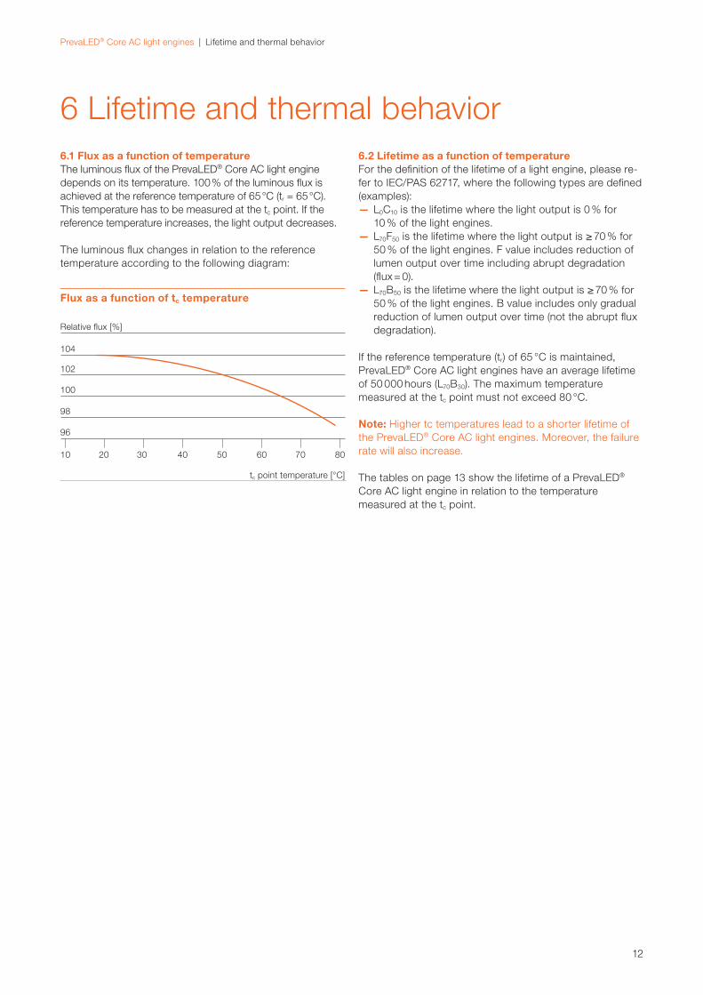
6.1 Flux as a function of temperatureThe luminous fl ux of the PrevaLED® Core AC light engine
depends on its temperature. 100 % of the luminous fl ux is
achieved at the reference temperature of 65 °C (tr = 65 °C).
This temperature has to be measured at the tc point. If the
reference temperature increases, the light output decreases.
The luminous fl ux changes in relation to the reference
temperature according to the following diagram:
6.2 Lifetime as a function of temperatureFor the defi nition of the lifetime of a light engine, please re-
fer to IEC/PAS 62717, where the following types are defi ned
(examples):
— L0C10 is the lifetime where the light output is 0 % for
10 % of the light engines.
— L70F50 is the lifetime where the light output is ≥ 70 % for
50 % of the light engines. F value includes reduction of
lumen output over time including abrupt degradation
(fl ux = 0).
— L70B50 is the lifetime where the light output is ≥ 70 % for
50 % of the light engines. B value includes only gradual
reduction of lumen output over time (not the abrupt fl ux
degradation).
If the reference temperature (tr) of 65 °C is maintained,
PrevaLED® Core AC light engines have an average lifetime
of 50 000 hours (L70B30). The maximum temperature
measured at the tc point must not exceed 80 °C.
Note: Higher tc temperatures lead to a shorter lifetime of
the PrevaLED® Core AC light engines. Moreover, the failure
rate will also increase.
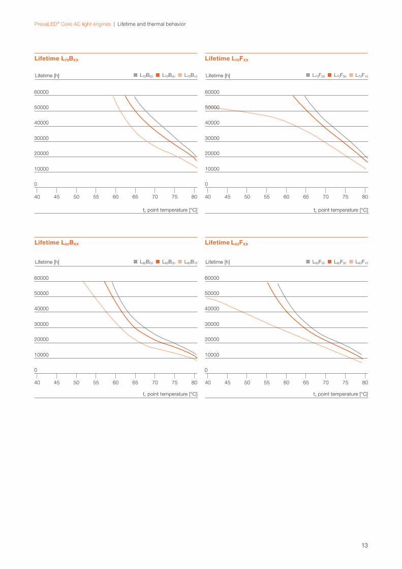
The tables on page 13 show the lifetime of a PrevaLED®
Core AC light engine in relation to the temperature
measured at the tc point.
Flux as a function of tc temperature
tc point temperature [°C]
96
98
100
102
104
Relative fl ux [%]
8070605040302010
13
PrevaLED® Core AC light engines | Lifetime and thermal behavior
tc point temperature [°C]
Lifetime [h]
60000
50000
40000
30000
20000
10000
0
40
40
45
45
50
50
55
55
60
60
65
65
70
70
75
75
80
80
L70B50 L70B30 L70B10
L70F50 L70F30 L70F10
Lifetime L70BXX
Lifetime L80BXX Lifetime L80FXX
Lifetime L70FXX
tc point temperature [°C]
Lifetime [h]
60000
50000
40000
30000
20000
10000
0
40
40
45
45
50
50
55
55
60
60
65
65
70
70
75
75
80
80
tc point temperature [°C] tc point temperature [°C]
Lifetime [h] Lifetime [h]
60000 60000
50000 50000
40000 40000
30000 30000
20000 20000
10000 10000
0 0
L80B50 L80B30 L80B10
L80F50 L80F30 L80F10

14
PrevaLED® Core AC light engines | Mechanical considerations
7 Mechanical considerations
7.1 Outline drawingThe following schematic drawing provides further details
on the dimensions of PrevaLED® Core AC light engines.
For 3D fi les of the light engines, please go to:
www.osram.com.
7.3 Mechanical protection of the light engineNote: The housing of a PrevaLED® Core AC light engine
must not be exposed to strong mechanical stress. Please
apply force only to the dedicated mounting positions.
Strong mechanical stress can lead to irreversible damage
of the light engine.
Note: If the protection glass at the light-emitting surface or
any other part of the housing or the PCB is broken or me-
chanically damaged, you must no longer operate the light
engine. Please replace it immediately to avoid contact with
parts of the light engine that conduct 230 V!
For operation in damp, wet or dusty environments, the user
has to make sure that an adequate ingress protection is
chosen. The light engine has to be protected by a suitable
IP classifi cation of the luminaire housing. Please consider
the luminaire standard IEC 60598-1 as well as the different
requirements.
7.4 Mounting To fi x a PrevaLED® Core AC light engine to a heat sink, you
can use M3 cylinder-head screws according to DIN 7984. If
you cannot use DIN screws, please use the following speci-
fi cation: height of head not more than 2.6 mm, diameter of
head below 5.5 mm. The allowed torque is 0.4 to 0.6 Nm.
kg
1. Don’t connect the module when the glass cover is broken.
2. Do not mechanically stress the module.
3. The LED light engine has to be built into a luminaire.
Mount the light engine from the top
All fi gures in mm
7.2 3D drawing
Move me!
Movable 3D PrevaLED® Core AC light engine
(works with Adobe Acrobat 7 or higher)
Technical drawing
15
PrevaLED® Core AC light engines | Assembly in a reference luminaire
8 Assembly in a reference luminaire
To show you how easy it is to equip a luminaire with a
PrevaLED® Core AC, the following example guides you
through all necessary steps. In this case, the luminaire
housing is used as the heat sink.
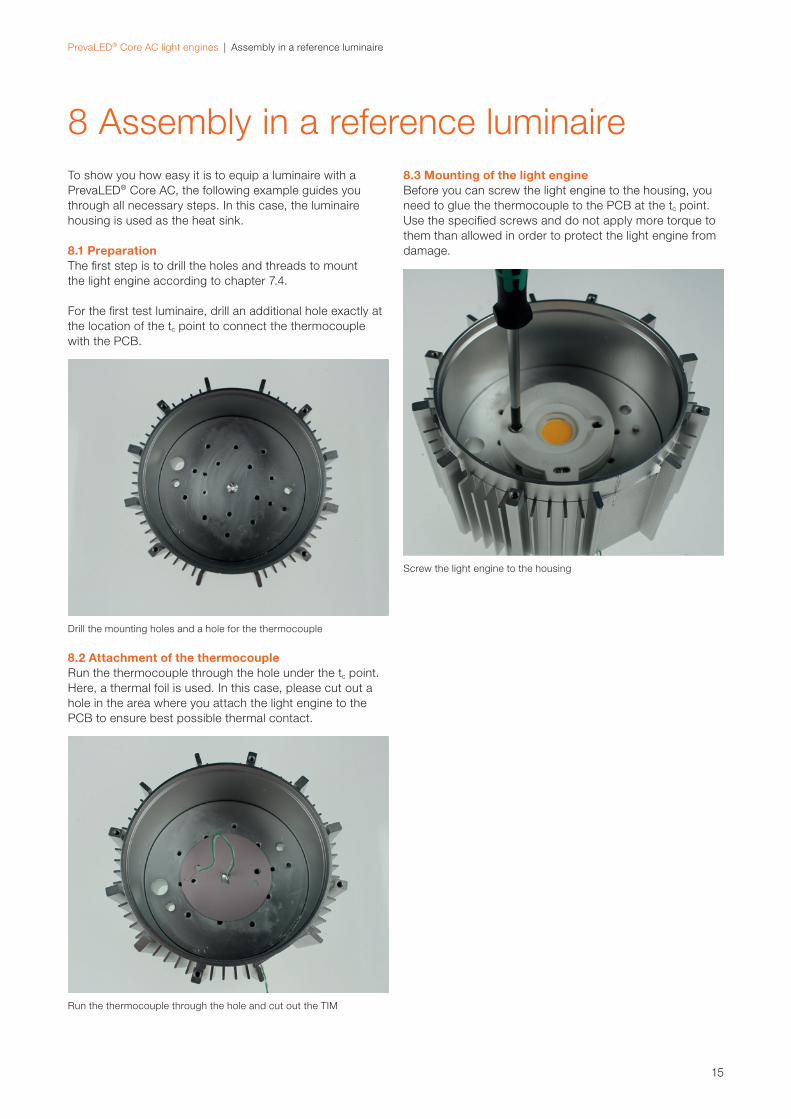
8.1 PreparationThe fi rst step is to drill the holes and threads to mount
the light engine according to chapter 7.4.
For the fi rst test luminaire, drill an additional hole exactly at
the location of the tc point to connect the thermocouple
with the PCB.
8.2 Attachment of the thermocoupleRun the thermocouple through the hole under the tc point.
Here, a thermal foil is used. In this case, please cut out a
hole in the area where you attach the light engine to the
PCB to ensure best possible thermal contact.
8.3 Mounting of the light engineBefore you can screw the light engine to the housing, you
need to glue the thermocouple to the PCB at the tc point.
Use the specifi ed screws and do not apply more torque to
them than allowed in order to protect the light engine from
damage.
Drill the mounting holes and a hole for the thermocouple
Screw the light engine to the housing
Run the thermocouple through the hole and cut out the TIM
16
PrevaLED® Core AC light engines | Assembly in a reference luminaire
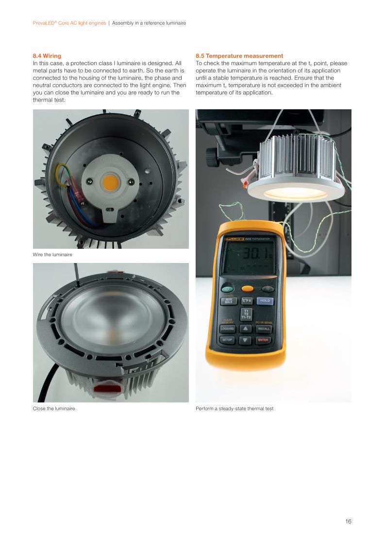
8.4 WiringIn this case, a protection class I luminaire is designed. All
metal parts have to be connected to earth. So the earth is
connected to the housing of the luminaire, the phase and
neutral conductors are connected to the light engine. Then
you can close the luminaire and you are ready to run the
thermal test.
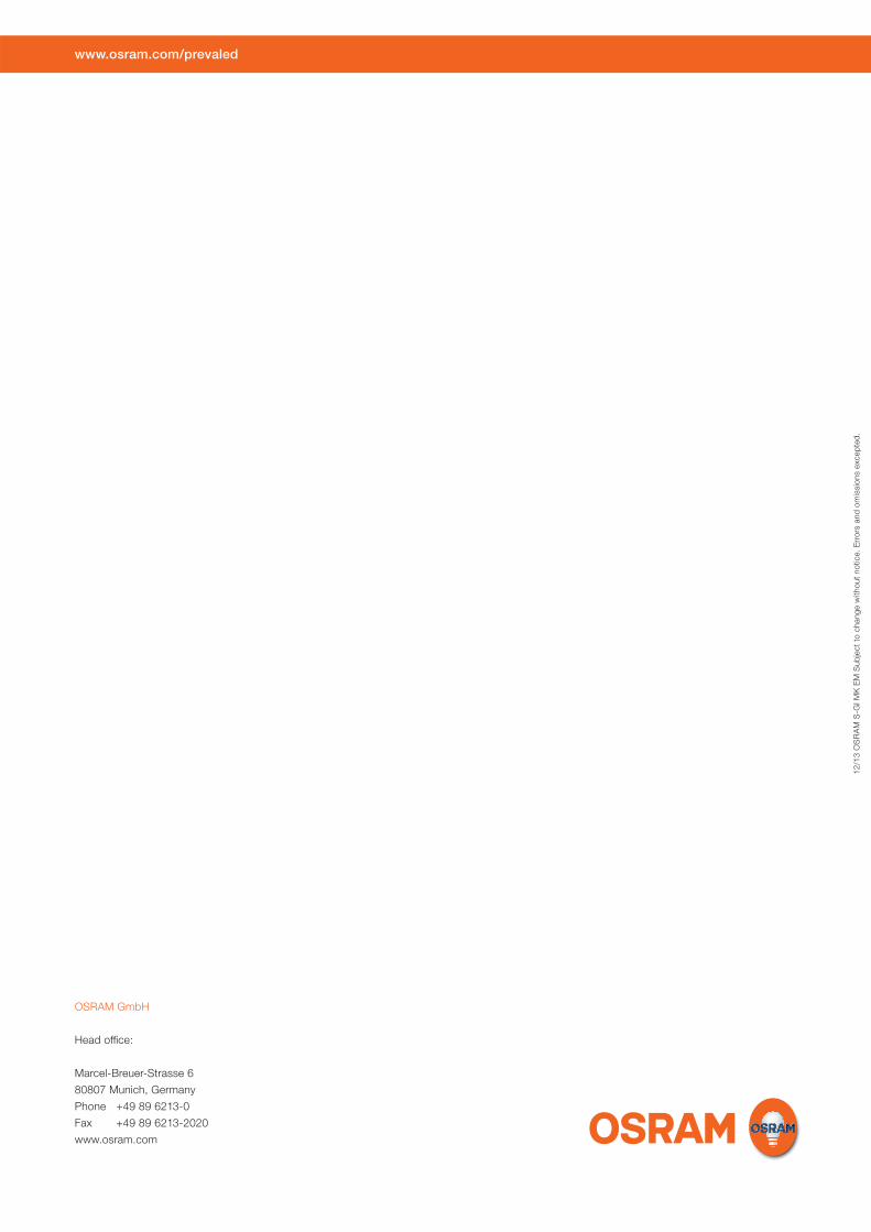
8.5 Temperature measurementTo check the maximum temperature at the tc point, please
operate the luminaire in the orientation of its application
until a stable temperature is reached. Ensure that the
maximum tc temperature is not exceeded in the ambient
temperature of its application.
Wire the luminaire
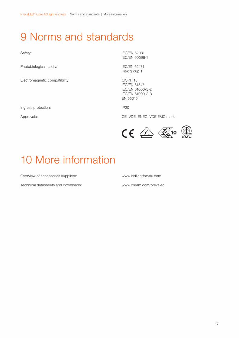
Close the luminaire Perform a steady-state thermal test
17
PrevaLED® Core AC light engines | Norms and standards | More information
Safety: IEC/EN 62031
IEC/EN 60598-1
Photobiological safety: IEC/EN 62471
Risk group 1
Electromagnetic compatibility: CISPR 15
IEC/EN 61547
IEC/EN 61000-3-2
IEC/EN 61000-3-3
EN 55015
Ingress protection: IP20
Approvals: CE, VDE, ENEC, VDE EMC mark
9 Norms and standards
10
Overview of accessories suppliers: www.ledlightforyou.com
Technical datasheets and downloads: www.osram.com/prevaled
10 More information
www.osram.com/prevaled
OSRAM GmbH
Head offi ce:
Marcel-Breuer-Strasse 6
80807 Munich, Germany
Phone +49 89 6213-0
Fax +49 89 6213-2020
www.osram.com
12
/13
OS
RA
M S
-GI M
K E
M S
ub
ject
to c
han
ge w
ith
ou
t n
otice.
Err
ors
an
d o
mis
sio
ns e
xcep
ted
.


