50
Project Planning DOK-MOTOR*-2AD280*****-PR01-AE-P 2AD280 Main Spindle Motor 2 8 3 3 6 5
Project Planning
DOK-MOTOR*-2AD280*****-PR01-AE-P
2AD280 Main Spindle Motor
2 8 3 3 6 5

About this document 2AD280 Spindle Motor
DOK-MOTOR*-2AD280*****-PR01-AE-P • 03/99
2AD280 Main Spindle Motor
Project Planning
DOK-MOTOR*-2AD280*****-PR01-AE-P
Publication Number
120-1500-B301-01/AE
This document
• introduces the 2AD280 spindle motor,
• specifies technical information about the structural features of the2AD280 spindle motor,
• assists in selecting the main spindle motor relevant to your needs andapplications, and,
• outlines the technical data for the 2AD280 main spindle motor.
Revision Date Remarks
01 03/99 Initial Release
INDRAMAT GmbH, 1998
Copying this document, and giving it to others and the use or communicationof the contents thereof without express authority, are forbidden. Offenders areliable for the payment of damages. All rights are reserved in the event of thegrant of a patent or the registration of a utility model or design (DIN 34-1).
All rights are reserved with respect to the content of this documentation andthe availability of the product.
Mannesmann Rexroth • Indramat Division
5150 Prairie Stone Parkway • Hoffman Estates, Illinois • 60192
Phone (847) 645-3600 • Fax (847) 645-6201
TechDoc ..... (DP)
Title
Documentation Type
Document Typecode
Internal File Reference
Purpose of Document
Record of Revisions
Copy right
Validity
Published by

2AD280 Spindle Motor Contents I
DOK-MOTOR*-2AD280*****-PR01-AE-P • 03/99
Contents
1 2AD280 Main Spindle Motor 1-1
2 Mechanical integration into the machine 2-12.1 Environmental conditions ........................................................................................................................... 2-1
2.2 Mechanical Features.................................................................................................................................. 2-4
2.3 Electrical features....................................................................................................................................... 2-7
3 Technical Data - 2AD280 3-13.1 Main spindle motor..................................................................................................................................... 3-1
Motor / Drive Combination................................................................................................................... 3-2
2AD280A-… / DKR5.1-W400-… Speed torque curves....................................................................... 3-3
2AD280B-… / DKR5.1-W600-… Speed torque curves....................................................................... 3-4
2AD280C-… / DKR5.1-W800-… Speed torque curves ...................................................................... 3-5
Permissible shaft loading 2AD280 A/B................................................................................................ 3-6
Permissible shaft loading 2AD280 C................................................................................................... 3-7
3.2 Motor blower .............................................................................................................................................. 3-8
3.3 Typecode ................................................................................................................................................. 3-11
4 Condition at delivery 4-14.1 General Information ................................................................................................................................... 4-1
4.2 Shipping papers ......................................................................................................................................... 4-1
5 Identifying the merchandise 5-15.1 Delivery slip ................................................................................................................................................ 5-1
5.2 Barcode sticker .......................................................................................................................................... 5-1
5.3 Name plate................................................................................................................................................. 5-1
6 Storage, Transport and Handling 6-16.1 Notes on the package ................................................................................................................................ 6-1
6.2 Storage....................................................................................................................................................... 6-1
6.3 Transport and handling .............................................................................................................................. 6-1
7 Safety guidelines for electrical drives 7-17.1 General information.................................................................................................................................... 7-1
7.2 Notes on Protection against contact with electrical parts........................................................................... 7-2

II Contents 2AD280 Spindle Motor
DOK-MOTOR*-2AD280*****-PR01-AE-P • 03/99
7.3 Notes on protecting "safely-isolated low voltages"..................................................................................... 7-3
7.4 Note on handling and mounting ................................................................................................................. 7-3
7.5 Guidelines on protection against dangerous movements .......................................................................... 7-3
8 Mounting and installation guidelines 8-1
9 Service Notes 9-19.1 Maintenance work ...................................................................................................................................... 9-1
9.2 Contacting Customer Service .................................................................................................................... 9-1
10 Commissioning 10-1
11 Index 11-1
2AD280 Spindle Motor 2AD280 Main Spindle Motor 1-1
DOK-MOTOR*-2AD280*****-PR01-AE-P • 03/99
1 2AD280 Main Spindle Motor2AD Main spindle motors are used with the DKR5 Vector drive in suchapplications as,
• Printing machines
• Converting machine
• Test stands
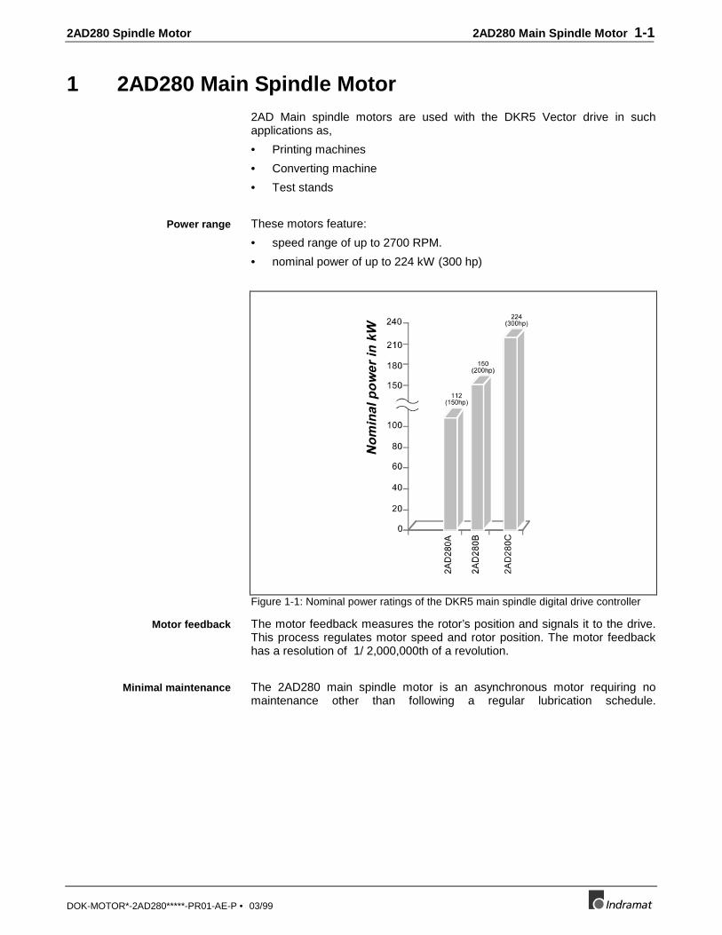
These motors feature:
• speed range of up to 2700 RPM.
• nominal power of up to 224 kW (300 hp)
Figure 1-1: Nominal power ratings of the DKR5 main spindle digital drive controller
The motor feedback measures the rotor’s position and signals it to the drive.This process regulates motor speed and rotor position. The motor feedbackhas a resolution of 1/ 2,000,000th of a revolution.
The 2AD280 main spindle motor is an asynchronous motor requiring nomaintenance other than following a regular lubrication schedule.
Power range
Motor feedback
Minimal maintenance

1-2 2AD280 Main Spindle Motor 2AD280 Spindle Motor
DOK-MOTOR*-2AD280*****-PR01-AE-P • 03/99

2AD280 Spindle Motor Mechanical integration into the machine 2-1
DOK-MOTOR*-2AD280*****-PR01-AE-P • 03/99
2 Mechanical integration into the machine
2.1 Environmental conditions
The ratings outlined in this document are achieved under the followingconditions:
• ambient temperatures of 0 °C (32 °F) to +40 °C (104 °F)
• installation altitudes of 0 to 1,000 meters (3,280 feet) above sea level
If the motors are to be used above this range, then the "Load capacityfactors" must be taken into account. This de-rates the power data.
⇒ In cases like this, check to see if whether the power data still satisfies yourapplication. To determine the load capacity factor, please check Figure 2-1. Values exceeding those depicted in the illustration for temperature orinstallation elevations are not recommended!
Figure 2-1: Load capacities based on ambient temperatures and installation altitudes
If either the ambient temperature or the installation elevation exceed therated data:
⇒ Multiply the continuous torque at standstill data found in the selection listswith the load capacity factor which was determined.
⇒ Make sure that the de-rated torque data are not exceeded by yourapplication.
If both ambient temperature and installation elevation exceed rated data:
⇒ Multiply the determined load capacity factors fT and fH.⇒ Multiply the determined value with the continuous torque data at standstill
listed in the selection lists of the motor.Ascertain that de-rated torque data are not exceeded by the application.
Installation requirements:ambient temperature and
altitude
2-2 Mechanical integration into the machine 2AD280 Spindle Motor
DOK-MOTOR*-2AD280*****-PR01-AE-P • 03/99
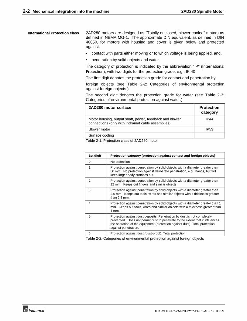
2AD280 motors are designed as "Totally enclosed, blower cooled" motors asdefined in NEMA MG-1. The approximate DIN equivalent, as defined in DIN40050, for motors with housing and cover is given below and protectedagainst:
• contact with parts either moving or to which voltage is being applied, and,
• penetration by solid objects and water.
The category of protection is indicated by the abbreviation "IP" (InternationalProtection), with two digits for the protection grade, e.g., IP 40
The first digit denotes the protection grade for contact and penetration by
foreign objects (see Table 2-2: Categories of environmental protectionagainst foreign objects.)
The second digit denotes the protection grade for water (see Table 2-3:Categories of environmental protection against water.)
2AD280 motor surface Protectioncategory
Motor housing, output shaft, power, feedback and blowerconnections (only with Indramat cable assemblies)
IP44
Blower motor IP53
Surface coolingTable 2-1: Protection class of 2AD280 motor
1st digit Protection category (protection against contact and foreign objects)
0 No protection
1 Protection against penetration by solid objects with a diameter greater than50 mm. No protection against deliberate penetration, e.g., hands, but willkeep larger body surfaces out.
2 Protection against penetration by solid objects with a diameter greater than12 mm. Keeps out fingers and similar objects.
3 Protection against penetration by solid objects with a diameter greater than2.5 mm. Keeps out tools, wires and similar objects with a thickness greaterthan 2.5 mm.
4 Protection against penetration by solid objects with a diameter greater than 1mm. Keeps out tools, wires and similar objects with a thickness greater than1 mm.
5 Protection against dust deposits. Penetration by dust is not completelyprevented. Does not permit dust to penetrate to the extent that it influencesthe operation of the equipment (protection against dust). Total protectionagainst penetration.
6 Protection against dust (dust-proof). Total protection.
Table 2-2: Categories of environmental protection against foreign objects
International Protection class
2AD280 Spindle Motor Mechanical integration into the machine 2-3
DOK-MOTOR*-2AD280*****-PR01-AE-P • 03/99
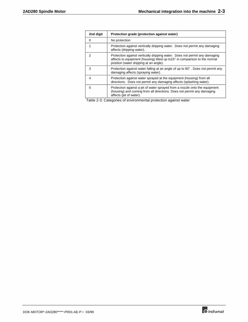
2nd digit Protection grade (protection against water)
0 No protection
1 Protection against vertically dripping water. Does not permit any damagingaffects (dripping water).
2 Protection against vertically dripping water. Does not permit any damagingaffects to equipment (housing) tilted up to15° in comparison to the normalposition (water dripping at an angle).
3 Protection against water falling at an angle of up to 60° . Does not permit anydamaging affects (spraying water).
4 Protection against water sprayed at the equipment (housing) from alldirections. Does not permit any damaging affects (splashing water).
5 Protection against a jet of water sprayed from a nozzle onto the equipment(housing) and coming from all directions. Does not permit any damagingaffects (jet of water).
Table 2-3: Categories of environmental protection against water

2-4 Mechanical integration into the machine 2AD280 Spindle Motor
DOK-MOTOR*-2AD280*****-PR01-AE-P • 03/99
2.2 Mechanical Features
The 2AD280 main spindle motor from Indramat is only available with B03,foot mount design only
Motor Installation positionsper DIN IEC 34-7
Installation guidelines
B03 Foot installation:
Do not permit the following loads on themotor feet:
Radial loads affecting the motor feet inthe form of a traction force.In this case, alter the installationposition.
Transmission of loads occurring at thedrive. If possible, mount the motor anddrive separately.
Table 2-4: Allowable installation position
Plain shaft:
For friction-locked shaft-hub connections.
The higher run quality and the backlash-free connection between shaft and
hub are a significant advantage of this recommended design.
Output shaft with key:
For a form-fitting shaft-hub connection.
• Balanced with full key:
The rotor is balanced with the key used in the shaft-hub assembly. Therotor is balanced with the full key. A balanced, interconnecting part(toothed wheel etc.) must be used. The keyway in the hub is notdependent upon the length of the key.
• Balancing with a half-key:
The rotor is balanced with a half-key in the keyway. The mass ratiosoccurring at the keyway are comparable to those of a plain shaft. If a fullkey is inserted, then the projecting section of the key creates a state ofimbalance. The rotor with the full key is not balanced.
The interconnecting part must equalize the rotor’s state of imbalance. Thekeyway in the hub should correspond to the length of the key. Use a steppedkey for shorter keyways.
Construction type andinstallation position
Output shaft
2AD280 Spindle Motor Mechanical integration into the machine 2-5
DOK-MOTOR*-2AD280*****-PR01-AE-P • 03/99
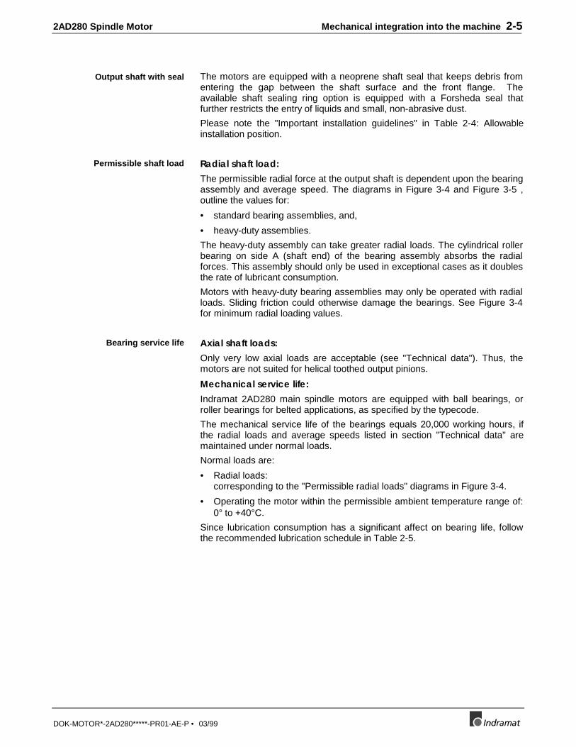
The motors are equipped with a neoprene shaft seal that keeps debris fromentering the gap between the shaft surface and the front flange. Theavailable shaft sealing ring option is equipped with a Forsheda seal thatfurther restricts the entry of liquids and small, non-abrasive dust.
Please note the "Important installation guidelines" in Table 2-4: Allowableinstallation position.
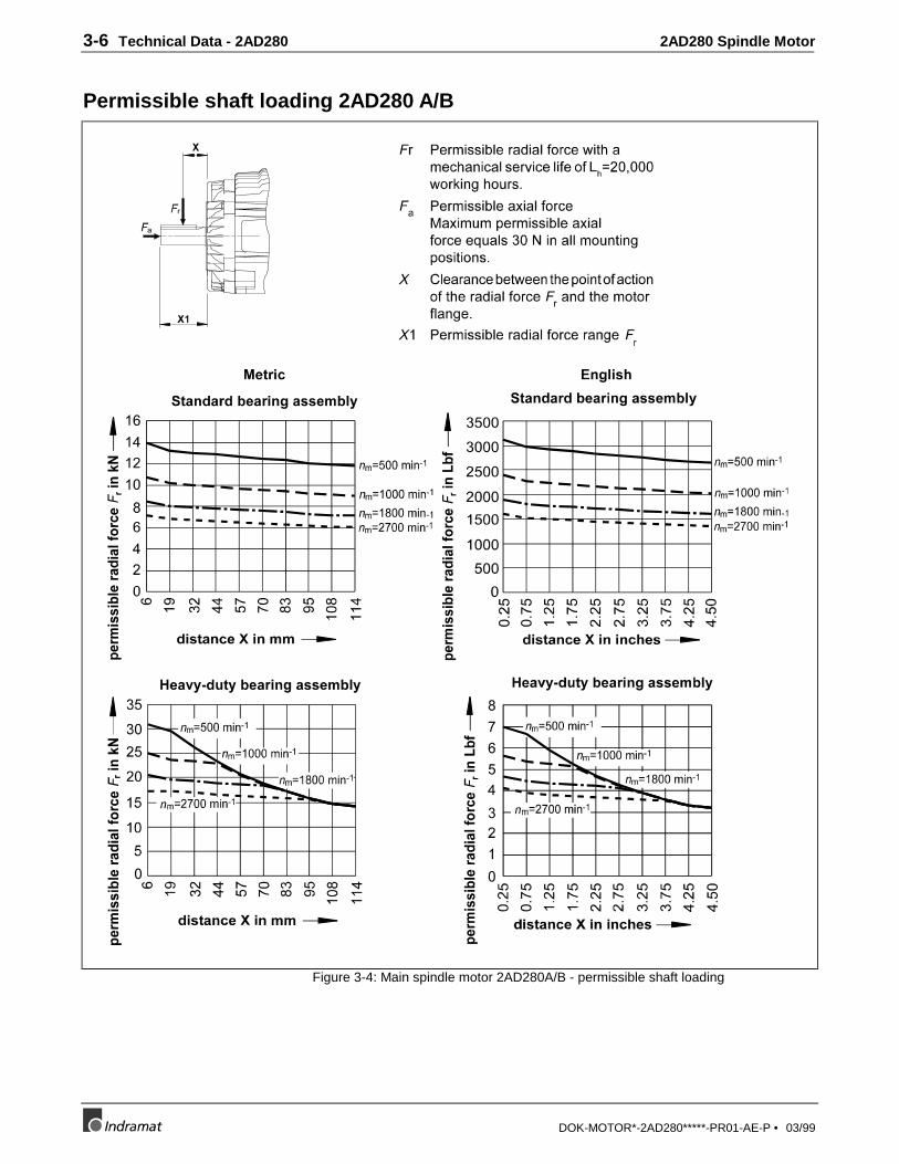
Radial shaft load:The permissible radial force at the output shaft is dependent upon the bearingassembly and average speed. The diagrams in Figure 3-4 and Figure 3-5 ,outline the values for:
• standard bearing assemblies, and,
• heavy-duty assemblies.
The heavy-duty assembly can take greater radial loads. The cylindrical rollerbearing on side A (shaft end) of the bearing assembly absorbs the radialforces. This assembly should only be used in exceptional cases as it doublesthe rate of lubricant consumption.
Motors with heavy-duty bearing assemblies may only be operated with radialloads. Sliding friction could otherwise damage the bearings. See Figure 3-4for minimum radial loading values.
Axial shaft loads:Only very low axial loads are acceptable (see "Technical data"). Thus, themotors are not suited for helical toothed output pinions.
Mechanical service life:Indramat 2AD280 main spindle motors are equipped with ball bearings, orroller bearings for belted applications, as specified by the typecode.
The mechanical service life of the bearings equals 20,000 working hours, ifthe radial loads and average speeds listed in section "Technical data" aremaintained under normal loads.
Normal loads are:
• Radial loads:corresponding to the "Permissible radial loads" diagrams in Figure 3-4.
• Operating the motor within the permissible ambient temperature range of:0° to +40°C.
Since lubrication consumption has a significant affect on bearing life, followthe recommended lubrication schedule in Table 2-5.
Output shaft with seal
Permissible shaft load
Bearing service life
2-6 Mechanical integration into the machine 2AD280 Spindle Motor
DOK-MOTOR*-2AD280*****-PR01-AE-P • 03/99
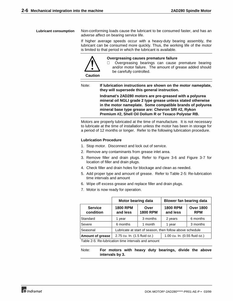
Non-conforming loads cause the lubricant to be consumed faster, and has anadverse affect on bearing service life.
If higher average speeds occur with a heavy-duty bearing assembly, thelubricant can be consumed more quickly. Thus, the working life of the motoris limited to that period in which the lubricant is available.
Caution
Overgreasing causes premature failure⇒ Overgreasing bearings can cause premature bearing
and/or motor failure. The amount of grease added shouldbe carefully controlled.
Note: If lubrication instructions are shown on the motor nameplate,they will supersede this general instruction.
Indramat’s 2AD280 motors are pre-greased with a polyureamineral oil NGLI grade 2 type grease unless stated otherwisein the motor nameplate. Some compatible brands of polyureamineral base type grease are: Chevron SRI #2, RykonPremium #2, Shell Oil Dolium R or Texaco Polystar RB.
Motors are properly lubricated at the time of manufacture. It is not necessaryto lubricate at the time of installation unless the motor has been in storage fora period of 12 months or longer. Refer to the following lubrication procedure.
Lubrication Procedure
1. Stop motor. Disconnect and lock out of service.
2. Remove any contaminants from grease inlet area.
3. Remove filler and drain plugs. Refer to Figure 3-6 and Figure 3-7 forlocation of filler and drain plugs.
4. Check filler and drain holes for blockage and clean as needed.
5. Add proper type and amount of grease. Refer to Table 2-5: Re-lubricationtime intervals and amount
6. Wipe off excess grease and replace filler and drain plugs.
7. Motor is now ready for operation.
Motor bearing data Blower fan bearing data
Servicecondition
1800 RPMand less
Over1800 RPM
1800 RPMand less
Over 1800RPM
Standard 1 year 3 months 2 years 6 months
Severe 6 months 1 month 1 year 3 months
Seasonal Lubricate at start of season, then follow above schedule
Amount of grease 2.75 cu. In. (1.5 fluid oz.) 1.00 cu. In. (0.55 fluid oz.)
Table 2-5: Re-lubrication time intervals and amount
Note: For motors with heavy duty bearings, divide the aboveintervals by 3.
Lubricant consumption

2AD280 Spindle Motor Mechanical integration into the machine 2-7
DOK-MOTOR*-2AD280*****-PR01-AE-P • 03/99
Standard service: Up to 16 hours of operation per day, indoors, 100 °Fmaximum ambient.
Severe service: Greater than 16 hours of operation per day. Continuousoperation under high ambient temperatures (100 °F to 150 °F) and/or any ofthe following conditions: dirty, moist locations, high vibration (above NEMAstandards), heavy shock loading, or where shaft extension end is hot.
Seasonal service: The motor remains idle for a period of 6 months or more.
The 2AD280 main spindle motor is dynamically balanced as per balanceclass R (reduced) as per DIN ISO 2373.
The motors are balanced to a vibration spec of 0.04 in/s (1.02 mm/s) at aspeed of 750 RPM.
The 2AD280 series main spindle motors are always equipped with a bloweron side B. An air flow fed over the surface of the motor via air baffles is usedfor cooling. One air stream direction is available for these axial blowers:
• Air flow from side B (rear) to side A (shaft end) of the motor (blowing)
There must be a sufficient supply of air for cooling once the motor ismounted. See the "Motor blower" section in the "Technical data" section forthe average air requirements.
2.3 Electrical features
Figure 2-2 is a electrical connection diagram illustrating all the power,feedback and thermal connections to operate the 2AD280 main spindlemotor.
The electrical connections of Indramat main spindle drives are standardized.This focuses the available variety. The electrical connections required foreach application are outlined in the document, "DKR5 Digital Controller;planning design manual", document no. xxx-xxxx-xxxx-xx.
This document is necessary when connecting the main spindle motor. Itcontains precise descriptions of the electrical connections, as well asguidelines for their proper layout.
The following electrical connections are on the main spindle motor:
• power connection
• motor NTC thermistor connection
• motor feedback connection,
• motor blower connection
Balance class
Cooling method
Terminal diagram
2-8 Mechanical integration into the machine 2AD280 Spindle Motor
DOK-MOTOR*-2AD280*****-PR01-AE-P • 03/99
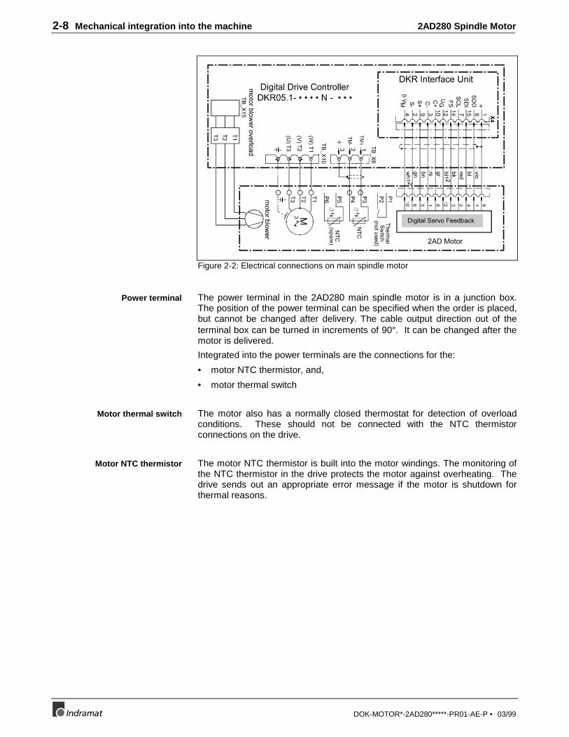
Figure 2-2: Electrical connections on main spindle motor
The power terminal in the 2AD280 main spindle motor is in a junction box.The position of the power terminal can be specified when the order is placed,but cannot be changed after delivery. The cable output direction out of theterminal box can be turned in increments of 90°. It can be changed after themotor is delivered.
Integrated into the power terminals are the connections for the:
• motor NTC thermistor, and,
• motor thermal switch
The motor also has a normally closed thermostat for detection of overloadconditions. These should not be connected with the NTC thermistorconnections on the drive.
The motor NTC thermistor is built into the motor windings. The monitoring ofthe NTC thermistor in the drive protects the motor against overheating. Thedrive sends out an appropriate error message if the motor is shutdown forthermal reasons.
Power terminal
Motor thermal switch
Motor NTC thermistor

2AD280 Spindle Motor Mechanical integration into the machine 2-9
DOK-MOTOR*-2AD280*****-PR01-AE-P • 03/99
The 2AD280 is grounded by connecting a ground wire to the ground terminallocated within the motor’s terminal box.
Figure 2-3: 3 phase ground location
The motor feedback connection is found inside the rear face bracket over thetop rear portion of the motor. An access panel must first be removed beforethe feedback connector can be mounted. The standard cable assembly usedbetween the DKR5 and 2AD280 motor is the IKS0374. The position of themotor feedback connection cannot be changed once the motor is delivered.
The 2AD280 motor blower is wired for 460…460V, 50/60 Hz and has its ownmotor protection switch. This means it functions independently of the drive.The following figure illustrates the wiring scheme.
T4T1 T7
T5T2 T8
T6T3 T9
460 V Blower Fan Connection
Wires twisted together for 460VWiring to DKR5
Figure 2-4: Motor blower wiring scheme
Grounding: Motor Power
Motor feedback
Motor blower

2-10 Mechanical integration into the machine 2AD280 Spindle Motor
DOK-MOTOR*-2AD280*****-PR01-AE-P • 03/99
2AD280 Spindle Motor Technical Data - 2AD280 3-1
DOK-MOTOR*-2AD280*****-PR01-AE-P • 03/99
3 Technical Data - 2AD280
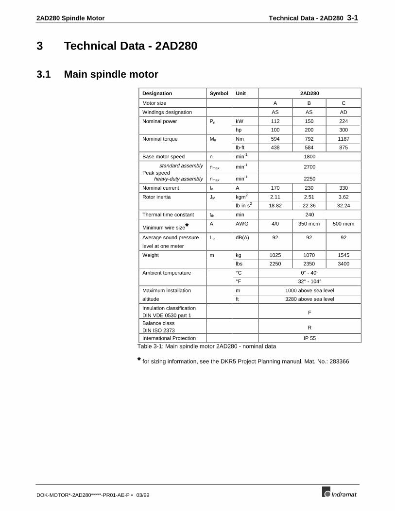
3.1 Main spindle motor
Designation Symbol Unit 2AD280
Motor size A B C
Windings designation AS AS AD
Nominal power Pn kW 112 150 224
hp 100 200 300
Nominal torque Mn Nm 594 792 1187
lb-ft 438 584 875
Base motor speed n min-1 1800
standard assembly nmax min-1 2700Peak speed
heavy-duty assembly nmax min-1 2250
Nominal current In A 170 230 330
Rotor inertia JM kgm2 2.11 2.51 3.62
lb-in-s2 18.82 22.36 32.24
Thermal time constant tth min 240
Minimum wire size* A AWG 4/0 350 mcm 500 mcm
Average sound pressure
level at one meter
Lp dB(A) 92 92 92
Weight m kg 1025 1070 1545
lbs 2250 2350 3400
Ambient temperature °C 0° - 40°
°F 32° - 104°
Maximum installation m 1000 above sea level
altitude ft 3280 above sea level
Insulation classificationDIN VDE 0530 part 1 F
Balance classDIN ISO 2373 R
International Protection IP 55
Table 3-1: Main spindle motor 2AD280 - nominal data
* for sizing information, see the DKR5 Project Planning manual, Mat. No.: 283366
3-2 Technical Data - 2AD280 2AD280 Spindle Motor
DOK-MOTOR*-2AD280*****-PR01-AE-P • 03/99
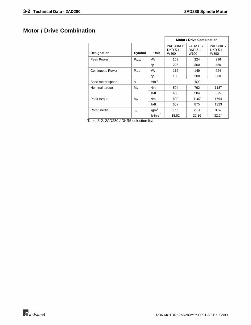
Motor / Drive CombinationMotor / Drive Combination
Designation Symbol Unit
2AD280A /DKR 5.1-W400
2AD280B /DKR 5.1-W600
2AD280C /DKR 5.1-W800
Peak Power Ppeak kW 168 224 336
hp 225 300 450
Continuous Power Pcont. kW 112 149 224
hp 150 200 300
Base motor speed n min-1 1800
Nominal torque Mn Nm 594 792 1187
lb-ft 438 584 875
Peak torque Mp Nm 890 1187 1794
lb-ft 657 875 1323
Rotor inertia JM kgm2 2.11 2.51 3.62
lb-in-s2 18.82 22.36 32.24
Table 3-2: 2AD280 / DKR5 selection list
2AD280 Spindle Motor Technical Data - 2AD280 3-3
DOK-MOTOR*-2AD280*****-PR01-AE-P • 03/99
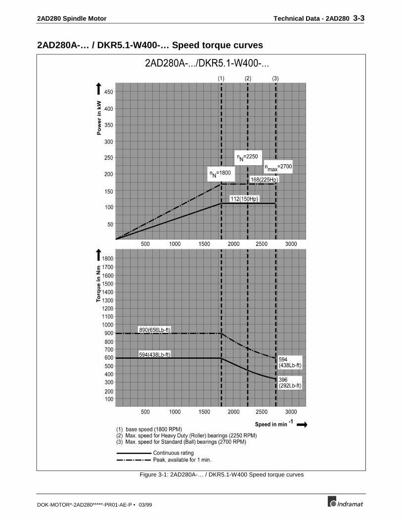
2AD280A-… / DKR5.1-W400-… Speed torque curves
Figure 3-1: 2AD280A-… / DKR5.1-W400 Speed torque curves

3-4 Technical Data - 2AD280 2AD280 Spindle Motor
DOK-MOTOR*-2AD280*****-PR01-AE-P • 03/99
2AD280B-… / DKR5.1-W600-… Speed torque curves
Figure 3-2: 2AD280B-… / DKR5.1-W600 Speed torque curves
2AD280 Spindle Motor Technical Data - 2AD280 3-5
DOK-MOTOR*-2AD280*****-PR01-AE-P • 03/99
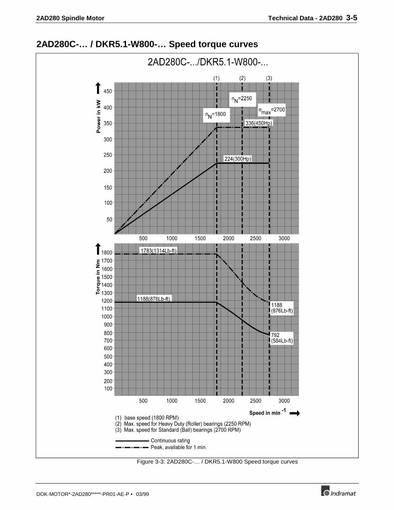
2AD280C-… / DKR5.1-W800-… Speed torque curves
Figure 3-3: 2AD280C-… / DKR5.1-W800 Speed torque curves
3-6 Technical Data - 2AD280 2AD280 Spindle Motor
DOK-MOTOR*-2AD280*****-PR01-AE-P • 03/99
Permissible shaft loading 2AD280 A/B
Figure 3-4: Main spindle motor 2AD280A/B - permissible shaft loading

2AD280 Spindle Motor Technical Data - 2AD280 3-7
DOK-MOTOR*-2AD280*****-PR01-AE-P • 03/99
Permissible shaft loading 2AD280 C
Figure 3-5: Main spindle motor 2AD280C - permissible shaft loading

3-8 Technical Data - 2AD280 2AD280 Spindle Motor
DOK-MOTOR*-2AD280*****-PR01-AE-P • 03/99
3.2 Motor blower
Designation Symbol Unit Axial blower
Air flow B Å A
blowing
Power consumption SN VA 460
Nominal voltage UN V 3 x AC, 400V, 50/60Hz
3 x AC, 460V, 60Hz
Average air volume V CFM
m3/h
1100
1870Table 3-3: Main spindle motor 2AD280 - technical data - motor blower

2AD280 Spindle Motor Technical Data - 2AD280 3-9
DOK-MOTOR*-2AD280*****-PR01-AE-P • 03/99
Figure 3-6: Front view of 2AD280 A/B
Figure 3-7: Left side view of 2AD280 A/B

3-10 Technical Data - 2AD280 2AD280 Spindle Motor
DOK-MOTOR*-2AD280*****-PR01-AE-P • 03/99
Figure 3-8: Front view of 2AD280 C
Figure 3-9: Left side view of 2AD280 C
2AD280 Spindle Motor Technical Data - 2AD280 3-11
DOK-MOTOR*-2AD280*****-PR01-AE-P • 03/99
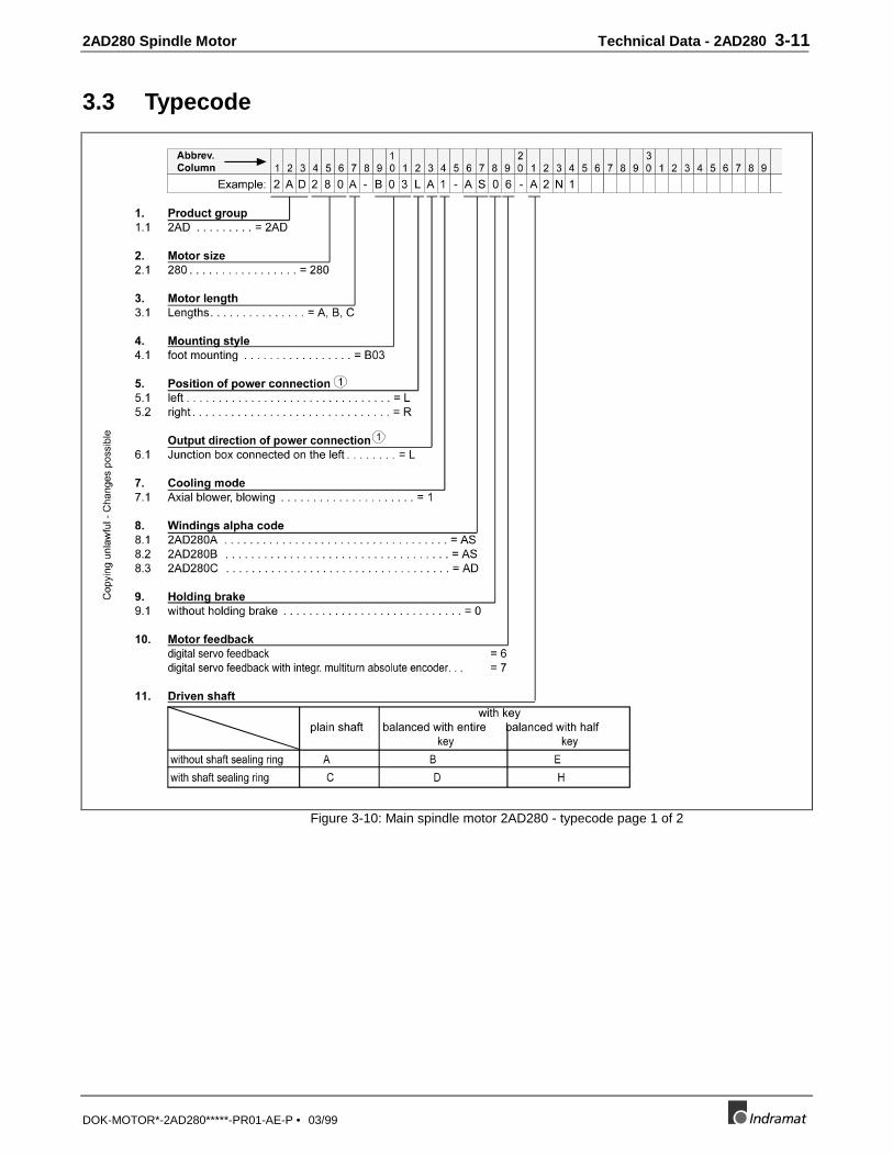
3.3 Typecode
Figure 3-10: Main spindle motor 2AD280 - typecode page 1 of 2

3-12 Technical Data - 2AD280 2AD280 Spindle Motor
DOK-MOTOR*-2AD280*****-PR01-AE-P • 03/99
Figure 3-11: Main spindle motor 2AD280 - typecode page 2 of 2

2AD280 Spindle Motor Condition at delivery 4-1
DOK-MOTOR*-2AD280*****-PR01-AE-P • 03/99
4 Condition at delivery
4.1 General Information
The merchandise is packed into a crate (2AD280) at delivery.
An envelope is attached to the crate. It contains a delivery slip and a sticker
with information about the customer, delivery slip number, consignment and
freight company. There are no other documents unless specifically requested.
The items can be unpacked without damaging them by simply removing thescrews used to assemble the crate’s panels.
4.2 Shipping papers
A single copy of the shipping papers is in an envelope included with the
delivery. These papers list merchandise by name and order designation.
If the listed contents is distributed over several transport containers, then
such will be noted on the slip or freight papers.
The packaging on each motor lists the following information:
• type designation of the motor (typecode or description)
• customer
• delivery slip number
• consignment
• freight company
(Also see section 5, “Identifying the merchandise“.)

4-2 Condition at delivery 2AD280 Spindle Motor
DOK-MOTOR*-2AD280*****-PR01-AE-P • 03/99
2AD280 Spindle Motor Identifying the merchandise 5-1
DOK-MOTOR*-2AD280*****-PR01-AE-P • 03/99
5 Identifying the merchandise
5.1 Delivery slip
One copy of the delivery slip is attached to the top of the carton. The listed
contents can be distributed over several cartons (transport containers). This
is noted on the delivery slip or consignment document.
The delivery slip identifies the merchandise by designation and item number.
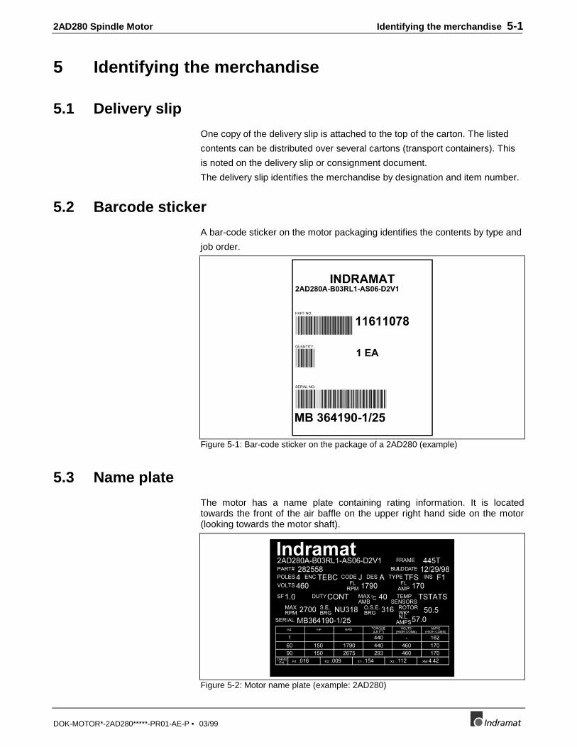
5.2 Barcode sticker
A bar-code sticker on the motor packaging identifies the contents by type and
job order.
Figure 5-1: Bar-code sticker on the package of a 2AD280 (example)
5.3 Name plate
The motor has a name plate containing rating information. It is locatedtowards the front of the air baffle on the upper right hand side on the motor(looking towards the motor shaft).
Figure 5-2: Motor name plate (example: 2AD280)

5-2 Identifying the merchandise 2AD280 Spindle Motor
DOK-MOTOR*-2AD280*****-PR01-AE-P • 03/99

2AD280 Spindle Motor Storage, Transport and Handling 6-1
DOK-MOTOR*-2AD280*****-PR01-AE-P • 03/99
6 Storage, Transport and Handling
6.1 Notes on the package
There are notes on the package concerning storage, transport and handling.These notes must be adhered.
AchtungHochwertige Elektronik
AttentionFragile Electronics
Vor Nässe schützen Nicht werfennicht belasten Nicht kantenDo not apply load Do not tipDo not drop Keep dry
Figure 6-1: Transportation safety guidelines
6.2 Storage
Motors must be stored in a dust-free environment, free from the hazard ofimpact. The permissible ambient temperature range is -20°C to +80°C.Plastic protective sleeves are placed over the motor feedback connector.They only serve to protect against moisture and mechanical damage.
6.3 Transport and handling
Warning
Motor damage during handling and mountingImproper transport and handling can damage the motor.⇒ Therefore, please note the following instructions.
Maintain the following conditions during transport and when handling:
⇒ Use suitable transport devices. Note the weight of the components(weights are listed in the individual sections of the motor under thetechnical data or on the name plate of the motor).
⇒ Use shock-dampening for transporting if excessive shock could occur.Note the limit data in section 2.1 "Maximum vibration and shock stress"
⇒ Transport in horizontal position only.⇒ Do not lift the motor at the surface cooling devices.
6-2 Storage, Transport and Handling 2AD280 Spindle Motor
DOK-MOTOR*-2AD280*****-PR01-AE-P • 03/99
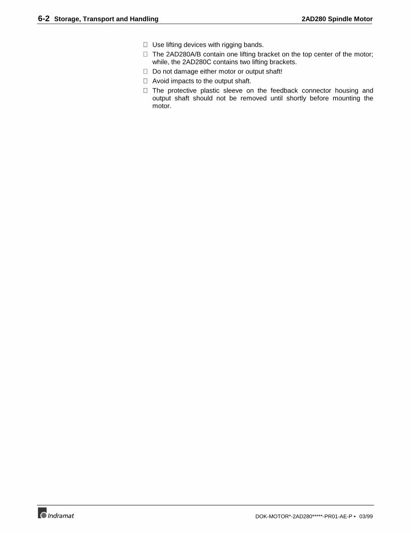
⇒ Use lifting devices with rigging bands.⇒ The 2AD280A/B contain one lifting bracket on the top center of the motor;
while, the 2AD280C contains two lifting brackets.⇒ Do not damage either motor or output shaft!⇒ Avoid impacts to the output shaft.⇒ The protective plastic sleeve on the feedback connector housing and
output shaft should not be removed until shortly before mounting themotor.
2AD280 Spindle Motor Safety guidelines for electrical drives 7-1
DOK-MOTOR*-2AD280*****-PR01-AE-P • 03/99
7 Safety guidelines for electrical drives
7.1 General information
• The safety guidelines contained in this document must, in general, beobserved. Improper handling of this machinery and non-compliance withthe warnings noted herein can cause property damage, lead to bodilyinjury or, in extreme cases, cause death. Indramat is not responsible fordamage resulting from non-compliance with the warnings and noticesspecified herein.
• The problem-free and safe operation of the drives necessitates propertransport, storage, mounting, installation and careful use andmaintenance.
• Only qualified personnel may work on or within the vicinity of the drives.Personnel is qualified if it is familiar with mounting, installation andoperation of the product and all warnings and precautionary measuresexpressed herein. Qualified means trained or permitted to switch electriccircuits on and off, to ground and label these. Personnel must be equippedwith suitable safety equipment and trained in first aid.
• Use only those replacement parts specified by manufacturer.
• The safety guidelines and conditions for the specific application must becomplied with.
• The motors are intended for mounting into machines intended forcommercial use.
• There may be no commissioning until it has been ascertained that themachines in which the product has been mounted meet the EG guide-lines 89/392/EWG (machine guidelines).
• They may only be operated if national EMC guidelines for the specificapplication are met. Within the EU, EMC guideline 89/336/EWG applies.

7-2 Safety guidelines for electrical drives 2AD280 Spindle Motor
DOK-MOTOR*-2AD280*****-PR01-AE-P • 03/99
7.2 Notes on Protection against contact with electrical parts
Parts carrying voltages in excess of 50 volts can be dangerous to humans.Electrical components can inevitably conduct dangerous voltages. Great caremust be taken when working or operating components with high voltages.
Danger
High Voltage!Danger to life or serve injury!⇒ Comply with general setup and safety guidelines when
working on high voltage facilities.⇒ After installation, check the permanent connection of the
protective conductor at all electrical components forcompliance with the terminal diagram.
⇒ Operation, even for quick measuring and testing purposes,is only permitted with permanently attached protectiveconductors of all electrical components.
⇒ Prior to accessing electrical parts with voltages greaterthan 50 volts, remove them from the power source. Secureagainst being switched back on.
⇒ Wait the discharge time of five (5) minutes after switchingoff before accessing the motor.
⇒ Points of electrical connections of the components are notto be touched when on.
⇒ Before switching the machine on, cover live parts toprevent contact.
⇒ Make sure that there is also sufficient protection againstindirect contact (as per DIN EN50178/ed.11.94, section5.3.2.3).
Warning
High current leakage!Danger to life or serve injury!⇒ Prior to switching on, connect the electrical devices of
each drive controller, supply unit and the motor with theprotective device to the grounding point.
⇒ The leakage current is greater than 3.5 mA. Thisnecessitates a permanent connection to the power supplysystem (as per DIN EN50178/Edition11.94, section5.3.2.3).
⇒ Before commissioning, even for testing purposes, alwaysconnect the protective conductor. High voltages couldotherwise occur on the housing.
2AD280 Spindle Motor Safety guidelines for electrical drives 7-3
DOK-MOTOR*-2AD280*****-PR01-AE-P • 03/99
7.3 Notes on protecting "safely-isolated low voltages"
The connections and interfaces on drive components intended for signal
voltages range from 5 to 30 volts. These electrical circuits are part of the
safely-isolated electrical circuits (safely-isolated low voltages)
Warning
High electrical voltages from improper connections!Danger to life or serve injury!⇒ Only those devices, electrical components or lines may be
connected to the signal voltages of these components ifthey are sufficiently and safely isolated as complying withset standards (per DIN EN50178/edition11.94, section5.3.2.3).
7.4 Note on handling and mounting
Warning
Danger when handling!Injury from shearing, cutting and poking.⇒ Comply with setup and safety guidelines on handling and
mounting.⇒ Use suitable mounting, transport and special tools.⇒ Squeezing and pinching can be prevented with
precautionary measures.⇒ Wear protective clothing, e.g., protective eye-wear, shoes
and gloves.⇒ Do not stand under hanging loads.⇒ Spilled liquids must be wiped up immediately.
7.5 Guidelines on protection against dangerous movements
The causes of dangerous movements can be various:
• faulty control
• software error
• component failure
• faulty wiring and cabling
• error in encoder for signals and measured values
• error caused by improper use of components
These errors can occur either directly after powering up or anytime thereafter.

7-4 Safety guidelines for electrical drives 2AD280 Spindle Motor
DOK-MOTOR*-2AD280*****-PR01-AE-P • 03/99
Danger
Danger movements!Danger to life and servere injury or property damage!⇒ The monitoring devices within the drive components
largely exclude malfunctions. This alone should not berelied upon for personnel safety. Until the built-in monitorsare activated, it should be assumed that a faulty drivemotion can occur, the extent of which depends on thenature of the problem and the operating mode. Personnelprotection is therefore dependent on and must be securedwith monitoring devices or measures that are build into themachine. These are instituted in the machine by themanufacturer after a danger and error analysis has beencomplied. This in turn takes the safety measures for themachine into consideration as well.
⇒ Personnel may not remain within the motional range of themachine. Possible measures against accidental accessingof personnel are:• protective fences
• protective railings
• protective covers
• and photo-sensors.
⇒ Make sure that fencing and covers are strong enough toabsorb maximum motional energy.
⇒ E-stop switches may be easily accessible and in theproximity of the user. Check the E-stop prior tocommissioning to make sure it is operating properly.
⇒ Secure against unintentional startups of the drive via theE-stop loop or use a starting lockout.
⇒ Prior to accessing or entering the danger zone, bring thedrives to a standstill.
⇒ Switch electrical equipment off via the main switch andsecure it against being switched back on in the case of:• maintenance and service work
• when cleaning
• prior to long operational breaks
⇒ The operation of high-frequency, remote control and radioequipment in the proximity of the machine’s electronicsand leads are to be avoided. If such must be used, thencheck, prior to initial start, both system and machine forpossible malfunctions in all situations. It may benecessary to run a special EMC check on the machine.
2AD280 Spindle Motor Mounting and installation guidelines 8-1
DOK-MOTOR*-2AD280*****-PR01-AE-P • 03/99
8 Mounting and installation guidelines• During mounting, pick the motor up only at the integrated lifting lugs using
a crane.
• Avoid shocks or impacts to the output shaft or impact stress to the shaft,as these may damage the bearing assembly of the motor.
• Screw terminal box covers tightly into place!
• The screwed caps of the connectors must be tightened!
• Ground motor to the drive!
• Following manufacturer’s circuit diagrams when wiring the motor!
• For Indramat’s circuit diagrams see "Electrical connections of main spindlemotors; project planning manual" (doc. no. 209-0042-4111). This assistsin developing circuitry diagrams for the facility.
Danger
⇒ Do not pick up the motor from the blower assembly. Theblower assembly is not designed to hold the weight of themotor.

8-2 Mounting and installation guidelines 2AD280 Spindle Motor
DOK-MOTOR*-2AD280*****-PR01-AE-P • 03/99
2AD280 Spindle Motor Service Notes 9-1
DOK-MOTOR*-2AD280*****-PR01-AE-P • 03/99
9 Service Notes
9.1 Maintenance work
The following should be performed after the first year:
• clean the motor of excess dust, chips or similar
• clean the motor blower cooling unit
• check the air circulation over the motor
Note: Follow lubrication schedule
9.2 Contacting Customer Service
To rapidly and effective eliminate problems that may occur, our Service-Hotline is available.
⇒ Prior to any telephone contacts, please make note of the following:• type data of the affected drive controllers and motors
• the problem
• fault and diagnostics display, if given
Our Service-Hotline is available 24 hours a day at 1-800-860-1055
⇒ If the motors are returned to us, then please make a copy of the followingFault Report, fill it out completely and include it with the motor.
⇒ Add the fault report to the machine documents so that the user of themachine can have access to it in the event repairs should becomenecessary.
This will ensure a rapid repair and help quickly locate any application-dependent problems.
9-2 Service Notes 2AD280 Spindle Motor
DOK-MOTOR*-2AD280*****-PR01-AE-P • 03/99
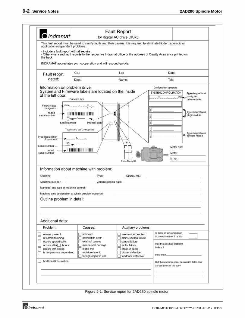
Figure 9-1: Service report for 2AD280 spindle motor
2AD280 Spindle Motor Commissioning 10-1
DOK-MOTOR*-2AD280*****-PR01-AE-P • 03/99
10 CommissioningThe commissioning process is the same for all main spindle motors. It is
described in Indramat’s main spindle motor documentation entitled, "AC main
spindle drives with regulated asynchronous motors or frameless spindle
motors, applications description", doc. no.: 209-0041-4109!

10-2 Commissioning 2AD280 Spindle Motor
DOK-MOTOR*-2AD280*****-PR01-AE-P • 03/99

2AD280 Spindle Motor Index 11-1
DOK-MOTOR*-2AD280*****-PR01-AE-P • 03/99
11 Index
2
2AD280 / DKR5 selection list............. 3-2
A
Axial shaft loads ..................................2-5
B
Balance class ....................................... 2-7Barcode sticker .................................... 5-1Bearing service life............................. 2-5
C
Commissioning.................................. 10-1Condition at delivery ........................... 4-1Construction type................................. 2-4Cooling method ................................... 2-7Customer Service................................. 9-1
D
dangerous movements ......................... 7-3Delivery slip ........................................ 5-1
E
Electrical connections.......................... 2-8Electrical features ................................ 2-7Environmental conditions.................... 2-1
F
Front view of 2AD280 A/B ................. 3-9Front view of 2AD280 C ................... 3-10
G
Grounding: Motor Power .................... 2-9
H
handling and mounting ........................ 7-3
I
Identifying the merchandise................. 5-1installation position ............................. 2-4International Protection Class ............. 2-2
L
Left side view of 2AD280 A/B............ 3-9Left side view of 2AD280 C.............. 3-10Load capacities .................................... 2-1Lubricant consumption........................ 2-6Lubrication Procedure ......................... 2-6
M
maintenance......................................... 1-1Maintenance work ............................... 9-1Mechanical Features ............................ 2-4Mechanical integration into the machine2-1Motor blower....................................... 2-9Motor blower specification.................. 3-9Motor blower wiring scheme............... 2-9Motor feedback.............................1-1, 2-9Motor name plate................................. 5-1Motor thermal switch........................... 2-8Mounting and installation guidelines .. 8-1
N
Name plate........................................... 5-1Notes on the package........................... 6-1NTC thermistor.................................... 2-8
O
Output shaft ......................................... 2-4
P
Permissible shaft load ........................ 2-5Permissible shaft loading
2AD280A/B .................................... 3-62AD280C ........................................ 3-7
Power range......................................... 1-1Power terminal..................................... 2-8Protection against contact with electrical
parts................................................. 7-2
11-2 Index 2AD280 Spindle Motor
DOK-MOTOR*-2AD280*****-PR01-AE-P • 03/99
R
Radial shaft load ..................................2-5Re-lubrication time intervals and amount2-6
S
safely-isolated low voltages................. 7-3Safety guidelines.................................. 7-1Seasonal service................................... 2-7Service Notes....................................... 9-1Service report for 2AD280 .................. 9-2
Severe service ...................................... 2-7Shipping papers ................................... 4-1Standard service................................... 2-7Storage................................................. 6-1Storage, Transport and Handling......... 6-1
T
Technical Data - 2AD280.................... 3-1Transport and handling........................ 6-1Type of protection ............................... 2-2Typecode - 2AD280 .......................... 3-11
2AD280 Spindle Motor Customer Service Locations
DOK-MOTOR*-2AD280*****-PR01-AE-P • 03/99
Customer ServiceAmericas (United States, Canada, and Latin America)
USA
Rexroth CorporationINDRAMAT Division5150 Prairie Stone ParkwayHoffman Estates, Illinois 60192
Phone: 847/645-36 00Fax: 847/645-62 01
USA
Rexroth CorporationINDRAMAT Division2110 Austin AvenueRochester Hills, Michigan 48309
Phone: 810/853-82 90Fax: 810/853-82 90
INDRAMAT Service Hotlines
USA:1-800-860-1055
Canada:1-847-645-3600(request Service Department)
Latin America:(US Phone No.) 847-645-3600(request Service Department)
Canada
Basic Technologies CorporationBurlington Division3426 Mainway DriveBurlington, OntarioCanada L7M 1A8
Phone: 905/335-55 11Fax: 905/335-41 84
Mexico
Motorización yDiseño de Controles, S.A. deC.V.Av. Dr. Gustavo Baz No. 288Col. Parque Industrial la IomaApartado Postal No. 31854060 TlalnepantlaEstado de MexicoMexico
Phone: 5/397 86 44Fax: 5/398 98 88
Argentina
Mannesmann Rexroth S.A.I.C.Division INDRAMATAcassusso 48 41/71605 Munro (Buenos Aires)Argentina
Phone: 01/756 01 4001/756 02 40
Telex: 262 66 rexro arFax: 01/756 01 36
Argentina
NakaseAsesoramiento TecnicoDiaz Velez 29291636 Olivos(Provincia de Buenos Aires)Argentina
Phone: 01/790 52 30
Brazil
Mannesmann RexrothAutomação Ltda.Divisão INDRAMATRua Georg Rexroth, 609Vila Padre AnchietaBR-09.951-250 Diadema-SPCaixa Postal 377BR-09.901-970 Diadema-SP
Phone: 011/745 90 65011/745 90 70
Fax: 011/745 90 50
Customer Service in the Americas
Asia, Australia, and Far EastAustralia
Australian Industrial MachineryServices Pty. Ltd.Unit 3/45 Horne STCampbellfield VIC 2061Australia
Phone: 03/93 59 0228Fax: 03/93 59 02886
China
Rexroth (China) Ltd.Shanghai OfficeRoom 206Shanghai Intern. Trade Centre2200 Yanan Xi LuShanghai 200335P.R. China
Phone: 021/627 55 333Fax: 021/627 55 666
China
Rexroth (China) Ltd.Shanghai Parts & ServiceCentre199 Wu Cao Road, Hua CaoMinhang DistrictShanghai 201 103P.R. China
Phone: 021/622 00 058Fax: 021/622 00 068
China
Rexroth (China) Ltd.1430 China World Trade Centre1, Jianguomenwai AvenueBeijing 100004P.R. China
Phone: 010/50 50 380Fax: 010/50 50 379
China
Rexroth (China) Ltd.A-5F., 123 Lian Shan StreetSha He Kou DistrictDalian 116 023P.R. China
Phone: 0411/46 78 930Fax: 0411/46 78 932
Hong Kong
Rexroth (China) Ltd.19 Cheung Shun Street1st Floor, Cheung Sha Wan,Kowloon, Hong Kong
Phone: 741 13 51/-54 or741 14 30
Telex: 3346 17 GL REX HXFax: 786 40 19
786 07 33
India
Mannesmann Rexroth (India)Ltd.INDRAMAT DivisionPlot. 96, Phase IIIPeenya Industrial AreaBangalore - 560058India
Phone: 80/839 21 0180/839 73 74
Telex: 845 5028 RexBFax: 80/839 43 45
Japan
Rexroth Co., Ltd.INDRAMAT DivisionI.R. BuildingNakamachidai 4-26-44Tsuzuki-ku, Yokohama 226Japan
Phone: 045/942-72 10Fax: 045/942-03 41
Korea
Rexroth-Seki Co Ltd.1500-12 Da-Dae-DongSaha-Gu, Pusan, 604-050Korea
Phone: 051/264 90 01Fax: 051/264 90 10
Korea
Seo Chang Corporation Ltd.Room 903, Jeail Building44-35 Yoido-DongYoungdeungpo-KuSeoul, Korea
Phone: 02/780-82 07 ~9Fax: 02/784-54 08
Customer Service in Asia, Australia, and the Far East
Customer Service Locations 2AD280 Spindle Motor
DOK-MOTOR*-2AD280*****-PR01-AE-P • 03/99
EuropeAustria
G.L.Rexroth Ges.m.b.H.Geschäftsbereich INDRAMATHägelingasse 3A-1140 Wien
Phone: 1/9852540-400Fax: 1/9852540-93
Austria
G.L.Rexroth Ges.m.b.H.Geschäftsbereich INDRAMATRandlstraße 14A-4061 Pasching
Phone: 07229/4401-36Fax: 07229/4401-80
Belgium
Mannesmann Rexroth N.V.-S.A.INDRAMAT DivisionIndustrielaan 8B-1740 Ternat
Phone: 02/5823180Fax: 02/5824310
Denmark
BEC Elektronik ASZinkvej 6DK-8900 Randers
Phone: 086/447866Fax: 086/447160
England
Mannesmann Rexroth Ltd.INDRAMAT Division4 Esland Place, Love LaneCirencester, Glos GL7 1YG
Phone: 01285/658671Fax: 01285/654991
Finland
Rexroth Mecman OYRiihimiehentie 3SF-01720 Vantaa
Phone: 0/848511Fax: 0/846387
France
Rexroth - Sigma S.A.Division INDRAMATParc des Barbanniers 4,Place du VillageF-92632 Gennevilliers Cedex
Phone: 1/41475430Fax: 1/47946941
France
Rexroth - Sigma S.A.Division INDRAMAT91, Bd 1 Joliot CurieF-69634 Venissieux - Cx
Phone: 78785256Fax: 78785231
France
Rexroth - Sigma S.A.Division INDRAMAT270, Avenue de lardenneF-31100 Toulouse
Phone: 61499519Fax: 61310041
Italy
Rexroth S.p.A.Divisione INDRAMATVia G. Di Vittoria, 1I-20063 Cernusco S/N.MI
Phone: 02/92365-270Fax: 02/92108069
Italy
Rexroth S.p.A.Divisione INDRAMATVia Borgomanero, 11I-10145 Torino
Phone: 011/7712230Fax: 011/7710190
Netherlands
Hydraudyne Hydrauliek B.V.Kruisbroeksestraat 1aP.O. Box 32NL-5280 AA Boxtel
Phone: 04116/51951Fax: 04116/51483
Spain
Rexroth S.A.Centro Industrial SantiagoObradors s/nE-08130 Santa Perpetua deMogoda (Barcelona)
Phone: 03/718 68 51Telex: 591 81Fax: 03/718 98 62
Spain
Goimendi S.A.División IndramatJolastokieta (Herrera)Apartado 11 37E-San Sebastion, 20017
Phone: 043/40 01 63Telex: 361 72Fax: 043/39 93 95
Sweden
AB Rexroth MecmanINDRAMAT DivisionVaruvägen 7S-125 81 Stockholm
Phone: 08/727 92 00Fax: 08/64 73 277
Switzerland
Rexroth SADépartement INDRAMATChemin de l`Ecole 6CH-1036 Sullens
Phone: 021/731 43 77Fax: 021/731 46 78
Switzerland
Rexroth AGGeeschäftsbereich INDRAMATGewerbestraße 3CH-8500 Frauenfeld
Phone: 052/720 21 00Fax: 052/720 21 11
Russia
Tschudnenko E.B.Arsenia 22153000 IvanovoRussia
Phone: 093/22 39 633
Customer Service in Europe
GermanyCentral Sales Region
INDRAMAT GmbHBgm.-Dr.-Nebel-Str. 2D-97816 Lohr am Main
Phone: 09352/40-0Fax: 09352/40-4885
Eastern Sales Region
INDRAMAT GmbHBeckerstraße 31D-09120 Chemnitz
Phone: 0371/3555-0Fax: 0371/3555-230
Western Sales Region
INDRAMAT GmbHHansastraße 25D-40849 Ratingen
Phone: 02102/4318-0Fax: 02102/41315
Northern Sales Region
INDRAMAT GmbHFährhausstraße 11D-22085 Hamburg
Phone: 040/227126-16Fax: 040/227126-15
Southern Sales Region
INDRAMAT GmbHRidlerstraße 75D-80339 München
Phone: 089/540138-30Fax: 089/540138-10
Southwestern Sales Region
INDRAMAT GmbHBöblinger Straße 25D-71229 Leonberg
Phone: 07152/972-6Fax: 07152/972-727
INDRAMAT Service Hotline
INDRAMAT GmbHPhone: 0172/660 040 6
-or-
Phone: 0171/333 882 6
Customer Service in Germany

2AD280 Spindle Motor Customer Service Locations
DOK-MOTOR*-2AD280*****-PR01-AE-P • 03/99
Notes: