Abstract - This paper discusses the designing & implementation of 3-Axis Single Sided Circuit Drawing Machine using Arduino development board based on the application of computerised numerical controller(CNC). Open source software used are Android IDE and Benbox, Computer, Arduino ATMega328p Board, CNC Shield, Motor Driver & Servo Motors are the components used in this project. The main aim of this project is to reduce the bulkiness of PCB which give rise to new technology of Flexible Electronics by enabling to print the circuits on any surface. The designing of this project is to reduce error and increase accuracy & productivity. The idea behind this project is prototype electronics circuits on every surface using conductive ink. In this project Autodesk Eagle is used to build PCB Layout Key Words: Computerised Numerical Control(CNC); Benbox; Arduino IDE; Conductive ink; Autodesk Eagle; Flexible Electronics
INTRODUCTION CNC Machining is a process to manufacturing industries that uses computer for the movement of tools. Computers outputs a numeric code which is used by the controller to interpret or plot the location to move the tools. That numeric codes are called as G-Codes. G-Codes are special generated codes by computer which consists of x-axis, y-axis & z-axis location. Autodesk Eagle is used to create a PCB schematic & its layouts. It is used to create gerber file, mirror image of the board layout which are used as an input to etch the PCB. The mirror image output by Autodesk Eagle is provided to Benbox . Benbox is an open source software installed in computer which can create G Codes on its own of a two dimensional picture. The two dimensional picture can be an image, PCB layout or any document file. Benbox have the feature to set the baud rate, configure the controller, spinning speed, time, intensity, step of each axis. Benbox uses its algorithm to set the dimensions of any two dimensional object fed to the software. Benbox outputs the hex file. Arduino IDE is used to program the Arduino Microcontroller to specify the serial communication with the computer, specify the motors. Conductive ink is a good conductor of electricity. It allows electric current to flow through it. It is mainly made of graphite materials. It can be used to prototype electronic circuts without etching it on PCBs. 3 Axis PCB
Drawing Machine is used to create such PCBs design on a single sheet of paper. A. Objective
● To create electronic circuits at a cheaper rate
● An altenative of breadboard to test various circuits
● Research & Development cost behind building any circuit reduces
● It can be easily operable
● It is easy to interface
● It consumes less power
B. Methodology
● Research about the new ways to prototype
● Component Selection and Testing
● Hardware Implementation
● Designing of PCB Layout
● Create the hex file of the image
● Programming the Controller using IDE
● Burning the program
● Debugging the circuit
● Configure the Microcontroller to PC to access G-code
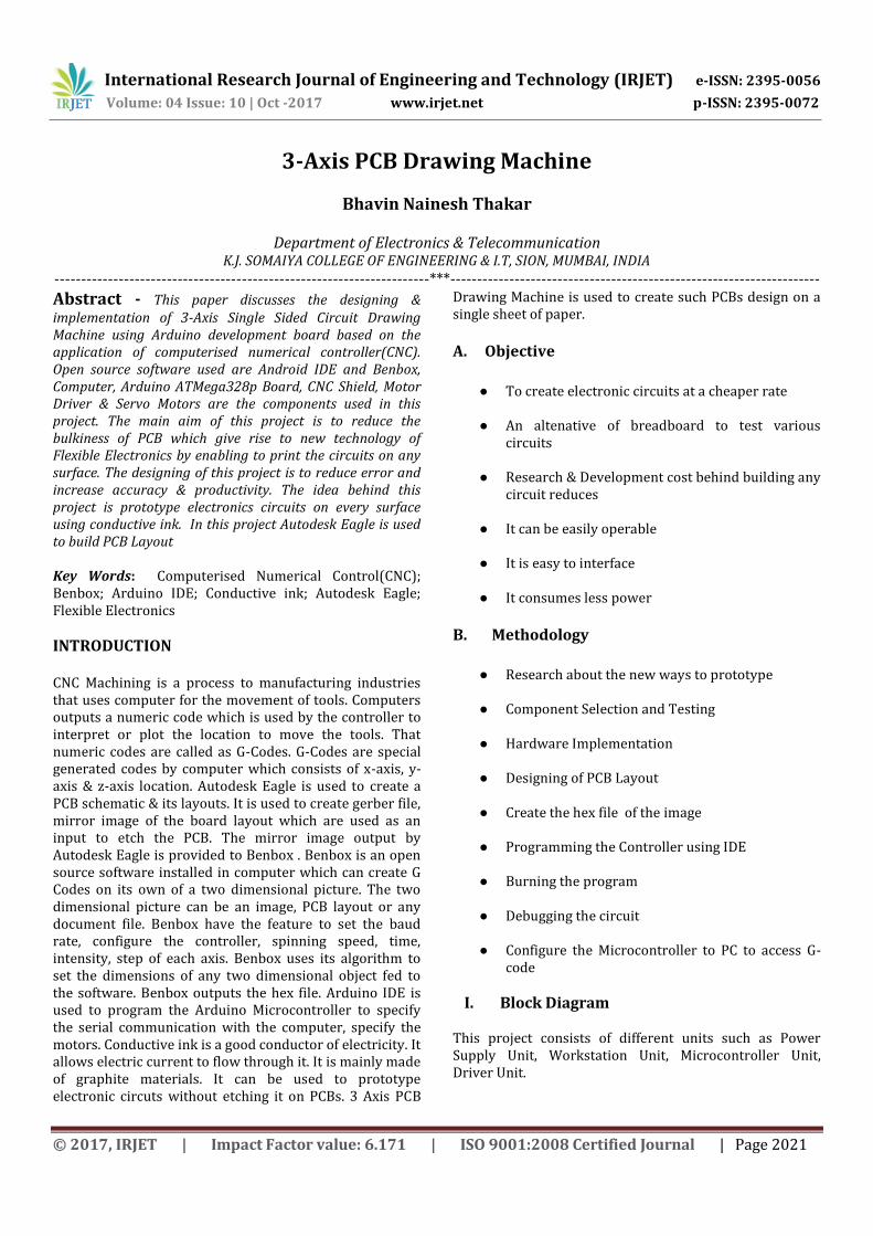
I. Block Diagram This project consists of different units such as Power Supply Unit, Workstation Unit, Microcontroller Unit, Driver Unit.
International Research Journal of Engineering and Technology (IRJET) e-ISSN: 2395-0056
Volume: 04 Issue: 10 | Oct -2017 www.irjet.net p-ISSN: 2395-0072
FIG-1: Block diagram of 3-Axis PCB Drawing Machine
1. Power Supply unit Power Supply unit consists of various signal conditioning circuitry. It is used to step down various voltages which can be used to fed to various other components of the circuits. Power supply unit is designed in such a way that each component can access proper current to function. The total power supply require is 12v,2A
2. Workstation unit Workstation unit consists of various software like Autodesk Eagle, Arduino IDE, Benbox . Autodesk Eagle. It consists of various drivers installed that are used for communication between microcontroller & itself.
A. Autodesk Eagle Autodesk Eagle is a software which is used to design the board layout of any circuit. It is available in Windows, Mac & Linux operating system. It consists of various features like modular design blocks, multisheet schematics, Electrical Rule Checking(ERC), realtime deisgn synchronization, obstacle avoidance routing, auto router, BGA fanout. An example of 5v,1A power supply circuit is prepared. This layout is exported into mirror image file
Fig-2: PCB Design in Autodesk Eagle
B. Benbox Benbox is software which is used to generate gcodes form the given two dimensional picture. It is only available for Windows operating system. It is mainly use for the application of Laser Engraver. It has various features like configure the microcontroller, setting speed, intensity and steps for the engraving. The mirror image output from Autodesk Eagle is imported and with its default algorithm it creates coordinates and generates an hex file.
International Research Journal of Engineering and Technology (IRJET) e-ISSN: 2395-0056
Volume: 04 Issue: 10 | Oct -2017 www.irjet.net p-ISSN: 2395-0072
C. Arduino IDE Arduino IDE is the software that gives software development tools for Arduino development boards. In this project we have to interface motors and check for serial communication so the Flowchart will be:
.
Fig-4: Flowchart of the project
The program is burnt into Arduino Board with proper pinouts for x, y & z motors.
3. Arduino Uno R3(ATMEGA-328) Arduino Uno is a microcontroller board based on ATmega328. Its operating voltage is +5V. it consists of 14 digital i/o pins. It can withstand input voltage from 7-20 V. The DC Current per pin 40ma. It has 32kb of flash memory. It operating default clock frequency is 16MHz
Fig-4: Arduino UNO R3
4. CNC Shield V3 CNC Shield V3.0 can be used as drive expansion board for engraving machine, 3D printer and other devices. There’re 4 slots in the board for stepper motor driver modules, can drive 4 stepper motors. It has an input voltage of 8-36v.
Fig-5: CNC Shield V3
International Research Journal of Engineering and Technology (IRJET) e-ISSN: 2395-0056
Volume: 04 Issue: 10 | Oct -2017 www.irjet.net p-ISSN: 2395-0072
5. Motor Driver Circuit(A4988) The input of motor driver is provided from CNC Shield V3. The motor driver circuit is placed on CNC Shield circuit. Motor driver circuit(A4988) is a 28pin circuit. Its maximum supply voltage is 35v & maximum current rating is 2A. It takes three inputs from microcontroller. 1st input is the supply voltage given to enable(EN)pin to energize the IC, & 2nd & 3rd input decides the direction of rotation of motor. In this project, we have used 3 motor driver circuit, one for each axis.
Fig-6:Motor Driver(A4988)
6. Motors In this project, we use two dvd driver motor for x & y-axis. The part number of stepper motor used is 15RF073K. Its step angle is 18 degrees. Its holding torque is 25g.cm. It has a rated current of 0.24A at no load and 0.70A at full load. The supply voltage required is 5V.
Fig-7:Stepper Motor(15RF073K)
The motor used for Z-Axis is servo motor MG90s. Its has a step angle of 180 degrees. Its holding torque is 1.8kgf.cm. The supply voltage required is 5V. It has rated current of 0.22A at no load & 0.65A at full load. So the total supply required by all the motors at full load is 2A
Fig-8: Servo motor(Mg90s)
7. Output Component The output device used in this project is conductive ink pen. The other devices which can be used are drill, cutter, laser etc. the output devices depends on the application.
II. Project Implementation
A. Hardware Implementation In this project, the essential parts needed for the project is disassembled from DVD writer. The Parts required for mechanical movement and holding the body is cut and glued on the acrylic sheet. The components required are stepper motor, rod and the mechanical part that is required to hold the rod steady. The rod and the motor are glued on the body in such a way that free movement of motor takes place across the rod. This will build x –axis motion. For y-axis DVD driver body is placed on the x axis. z-axis is prepared by joining the servo motor at the x axis of the body. The controller is placed on the other side of the acrylic sheet. Proper connection are made to the motor.
International Research Journal of Engineering and Technology (IRJET) e-ISSN: 2395-0056
Volume: 04 Issue: 10 | Oct -2017 www.irjet.net p-ISSN: 2395-0072
B. Software Implementation In this project, Arduino Uno is used. So to code it, Arduino IDE. The code consists of functions like stating pinout of the motors, checking for the incoming data on serial pin from workstation, Decoding the incoming data, turning motors on as per the logic. It is Burnt in Arduino UNO. Benbox is used to automatically generate G-codes. The step rate mentioned in the code is matched with the Benbox. It is used to configure Controller & Computer for serial communication. The PCB design prepared by Autodesk Eagle is imported into Benbox to generate G-code and then sent to controller to generate logic to control motors
III. Conclusion This paper has presented the development of a low cost PCB layout drawing machine. As it is collaboration of both hardware and software the work load reduces. G-codes is used to plot the location easily. Making a small machine will help to develop PCB at very cheap rate and make it flexible to develop circuits on any medium.
IV. References
1) V.K. Pabolu and K.N.H. Srinivas, “Design and
implementation of a three dimensional CNC machine",2010.
2) Allegro MicroSystems - A4988 datasheet, “DMOS Microstepping Driver with Translator And Overcurrent Protection” https://www.pololu.com/file/download/a4988_DMOS_microstepping_driver_with_translator.pdf?file_id=0J450
3) ATmega328p datasheet by Atmel http://www.atmel.com/Images/Atmel-42735-8-bit-AVR-Microcontroller-ATmega328-328P_Datasheet.pdf
4) Xu, Y. Li, J. Sun, and S. Wang, “Research and development of open CNC system based on PC and motion controller”,2012
5) Brian W. Evans, “Arduino Programming Notebook”,2007


![de partido a su piscina… - BINDER · Tipo BGA 160 BGA 215 BGA 275 BGA 320 BGA 430 BGA 550 BGA 600 BGA 1200 Tensión de conexión [VAC] 230 230 230 230 230 230 230 230 Rango de frecuencia](https://static.documents.pub/doc/80x56/5c132e8509d3f26c7c8c5e0d/de-partido-a-su-piscina-binder-tipo-bga-160-bga-215-bga-275-bga-320-bga-430.jpg)


