Sains Malaysiana 48(6)(2019): 1239–1249 http://dx.doi.org/10.17576/jsm-2019-4806-11 3-Dimensional Electric Field Distributions of Castellated and Straight Dielectrophoresis Electrodes for Cell Separation (Pengagihan Medan Elektrik 3-Dimensi Elektrod Dielektroforesis Kekota dan Lurus untuk Pembahagian Sel) FARAHDIANA WAN YUNUS, MUHAMMAD RAMDZAN BUYONG, JUMRIL YUNAS, BURHANUDIN YEOP MAJLIS & AZRUL AZLAN HAMZAH* ABSTRACT This paper discusses the 3-dimensional (3D) electric field distributions on the surface and across the bulk volume of dielectrophoresis (DEP) electrodes. The importance of obtained high electric field is to ensure that biological particles will be able to separate even at low voltage potentials in order to avoid damage to the biological particles. Two electrodes - straight and castellated, were designed using the COMSOL Multiphysics Software Version 5.2 to compare the surface distribution and volume electric fields along the x, y and z axes. The results showed that castellated electrodes showcased higher electric fields for both the surface and volume factors along all axes. The maximum value of volume electric field results was 3.94×10 5 V/m along the x-axis, 3.80×10 5 V/m along the y-axis and 1.65×10 5 V/m along the z-axis. The maximum value of surface electric fields distributions was 3.39×10 5 V/m along the x-axis, 2.87×10 5 V/m along the y-axis and 1.14×10 5 V/m along the z-axis. Additionally, the uniformity of the electric field lines distribution from the COMSOL Multiphysics also indicated that castellated electrodes have a much higher uniformity. The experimental results showed that the castellated electrodes separated particles much faster at 69 s, as compared to straight electrodes at 112 s. Henceforth, this has proven that castellated electrodes have a high electric field as it separates much faster as compared to straight electrodes. Keywords: Biological particles; castellated electrodes; DEP; dielectrophoresis; electric fields; straight electrodes ABSTRAK Kajian ini membincangkan aliran medan elektrik 3-dimensi (3D) pada permukaan dan isi padu elektrod dieletroforesis (DEP). Medan elektik begitu penting bagi memastikan sel zarah biologi mampu untuk dipisahkan walaupun pada voltan yang rendah bagi mengelakkan kerosakan pada sel zarah tersebut. Dua elektrod, lurus dan kekota direka bentuk menggunakan perisian COMSOL Multiphysics versi 5.2 bagi membandingkan taburan medan elektrik di permukaan elektrod dan isi padu elektrod pada paksi x, y dan z. Keputusan menunjukkan bahawa elektrod kekota mempunyai medan elektrik yang tertinggi pada kedua-dua medan elektrik permukaan dan medan elektrik isi padu. Keputusan pada medan elektrik berisi padu adalah bernilai 3.94×10 5 V/m pada paksi x, 3.80×10 5 V/m pada paksi y dan 1.65×10 5 V/m pada paksi z, manakala keputusan pada medan elektrik permukaan adalah 3.39×10 5 V/m pada paksi x, 2.87×10 5 V/m paksi y dan 1.14×10 5 V/m pada paksi z. Tambahan pula, keputusan COMSOL Multiphysic juga menjelaskan keseragaman medan elektrik pada elektrod kekota adalah lebih tinggi. Keputusan menunjukkan elektrod kekota berjaya mengasingkan zarah dengan lebih cepat iaitu pada 69 s berbanding elektrod lurus pada 112 s. Oleh yang demikian, ini telah membuktikan bahawa elektrod kekota mempunyai daya medan elektrik yang tinggi setelah ia berjaya memisahkan sampel sel zarah tersebut lebih laju daripada elektrod lurus. Kata kunci: DEP; dielektroforesis; elektrod kekota; elektrod lurus; medan elektrik; zarah biologi INTRODUCTION For decades, dielectrophoresis (DEP) has been widely used in clinical analysis, across many research areas, for medical treatment, and drug development. In fact, DEP is well known to be used for separation (Rabiatul et al. 2018), manipulations (Tada et al. 2018), transportation (Ismail et al. 2017), cell sorting and trapping (Qian et al. 2014) and handling biological particles (Díaz & Payen 2013; Morgan et al. 1999). On the other hand, previous literature works by Buyong et al. (2016) elucidated that it was possible to use DEP as artificial kidney membranes. The separation of particles occurs when the particles respond toward different frequencies when an alternating current (AC) is applied. Examples of biological particles that can be separated are stem cells (Pethig et al. 2010), red blood cells (Yunus et al. 2017), proteins (Seyedi & Matyushov 2018), DNA (Nakano et al. 2011), yeast cells (Çetin et al. 2009), breast cancer cells (Becker et al. 1995), bacteria (Pethig 2010; Stevens & Jaykus 2004), and platelets (Piacentini et al. 2011a). Research by Qian et al. (2014) has shown that DEP is a much more practical solution for use in the separation of cells due to a high electric field. Table 1 shows five methods
3-Dimensional Electric Field Distributions of Castellated and Straight Dielectrophoresis Electrodes for Cell Separation
(Pengagihan Medan Elektrik 3-Dimensi Elektrod Dielektroforesis Kekota dan Lurus untuk Pembahagian Sel)
FARAHDIANA WAN YUNUS, MUHAMMAD RAMDZAN BUYONG, JUMRIL YUNAS, BURHANUDIN YEOP MAJLIS & AZRUL AZLAN HAMZAH*
ABSTRACT
This paper discusses the 3-dimensional (3D) electric field distributions on the surface and across the bulk volume of dielectrophoresis (DEP) electrodes. The importance of obtained high electric field is to ensure that biological particles will be able to separate even at low voltage potentials in order to avoid damage to the biological particles. Two electrodes - straight and castellated, were designed using the COMSOL Multiphysics Software Version 5.2 to compare the surface distribution and volume electric fields along the x, y and z axes. The results showed that castellated electrodes showcased higher electric fields for both the surface and volume factors along all axes. The maximum value of volume electric field results was 3.94×10⁵ V/m along the x-axis, 3.80×10⁵ V/m along the y-axis and 1.65×10⁵ V/m along the z-axis. The maximum value of surface electric fields distributions was 3.39×10⁵ V/m along the x-axis, 2.87×10⁵ V/m along the y-axis and 1.14×10⁵ V/m along the z-axis. Additionally, the uniformity of the electric field lines distribution from the COMSOL Multiphysics also indicated that castellated electrodes have a much higher uniformity. The experimental results showed that the castellated electrodes separated particles much faster at 69 s, as compared to straight electrodes at 112 s. Henceforth, this has proven that castellated electrodes have a high electric field as it separates much faster as compared to straight electrodes.
Kajian ini membincangkan aliran medan elektrik 3-dimensi (3D) pada permukaan dan isi padu elektrod dieletroforesis (DEP). Medan elektik begitu penting bagi memastikan sel zarah biologi mampu untuk dipisahkan walaupun pada voltan yang rendah bagi mengelakkan kerosakan pada sel zarah tersebut. Dua elektrod, lurus dan kekota direka bentuk menggunakan perisian COMSOL Multiphysics versi 5.2 bagi membandingkan taburan medan elektrik di permukaan elektrod dan isi padu elektrod pada paksi x, y dan z. Keputusan menunjukkan bahawa elektrod kekota mempunyai medan elektrik yang tertinggi pada kedua-dua medan elektrik permukaan dan medan elektrik isi padu. Keputusan pada medan elektrik berisi padu adalah bernilai 3.94×10⁵ V/m pada paksi x, 3.80×10⁵ V/m pada paksi y dan 1.65×10⁵ V/m pada paksi z, manakala keputusan pada medan elektrik permukaan adalah 3.39×10⁵ V/m pada paksi x, 2.87×10⁵ V/m paksi y dan
1.14×10⁵ V/m pada paksi z. Tambahan pula, keputusan COMSOL Multiphysic juga menjelaskan keseragaman medan elektrik pada elektrod kekota adalah lebih tinggi. Keputusan menunjukkan elektrod kekota berjaya mengasingkan zarah dengan lebih cepat iaitu pada 69 s berbanding elektrod lurus pada 112 s. Oleh yang demikian, ini telah membuktikan bahawa elektrod kekota mempunyai daya medan elektrik yang tinggi setelah ia berjaya memisahkan sampel sel zarah tersebut lebih laju daripada elektrod lurus.
Kata kunci: DEP; dielektroforesis; elektrod kekota; elektrod lurus; medan elektrik; zarah biologi
INTRODUCTION
For decades, dielectrophoresis (DEP) has been widely used in clinical analysis, across many research areas, for medical treatment, and drug development. In fact, DEP is well known to be used for separation (Rabiatul et al. 2018), manipulations (Tada et al. 2018), transportation (Ismail et al. 2017), cell sorting and trapping (Qian et al. 2014) and handling biological particles (Díaz & Payen 2013; Morgan et al. 1999). On the other hand, previous literature works by Buyong et al. (2016) elucidated that it was possible to use DEP as artificial kidney membranes. The separation of
particles occurs when the particles respond toward different frequencies when an alternating current (AC) is applied. Examples of biological particles that can be separated are stem cells (Pethig et al. 2010), red blood cells (Yunus et al. 2017), proteins (Seyedi & Matyushov 2018), DNA (Nakano et al. 2011), yeast cells (Çetin et al. 2009), breast cancer cells (Becker et al. 1995), bacteria (Pethig 2010; Stevens & Jaykus 2004), and platelets (Piacentini et al. 2011a). Research by Qian et al. (2014) has shown that DEP is a much more practical solution for use in the separation of cells due to a high electric field. Table 1 shows five methods
1240
and comparisons which are controllability, operation, efficiency, cost and resulting damage for the separation cells. As for controllability, Table 1 shows that all, except the microfluidic method has a strong controllability, while the operation factor is hard for three methods, with the exception of the electric fields and microfluidic methods. Moreover, the efficiency of the electric fields and microfluidics methods were rated high, and they are low in cost, while the other methods are high in cost and low in efficiency. However, the electric fields method displayed slight damage, while the microfluidic method had little damage. Therefore, electric fields are a better method to use as it is easy to handle, takes on low damage impact and is much cheaper, as shown in Table 1. Moreover, in previous research works, castellated electrodes and interdigitated castellated electrodes have been frequently used to test living cells such as blood cells (Becker et al. 1995; Piacentini et al. 2011a; Yang et al. 2000). All three studies (Becker et al. 1995; Piacentini et al. 2011b; Yang et al. 2000) used glass substrates in their research. In Becker et al. (1995), whole blood cells were separated from cancer cells by using electrodes made with gold, while Yang et al. (2000) used human leukocytes to separate the major mixture of human white blood cells. Additionally, for Piacentini et al. (2011b), platinum electrodes were used to separate platelets and red blood cells. Nevertheless, in this research, two electrodes were designed, namely castellated and straight. The electrodes were designed with membranes in between them. The aim of this research was to separate biological particles from the membranes for use as an artificial kidney. It has been noted in a previous research work by (Burham et al. 2014a, 2014b) that the silicon membranes had some flaws as the biological particles tend to clog. Therefore, application of dielectrophoresis will be used to improve and separate the biological particles. Thus, both electrodes were compared to find better distribution and high electric fields using the COMSOL Multyphysics Software for the separation of biological cells for the artificial kidney membranes. In the later stages, both electrodes were fabricated and tested using red blood cells.
THEORY OF DIELECTROPHORESIS (DEP)
Dielectrophoresis refers to the movement of particles in a non-uniform electric field due to a time variation (AC) (Buyong et al. 2014b; Yunus et al. 2017). Dielectrophoresis depends strictly on the particle shape and size, the
frequency of the electric field, the medium and the particle’s electrical properties. Dielectric particles behave as an effective dipole with dipole moment ρ, proportional to the electric field E (Buyong et al. 2014b):
ρ α E (1)
The proportional constant depends on the geometry of the dielectric particle. In the presence of an electric field gradient, the force on a dipole can be represented as (Buyong et al. 2014b):
F = (ρ . d ) E (2)
where ρ is the constant of a dipole moment vector; d is del vector; and E is the external electric field. When the two equations are combined, (FDEP) acts as a homogenous particle suspended in an electric field gradient given by (Buyong et al. 2014b):
FDEP = 2πεmedium R3 CMF (dE2) (3)
where dE is the gradient of the rms electric field; r is the radius of particle; and εm is the permittivity of the suspending medium. The defining component in the dielectrophoresis reaction is the Clausius-Mossotti factor (CMF) which is written as (Buyong et al. 2014a):
εmedium and εparticle represent the complex permittivity of the particles for the medium and cells, respectively (Buyong et al. 2014a).
MATERIALS AND METHODS
COMSOL MULTIPHYSICS SOFTWARE
The COMSOL Multiphysics software version 5.2 was used in this research to determine the distribution of the electric field. The AC/DC electric fields module was selected in this study (Marsi et al. 2014). The electrodes were designed using a 3D model in order to find the maximum and minimum values of the electric fields and electric field line distributions from the surface and volume of the electrodes. The study was carried out at a frequency of 500 kHz with a 10V potential for both electrodes. A frequency of 500 kHz was used in this study due to the response of
TABLE 1. Comparison of particle control methods. Adapted from Qian et al. (2014)
the particles which were attracted to the electrodes at this frequency. This resulted in the particles movements which were separated from the membranes. Materials such as aluminum (Al), silicon (Si), and silicon nitride (SiN3) were identified in this study as well.
DESIGN OF ELECTRODES
There are two types of electrodes; castellated (Abidin et al. 2013) and straight. Both electrodes are made of aluminum and deposited with silicon membranes etched in between them. Silicon nitride is used as a passivation layer to prevent contact between the aluminum electrodes and the silicon membranes. Figure 1(a), 1(b) and 1(c) shows the design of the electrodes using the simulation software.
STRAIGHT ELECTRODES
Straight electrodes are the simplest of known electrode designs. Straight electrodes have been used for many years, but in this research the electrodes were improved by adding membranes in the center of the electrodes for use in the artificial kidney membrane application. Figure 1(b) shows the magnified image of the straight electrode design.
CASTELLATED ELECTRODES
The design of castellated electrodes is quite similar to that of the straight electrodes. The differences between the two
designs are the additions of some finger electrodes for the castellated electrodes. Figure 1(c) shows an image of the castellated electrode design.
FABRICATIONS
Electrodes were made using a 4-inch silicon wafer (Marsi et al. 2014) that had been deposited with silicon nitride on the top and bottom sides of the wafer. The fabrications steps were divided into two parts; silicon membranes and electrodes.
FABRICATION OF SILICON MEMBRANES
Figure 2(a), 2(b), and 2(c) shows the fabrication steps of the silicon membranes. Photolithography was carried out using a positive resist to form a pattern of the intended membranes. Subsequently, the silicon nitride was etched away using a buffer oxide etching (BOE) solution to open the window for the membranes (Burham et al. 2015; Hamzah et al. 2013).
FABRICATION OF ELECTRODES
Figure 2(c) and 2(d) shows the second part of fabrication step. Photolithography was performed to pattern the electrode’s design. Aluminum was deposited (Mmm et al. 2018) on the top of the silicon nitride (Hamzah et al. 2008; Yunas et al. 2009). A lift off step was carried
FIGURE 1. a) Design of electrodes using the COMSOL Multiphysics Software 5.2, b) The magnified image for straight electrodes, and c) The magnified image for castellated electrodes
1242
FIGURE 2. a) silicon wafer, b) pattern of window membranes are exposed to uv light, c) BOE of nitride to open the window of membranes, d) metal was deposited on top of the silicon nitride, e) lift off process took place to form
the electrodes patterned, and f) Setup of experiment. Adapted from: (Yunus et al. 2018)
1243
out to remove any unwanted metal and finally form the required design of the electrodes. Lastly, annealing process (Shamsudin et al. 2018) was done to improve the structure of aluminums.
SETUP OF EXPERIMENTS
The electrodes were put under a microscope and a drop of blood was placed on the electrode. The electrodes were then connected to the AC function generator at 10V with a frequency of 500 kHz as the particles started to respond toward the electric field. The time taken for the particles to respond until they cleared the membrane was measured. An illustration of experiment setup is shown in Figure 2(f).
RESULTS AND DISCUSSION
ELECTRIC FIELDS
The simulations result of the electric fields for both castellated and straight electrodes will be discussed in this section. The results have been separated into three parts; the surface of electric field, electric field line distributions and volume of the electric field. Additionally, electric fields were studied along the x-axis, y-axis and z-axis in order to determine the best electrodes for use as an artificial kidney.
MAXIMUM AND MINIMUM VALUES OF VOLUME ELECTRIC FIELD AT X, Y AND Z AXES FOR STRAIGHT ELECTRODES
AND CASTELLATED ELECTRODES
Figure 3 shows the results of the maximum and minimum volumes of the electric fields across all three axes. Figure 3(a) and 3(b) shows the results from the x-axis. The maximum value of the electric field is shown at the edge of the straight electrodes at a value of 2.14×10⁵ V/m, while the minimum value was recorded at -2.18×10⁵ V/m, as shown in Figure 3(a). On the other hand, Figure 3(b) shows that the maximum value of the electric field for the castellated electrode along the x-axis was at 3.94×10⁵ V/m, while the minimum value was at -3.95×10⁵ V/m. The results along the y-axis are as shown in Figure 3(c) and 3(d). The simulation results showed that the volume of the electric fields are highest at 1.36×10⁵ V/m and lowest at -2.18×10⁵ V/m. Furthermore, the maximum and minimum electric fields for the castellated electrodes are as shown in Figure 3(d). The results dictate that the maximum values are at 3.80×10⁵ V/m while the minimum recorded value was at -4.40×10⁵ V/m. Lastly, Figure 3(e) and 3(f) depicts the results from the z-axis. The straight electrode results are shown in Figure 3(e). The volume of the electric field along the z-axis has a maximum at 8.96×10⁴ V/m and a minimum at -7.26×10⁴
V/m. The maximum and minimum values of the volume electric field using the castellated electrodes are as shown in Figure 3(f). The maximum recorded value was 1.65×10⁵
V/m, and the minimum value was -1.79×10⁵ V/m.
1244
FIGURE 3. a) Maximum and minimum value of volume electric field at x-axis for straight electrodes, b) Maximum and minimum value of volume electric field at x-axis for castellated electrodes, c) Maximum and minimum value of volume electric field at y-axis for straight electrodes, d) Maximum and minimum value of volume electric field at y-axis for castellated electrodes, e) Maximum and minimum value of volume electric field at z-axis for straight electrodes, and f) Maximum and minimum value of volume electric field at z-axis for castellated electrodes
1245
Thus, in this section, it is shown that the castellated electrodes have a much higher electric field along all three axes.
ELECTRIC FIELD LINES DISTRIBUTIONS AT X, Y AND Z AXES FOR STRAIGHT AND CASTELLATED ELECTRODES
The electric field lines of the straight and castellated electrodes were compared along the x, y and z axes as shown in Figure 4. Color scales depict that the higher electric fields will show a much brighter colors, while lower electric fields are shown as faded colors. The results are discussed as follows. The results in Figure 4 shows that the castellated electrodes along all three axes have a much brighter color of electric field lines, thus, it indicates that the castellated electrodes have a higher electric field. The electric fields across the castellated electrodes are strongest at the edges of the electrode fingers as shown in Figure 4(b), 4(d), and 4(f). On the other hand, the straight electrodes showed that the electric field distribution lines were brighter at the edges of the silicon membranes, as shown in Figure 4(a), 4(c), and 4(e). The results along the z-axis for both
the castellated and straight electrodes are seen to be the weakest as compared to the other two axes. However, the castellated electrodes were seen to have much better results as all three axes showed much better electric field lines.
MAXIMUM AND MINIMUM VALUES OF SURFACE ELECTRIC FIELD DISTRIBUTION AT X, Y AND Z AXIS FOR STRAIGHT
AND CASTELLATED ELECTRODES
Figure 5 illustrates the comparisons between the straight and castellated electrodes for the surface electric field distributions along the x, y and z axes. Maximum and minimum values and electric fields distribution uniformity were compared to find the best electric field between the two electrodes. Figure 5(a) examines the results from the x-axis for the straight electrodes, while Figure 5(b) depicts the results of the castellated electrodes. The maximum value for the straight electrode was recorded at 1.86×10⁵ V/m, while the minimum recorded value was 1.76×10⁵ V/m. The results showed that the castellated electrodes have a maximum value of 3.39×10⁵ V/m and a minimum value of -3.39×10⁵ V/m for the electric fields.
FIGURE 4. a) Volume electric field distribution lines at x-axis for straight electrodes, b) Volume electric field distribution lines at x-axis for castellated electrodes, c) Volume electric field distribution lines at y-axis for straight electrodes, d) Volume electric field distribution lines at y-axis for castellated electrodes, e) Volume electric field distribution lines at
z-axis for straight electrodes, and f) Volume electric field distribution lines at z-axis for castellated electrodes
1246
Figure 5(c) and 5(d) showcases the results from the y-axis. The maximum electric field for the straight electrodes was at 1.27×10⁵ V/m while the minimum was at -2.12×10⁵ V/m. The maximum electric field was at 2.87×10⁵ V/m and the minimum value was at -2.86×10⁵ V/m for the castellated electrode. The results across the z-axis is shown in Figure 5(e) and 5(f) for the straight electrode, of which the maximum recorded value was at 6.88×10⁴ V/m and the minimum value was at -4.71×10⁴ V/m. The maximum value for the castellated electrode was at 1.14×10⁵ V/m and the minimum was at -1.12×10⁵ V/m. The castellated electrode shows a much better distribution across all three axes, as shown in Figure 5(b), 5(d) and 5(f). The electric field distributions strength is shown to be much stronger for the castellated electrodes as the amount of orange shades were brighter and had a
much more stable and uniform distribution as compared to the straight electrode in Figure 5(a), 5(c) and 5(e). Based on the results shown for the maximum and minimum values of the surface electric fields, volume electric fields and electric field lines distributions, the castellated electrodes have a much higher electric field along all 3 axes. Despite the fact that at the z-axis the electric field is less uniform, it still had a much higher electric field compared to that of the straight electrode. A summarization of the results is shown in Table 2. It also has been noted that the electric fields strength, electric field line and electric fields distributions are dependent on the distance between the electrodes. The closer the distance between the electrodes, the stronger the electric field strength that will produced. Hence, stronger electric field strength, higher electric field lines and more uniform of electric field distributions will be achieved.
FIGURE 5. a) Surface electric field distribution at x-axis for straight electrodes, b) Surface electric field distribution at x-axis for castellated electrodes, c) Surface electric distribution lines at y-axis for straight electrodes, d) Surface electric field distribution at
y-axis for castellated electrodes, e) Surface electric field distribution at z-axis for straight electrodes, and f) Surface electric field distribution at z-axis for castellated electrodes
1247
Equation 5 shows the connection between the distance of the electrodes and the electric field,
E = F / q (5)
where E is the electric field strength; F is the force; and q is the charge. E is proportional to to force and inversely proportional to q. When a potential is supplied toward the electrodes, two charges are produced,
F = k q Q / d2 (6)
where k is the constant; Q is the source charge; q is the test charge; and d is the separation distance. Equations 5 and 6 were combined to form (7),
E = k Q / d2 (7)
where E is inversely proportional to d; of which Q is the charge; k is the constant and d is the separation distance. Accordingly, the straight and castellated electrodes were designed to have fingers which had a distance between electrodes which were much closer, as compared to those of the straight electrodes. Thus, the castellated had resulted in a much higher values of the electric field, stronger presence of the electric field and uniform electric field distributions lines.
TESTING
The electrodes were compared using experiment set ups to prove that the castellated electrodes were much more
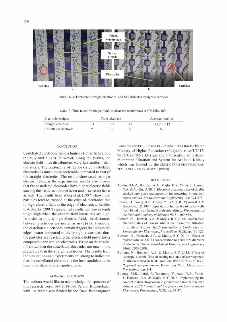
effective than the straight electrodes for cell separations. Figure 6 shows the results and discussions with regards to the types of electrodes used in the experiments. Both electrodes were tested using red blood cells as particles. The results showed that for the straight electrodes, the particles moved toward the right and left of the electrodes, as the simulation results indicated a high electric field on the left and right side of electrodes. On the other hand, for the castellated electrodes, the particles moved slowly towards the high electric field, toward the edge of the electrode’s fingers. As the electric fields generates 10 V at a frequency of 500 kHz, particles near the straight electrode started to react towards the electric field and slowly moved toward the electrodes. At 112 s, the silicon membranes started to clear. On the other hand, particles near the castellated electrodes reacted to the electric field and cleared the membranes at 69 s. Particles were measured three times and the average time was calculated. Table 3 shows the average time taken of the particles to clear the membranes. The experiment section and Figure 2(f) explain how the particles was introduced as well as the experiment set up. At 500 kHz, the particles responded to the positive DEP, which is why the particles are moved toward the electrodes. Referring to (1), the particles are likely dependent on the frequency and electric field, therefore, different frequencies will result in a different DEP movement. It has been proven that by using castellated electrodes, the membranes seperated much faster due to the high electric field, strong magnitude of electric field and uniform electric field lines distributions influence as shown through the simulation results.
TABLE 2. Summarize results of volume and surface electric fields
Types of electrodes
Value of electric fieldCastellated Straight
Volume E-field distribution x-axis (V/m)
Maximum electric fieldMinimum electric field
3.94×10⁵
-3.95×1052.14×105
-2.18×10⁵
Surface E-field distribution x-axis (V/m)
Maximum electric fieldMinimum electric field
3.39×10⁵
-3.39×1051.86×105
-1.76×10⁵
Surface electric field uniformity x-axis Uniformity Very uniform Uniform
Volume E-field distribution y-axis (V/m)
Maximum electric fieldMinimum electric field
3.80×10⁵
-4.40×1051.36×105
-2.18×10⁵
Surface E-field Distribution y-axis (V/m)
Maximum electric fieldMinimum electric field
2.87×10⁵
-2.86×1051.27×105
-2.12×10⁵
Surface electric field uniformity y-axis Uniformity Uniform Less uniform
Volume E-field distribution z-axis (V/m)
Maximum electric fieldMinimum electric field
1.65×10⁵
-1.79×1050.89×105
-0.73×10⁵
Surface E-field distribution z-axis (V/m)
Maximum electric fieldMinimum electric field
1.14×10⁵
-1.12×1050.69×105
-0.47×10⁵
Surface electric field uniformity z-axis Uniformity Less uniform Non-uniform
1248
CONCLUSION
Castellated electrodes have a higher electric field along the x, y and z axes. However, along the y-axis, the electric field lines distributions were less uniform than the z-axis. The uniformity of the z-axis on castellated electrodes is much more preferable compared to that of the straight electrodes. The results showcased stronger electric fields, as the experimental results also proved that the castellated electrodes have higher electric fields causing the particles to move faster and to separate faster as well. The results from Wang et al. (1997) shown that particles tend to trapped at the edge of electrodes due to high electric field at the edge of electrodes. Besides that, Markx (2007) represented results that forces tends to get high when the electric field intensities are high. In order to obtain high electric field, the distances between electrodes are nearer as in (5)-(7). Therefore, the castellated electrodes contain fingers that makes the edges nearer compared to the straight electrodes, thus, the particles are reacted to the electric field move faster compared to the straight electrodes. Based on the results, it’s shown that the castellated electrodes are much more preferable than the straight electrodes. The results from the simulations and experiments are strong to indicators that the castellated electrode is the best candidate to be used in artificial kidney applications.
ACKNOWLEDGEMENTS
The authors would like to acknowledge the sponsors of this research work, DPP-2018-006 Peranti Bioperubatan with IOT which was funded by the Dana Pembangunan
Penyelidikan PTJ, HICOE-AKU-95 which was funded by the Ministry of Higher Education (Malaysia), PRGS/1/2017/TK05/UKM/02/1 Design and Fabrication of Silicon Membrane Filtration and System for Artificial Kidney which was funded by the SKIM GERAN PENYELIDIKAN PEMBANGUNAN PROTOTAIP (PRGS).
REFERENCES
Abidin, H.E.Z., Hamzah, A.A., Majlis, B.Y., Yunas, J., Hamid, N.A. & Abidin, U. 2013. Electrical characteristics of double stacked ppy-pva supercapacitor for powering biomedical mems devices. Microelectronic Engineering 111: 374-378.
Becker, F.F., Wang, X.B., Huang, Y., Pethig, R., Vykoukal, J. & Gascoyne, P.R. 1995. Separation of human breast cancer cells from blood by differential dielectric affinity. Proceedings of the National Academy of Sciences 92(3): 860-864.
Burham, N., Hamzah, A.A. & Majlis, B.Y. 2014a. Mechanical characteristics of porous silicon membrane for filtration in artificial kidney. IEEE International Conference on Semiconductor Electronics, Proceedings, ICSE. pp. 119-122.
Burham, N., Hamzah, A.A. & Majlis, B.Y. 2014b. Effect of hydrofluoric acid (HF) concentration to pores size diameter of silicon membrane. Bio-Medical Materials and Engineering 24(6): 2203-2209.
Burham, N., Hamzah, A.A. & Majlis, B.Y. 2015. Effect of isopropyl alcohol (IPA) on etching rate and surface roughness of silicon etched in KOH solution. RSM 2015-2015 IEEE Regional Symposium on Micro and Nano Electronics, Proceedings. pp. 1-4.
Buyong, M.R., Larki, F., Takamura, Y., Aziz, N.A., Yunas, J., Hamzah, A.A. & Majlis, B.Y. 2016. Implementing the concept of dielectrophoresis in glomerular filtration of human kidneys. IEEE International Conference on Semiconductor Electronics, Proceedings, ICSE. pp. 33-37.
TABLE 3. Time taken for the particles to clear the membranes at 500 kHz, 10V
Electrode designs Time taken (s) Average time (s)Straight electrodeCastellated electrode
13175
16172
4360
111.7 ≃ 11269
FIGURE 6. a) Fabricated straight electrodes, and b) Fabricated straight electrodes
a. b.
1249
Buyong, M.R., Aziz, N.A., Hamzah, A.A. & Majlis, B.Y. 2014a. Dielectrophoretic characterization of array type microelectrodes. IEEE International Conference on Semiconductor Electronics, Proceedings, ICSE (Dc). pp. 240-243.
Buyong, M.R., Aziz, N.A., Hamzah, A.A., Wee, M.F.M.R. & Majlis, B.Y. 2014b. Finite element modeling of dielectrophoretic microelectrodes based on a array and ratchet type. IEEE International Conference on Semiconductor Electronics, Proceedings, ICSE. pp. 3: 236-239.
Çetin, B., Kang, Y., Wu, Z. & Li, D. 2009. Continuous particle separation by size via AC-dielectrophoresis using a lab-on-a-chip device with 3-D electrodes. Electrophoresis 30(5): 766-772.
Díaz, R. & Payen, S. 2013. Biological cell separation using dielectrophoresis in a microfluidic device. Www-Bsac.Eecs.Berkeley.Edu. pp. 1-4.
Hamzah, A.A., Yunas, J., Majlis, B.Y. & Ahmad, I. 2008. Sputtered encapsulation as wafer level packaging for isolatable MEMS devices: A technique demonstrated on a capacitive accelerometer. Sensors 8(11): 7438-7452.
Hamzah, A.A., Zainal Abidin, H.E., Yeop Majlis, B., Mohd Nor, M., Ismardi, A., Sugandi, G., Tiong, T.Y., Dee, C.F. & Yunas, J. 2013. Electrochemically deposited and etched membranes with precisely sized micropores for biological fluids microfiltration. Journal of Micromechanics and Microengineering 23(7): 074007.
Ismail, S., Mahmood, N.H. & Razak, M.A.A. 2017. Optimization of interdigitated electrodes in electric field distribution and thermal effect. Journal of Telecommunication, Electronic and Computer Engineering 9(3): 85-89.
Markx, G.H. 2007. Tissue engineering with electric fields: Investigation of the shape of mammalian cell aggregates formed at interdigitated oppositely castellated electrodes. Electrophoresis 28(21): 3821-3828.
Marsi, N., Majlis, B.Y., Hamzah, A.A. & Mohd-Yasin, F. 2014. The mechanical and electrical effects of MEMS capacitive pressure sensor based 3C-SiC for extreme temperature. Journal of Engineering 2014: 715167.
Mmm, G.O., Mmm, G.O., Psf, M.M.M. & Psf, M.M.M. 2018. The effect of ZnO loading for the enhancement of PSF/ZnO-GO mixed matrix membrane performance. Sains Malaysiana 47(9): 2035-2045.
Morgan, H., Hughes, M.P. & Green, N.G. 1999. Separation of submicron bioparticles by dielectrophoresis. Biophysical Journal 77(1): 516-525.
Nakano, A., Chao, T.C., Camacho-Alanis, F. & Ros, A. 2011. Immunoglobulin G and bovine serum albumin streaming dielectrophoresis in a microfluidic device. Electrophoresis 32(17): 2314-2322.
Pethig, R. 2010. Dielectrophoresis: Status of the theory, technology, and applications. Biomicrofluidics 4(2): 1-35.
Pethig, R., Menachery, A., Pells, S. & De Sousa, P. 2010. Dielectrophoresis: A review of applications for stem cell research. Journal of Biomedicine and Biotechnology 2010: Article ID. 182581.
Piacentini, N., Mernier, G., Tornay, R. & Renaud, P. 2011a. Separation of platelets from other blood cells in continuous-flow by dielectrophoresis field-flow-fractionation. Biomicrofluidics 5(3): 1-8.
Piacentini, N., Mernier, G., Tornay, R. & Renaud, P. 2011b. Separation of platelets from other blood cells in continuous-flow by dielectrophoresis field-flow-fractionation. Biomicrofluidics 5(3): 034122-034122-8.
Qian, C., Huang, H., Chen, L., Li, X., Ge, Z., Chen, T., Yang, Z. & Sun, L. 2014. Dielectrophoresis for bioparticle manipulation. International Journal of Molecular Sciences 15(10): 18281-18309.
Rabiatul, N., Tajul, A., Abd, N. & Majlis, B.Y. 2018. Separation of micro engineered particle using dielectrophoresis technique. 2018 IEEE International Conference on Semiconductor Electronics (ICSE) 2018(8): 69-72.
Shamsudin, F.M., Radiman, S., Abdullah, Y. & Hamid, N.A. 2018. The effect of annealing to the hardness of high Y2O3 -oxide dispersion strengthened (ODS) ferritic steels. Sains Malaysiana 47(1): 189-193.
Seyedi, S.S. & Matyushov, D.V. 2018. Protein dielectrophoresis in solution. Journal of Physical Chemistry B 122(39): 9119-9127.
Stevens, K.A. & Jaykus, L.A. 2004. Bacterial separation and concentration from complex sample matrices: A review. Critical Reviews in Microbiology 30(1): 7-24.
Tada, S., Omi, Y. & Eguchi, M. 2018. Analysis of the dielectrophoretic properties of cells using the isomotive AC electric field. Biomicrofluidics 12(4): 044103.
Wang, X.B., Huang, Y., Gascoyne, P.R.C. & Becker, F.F. 1997. Dielectrophoretic manipulation of particles. IEEE Transactions on Industry Applications 33(3): 660-669.
Yang, J., Huang, Y., Wang, X.B., Becker, F.F. & Gascoyne, P.R.C. 2000. Differential analysis of human leukocytes by dielectrophoretic field-flow-fractionation. Biophysical Journal 78(5): 2680-2689.
Yunus, F.W., Hamzah, A.A., Norzin, M.S., Buyong, M.R. & Yunas, J. 2018. Dielectrophoresis: Iron dificient anemic red blood cells for artificial kidney purposes. 2018 IEEE International Conference on Semiconductor Electronics (ICSE). pp. 5-8.
Yunus, F.W., Hamzah, A.A., Buyong, M.R., Yunas, J. & Majlis, B.Y. 2017. Negative charge dielectrophoresis by using different radius of electrodes for biological particles. Proceedings of the 2017 IEEE Regional Symposium on Micro and Nanoelectronics, RSM 2017: 84-87.
Institute of Microenegineering and Nanoelectronics (IMEN)Universiti Kebangsaan Malaysia43600 UKM Bangi, Selangor Darul EhsanMalaysia