Instructions GRACO INC. P.O. BOX 1441 MINNEAPOLIS, MN 55440–1441 Copyright 1999, Graco Inc. is registered to I.S. EN ISO 9001 HYDRA-CAT R VARIABLE RATIO Proportioning Pumps *Includes Automatic Pressure Relief Valves, Check Valves, Pressure Gauges and Regulators Basic Operation for Use with Configured Models 309024C WARNING Plural Component Materials Hazard Graco Inc. does not manufacture or supply any of the reactive chemical materials that may be used in this equipment and is not responsible for their effects. Be- cause of the vast number of chemicals that could be used and their varying chemical reaction, before us- ing this equipment the buyer and the user should de- termine all facts relating to the materials used, includ- ing any of the potential hazards involved. Particular inquiry and investigation should be made into the po- tential dangers relating to toxic fumes, fires, explo- sions, reaction times, and exposure of human beings to the individual components or their resultant mix- tures. Graco assumes no responsibility for loss, dam- age, expense or claims for bodily injury or property damage, direct or consequential, arising from the use of such chemical components. Mounting as Shown: Monark Air Motor and Standard Manifold Shown Important Safety Instructions Read all warnings and instructions in this manual. Save these instructions.
Transcript
Instructions
GRACO INC. P.O. BOX 1441 MINNEAPOLIS, MN 55440–1441Copyright 1999, Graco Inc. is registered to I.S. EN ISO 9001
Plural Component Materials HazardGraco Inc. does not manufacture or supply any of thereactive chemical materials that may be used in thisequipment and is not responsible for their effects. Be-cause of the vast number of chemicals that could beused and their varying chemical reaction, before us-ing this equipment the buyer and the user should de-termine all facts relating to the materials used, includ-ing any of the potential hazards involved. Particularinquiry and investigation should be made into the po-tential dangers relating to toxic fumes, fires, explo-sions, reaction times, and exposure of human beingsto the individual components or their resultant mix-tures. Graco assumes no responsibility for loss, dam-age, expense or claims for bodily injury or propertydamage, direct or consequential, arising from the useof such chemical components.
Mounting as Shown:Monark Air Motor and Standard Manifold Shown
Important Safety InstructionsRead all warnings and instructions in this manual.Save these instructions.
President� Air Motors 306982Monark� Air Motors 307043Bulldog� Air Motors 307049Viscount I 307654Displacement Pump 307430Displacement Pumps 307431Displacement Pumps 307944Displacement Pumps 684004Configurator Product Order Form 309025Displacement Pumps 306936Displacement Pumps 307862
Manual No.
309024 3
WarningsWarning Symbol
WARNINGThis symbol alerts you to the possibility of seriousinjury or death if you do not follow the instructions.
Caution Symbol
CAUTIONThis symbol alerts you to the possibility of damage toor destruction of equipment if you do not follow theinstructions.
WARNING
INSTRUCTIONS
EQUIPMENT MISUSE HAZARD
Equipment misuse can cause the equipment to rupture, malfunction, or start unexpectedly and resultin serious injury.
� This equipment is for professional use only.
� Read all instruction manuals, warnings, tags, and labels before operating the equipment.
� Use the equipment only for its intended purpose. If you are uncertain about usage, call your Gracodistributor.
� Do not alter or modify this equipment. Use only genuine Graco parts and accessories.
� Check the equipment daily. Repair or replace worn or damaged parts immediately.
� See Configurator Product Order Form 309025 for important pressure rating information. Themaximum working pressure of each model is also shown on the pump identification plate. Be surethat all dispensing equipment and accessories are rated to withstand the maximum working pres-sure of your pump. Do not exceed the maximum working pressure of the lowest rated systemcomponent.
� Never operate the pump without the automatic pressure relief valves and drainage kits installed.These valves relieve fluid pressure through a drain port at the bottom of the valve if the displace-ment pump pressure exceeds the working pressure.
� Never exceed the recommended working pressure or the maximum air inlet pressure stated onyour pump or in the Configurator Product Order Form 309025.
� Do not lift pressurized equipment.
� Use only Graco approved hoses. Do not remove hose spring guards, which help protect the hosefrom rupture caused by kinks or bends near the couplings.
� Route the hoses away from the traffic areas, sharp edges, moving parts, and hot surfaces. Do notexpose Graco hoses to temperatures above 180�F (82�C) or below –40�F (–40�C).
� Do not use the hoses to pull the equipment.
� Use fluids and solvents that are compatible with the equipment wetted parts. See the TechnicalData section of all the equipment manuals. Read the fluid and solvent manufacturer’s warnings.
� Comply with all applicable local, state and national fire, electrical and other safety regulations.
4 309024
WARNINGSKIN INJECTION HAZARD
Spray from the spray gun, hose leaks, or ruptured components can inject fluid into your body andcause extremely serious injury, including the need for amputation. Splashing fluid in the eyes or on theskin can also cause serious injury.
� Fluid injected into the skin might look like just a cut, but it is a serious injury. Get immediate medi-cal surgical treatment.
� Do not point the gun/valve at anyone or at any part of the body.
� Do not put your hand or fingers over the spray tip/nozzle.
� Do not stop or deflect fluid leaks with your hand, body, glove, or rag.
� Do not “blow back” fluid; this is not an air spray system.
� Check the gun diffuser operation weekly. Refer to the gun manual.
� Always have the trigger guard on the gun when dispensing.
� Be sure the gun/valve trigger safety operates before dispensing.
� Lock the gun/valve trigger safety when you stop dispensing.
� Follow the Pressure Relief Procedure on page 15 whenever you: are instructed to relieve pres-sure; stop spraying/dispensing; clean, check, or service the equipment; and install or clean thespray tip/nozzle.
� Tighten all fluid connections before operating the equipment.
� Check the hoses, tubes, and couplings daily. Replace worn, damaged, or loose parts immediately.Do not repair high pressure couplings; you must replace the entire hose.
� Fluid hoses must have spring guards on both ends, to help protect them from rupture caused bykinks or bends near the couplings.
FIRE, EXPLOSION AND ELECTRIC SHOCK HAZARD
Improper grounding, poor air ventilation, open flames, or sparks can cause a hazardous condition andresult in fire, explosion, or electrostatic shock and other serious injury.
� Ground the equipment, the object being dispensed, and all other electrically conductive objects inthe dispense area. Proper grounding dissipates static electricity generated in the equipment. Referto System Grounding on page 9.
� Provide fresh air ventilation to avoid the buildup of flammable fumes from solvent or material.
� Do not use the heater with flammable liquids, such as those having flash points below 200� F(93� C).
� Extinguish all open flames or pilot lights in the dispense area.
� Do not turn on or off any light switch in the dispense area.
� Do not use this equipment with flammable liquids.
� Keep the dispense area free of debris, including solvent, rags, and gasoline.
� Do not smoke in the dispense area.
� Do not operate a gasoline engine within the spray area.
� If there is any static sparking or you feel an electric shock while using the equipment, stop dis-pensing immediately. Do not use the equipment until you have identified and corrected theproblem.
309024 5
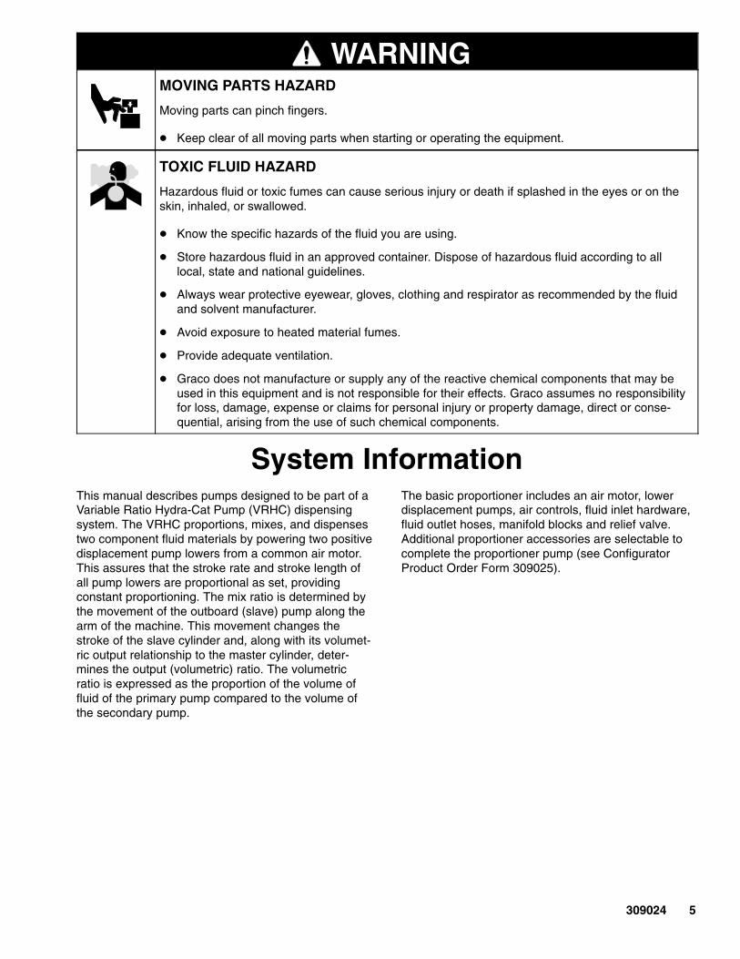
WARNINGMOVING PARTS HAZARD
Moving parts can pinch fingers.
� Keep clear of all moving parts when starting or operating the equipment.
TOXIC FLUID HAZARD
Hazardous fluid or toxic fumes can cause serious injury or death if splashed in the eyes or on theskin, inhaled, or swallowed.
� Know the specific hazards of the fluid you are using.
� Store hazardous fluid in an approved container. Dispose of hazardous fluid according to alllocal, state and national guidelines.
� Always wear protective eyewear, gloves, clothing and respirator as recommended by the fluidand solvent manufacturer.
� Avoid exposure to heated material fumes.
� Provide adequate ventilation.
� Graco does not manufacture or supply any of the reactive chemical components that may beused in this equipment and is not responsible for their effects. Graco assumes no responsibilityfor loss, damage, expense or claims for personal injury or property damage, direct or conse-quential, arising from the use of such chemical components.
System InformationThis manual describes pumps designed to be part of aVariable Ratio Hydra-Cat Pump (VRHC) dispensingsystem. The VRHC proportions, mixes, and dispensestwo component fluid materials by powering two positivedisplacement pump lowers from a common air motor.This assures that the stroke rate and stroke length ofall pump lowers are proportional as set, providingconstant proportioning. The mix ratio is determined bythe movement of the outboard (slave) pump along thearm of the machine. This movement changes thestroke of the slave cylinder and, along with its volumet-ric output relationship to the master cylinder, deter-mines the output (volumetric) ratio. The volumetricratio is expressed as the proportion of the volume offluid of the primary pump compared to the volume ofthe secondary pump.
The basic proportioner includes an air motor, lowerdisplacement pumps, air controls, fluid inlet hardware,fluid outlet hoses, manifold blocks and relief valve.Additional proportioner accessories are selectable tocomplete the proportioner pump (see ConfiguratorProduct Order Form 309025).
6 309024
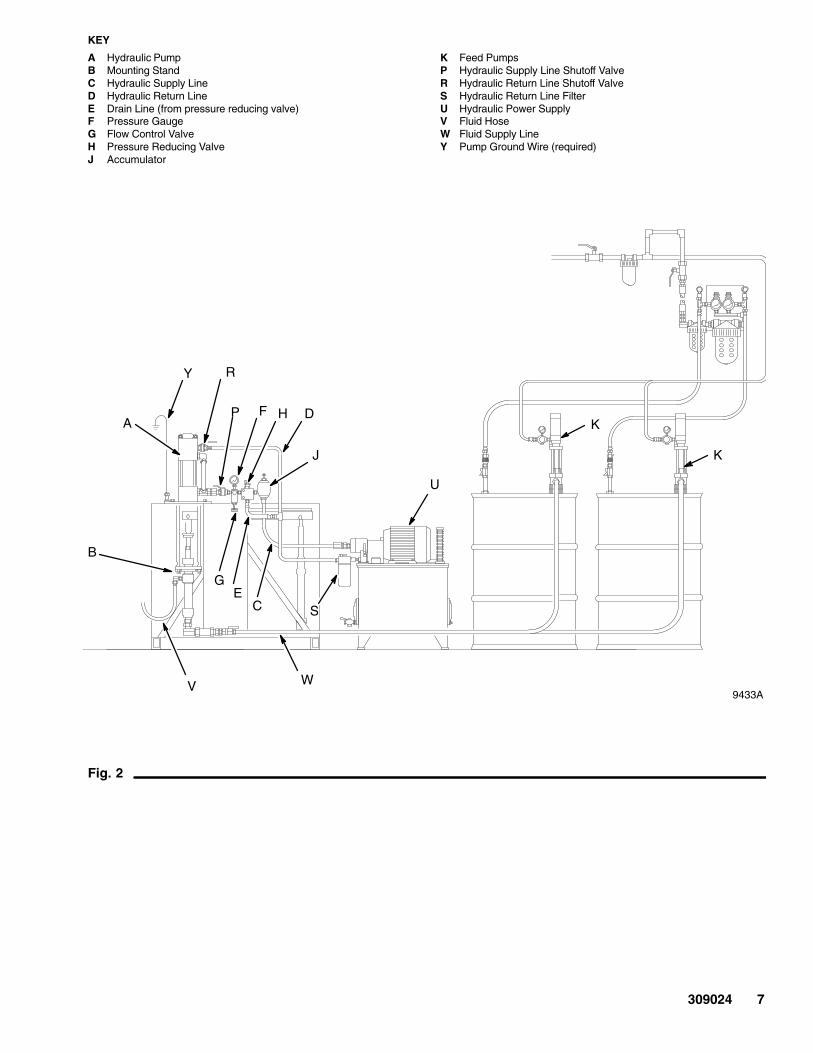
Typical InstallationAbout Typical InstallationsThe typical installations shown below and on page 7are only guidelines to setting up a complete VRHCsystem. For clarity, various components are shown inthe correct order but may not be shown in the exactposition of the installed system. For assistance indesigning your system, contact your nearest Gracorepresentative.
NOTE: When pressure feeding the proportioningpump, mount fluid pressure gauges (J) at the propor-tioning pump inlets to monitor proper adjustment of thefeed pump pressures. Never exceed 400 psi on theinbound fluid pressure and never exceed 25% ofthe Hydra-Cat pump outbound fluid pressure onthe feed supply.
Airless Spray Dispensing System forLight Viscosity Fluids
7117BFig. 1
45
13
8
46
EGH
F
K 123 L J
124X
U
V
X X TPR
KEYE Air SupplyF Base SupplyG Catalyst SupplyH Base Supply PumpJ Air Shutoff ValveK Catalyst Supply PumpL Air Line Filter
P Static MixerR Primary Pump InletT Secondary Pump InletU Solvent PumpV Airless Spray GunX Grounded Fluid Hose8 Air Pressure Gauge
13 Air Regulator45 Bleed–type Master Air Valve46 Pressure Relief Valve104 Pressure Gauge120 Mixer Manifold123 Air Motor124 Secondary Proportioning Pump (Slave)
104
120
309024 7
9433A
Fig. 2
F
B
Y
C
DA
EG
H
J
KEY
A Hydraulic PumpB Mounting StandC Hydraulic Supply LineD Hydraulic Return LineE Drain Line (from pressure reducing valve)F Pressure GaugeG Flow Control ValveH Pressure Reducing ValveJ Accumulator
K Feed PumpsP Hydraulic Supply Line Shutoff ValveR Hydraulic Return Line Shutoff ValveS Hydraulic Return Line FilterU Hydraulic Power SupplyV Fluid HoseW Fluid Supply LineY Pump Ground Wire (required)
K
P
S
K
R
U
V W
8 309024
InstallationNOTE: Reference numbers and letters in the text referto Figures 1 to 18.
Location
Sit the proportioner on a flat floor positioner.
Connect the Solvent Flush Supply Line
Remove the safety panels (38,39,40). See Fig. 4 onpage 10. Connect a grounded fluid hose (X) from thesolvent flush pump to the 3/8 npt solvent flush inlet (N)of the mixer manifold.
Connect the Fluid Supply Lines
Connect grounded fluid hoses to the 3/4 npt(f) inletfilter fittings (R,T). If the unit will be pressure fed fromseparate supply pumps, install a fluid pressure gaugeat each inlet.
NOTE: Pressurized fluid supplies must not exceed 1/4the operating fluid pressure of the pump or 400 psi,whichever is less. Pressure above that level will feedthrough the pump and improper proportioning willresult.
Connect the Static Mixer to the Manifold
Connect the static mixer (P) to a grounded fluid hoseand spray gun or dispensing valve to the end of thestatic mixer. If multiple guns are used, connect amanifold or pipe “T” to the bottom of the static mix tubeand connect ball valves at each outlet. Connect anapplicator fluid hose to each ball valve.
IMPORTANT: Each side must be flushed at eachapplication to ensure the lines do not plug with curedmaterial.
Tighten all fittings. Replace the safety panels (38,39,40).
System Accessories
Refer to Figures 1 and 2 and Accessories in Configu-rator Product Order Form 309025.
NOTE: To ensure maximum pump performance, besure all accessories are properly sized to meet yoursystem requirements.
In the air line, install an air filter (L) to remove harmfuldirt and moisture from the compressed air supply.Downstream from the air filter, the air regulator (13)and the bleed-type master air valve (45), install an airline lubricator to provide automatic lubrication to themotor.
WARNINGThe bleed-type master air valve (45) is required inyour system to relieve air trapped between thisvalve and the pump after the pump is shut off.Trapped air can cause the pump to cycle unexpect-edly, resulting in serious injury, including amputa-tion.
Connect the Air Supply Line
Connect a grounded air supply hose to the 1/2 npt(f)port of the air manifold (37). Open the bleed-typemaster air valve (45), and using the pressure gauge (8), set the air regulator (13) to the desiredpressure. See Figure 1 and 2.
Pressure Relief Valve
Before operating the VRHC, make sure all compo-nents have rated working pressures of 3000 psi(21 MPa, 207 bar) or greater. For more informationabout the pressure relief valve, see Instruction Manual308547.
309024 9
InstallationGrounding
WARNINGFIRE AND EXPLOSION HAZARDBefore operating the pump, ground thesystem as explained below. Also readthe section FIRE AND EXPLOSIONHAZARD on page 4.
1. Pump: use the ground wire and clamp (supplied).See Fig. 3. Loosen the grounding lug locknut (W)and washer (X). Insert one end of the ground wire (Y) into the slot in lug (Z) and tighten thelocknut securely. Connect the other end of the wireto a true earth ground.
Fig. 3
W
XY
Z
0864
2. Air and fluid hoses: use only electrically conductivehoses.
3. Air compressor: follow manufacturer’s recommen-dations.
4. Spray gun/dispense valve: ground through connec-tion to a properly grounded fluid hose and pump.
5. Fluid supply container: follow your local code.
6. Object being sprayed: follow your local code.
7. Solvent pails used when flushing: follow your localcode. Use only metal pails, which are conductive,placed on a grounded surface. Do not place thepail on a nonconductive surface, such as paper orcardboard, which interrupts the grounding continu-ity.
8. To maintain grounding continuity when flushing orrelieving pressure, hold a metal part of the spraygun/dispense valve firmly to the side of a groundedmetal pail, then trigger the gun/valve.
10 309024
Ratio AdjustmentUnderstanding the terms used with the Variable RatioHydra-Cat� (VRHC) System, how it functions, andhow to find and set the correct ratio(s) for your applica-tion, is the key to easier, more versatile operation ofyour proportioning system.
Be sure to read and understand the following informa-tion before operating the equipment.
Terms
The ratio refers to the simultaneous output of a certainvolume of fluid by the primary and secondary pumps.
The primary pump (123) is directly under the motor; itusually pumps the base fluid.
The secondary pump (124) is on the opposite end ofthe lever arm (49). It usually pumps the catalyst. Oneor two secondary pumps may be used: one for pump-ing catalyst and the other for reducer injection. If twosecondary pumps are used, then two ratios exist.
The ratio index clamp (30) is used to adjust the ratioof the secondary pump(s).
There are three main points to rememberwhen applying the use of ratios:
1. Determine the ratio required.
2. Calculate the ratio setting.
3. Set the ratio on the VRHC System.
02366B
Fig. 4
40
EE
123
124
119
39
EE30
49DD46
KEYDD Manifold LeverEE Solvent Valves
38
309024 11
Determining the RatioDetermine your system conditions
If these are your conditions – one primary pump, onesecondary pump, fluids are ready-to-spray viscosity –set the ratio as explained under Setting theSecondary Pump(s) on page 14.
If these are your conditions – one primary pump andone secondary pump, fluids are NOT ready-to-sprayviscosity – the ratio must be determined after thereducer is added to the base, as instructed in Procedure 1.
NOTE: The addition of the reducer in the base causeschanges to the ratio. To prevent reducer evaporation,store the base in closed containers.
NOTE: Some reducers have very little ability to lubri-cate and may cause seals to dry out. To prolong seallife, be sure your pump seals are compatible with thebase’s reducer. Contact your Graco distributor for thecorrect seals to use.
Procedure 1: Base Is Pre-reduced
When adding reducer to the base before proportioningwith the VRHC System, determine the ratio of thebase/reducer mixture to the catalyst in order to set thesecondary pump at the correct position.
In this example, the instructions on the can say, “Mix 5parts base to 1 part catalyst. Then reduce 3 parts ofthis mixture to 1 part reducer.”
1. Add the parts of the base and catalyst to find theparts mixture.
5 parts base+ 1 parts catalyst
6 parts mixture
2. The next statement on the can says, “Reduce 3parts of the mixture.” So divide the parts of themixture by 3 to find the parts reducer.
6 parts mixture÷ 3 part catalyst
2 parts reducer
3. To determine the ratio of the secondary pump, addthe appropriate parts of base and reducer to findthe parts combined base/reducer.
5 parts base+ 2 parts reducer
7 parts combined base/reducer to1 part catalyst:
Result: The ratio of the secondary pump is 7:1.
12 309024
Set the RatioFig. 5 shows the relationship between the primarypump and the secondary pump.
To set the secondary pump on a standard VRHCSystem with only two pumps, refer to Setting theSecondary Pump(s) on page 14.
To set the secondary pump on a non-standard VRHCSystem or for an additional secondary pump, refer toCalculate the Ratio Setting, on page 13.
NOTE: The (91) index setting provides equal primaryand secondary pump stroke lengths. 100 is 1.1 timesthe primary pump stroke, allowing adjustability on bothsides of the nominal ratio setting of 91. If the sameprimary and secondary pump models are used, a 91setting will give a 1:1 ratio. If different pump modelsare used, you must know the pump’s effective area todetermine the setting. The displacement pumps effec-tive areas are listed in Configurator Product OrderForm 309025 1
2
123
1 2
3
124
20% 91% 100%
HH
3 3
118
Primary Stroke – 4” (102 mm)
Secondary Stroke
Effective Area
KEYHH Lever Arm Index
4
4 44
Index Setting
02368
Fig. 5
Relationship Between Primary andSecondary PumpMoving the secondary pump closer to the primarypump (to a lower index setting) reduces the secondarystroke length, reducing its fluid output. Moving thesecondary pump further from the priming pump (to ahigher index setting) increases the secondary strokelength, which increases its fluid output.
309024 13
Calculate the Ratio SettingIn this example,
� A 5:1 ratio of base to catalyst is required.
� The base/primary pump Model (e.g. 221074);effective area is 0.470 in.�
� The catalyst/secondary pump Model (e.g. 221026);effective area is 0.278 in.�
1. To determine the base to catalyst setting.
a. Multiply the primary pump’s effective area by91 (nominal ratio setting).
0.47 primary pump’s effective areax 91 nominal ratio setting
42.77 answer a
b. Multiply the catalyst pump’s effective area bythe ratio required.
0.278 catalyst pump’s effective areax 5 ratio required
1.39 answer b
a. Divide answer a by answer b to determine theindex setting.
42.77 answer a./. 1.39 answer b
30.8 catalyst pump index setting
2. To make sure the index setting does not exceedthe secondary pump’s maximum stroke length:
a. Multiply the index setting by 0.044 (a constantnumber).
30.8 catalyst pump settingx 0.044 constant
1.355 catalyst pump stroke length
a. See the Pump Specifications Chart on page12 for the pumps’ maximum stroke length. Donot use an index setting which will exceed themaximum stroke length for your pump model.
3. To make sure the index setting does not go belowthe secondary pump minimum ratio setting, referto 309025 Configured Product Order Form. Do notuse a ratio higher than that specified in the maxi-mum set position, mix ratio column for your sys-tem.
4. The number (1.355 from step 2.a.) does notexceed the pump maximum stroke nor does it gobelow the minimum ratio setting, so set the cata-lyst pump at the 30.8 index setting.
NOTE: The ratio index is only a reference point andratio checks must be performed to qualify the exactratio set desired..
14 309024
Setting the Secondary Pump(s)The numbers of the pump settings, calculated from theprocedures in the section, Calculate the RatioSetting, correspond to the scale numbers on the leverarm (49) of the VRHC. See Fig. 6.
WARNINGTo reduce the risk of serious injury whenever youare instructed to relieve pressure, always follow thePressure Relief Procedure on page 15.
1. Relieve the pressure.
2. Flush the unit as instructed on page 16 beforesetting the pump.
3. Remove the safety panel (39). See Fig. 8 on page 17.
4. Loosen the four capscrews (16) holding thesecondary pump(s) in place.
5. Open the fluid outlet and lift or push the lever arm (49) to the horizontal position.
6. Move the secondary pump so that the line on theindex clamp (30) is at the desired setting on thescale (26).
7. With the secondary pump as vertical as possible,tighten the four screws (16) to 50 ft-lb (78 N.m).
8. Replace the safety panel (39).
Fig. 6
1630 26
49
16
02369
309024 15
OperationPressure Relief Procedure
WARNINGSKIN INJECTION HAZARDThe system pressure must be manuallyrelieved to prevent the system fromstarting or spraying/dispensing acciden-
tally. Fluid under high pressure can be injectedthrough the skin and cause serious injury. Toreduce the risk of an injury from injection, splashingfluid, or moving parts, follow the Pressure ReliefProcedure whenever you:
� are instructed to relieve the pressure,
� stop spraying/dispensing,
� check or service any of the system equipment,
� or install or clean the spray tip/nozzle.
1. Lock the gun/valve trigger safety.
2. Close the bleed-type master air valve (required inyour system).
3. Unlock the gun/valve trigger safety.
4. Hold a metal part of the gun/valve firmly to the sideof a grounded metal pail, and trigger the gun/valveto relieve pressure.
5. Lock the gun/valve trigger safety.
6. Open the drain valve (required in your system),having a container ready to catch the drainage.
7. Leave the drain valve open until you are ready tospray/dispense again.
If you suspect that the spray tip/nozzle or hose iscompletely clogged, or that pressure has not been fullyrelieved after following the steps above, very slowlyloosen the tip guard retaining nut or hose end couplingand relieve pressure gradually, then loosen completely.Now clear the tip/nozzle or hose.
16 309024
OperationThe pumps, mixer manifold and other componentswere tested with lightweight oil at the factory. Beforeoperating the pump, thoroughly flush the VRHC toprevent contamination of the fluids.
System Flushing
NOTE: Flush the mixer, hose and gun/valve oftenenough to prevent fluid from reacting or curing in them.Contact your fluid manufacturer for the effective pot lifeof the fluid you are using.
1. Put the pump intake hoses of the feed pumps into5 gallon (20 liter) containers of compatible solvent.Refer to the fluid manufacturer’s recommenda-tions.
2. Start the pump as explained below.
3. Do not install the spray tip/nozzle yet. Hold a metalpart of the gun/valve firmly to the side of agrounded metal pail. Using the lowest possiblefluid pressure, trigger the gun/valve into the pail.
4. When clean solvent comes from the gun/valve,release the trigger and carefully check all connec-tions in the system for leaks.
5. Take the hoses out of the solvent and trigger thegun/valve until all solvent has been pumped out ofthe hoses.
Starting the Pump
NOTE: To open the mixer manifold (120), put thehandle in the down position. To close the mixermanifold, put the handle in the up position. See Fig. 7.
CAUTIONNever exceed 25% of the normal proportioner outputpressure with the feed system.
1. Start feed pump supplies and ensure fluid pres-sure is at least 25 psi at each pump outlet.
2. Close the bleed-type master air valve. Turn the airregulator knob all the way out (counterclockwise).
3. Turn on the main air supply.
4. Open the mixer manifold handle, trigger the gun/valve, slowly open the bleed-type master air valve,and turn the air regulator knob clockwise until thepump starts.
5. Allow the pump to cycle slowly until all the air ispushed out of the lines. Release the trigger – thepump will stall against the pressure.
6. The manifold handle controls fluid flow. When themanifold is open, base and catalyst are supplied tothe gun/valve. To stop the flow, close the handle.
02370Fig. 7
Solvent
Solvent Out
Solventvalveshownopen
Base CatalystBase Catalyst
Solvent
Solventvalveshownclosed
Handle Up,MixerClosed
HandleDown,MixerOpen
309024 17
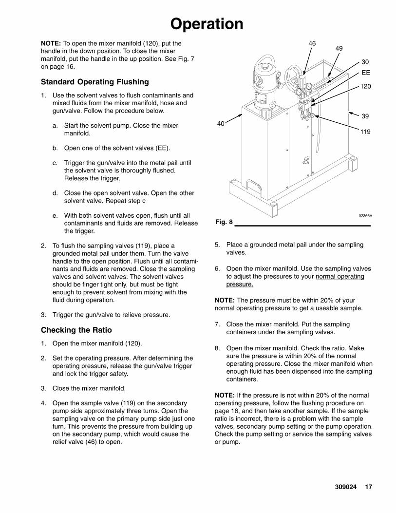
OperationNOTE: To open the mixer manifold (120), put thehandle in the down position. To close the mixermanifold, put the handle in the up position. See Fig. 7on page 16.
Standard Operating Flushing
1. Use the solvent valves to flush contaminants andmixed fluids from the mixer manifold, hose andgun/valve. Follow the procedure below.
a. Start the solvent pump. Close the mixermanifold.
b. Open one of the solvent valves (EE).
c. Trigger the gun/valve into the metal pail untilthe solvent valve is thoroughly flushed.Release the trigger.
d. Close the open solvent valve. Open the othersolvent valve. Repeat step c
e. With both solvent valves open, flush until allcontaminants and fluids are removed. Releasethe trigger.
2. To flush the sampling valves (119), place agrounded metal pail under them. Turn the valvehandle to the open position. Flush until all contami-nants and fluids are removed. Close the samplingvalves and solvent valves. The solvent valvesshould be finger tight only, but must be tightenough to prevent solvent from mixing with thefluid during operation.
3. Trigger the gun/valve to relieve pressure.
Checking the Ratio
1. Open the mixer manifold (120).
2. Set the operating pressure. After determining theoperating pressure, release the gun/valve triggerand lock the trigger safety.
3. Close the mixer manifold.
4. Open the sample valve (119) on the secondarypump side approximately three turns. Open thesampling valve on the primary pump side just oneturn. This prevents the pressure from building upon the secondary pump, which would cause therelief valve (46) to open.
Fig. 802366A
4039
4946
EE
30
119
120
5. Place a grounded metal pail under the samplingvalves.
6. Open the mixer manifold. Use the sampling valvesto adjust the pressures to your normal operatingpressure.
NOTE: The pressure must be within 20% of yournormal operating pressure to get a useable sample.
7. Close the mixer manifold. Put the samplingcontainers under the sampling valves.
8. Open the mixer manifold. Check the ratio. Makesure the pressure is within 20% of the normaloperating pressure. Close the mixer manifold whenenough fluid has been dispensed into the samplingcontainers.
NOTE: If the pressure is not within 20% of the normaloperating pressure, follow the flushing procedure onpage 16, and then take another sample. If the sampleratio is incorrect, there is a problem with the samplevalves, secondary pump setting or the pump operation.Check the pump setting or service the sampling valvesor pump.
18 309024
TroubleshootingTroubleshooting Techniques
Because the pumps are mechanically linked, the actionof one pump can affect the readings of the secondpump. Therefore, the key to successful troubleshootingis to be sure to isolate the problem.
For example, the secondary pump pressure, as readon the gauge, is low and sluggish during pumpchangeover. The most likely problem is a bindingprimary pump.
WARNINGTo reduce the risk of serious injury whenever youare instructed to relieve pressure, always follow thePressure Relief Procedure on page 15.
To isolate the pump:
1. Relieve the pressure.
2. Disconnect the index clamp (30) from thesecondary pump and lean the pump out of the wayof the lever arm (49). Now you can verify theoperation of the primary pump alone.
3. Use the sampling valves (119) at the mixermanifold (120).
a. Check the outlet ratio for the primary side.
b. With the sampling valves closed, check forpump stalling on both the up and downstrokes.
c. Check for rapid gauge response during pumpchangeover.
4. When the operation of the primary side has beenverified, reconnect the lever arm (49) to thesecondary pump. Let the primary pump run freelyin a pail of fluid and repeat the checks in Step 3 onthe secondary side.
WARNINGUse very low air pressure to the air motor whenmaking these checks. This system can producevery high fluid pressure, which can cause seriousinjury, including injection, splashing in the eyes oron the skin, and injury from moving parts. Followthe Pressure Relief Procedure on page 15.
WARNINGTo reduce the risk of injuring or amputating a hand,fingers or other body parts, never place your handsor any part of your body or any tools inside thesafety panel at any time, for any reason, while theunit is operating.
Refer to the manuals listed below to repairthe VRHC components.
Component Ref. No. Manual No.
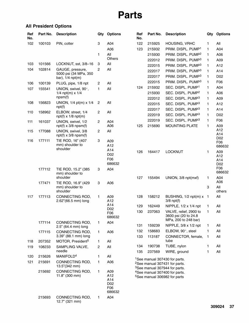
President Motor 207352 306982
Bulldog Motor 20835 307049
Monark Motor 205997 307043
Viscount IHydraulic Motor 948699 307654
Pump Lower 215932 307430
Pump Lower 215930 307431
Pump Lower 217339 307430
Pump Lower 222012 307944
Pump Lower 239388 307944
Pump Lower 222015 307944
Pump Lower 222017 307944
Pump Lower 222019 307944
Pump Lower 217529 306936
Pump Lower 901878 307862
Pump Lower 948640 684004
Pump Lower 948641 684004
Pump Lower 948195 307944
Pump Lower 948197 307944
309024 19
TroubleshootingProblem Cause Solution
System won’t run or stops whiler nning
Air pressure or volume too low Increase, check air compressor.running Closed or restricted air line or air
valveOpen or clean as required.
Fluid valves closed Open fluid valves.
Clogged fluid hose Replace fluid hose.
Air motor worn or damaged Service air motor; see manual306982.
Displacement pump stuck Service displacement pump. Seemanuals listed in the chart onpage 18.
Fluids not mixing properly Clogged filter in fluid line Clean; replace element if neces-sary.
Manifold problems Refer to manual 307400.
Check ratio Check; replace pump.
Clogged fluid hose Replace fluid hose.
System speeds up or runs erraticall
Fluid containers are empty Check often – keep filled.erratically Displacement pump parts worn or
damagedService displacement pump. Seemanuals listed in the chart below.
Squeaking or knocking noise isheard
Bearing(s) dry or worn Lubricate; replace bearing(s) ifnecessary.
Pump bottoming out See below.
System stops running on the endof a stroke
Secondary displacement pumpbottomed out because ratio indexclamp was set too far out
Adjust ratio index clamp.
Secondary displacement pumpbottomed out because top pivotbearings are set too high
Adjust bearings. See Removingthe Lever Arm from the VRHCFrame on page 21.
20 309024
ServiceRequired Service Tools
Tool Use for
3/32”–90� or T-handle hex key
All setscrews
3/4” open end wrench Clamp bolts and fluidhose on pump outlet
1” open end wrench Locknuts on capscrews
9/16” open end wrench Tie rod nuts
1/2” open end wrench Loosening tie rods frommotor base
1–1/8” open end wrench Pivot bearing locknuts
Adjustable open endwrench
Tightening connectingrod to pumps
Needle nose pliers Bending and pullingcotter pins
Medium slotted screwdriver
Removing shields
Small hammer and 6”punch
Tapping out pins
Bearing and Pump Lubrication
WARNINGTo reduce the risk of serious injury whenever youare instructed to relieve pressure, always follow thePressure Relief Procedure on page 15.
1. Relieve the pressure.
2. Insert one end of the nylon hose (52) into thewet-cup.
3. Pour Throat Seal Liquid (44) into the hose until thewet-cup is full.
4. Lubricate the VRHC periodically with Graco GearReducer Oil (43). If the pump is operating continu-ously at 60 cycles/min., lubricate at the pointsshown in Fig. 9 once every five days.
Service instructions are in the manuals for the sepa-rate components. See the chart on page 18.
Air Lubrication (Air Operated Motors Only)If your air supply is very dry, install air line lubricatorsbetween the air regulators and pumps for automatic airmotor lubrication. See Accessories in ConfiguratorProduct Order Form 309025 for a lubricator.
02371AFig. 9
11
1
1
1
Lubricate periodically with Graco Gear Reducer Oil
Detecting Bearing and Pin WearAudio DetectionWhen a bearing fails, it makes a knocking noise eachtime the pump changes stroke. Shut off the systemimmediately to avoid serious damage. Replace thebearing(s).
Visual DetectionCheck the movement of the lever arm (49) by watchingit through the opening in the safety panel (39). If itbounces, shut off the system immediately to avoidserious damage. Replace the bearing pin.
309024 21
ServiceRemoving the Lever Arm from the VRHCFrame
WARNINGTo reduce the risk of serious injury whenever youare instructed to relieve pressure, always follow thePressure Relief Procedure on page 15.
1. Flush the entire system with a solvent which iscompatible with the fluid being pumped. Discon-nect the air line and relieve the pressure.
2. Remove the safety panels (38,39,40). See Fig. 10.
3. Loosen the two setscrews (59) holding the primarydisplacement pump pin (35c) in the lever arm (49).See Fig. 11. The setscrews must be backed out farenough to clear the countersinks of the pin. Tapthe pump pin out of the lever arm and bearing.
4. Slide the primary pump out of the lever arm (49)slot and save the two nylon spacers (27c).
5. Slowly lower the pump to the floor until it supportsitself with the lower bearing (14d). See Fig. 17 onpage 27.
6. Push down on the secondary displacement pumpend of the lever arm (49) at point (JJ) until it is atthe bottom of the stroke. See Fig. 11.
7. Remove the two top capscrews (16a) from theindex clamp (30).
8. Raise the lever arm (49) slowly. Lower thesecondary pump to the floor until it supports itselfwith the lower bearing.
9. Loosen the two setscrews (17) located above theends of the frame pin (33). The setscrews must beturned out far enough to clear the countersinks ofthe pin.
10. Using a long punch and hammer, gently drive theframe pin (33) out from one end until it can bepulled out.
CAUTIONDo not drop the pin; dents will make reassembly diffi-cult.
11. Remove the punch and lift the lever arm (49) offthe VRHC frame.
12. Loosen the two pivot bearing locknuts (2) and turnthe bearings (15) out of the housing (122). Thebearings should be only hand tight. If they aretighter, use a wrench on the flats of the bearing(15) to unscrew the bearing from the frame.
Fig. 10
49
39
112
381
40
02366A
Fig. 11
59121
33
35c
27c2
15
34a
17
49
31
16a30
JJ
02372
22 309024
ServiceDetermining Which Pin and/or Bearing isWorn1. Disassemble the VRHC. After the pins and bear-
ings are removed, wipe them off with a clean rag.
2. Visually inspect the pins for scoring, lines, groovesand scratches on the area in contact with thebearing. Then feel the surface of the pin for roughareas or a difference in size. If these signs of wearare detected, replace both the pin and bearing.
3. To check the bearings, hold the threaded part ofthe bearing in one hand and use the other hand tomove the balls inside the bearing up and down. Ifthere is any noticeable movement, replace thebearings. Also check the bearings for roundness. Ifa bearing appears to be out of round (egg-shaped), replace it.
Fitting the Pins into the BearingsTolerances between the surface of the pin and thebearings are very close. Never force the pin into thebearing. If the pin does not fit, sand it from the end tojust past the countersinks with 500 grit sandpaper. SeeFig. 12. If the pin still does not fit, return it to thefactory for replacement. If the pin needs replacement,replace the bearing also.
02373Fig. 12
Storage of Spare Pins and BearingsCompletely coat spare pins and bearings with GracoGear Reducer Oil (43) or the equivalent when storingthese parts. Never use grease.
Removing the Secondary Pump and/or theBearings and Pins
1. Flush the entire system with a compatible solvent.
WARNINGTo reduce the risk of serious injury whenever youare instructed to relieve pressure, always follow thePressure Relief Procedure on page 15.
2. Relieve the pressure.
3. Remove the safety panel (39). See Fig. 13.Disconnect the inlet and outlet fluid hoses of thesecondary displacement pump (124).
Fig. 1302366A
1
39
Continued on page 23.
309024 23
ServiceNOTE: Refer to Fig. 14 for steps 4 to 10.
4. Push down on the lever arm (49) until the wrenchflats (KK) on the secondary pump (124) are justabove the wet-cup (LL). Remove the ratio indexclamp capscrews (16a) and the index clamp (30).
NOTE: Some fluid will drip from the pump when youare removing the ratio index clamp.
5. Raise the lever arm (49) off the pivot pin support (31a).
6. Remove the connecting rod cotter pin (102), if thepump has one. Unscrew the connecting rodassembly (117, 14a, 34a, 31a) in one piece fromthe pump.
7. If you are removing only the pump, remove it fromthe inlet manifold (32). If the secondary pump(s)need repair, follow the instructions in its manual.
8. If you are removing the bearings and pins, tilt thesecondary pump (124) forward until it rests on thefloor. Then follow Steps 9 and/or 10.
9. If you are removing the upper bearing (14a) andsupport pin:
a. Loosen the two setscrews (17a). Back out thesetscrews far enough to clear the countersinksof the support pin (34a).
b. Place the support (31a) in a vise. Unscrew theconnecting rod (117) from the bearing (14a).The connecting rod and bearing are sealedwith thread sealant and may be difficult tounscrew.
c. Remove the support (31a) from the vise.Gently tap the support pin (34a) out with ahammer and punch.
d. Replace the support pin and bearing.
10. If removing the lower bearing (14b) and support pin (34b):
a. Remove one of the lower clamps (28) andcapscrews (16b).
b. Loosen the locknut (3) and screw the pumpmanifold (32) off the bearing (14b) to removethe secondary displacement pump (124).
c. Remove the remaining clamp (28) and cap-screw (16b) from the lower support (31b).
d. Raise the VRHC lower frame (50) and removethe support (31b).
e. Gently tap the support pin (34b) out with ahammer and punch.
f. Replace the pin and bearing.
Fig. 14
02374
16a 30
49
17a
31a
34a
117
102
KKLL
124
32
16b
28
50
3
14b
31b
34b
17b
14a
24 309024
ServiceReplacing the Secondary Pump and/or theBearings and Pins
NOTE: Refer to Fig. 14 for Steps 1 to 3.
1. If only the secondary pump is being replaced:
a. Screw the secondary pump (124) into the inletmanifold (32). The manifold must face the endof the VRHC as shown in Fig. 14. If it doesnot, rotate the secondary displacement pumpuntil it does, and tighten the locknut (3) againstthe inlet manifold. Torque the locknut to 60 ft-lb(81 N.m).
b. Replace the connecting rod assembly (117,14a, 34a, 31a) onto the displacement rod, andline up the cotter pin holes. Insert the cotterpin (102).
c. Raise the lever arm (49) and place the support (31a) under the proper slot.
d. Push down the lever arm until the support fitsinto the slot. If the support does not line upwith the slot, rotate it clockwise until it does.
e. Place the ratio index clamp (30) over the top ofthe support (31a). Insert the capscrews (16a).
f. Set the index clamp (30) for the proper ratioand tighten the capscrews (16a).
2. If replacing the lower bearing (14b) and support pin (34b):
a. Place a generous amount of Graco GearReducer Oil (43) on the inside of the lowerbearing (14b) and the surface of the supportpin (34b).
b. Screw the locknut (3) onto the bearing (14b)threads until the locknut bottoms out.
c. Slide the bearing into the slot in the support (31b). Insert the pin (34b) into placewith the countersinks under the setscrew (17)holes. Tighten the setscrews to 35 in-lb (4N.m). These are 10–32 self-locking setscrews.If no drag is felt while turning, replace thesetscrew.
d. Screw the secondary displacement pump (124) and manifold (32) onto the bearing (14b) until it bottoms out. Be sure it isnot resting against the locknut (3).
e. Align and loosely install the two clamps (28)and capscrews (16b).
3. If replacing the upper bearing (14a) and supportpin (34a):
a. Place a generous amount of Graco GearReducer Oil (43) on the inside of the upperbearing (14a) and the surface of the supportpin (34a).
b. Slide the support (31a) onto the bearing (14a).Insert the support pin (34a) with the counter-sinks in place under the setscrew (17a) holes.
CAUTIONDo not force the pin into place. Check for burrs onthe pin or in the VRHC frame if the pin does not slideinto place.
c. Tighten the setscrews (17a) to 35 in-lb (4 N.m). These are 10–32 self-locking screws.If no drag is felt while turning, replace thesetscrews.
d. Place the support (31a) in a vise and screwthe connecting rod (117) onto the bearing(14a). The connecting rod and the bearing canbe disassembled and then reused one timebefore needing replacement. Be sure to sealthe connecting rod and the bearing with threadsealant such as Loctite� No. 27105 or theequivalent. Apply 3 drops of the sealant to thethreads of the bearing.
e. Screw the connecting rod (117) onto the pump (124) until the cotter pin holes line up (ifthe displacement pump has them). Install thecotter pin (102) and tighten the connecting rodagainst the piston shoulder of the displace-ment rod.
f. Follow steps 1.c to 1.f at left.
g. Tighten the capscrews (16b) at the bottom ofthe secondary displacement pump (124).
309024 25
ServiceRemoving the Primary Pump and/or theLower Bearing and Pin1. Flush the entire system with a compatible solvent.
WARNINGTo reduce the risk of serious injury whenever youare instructed to relieve pressure, always follow thePressure Relief Procedure on page 15.
2. Relieve the pressure.
3. Remove the safety panels (39,40). Disconnect theinlet and outlet hoses on the primary displacementpump (123).
NOTE: Refer to Fig. 15 for Steps 4 to 6.
4. Remove the three tie rod locknuts (103) and pushup on the air motor (118) until the tie rods (116)clear the mounting holes of the displacementpump. See Fig. 15.
5. Using a wrench on the flats of the tie rods,unscrew them from the air motor base.
6. Remove the upper cotter pin (102c) and unscrewthe air motor from the connecting rod (121).
02375AFig. 15
103
116
118
102c
121
Continued on page 26.
26 309024
ServiceNOTE: If only the motor needs repair, follow theinstructions in the appropriate manual.
NOTE: Refer to Fig. 16 for Steps 7 to 15.
7. Remove the lower cotter pin (102d) from theconnecting rod (121) (if the pump has one) andloosen the two setscrews (59). The setscrewsmust be backed out far enough to clear the coun-tersink of the bearing support pin (35c).
8. Hold the connecting rod (121) and gently tap outthe support pin (35c) with a hammer and punch.
9. Slowly pull the connecting rod (121) away from thelever arm (49) and tilt the pump (123) forward untilit rests on the frame. Save the two nylon spacers (27c).
10. Unscrew the connecting rod (121) from thedisplacement pump (123). If necessary, replacethe connecting rod.
11. If removing the pump only, remove it from themanifold (32). If the primary pump needs repair,follow the instructions in the separate pumpmanual.
12. If removing the lower bearing (14d) and pin (35d),tilt the primary pump (123) forward until it rests onthe floor. Then follow steps 13 to 15.
13. Loosen the lower rod end locknut (3) and unscrewthe pump manifold (32) to remove the primarypump (123).
14. Loosen the two setscrews (17b). The setscrewsmust be backed out far enough to clear the coun-tersinks of the support pin (35d).
15. Remove the pin (35d) and save the two nylonspacers (27d) and the bearing (14d).
02375A
Fig. 16
02377
02376
103
116
118
102c
121
123
102d
59
35c27c
12149
32
314d
27d35d
17b
309024 27
ServiceReplacing the Primary Pump and/orBearing and Pins
NOTE: Refer to Fig. 17 for Steps 1 to 9 except wherenoted.
1. Screw the displacement pump (123) into the inletmanifold (32) so the outlet is facing the back.
2. Screw the connecting rod (121) onto the primarydisplacement pump until the cotter pin holes lineup. Install the cotter pin (102d) if the pump hasone; if not, bottom out the connecting rod on thedisplacement pump.
3. Pull the connecting rod upward until the displace-ment pump stops.
4. Screw the air motor (118) onto the connecting roduntil the cotter pin holes line up. Install the cotterpin (102c).
5. Rotate the air motor until the air inlet port is on thesame side as the air inlet manifold (37).
6. Screw the three tie rods (116) into the air motorbase and torque to 35–50 ft-lb (47–68 N.m).
NOTE: One of the tie rods will run through the leverarm slot.
7. Push down the air motor and place the tie rods intothe displacement pump tie plate. Tighten the tierod locknuts (103).
8. To install the support pin (35c) into the upperbearing:
a. Remove the two capscrews (16a) from thesupport (31a) on the secondary pump (124).
b. Move the lever arm (49) until you can placethe nylon spacers (27c) and support pin (35c)in line with the bearing in the connecting rod(121).
c. Lubricate the support pin with Gear ReducerOil (43) and tap it into the upper bearing withthe countersinks facing up.
CAUTIONDo not force the pin into place. Check for burrs onthe pin or in the VRHC frame if the pin does not slideinto place. Sand with 500 grit sandpaper between thecountersinks.
d. Torque the two setscrews (59) to 35 in-lb (4 N.m). See Fig. 18 on page 29.
e. Move the lever arm (49) back into place andreinstall the two capscrews (16a) onto thesupport (31a) of the secondary pump.
02375AFig. 17
1
2
118
59
27c
116
103
32
102d
35c
49
102c121
123
35d
3
14d
27d
17b
1
2
Torque to 60 ft-lb (81 N.m)
Torque to 35 in-lb (4 N.m)
02430
28 309024
Service9. If replacing the lower bearing (14d) and pin (35d):
a. Thread the locknut (3) all the way onto thebearing.
b. Screw the inlet manifold (32) onto the bearingtwelve turns and tighten the locknut up to theinlet manifold. Torque to 60 ft-lb (81 N.m).
c. Lubricate the support pin (35d) with GearReducer Oil (43). Install the pin with the coun-tersinks facing up, into one side of the framebase (50). Place one nylon spacer (27d) onthe end of the support pin.
d. Install the bearing (14d) and manifold (32) andalign them with the support pin (35d).
e. Tap the pin in flush with the opposite side ofthe frame. Align the second nylon spacer withthe support pin, and tap the pin all the way intothe side of the frame base (50).
f. Tighten the two setscrews (17b) onto thesupport pin (35d). Torque to 35 in-lb (4 N.m).
g. Follow the procedure for replacing the primarypump on page 27.
Replacing the Lever Arm on the Frame
CAUTIONTolerances between the surface of the frame andbearing are very close. Do not force the pin intoplace. Check for burrs on the pin or in the VRHCframe if the pin does not slide into place. Sand with500 grit sandpaper between the countersinks.
NOTE: Refer to Fig. 18 for Steps 1 to 5.
1. Screw the locknuts (2) onto the pivot bearing (15).
2. Screw the pivot bearing into the frame base (50).Adjust the distance from the top of the support pin (33) to the bottom of the frame (50) to 26.125”(664 mm).
3. With the bearings at the correct height and parallelto each other, torque the locknuts (2) to 60 ft-lb (81 N.m).
4. Place a generous amount of lubricant (43) onto thesupport pin, and place the lever arm (49) over thebearings (15).
5. Slide the support pin, with the countersinks up,through the lever arm and bearings. Torque thetwo setscrews (17) to 35 in–lb (4 N.m).
NOTE: If no drag is felt while turning the setscrews,replace them.
222012 222015 1.2:1 to 5.6:1 1.10 to 0.70(4.2 to 2.6)
1300 to 2200(9 to 15, 90 to 152)
222012 222017 1.4:1 to 6.7:1 1.10 to 0.70(4.2 to 2.6)
1400 to 2200(9.7 to 15, 97 to 152)
222012 222019 1.9:1 to 9.0:1 1.10 to 0.70(4.2 to 2.6)
1600 to 2300(11 to 16, 110 to 159)
�Maximum to minimum ranges.NOTE: Output pressure decreases as volume output increases.�Based on pump speed of 40 cycles per minute using No. 10 oil test media.
Wetted Parts – See Configurator Product Order Form 309025
Pump ModelMaximum Fluid Working Pressure Maximum Pump Air Input Pres-
sure
President� 250 bar, 25.0 MPa (3600 psi) 12.5 bar, 1.25 MPa (180 psi)
Monark� 125 bar, 12.5 MPa (1800 psi) 12.5 bar, 1.25 MPa (180 psi)
Bulldog� 347 bar, 34.7 MPa (4950 psi) 6.3 bar, 0.63 MPa (90 psi)
Pump ModelAir Pressure of Sound Tests(25 cycles/min)
* Sound PressureLevel
** Sound Power Level
President� 12.5 bar, 1.25 MPa (180 psi)
98 dBa 113 dBa
Monark� 12.5 bar, 1.25 MPa (180 psi)
96 dBa 112 dBa
Bulldog� 7 bar, 0.7 MPa (100 psi)
94 dBa 109 dBa
* Sound pressure was measured in accordance with Cagi Pneurop, 1969. ** Sound power was measured in accordance with ISO 3744, 1981.
40 309024
Graco Standard WarrantyGraco warrants all equipment manufactured by Graco and bearing its name to be free from defects in material and workmanship on thedate of sale by an authorized Graco distributor to the original purchaser for use. With the exception of any special, extended, or limitedwarranty published by Graco, Graco will, for a period of twelve months from the date of sale, repair or replace any part of the equipmentdetermined by Graco to be defective. This warranty applies only when the equipment is installed, operated and maintained in accor-dance with Graco’s written recommendations.
This warranty does not cover, and Graco shall not be liable for general wear and tear, or any malfunction, damage or wear caused byfaulty installation, misapplication, abrasion, corrosion, inadequate or improper maintenance, negligence, accident, tampering, or sub-stitution of non–Graco component parts. Nor shall Graco be liable for malfunction, damage or wear caused by the incompatibility ofGraco equipment with structures, accessories, equipment or materials not supplied by Graco, or the improper design, manufacture,installation, operation or maintenance of structures, accessories, equipment or materials not supplied by Graco.
This warranty is conditioned upon the prepaid return of the equipment claimed to be defective to an authorized Graco distributor forverification of the claimed defect. If the claimed defect is verified, Graco will repair or replace free of charge any defective parts. Theequipment will be returned to the original purchaser transportation prepaid. If inspection of the equipment does not disclose any defectin material or workmanship, repairs will be made at a reasonable charge, which charges may include the costs of parts, labor, andtransportation.
THIS WARRANTY IS EXCLUSIVE, AND IS IN LIEU OF ANY OTHER WARRANTIES, EXPRESS OR IMPLIED, INCLUDING BUTNOT LIMITED TO WARRANTY OF MERCHANTABILITY OR WARRANTY OF FITNESS FOR A PARTICULAR PURPOSE.
Graco’s sole obligation and buyer’s sole remedy for any breach of warranty shall be as set forth above. The buyer agrees that no otherremedy (including, but not limited to, incidental or consequential damages for lost profits, lost sales, injury to person or property, or anyother incidental or consequential loss) shall be available. Any action for breach of warranty must be brought within two (2) years of thedate of sale.
Graco makes no warranty, and disclaims all implied warranties of merchantability and fitness for a particular purpose in connectionwith accessories, equipment, materials or components sold but not manufactured by Graco. These items sold, but not manufacturedby Graco (such as electric motors, switches, hose, etc.), are subject to the warranty, if any, of their manufacturer. Graco will providepurchaser with reasonable assistance in making any claim for breach of these warranties.
In no event will Graco be liable for indirect, incidental, special or consequential damages resulting from Graco supplying equipmenthereunder, or the furnishing, performance, or use of any products or other goods sold hereto, whether due to a breach of contract,breach of warranty, the negligence of Graco, or otherwise.
FOR GRACO CANADA CUSTOMERSThe parties acknowledge that they have required that the present document, as well as all documents, notices and legal proceedingsentered into, given or instituted pursuant hereto or relating directly or indirectly hereto, be drawn up in English. Les parties reconnais-sent avoir convenu que la rédaction du présente document sera en Anglais, ainsi que tous documents, avis et procédures judiciairesexécutés, donnés ou intentés à la suite de ou en rapport, directement ou indirectement, avec les procedures concernées.
Graco InformationTO PLACE AN ORDER, contact your Graco distributor, or call one of the following numbers
to identify the distributor closest to you: 1–800–328–0211 Toll Free
612–623–6921612–378–3505 Fax
All written and visual data contained in this document reflects the latest product information available at the time of publication.Graco reserves the right to make changes at any time without notice.
MM 309024
Graco Headquarters: MinneapolisInternational Offices: Belgium, China, Japan, Korea
GRACO INC. P.O. BOX 1441 MINNEAPOLIS, MN 55440–1441www.graco.com