3- : 3 3 Within the general scope of the B30 Standard, as
defined in Section I of the B30 Standard Introduction, the B30.3 Volume applies to “construction tower cranes” and “permanently mounted tower cranes” that are powered by electric motors or internal combustion engines and that adjust their operating radius by means of a luffing boom mechanism, a trolley traversing a horizontal jib, or a combination of the two. The cranes may be mounted on “fixed bases” or “traveling bases” and may have tower and supporting structure arrangements that permit the crane to climb in a structure being built or that permits increasing the crane’s tower height as the structure rises. Variations of the above physical characteristics that provide the same fundamental operating characteristics are included in the scope of this Volume; however, the requirements of this Volume are only applicable to the cranes within this scope when they are used in lifting operations. Mobile cranes configured with tower attachments (refer to ASME B30.5) and self-erecting tower cranes (refer to ASME B30.29) are not within the scope of this Volume.
a er 3-re o a D sma l g
ara er s s a o s ru o
3- : Preoperation tests shall be performed after a crane
is erected, climbed, altered, or modified and before the crane is placed into service. During preoperation tests, if any indication of unsatisfactory performance of any function is observed, further testing shall be discon-tinued until a qualified person has determined that the crane performance and condition are satisfactory for continued testing. If load testing is required, the load shall be freely suspended.
(a) After a crane is erected and before being placed into service, the following is required:
(1) Functional motions, motion limiting devic-es, and brakes shall be tested for satisfactory operation. (2) Functional motion tests made after erection shall be performed in the following order: (a) functional motion tests without load (b) functional motion tests at rated load [for other-than traveling cranes, this may be combined with tests of supports per para. 3-1.7(b)] (b) The structural supports or foundation to which the crane base is attached shall be tested. If any part of the support structure becomes displaced or distressed during testing, all crane operations shall stop- until an evaluation is made by a qualified person. (1) For static mounted cranes, the test shall be conducted with a rated load along the curve , placed at the maximum radius permitted by site limitations, and the crane rotated slowly through 360 deg. If site condi-tions do not permit 360 deg rotation with load, those portions of the test shall be performed with no load (luffing boom cranes with luffing boom at minimum radius). (2) For traveling cranes, load tests shall be conducted with the jib, luffing boom, or counterjib in the position creating the maximum loading on a single wheel or bogie. The test shall comprise traveling the entire length of the runway so as to test each rail with a single wheel or bogie under maximum load. If any runway support becomes displaced or damaged, crane operations shall stop until a qualified person determines that the condition or repair is satisfactory before proceeding (3) The testing shall continue until all controls, drives, and braking means have been verified as having functioned correctly. Devices tested shall include (a) load block hoisting and lowering (b) luffing boom hoisting and lowering, or trolley traversing (c) swinging of the upper structure (d) brake and clutch functioning (e) limit, locking, and safety device functioning (f) load-limiting devices to verify proper setting and operation
Hooks shall be removed from service is damage such as the following is visible and shall only be returned to service when approved by a qualified person:
(d) cracks, nicks or gouges(e) wear. Any wear exceeding 10% (or as recommended
by the manufacturer) of the original section dimension of the hook or its load pin.
(f) deformation. Any visibly apparent bend or twist from the plane of the hook or its load pin.
(g) throat opening. Any distortion causing an increase in throat opening exceeding 5%, not to exceed 1/4 inch (6mm) (or as recommended by the manufacturer).
(h) inability to lock. Any self-locking hook that does not lock.
(i) inability to latch (if required). Any damaged latch or malfunctioning latch that does not close the hood’s throat.
(4) After a crane is climbed and before being placed into service, the following is required:
(a) Functional motions, motion limiting devices, and brakes shall be tested for satisfactory operation
(b) Functional motion tests made after climb-ing shall be performed without load.
(c) Testing shall verify that all controls, drives, and braking means function correctly. Devices tested shall include
(1) load block hoisting and lowering(2) luffing boom hoisting and lowering,
or trolley traversing(3) swinging of the upper structure(4) brake and clutch functioning(5) limit, locking and safety device
functioning(6) load-limiting devices to verify their
proper operation(5) The structural supports to which the crane is
attached shall be tested. If any part of the support struc-ture becomes displaced or distressed during testing, all crane operations shall stop until an evaluation is mead by a qualified person. The test shall be conducted with a rated load along the load curve, placed at the maximum radius permitted by site conditions, and the crane rotated slowly through 360 deg. If site conditions do not permit a 360 deg rotation with load, those portions of the test shall be performed with no load and the counterjib over the side being tested (luffing boom crane with luffing boom at minimum radius).
3- : L D a L
3- 4 ea es(a) Sheave grooves shall be free from surface
conditions that could cause rope damage. The cross-sectional radius at the bottom of the groove should be such as to form a close fitting saddle for the size of rope used. The sides of the groove shall be tapered outward and rounded at the rim to facilitate entrance of the rope into the groove. Flange rims shall run true about the axis of rotation.
(b) Sheaves carrying ropes that can become mo-mentarily unloaded shall be provided with close-fit-ting guards or other devices to guide the rope back into the groove when the load is reapplied.
3- : (d) Wire rope clips, wedge sockets, and compres-sion hardware shall be installed in accordance with ASME B30.26, Section 26-3.1.
3- 3: 3- 3 4 re gu s er A portable fire extinguisher, with a basic mini-mum extinguisher classification of 10-ABC, shall be installed in the cab or at the machinery housing.
3- : 3- e eral(a) Where inspection criteria provided by the manu-
facturer differ from the information provide in this Sec-tion, the manufacturer’s criteria shall take precedence.
(b) Inspections shall be performed by a designated person. Any deficiencies identified shall be examined and a determination made by a qualified person as to whether they constitute a hazard.
3- s e o lass fi a o(a) Initial Inspection. Tower cranes shall undergo
a Periodic and Major Inspection...(b) ...These regular inspection classifications are
designated as Frequent Inspection, Periodic Inspection and Major Inspection, and their respective occurrence intervals are defined below.
(2) Periodic Inspections shall be conducted an-nually, or at intervals recommended by the manufac-turer or by a qualified person.
(3) Major Inspections shall be conducted at 60-mo intervals, or as recommended by the manufacturer or by a qualified person.
3- 4 er o s e o(a) Items and conditions such as those listed shall
be inspected at the intervals defined in para. 3-2.1.2(b)(2) or as specifically indicated for an item or condition. Observations during operation shall be used to identify deficiencies that might appear between inspections. Deficiencies determined to constitute a hazard shall be corrected before the crane is placed back into service. Records shall be kept of the inspected items and condi-tions to provide a basis for continuing evaluation. In-spect
(1) items and conditions contained in para. 3-2.1.3.
(2) deformed, cracked, or corroded members in the crane structure or crane support systems. If in-dications of possible damage are observed, the need to removed paint or to use a higher level of nondestruc-tive examination technique, to determine if a hazard exists, shall be made by a qualified person. (3) damaged sheaves and drums in all rope systems. (4) loose, worn, cracked, or distorted parts, such as bolts, pins, bearings, shafts, gears, rollers, locking and clamping devices, sprockets, and drive chains or belts. (5) brake and clutch system parts, linings, pawls, and ratchets for wear that exceeds the manu-facturer’s allowable tolerances. (6) load, wind, radius, and other indicators for inaccuracies outside the tolerances recommended by the manufacturer. (7) electrical systems for deterioration in con-trollers, master switches, contact, components, wires, cables, and controls. (8) load hoist, luffing, trolley, swing, and trav-el mechanisms for malfunction, wear, or damage. (9) pumps, motors, valves, hoses, fittings, and tubing for wear or damage (10) wire rope as required in Section 3-2.4. (11) walkways, ladders, and access systems for deficiencies. (12) guarding for missing or damaged components. (13) electrical grounding of crane structure for missing or improper connections. (b) Cranes that have been idle for a period of 1 mo or more shall be inspected in accordance with (a) above before being placed back into service. (c) For cranes with 5 or more years of service, in-spections performed in accordance with (a) above are recommended at more frequent intervals, unless the manufacturer recommended other intervals.
3- a or s e o(a) Items and conditions such as those listed shall
be inspected at the intervals defined in para. 3-2.1.2(b)(3) or as specifically indicated for an item or condi-tion. In addition to those items listed, the manufac-turer’s inspection and maintenance requirements shall be accomplished. Observations made during operation shall be used to identify deficiencies that might appear between inspections. Deficiencies determined to con-stitute a hazard shall be corrected before the crane is placed back into service. Records shall be kept of the inspected items and conditions to provide a basis for continuing evaluation. Inspect
(1) Inspect items and conditions contained in paras. 3-2.1.3 and 3-2.1.4.
(2) Verify completion of any safety upgrades recommended by the crane manufacturer.
(3) Verify presence of the most recent applicable documentation published by the crane manufacturer. (4) Verify proper operation of fluid system re-liefs and accumulator conditions. (5) Consideration should be given to nonde-structive testing of all tower and slewing ring connec-tion material, or replacement in accordance with the manufacturer’s instructions.
(6) Inspect for deformed, cracked, or corroded members in the crane structure. If indications of pos-sible damage are observed, a higher level of nonde-structive examination or the removal of paint shall be performed to determine if a hazard exists.
(7) Disassemble and inspect drive systems, motors, and gear boxes in accordance with the manu-facturer’s frequency requirements.
(8) Inspect and test all electrical components, including wiring, drives, controls, and connections. (9) Inspect sheaves, including bearings and corrugation. (10) Inspect the slewing ring, including disas-sembly as required in accordance with the manufactur-er’s requirements for inspection, cleaning, and servicing.
(b) For permanently mounted tower cranes with 10 or more years of service, the inspection specified in (a) above shall be performed at annual intervals. Dis-assembly requirements under (a)(7) and (10) are only required when specified by the manufacturer.
3- : 3- era o al es s (a) Each time a crane is erected or reconfigured, prior to initial use it shall be tested in accordance with para. 3-1.7. (b) After a repair, cranes shall be tested if a quali-fied person determines that testing is required prior to returning the crane to service. If a load test is required, it shall be in accordance with Section 3-1.7. (c) A record of the operational tests when a crane is erected, reconfigured, or repaired shall be complet-ed and retained until a subsequent test is completed. At a minimum the record shall indicate test dates, tests performed, and results obtained.
3- era o al es ro e ures or ra e L m De es The actuating settings of limit devices shall be de-termined by the following tests: (a) The hoist limit (anti two-block) shall be tested with an empty hook and be comprised of a series of runs, each at increasing hook speeds, up to the maxi-mum speed. The actuating mechanism of the decelera-tion and limit device shall be adjusted so that it will prevent two-blocking. (b) The trolley travel limit device settings shall be verified by means of a static test using loads of 102.5% to 110% of the applicable ratings as recommended by the crane manufacturer. Test loads are to be lifted at creep speed until just clear of the ground. (c) Load limit device settings shall be verified by means of a load test using freely suspended loads, as specified by the crane manufacturer or, in the absence thereof, the instructions of a qualified person...
- : 3 Volume B30.29 includes provisions that apply to
the construction, operation, inspection, testing, and maintenance of powered self-erect tower cranes that adjust operating radius by means of a trolley traversing a jib. These may be horizontal, elevated, articulating, or telescoping, and used for vertical lifting an lowering of freely suspended, unguided loads that consist of equipment and materials.
Self-erect tower cranes have vertical or nearly vertical masts that are bottom slewing and mounted on fixed, traveling, or mobile bases. The cranes are capable of moving or being moved from jobsite to jobsite fully assembled or nearly fully assembled.
This Volume does not apply to cranes used for nonvertical lifting service or lifting a guided load, or to truck-mounted material delivery cranes with a tubular boom and trolley traversing the boom. Tower cranes (refer to ASME B30.3) and mobile crane tower attachments (refer to ASME B30.5) are not within the scope of this Volume.
a er -e eral o s ru o a s alla o
- : D
- 3 era o al es sOperational tests are intended to verify that the crane
can satisfactorily perform its intended functions and is in compliance with the manufacturer’s specifications. If indications of unsatisfactory performance of any function are observed, further testing shall be discontinued until a qualified person has verified that the crane performance and condition are satisfactory.
(a) When cranes are erected and after each reconfiguration, before placing the crane in service, all functional motions, motion-limiting devices, brakes, and indicating devices shall be tested for proper operation.
(b) The order in which tests of a newly erected or reconfigured crane are to be performed is as follows:
(1) Functional Motion Tests Without Load. Each test shall include
(a) hoisting and lowering(b) traversing the trolley(c) swing motion(d) brakes and clutches(e) operational aids and motion-limiting
devices(2) Functional Load Tests at Rated Load. Each
test shall include(a) load hoisting and lowering(b) traversing the trolley(c) swing motion(d) brakes and clutches(e) operational aids and load-limiting
devicesDuring testing, the crane supports shall be checked.
Any observed displacement is reason to suspend testing until an evaluation is made by a qualified person.
(3) For cranes mounted on engineered structural supports, the test shall be conducted as follows:
(a) A test shall be conducted with the maximum moment load placed at maximum radius permitted by site limitations. The superstructure shall be rotated through 360 deg or maximum degrees of rotation permitted by site limitations, with 5-min stops at each outrigger position or as close to each outrigger position as site limitations permit. If any part of the support structure becomes displaced or distressed, all crane operations shall stop until an evaluation is made by a qualified person.
(b) For rail-mounted cranes, a load test shall be conducted with the jib in the position causing maximum loading on one wheel or bogie. The test shall comprise traveling the entire length of the runway then returning with the same load on the other rail. If a sleeper or support becomes displaced or damaged, crane operations shall stop until an evaluation is made by a qualified person. Where traveling with a load is not permitted by the manufacturer, the load test shall be conducted with the superstructure positioned to create maximum loading on one wheel or bogie.
- 3: L- 3 3 u r ggers
(a) The manufacturer’s documentation for the crane shall describe the use of outriggers and wheth-er they are required for in-service, out-of-service, or backward stability.
(b) Means shall be provided to hold all outriggers in the retracted position while traveling, and in the ex-tended position when set for operating.
(c) Power-actuated jacks, where used, shall be pro-vided with the means (such as integral load hold check valves on hydraulic cylinders, mechanical locks, etc.) to prevent uncontrolled cylinder movement.
(d) Means shall be provided for fastening outrigger floats to outriggers when in use.
- : L - e eral e u reme s
(a) Rail-mounted cranes shall be equipped with means to prevent running into the buffers or stops while under power.
(b) Drives shall be capable of smooth starts and stops, and provide varying degrees of acceleration and deceleration.
(c) An audible signal shall automatically sound whenever the crane travels in order to warn persons in the vicinity.
3 l able ems o o ere b ub ar
- og es(a) Bogies shall be fitted with sweeps extending
below the top of the rail and placed in front of the lead-ing wheel in either direction unless the construction of the rail foundation prohibits such extension. (b) Bogie wheels shall be guarded. (c) Means shall be provided to limit the drop of bogie frames to a distance that will not cause the crane to overturn in case of wheel or axle breakage.
a er -s e o es g a a e a e
- : - era o al es s
Cranes shall be tested in accordance with para. 29-1.1.3. Altered or modified cranes shall be tested under the direction of a qualified person to verify compliance with the applicable portions of this Volume, including functional tests in accordance with para. 29-1.1.3.
- Loa L m De e esLoad limit device settings shall be verified by using
freely suspended test loads of known weight sufficient to activate the load limit device.
- 3 es e or sDated records shall be made for all tests required
under paras. 29-2.2.1 and 29-2.2.2. The most current test record shall be maintained.
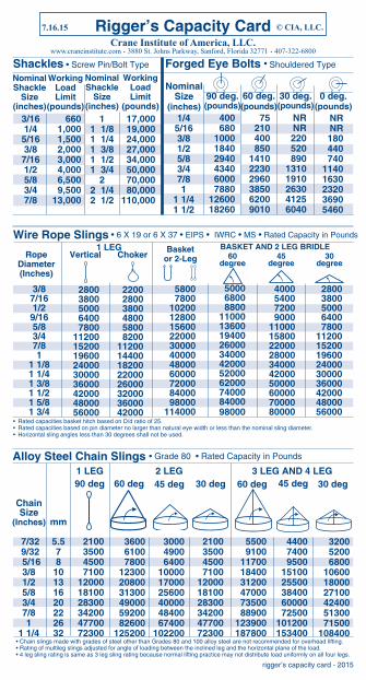
• Rated capacities basket hitch based on D/d ratio of 25.• Rated capacities based on pin diameter no larger than natural eye width or less than the nominal sling diameter.• Horizontal sling angles less than 30 degrees shall not be used.
• Chain slings made with grades of steel other than Grades 80 and 100 alloy steel are not recommended for overhead lifting.• Rating of multileg slings adjusted for angle of loading between the inclined leg and the horizontal plane of the load.• 4 leg sling rating is same as 3 leg sling rating because normal lifting practice may not distribute load uniformly on all four legs.
Calculating Load Weight • Weights of Materials & Liquids - lb per cubic ft
• When sling angles are between those listed in chart, use the next lower sling angle and corresponding load angle factor.• When using 3 or 4 sling legs equal in length, divide the total load by 3.• When the load is not distributed uniformly (equally) on sling legs, the tension on each leg must be calculated individually.
• Horizontal sling angles less than 30 degrees shall not be used.• For choker hitch, the angle of choke shall be 120 degrees or greater (see ASME B30.9)
3. Multiply load weight by Load Angle Factor to get total load on sling Legs. ( 2000 lbs x 1.414 = 2828 lbs )4. Divide total load by the number of sling legs. (2828 lbs ÷ 2 = 1414 lbs per sling leg)
5. Select slings from the single vertical leg column within the sling capacity table.