334129K EN Instructions-Parts Therm-O-Flow ® 20 For applying hot melt sealant and adhesive materials from 20 Liter (5 Gallon) pails. For professional use only. Not approved for use in European explosive atmosphere locations. Maximum Operating Temperature 400°F (204°C) See page 6 for model information. See Technical Specifications, page 106, for maximum working pressures. Important Safety Instructions Read all warnings and instructions in this manual and in related manuals. Save these instructions. 3143485
Transcript
334129KEN
Instructions-Parts
Therm-O-Flow® 20For applying hot melt sealant and adhesive materials from 20 Liter (5 Gallon) pails. For professional use only.
Not approved for use in European explosive atmosphere locations.
Maximum Operating Temperature 400°F (204°C)See page 6 for model information.
See Technical Specifications, page 106, for maximumworking pressures.
Important Safety InstructionsRead all warnings and instructions in this manual and in related manuals. Save these instructions.
WarningsThe following warnings are for the setup, use, grounding, maintenance, and repair of this equipment. The exclama-tion point symbol alerts you to a general warning and the hazard symbols refer to procedure-specific risks. When these symbols appear in the body of this manual or on warning labels, refer back to these Warnings. Product-specific hazard symbols and warnings not covered in this section may appear throughout the body of this manual where applicable.
WARNINGBURN HAZARD
Equipment surfaces and fluid that is heated can become very hot during operation. To avoid severe burns:
• Do not touch hot fluid or equipment.
SPLATTER HAZARD
Hot or toxic fluid can cause serious injury if splashed in the eyes or on skin. During blow off of platen, splatter may occur.
• Use minimum air pressure when removing platen from drum.
MOVING PARTS HAZARD
Moving parts can pinch, cut or amputate fingers and other body parts.
• Keep clear of moving parts.• Do not operate equipment with protective guards or covers removed.• Pressurized equipment can start without warning. Before checking, moving, or servicing equipment,
follow the Pressure Relief Procedure and disconnect all power sources.
ELECTRIC SHOCK HAZARD
This equipment must be grounded. Improper grounding, setup, or usage of the system can cause electric shock.
• Turn off and disconnect power at main switch before disconnecting any cables and before servicing or installing equipment.
• Connect only to grounded power source.• All electrical wiring must be done by a qualified electrician and comply with all local codes and regu-
lations.
TOXIC FLUID OR FUMES HAZARD
Toxic fluids or fumes can cause serious injury or death if splashed in the eyes or on skin, inhaled, or swallowed.
• Read MSDSs to know the specific hazards of the fluids you are using.• Store hazardous fluid in approved containers, and dispose of it according to applicable guidelines.
Warnings
4 334129K
THERMAL EXPANSION HAZARD
Fluids subjected to heat in confined spaces, including hoses, can create a rapid rise in pressure due to the thermal expansion. Over-pressurization can result in equipment rupture and serious injury.
• Open a valve to relieve the fluid expansion during heating.• Replace hoses proactively at regular intervals based on your operating conditions.
SKIN INJECTION HAZARD
High-pressure fluid from dispensing device, hose leaks, or ruptured components will pierce skin. This may look like just a cut, but it is a serious injury that can result in amputation. Get immediate surgical treatment.
• Engage trigger lock when not dispensing.• Do not point dispensing device at anyone or at any part of the body.• Do not put your hand over the fluid outlet.• Do not stop or deflect leaks with your hand, body, glove, or rag.• Follow the Pressure Relief Procedure when you stop dispensing and before cleaning, checking, or
servicing equipment.• Tighten all fluid connections before operating the equipment.• Check hoses and couplings daily. Replace worn or damaged parts immediately.
FIRE AND EXPLOSION HAZARD
Flammable fumes, such as solvent and paint fumes, in work area can ignite or explode. To help prevent fire and explosion:
• Use equipment only in well ventilated area.• Eliminate all ignition sources; such as pilot lights, cigarettes, portable electric lamps, and plastic drop
cloths (potential static arc).• Keep work area free of debris, including solvent, rags and gasoline.• Do not plug or unplug power cords, or turn power or light switches on or off when flammable fumes are
present.• Ground all equipment in the work area. See Grounding instructions.• Use only grounded hoses.• Hold gun firmly to side of grounded pail when triggering into pail. Do not use pail liners unless they are
antistatic or conductive.• Stop operation immediately if static sparking occurs or you feel a shock. Do not use equipment until
you identify and correct the problem.• Keep a working fire extinguisher in the work area.
WARNING
Warnings
334129K 5
EQUIPMENT MISUSE HAZARD
Misuse can cause death or serious injury.
• Do not operate the unit when fatigued or under the influence of drugs or alcohol.• Do not exceed the maximum working pressure or temperature rating of the lowest rated system com-
ponent. See Technical Data in all equipment manuals.• Use fluids and solvents that are compatible with equipment wetted parts. See Technical Data in all
equipment manuals. Read fluid and solvent manufacturer’s warnings. For complete information about your material, request MSDS from distributor or retailer.
• Do not leave the work area while equipment is energized or under pressure.• Turn off all equipment and follow the Pressure Relief Procedure when equipment is not in use.• Check equipment daily. Repair or replace worn or damaged parts immediately with genuine manufac-
turer’s replacement parts only.• Do not alter or modify equipment. Alterations or modifications may void agency approvals and create
safety hazards.• Make sure all equipment is rated and approved for the environment in which you are using it.• Use equipment only for its intended purpose. Call your distributor for information.• Route hoses and cables away from traffic areas, sharp edges, moving parts, and hot surfaces.• Do not kink or over bend hoses or use hoses to pull equipment.• Keep children and animals away from work area.• Comply with all applicable safety regulations.
PERSONAL PROTECTIVE EQUIPMENTWear appropriate protective equipment when in the work area to help prevent serious injury, including eye injury, hearing loss, inhalation of toxic fumes, and burns. This protective equipment includes but is not limited to:
• Protective eyewear, and hearing protection.• Respirators, protective clothing, and gloves as recommended by the fluid and solvent manufacturer.
WARNING
Models
6 334129K
ModelsThe model number stamped on your system defines the equipment in the following categories.
See Technical Specifications, page 106, for maximum working pressure.
SER A B C D E
Series Frame Size AirAir/Electric
ZoneConfig
PumpRatio
PlatenStyle
Code A Frame Size20P 5 Gallon (20 Liter)
Code B Air/ElectricA Air control onlyE Air and Electric
tions-Parts311209 Top Feed and Bottom Feed Hot Melt Dis-
pense Guns, Instructions-Parts334201 Air Controls, Repair Kit
Component Identification
8 334129K
Component Identification
Key:A Lift Strap PositionsB Multi-Zone Low Power Temperature Control Module
(MZLP)C Light TowerD Cable TrackE RamF Heated PumpG Heated PlatenH Integrated Air Controls (3/4 in npt inlet) J Electrical Control Panel
K Main Power SwitchL ADMM Air Motor SolenoidN Electrical Power InputP Air MotorR Ram Plate Bleed StickS Drum Blow Off Valve (behind ram plate bleed stick)T Drum Low and Empty Sensors
FIG. 1: TOF 20
ti24594a
H
K
L
N
JC M
D
P
A
F
E
SR
G
B
T
Component Identification
334129K 9
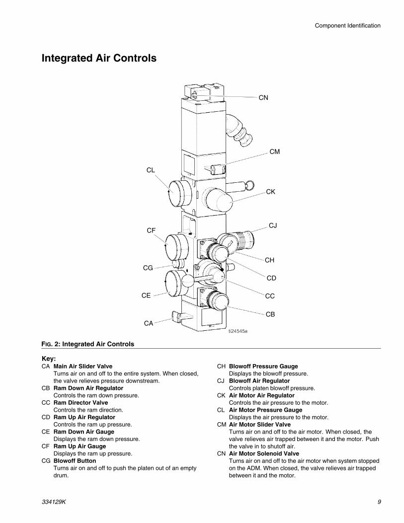
Integrated Air Controls
Key:CA Main Air Slider Valve
Turns air on and off to the entire system. When closed, the valve relieves pressure downstream.
CB Ram Down Air RegulatorControls the ram down pressure.
CC Ram Director ValveControls the ram direction.
CD Ram Up Air RegulatorControls the ram up pressure.
CE Ram Down Air GaugeDisplays the ram down pressure.
CF Ram Up Air GaugeDisplays the ram up pressure.
CG Blowoff ButtonTurns air on and off to push the platen out of an empty drum.
CH Blowoff Pressure GaugeDisplays the blowoff pressure.
CJ Blowoff Air RegulatorControls platen blowoff pressure.
CK Air Motor Air RegulatorControls the air pressure to the motor.
CL Air Motor Pressure GaugeDisplays the air pressure to the motor.
CM Air Motor Slider ValveTurns air on and off to the air motor. When closed, the valve relieves air trapped between it and the motor. Push the valve in to shutoff air.
CN Air Motor Solenoid ValveTurns air on and off to the air motor when system stopped on the ADM. When closed, the valve relieves air trapped between it and the motor.
FIG. 2: Integrated Air Controls
CN
CM
CK
CJ
CH
CD
CC
CBCA
CE
CG
CF
CL
Component Identification
10 334129K
Electrical Control Enclosure
Key:DA Multi-Zone Low Power Temperature Control Module
(MZLP)DB Ventilation GrillDC Electrical Control PanelDD Automatic Wiring Board (AWB)DE Power Supply (24V)DF Residual Current Device (GFI), 63A
DG Platen SSR (65A)DH Platen ContractorDJ Platen FuseDK Transformer Circuit BreakerDL Transformer FuseDM TransformerDN System Contactor
FIG. 3: Electrical Enclosure
DF
DN
DE
DMDC
DD
DB
DA
DKDGDH DJ DL
Back Panel With Transformer
Component Identification
334129K 11
Advanced Display Module (ADM)The ADM display shows graphical and text informationrelated to setup and spray operations. For details on thedisplay and individual screens, see Appendix A - ADM,page 93.
Use the USB port on the ADM to download or upload da-ta. For more information about the USB data, see Ap-pendix B - USB Data, page 101.
NOTICE
To prevent damage to the softkey buttons, do not press buttons with sharp objects such as pens, plastic cards, or fingernails.
FIG. 4: Front View
BB
BC
BA
BH
BG
BD
BEBF
Key FunctionBA Heating system and pump enable/disableBB System status indicator (LED)BC Stop all system processesBD Defined by icon next to softkeyBE Abort current operationBF Accept change, acknowledge error, select
item, toggle selected itemBG Toggle between Operation and Setup
screensBH Navigate within a screen or to a new screen
Component Identification
12 334129K
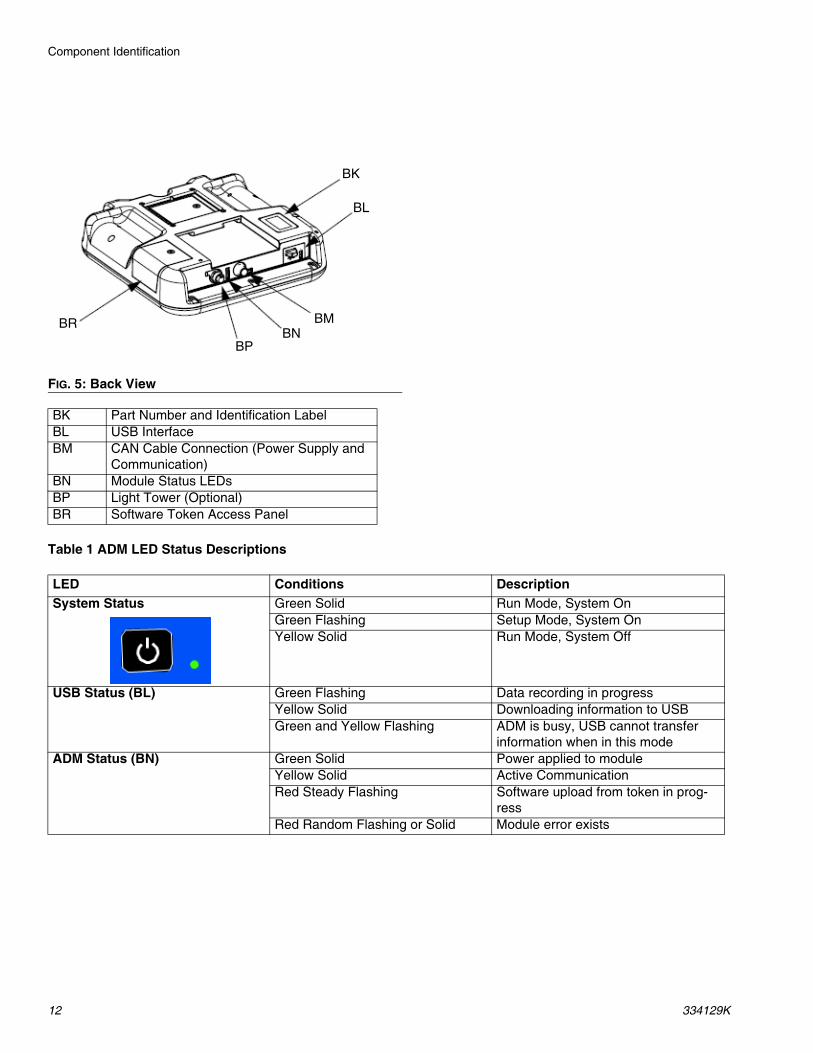
Table 1 ADM LED Status Descriptions
FIG. 5: Back View
BK
BL
BMBN
BP
BR
BK Part Number and Identification LabelBL USB InterfaceBM CAN Cable Connection (Power Supply and
LED Conditions DescriptionSystem Status Green Solid Run Mode, System On
Green Flashing Setup Mode, System OnYellow Solid Run Mode, System Off
USB Status (BL) Green Flashing Data recording in progressYellow Solid Downloading information to USBGreen and Yellow Flashing ADM is busy, USB cannot transfer
information when in this modeADM Status (BN) Green Solid Power applied to module
Yellow Solid Active CommunicationRed Steady Flashing Software upload from token in prog-
ressRed Random Flashing or Solid Module error exists
Component Identification
334129K 13
Screen Components1. Screen Order
2. Current date and time
3. Operating Mode
4. Faults, Status
5. MZLP Plug Identifier
6. Zone Setpoint Temperature
7. Zone Actual Temperature
Operating Mode Description Component StatusSystem Off The system does not have power. • No system status indicator LED on the
ADM• No heat• Pump is off
Inactive The heating system and pumps are dis-abled.
• Yellow system indicator LED on the ADM• No heat• Pump is off
Warm Up The system is heating the material to the setpoint temperature.
• Flashing green system status indicator LED on the ADM
• Heat is increasing to setpoint temperature• Pump is off
Heat Soak Heat zones are all at temperature. Material is soaking for a user specified amount of time.
• Flashing green system status indicator LED on the ADM
• Heat is at setpoint• Material is absorbing more heat• Pump is off• Heat soak counter counts down on the
Home screen.Ready All enabled zones are at setpoint tempera-
ture. The air motor does not have power.• Flashing green system status indicator
LED on the ADM• Heat is at setpoint• Pump is off
Active The system is ready to dispense. • Solid green system status indicator LED on the ADM
• Heat is at setpoint temperature• Pump is on
Overview
14 334129K
OverviewA heated platen melts the sealant or adhesive and directs the molten material to the pump inlet. The mate-rial then travels through a heated pump and heated fluid moves to the application tool.
Air and Fluid HosesThe Therm-O-Flow requires Graco single-circuit mate-rial hoses rated at a maximum of 1250 watts. Make sure all air and fluid hoses are properly sized for the system.
Heat Control ZoneThe Therm-O-Flow has 4, 8, or 12 heat zones. Zones for the heated drum platen and the heated pump are not included in the zone count. Zones 1 and 2, 3 and 4, 5 and 6, 7 and 8, 9 and 10, and 11 and 12 are each avail-able through 12-pin connectors. The heated hoses have a 16-pin connector at the inlet, and an 8-pin connector at the outlet. All heated valves, manifolds, and heaters are equipped with an 8-pin mating connector.
FIG. 6: Heat Control Zone Selection
Setup
334129K 15
Setup1. Unpack the ram
2. Locate and Install the ram
3. Mechanical Setup
4. Connect hoses to electrical control panel
5. Connect electrical control panel to power source
6. Ground system
7. Select ADM settings
Unpack1. Inspect the shipping box carefully for damage. Con-
tact the carrier promptly if there is damage.
2. Open the box and inspect the contents carefully. There should not be any loose or damaged parts in the box.
3. Compare the packing slip against all items in the box. Repost any shortages or other inspection prob-lems immediately.
4. Remove the unit from the skid and place it in the desired location. See Location Requirements.
Location Requirements1. Make sure there is sufficient overhead clearance for
the pump and ram when the ram is in the fully raised position (approximately 75 in. (190.5 cm).)
2. If you are installing a vent hood, make sure there is sufficient horizontal clearance for it. Locate the ram near a connection to the factory ventilation system.
3. Make sure the integrated air controls for the pump and ram are fully accessible, with room to stand directly in front of the controls and the ADM.
4. Make sure there is easy access to an appropriate electrical power source. The National Electrical Code requires 3 ft (0.9 m) of open space in front of the electrical panel. Comply with all local codes and regulations.
5. When locating the system, do not install closer than 36 in. (914 mm) to vertical surfaces.
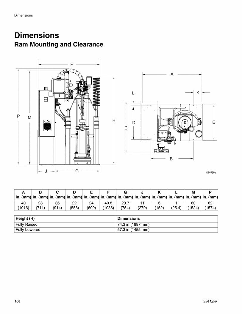
Install SystemRefer to Dimensions, page 104 for mounting and clear-ance dimensions.
Follow all Location Requirements, page 15, when selecting a location for the ram.
1. Apply 50 psi download pressure to ram.
2. Wrap the bar with the lifting sling.
3. Lift the system off the pallet using a crane or a fork-lift and place in desired location.
4. Level the base of the ram, using metal shims.
5. Bolt the ram to the floor, using anchors that are long enough to prevent the unit from tipping.
Setup
16 334129K
Mechanical Setup1. Fill displacement pump wet cup 2/3 full with Graco
Throat Seal Liquid (TSL™) for Butyl and PSA mate-rials.
NOTE: Use IsoGuard Select® (IGS) (part no. 24F516) for PUR or reactive Polyurethane material. IGS is designed to dissolve and suspend the Polyurethane materials. IGS will solidify after a period of time and should be replaced once the solidified lube does not return to liquid form after heating.
2. Turn all air regulators to their full counterclockwise position. See Integrated Air Controls, page 9.
3. Connect a 1/2 in. (13 mm) air line from an air source to the system air inlet (H), capable of delivering a minimum of 25-50 cfm at 100 psi (0.7 MPa, 7.0 bar). Do not use quick disconnects.
4. Ensure drum low and empty sensors (C) are mounted as shown.
NOTE: The Drum Low and Empty Sensors are used to indicate that a drum is empty. The kit contains a sensor mounting bracket (A), activator (B), sensors (C1, C2), and a cable for connecting the panel inside the electrical enclosure.
5. Increase the distance between the low (C1) and empty (C2) sensors to increase the heat up time for the tandem secondary system. Lower the drum empty sensor (C2) to force the heated platen lower into the drum. If empty sensor is set too low, the pump could cavitate and cause an alarm.
FIG. 7: Wetcup
FIG. 8: Air Connection
H
B
CI
C2
A
Setup
334129K 17
Install Heated HoseTo connect a hose to a fluid control device or heated manifold.
1. Install fitting and heated hose onto pump outlet with the large electrical connector side toward the sys-tem. Use 2 wrenches to tighten hose. Torque to 45 ft-lbs (61 N•m).
NOTE: See Accessories and Kits, page 86, for avail-able fittings and heated hoses.
2. Wrap exposed fittings on the pump outlet with Nomex insulation and secure insulation using fiber-glass tape.
3. Connect large heated hose connector to MZLP.
4. Repeat for any remaining channels.
5. Install cap on any unused MZLP electrical connec-tors.
6. Connect the small 8 pin connector from the heated hose to the fluid control device or heated manifold.
NOTE: The heated manifold (part no. 243697) shown. See Accessories and Kits, page 86, for available man-ifolds and fluid control devices.
7. Use 2 wrenches to tighten hose. Torque to 45 ft-lbs (61 N•m).
8. To connect multiple devices, see Connect Multiple Devices, page 18.
FIG. 9
FIG. 10
FIG. 11: Heated Manifold 243697
Setup
18 334129K
Connect Multiple DevicesIf your application requires multiple fluid control devices:
• Connect heated hose electrical connections to the electrical enclosure. Remove from shipping box to connect heated hoses to the electrical enclosure. For additional cables, heated hose, and fluid control devices, see Accessories and Kits, page 86.
• Connect fluid control devices to a heated hose or the electrical enclosure. Use accessories if neces-sary.
• Setup all heat zones on Heat-A and Heat-B screens.
Example: Heated zones used to connect a primary and secondary system to a manifold and two guns. A-# zones are on the Heat-A screen and B-# zones are on the Heat-B screen.
FIG. 12
Setup
334129K 19
Connect PowerThe electrical control panel comes already attached and wired to the ram, however before the supply unit becomes functional you must connect the electrical con-trol panel to a power source.
NOTE: Required voltage and amperage is noted on the control panel label. Before running power to the unit, make sure the plant electrical service meets the machine’s electrical requirements. Branch circuit protec-tion shall be provided by the end user.
Use copper conductors rated 600 volts minimum and 167°F (75°C) minimum only. Torque to 55 in-lb (6.2 N•m).
Table 2 Electrical Requirements
EF Standard Finned BottomEM Mega-FloES Smooth Bottom
1. Locate the opening in the control panel’s top hous-ing for the conduit that will enclose the wire from the facility’s power source. The hole will accept a cord diameter range of 0.7–1.2 in (17–30 mm).
2. Route the wire from the power source into the con-trol panel housing, and then connect the power source wires to the appropriate terminals on the DISCONNECT switch.
3. Connect the ground wire to the ground lug. Have a qualified electrician check the resistance between each Therm-O-Flow system ground and the true earth ground. The resistance must be less than 0.25 ohms. If the resistance is greater than 0.25 ohms, a different ground site may be required. Do not oper-ate the system until the problem is corrected.
NOTE: Use a meter that is capable of measuring resis-tance at this level.
All electrical wiring must be done by a qualified elec-trician and comply with all local codes and regula-tions.
Electrical Panel
Voltage Hz Phase Platen
Full Load Amps AWG
230 V 50/60 3 EF, ES 50 8 AWG400 V/N 50/60 3 EF, ES 30 8 AWG400 V 50/60 3 EF, ES 30 8 AWG480 V 50/60 3 EF, ES 30 8 AWG600 V 50/60 3 EF, ES 25 8 AWG
FIG. 13
To reduce the risk of fire, explosion, or electric shock, the resistance between the supply unit components and true earth ground must be less than 0.25 ohms.
Setup
20 334129K
GroundingGround the unit as instructed here and in the compo-nent manuals.
System: ground through ground lug in electrical enclo-sure. See Connect Power, page 19.
Air and Fluid Hoses: use only electrically conductive hoses.
Air compressor: follow manufacturer’s recommenda-tions.
Spray gun / Dispense valve: ground through connec-tion to a properly grounded fluid hose and pump.
Material drums: follow local code. Use only metal drums placed on a grounded surface. Do not place the drum on a nonconductive surface, such as paper or cardboard, which interrupts the grounding continuity
To maintain grounding continuity when flushing or relieving pressure: follow instructions in your separate gun manual for instructions on how to safely ground your gun while flushing.
Connect Secondary SystemA secondary system is a Therm-O-Flow supply system that connects to the primary Therm-O-Flow system, with the ADM. See Models, page 6 for secondary system model numbers.
1. Connect adapter cable (AC) and communication cable (SC) to the secondary electrical enclosure and rout to splitter (SS) installed on the primary sys-tem.
2. To enable a secondary system, select “Enable Tan-dem System” on the System 1 screen. See Select ADM Settings, page 23.
The equipment must be grounded to reduce the risk of static sparking and electric shock. Electric or static sparking can cause fumes to ignite or explode. Improper grounding can cause electric shock. Grounding provides and escape path for the electric current.
FIG. 14
AC
SC
SS
Setup
334129K 21
Check Sensor Resistance
The package includes up to twelve heat sensors and controllers for each of the heated zones. To check sen-sor resistance:
1. Turn main power switch off.
2. Wait for components to cool down to ambient room temperature 63°-77°F (17°-25°C). Check electrical resistance for the components.
3. Replace any parts whose resistance readings do not comply with the ranges listed in the RTD Sen-sors chart below.
Table 3 RTD Sensors
To reduce risk of injury or damage to equipment, con-duct these electrical checks with the main power switch OFF.
MZLP Pins TOF HoseFirst Heat Zone A, JSecond Heat Zone C, DFirst RTD G, KSecond RTD M, KEarth Ground B
MZLP MZLP Plug ComponentRTD Range
(Ohms)Ram Plate 100 +/- 2Fluid Pump 100 +/- 2
1
1, 2
Heated Accessory 1 100 +/- 2
Heated Accessory 2 100 +/- 2
3, 4
Heated Accessory 3 100 +/- 2
Heated Accessory 4 100 +/- 2
2
5, 6
Heated Accessory 5 100 +/- 2
Heated Accessory 6 100 +/- 2
7, 8
Heated Accessory 7 100 +/- 2
Heated Accessory 8 100 +/- 2
3
9, 10
Heated Accessory 9 100 +/- 2
Heated Accessory 10
100 +/- 2
11, 12
Heated Accessory 11
100 +/- 2
Heated Accessory 12
100 +/- 2
Setup
22 334129K
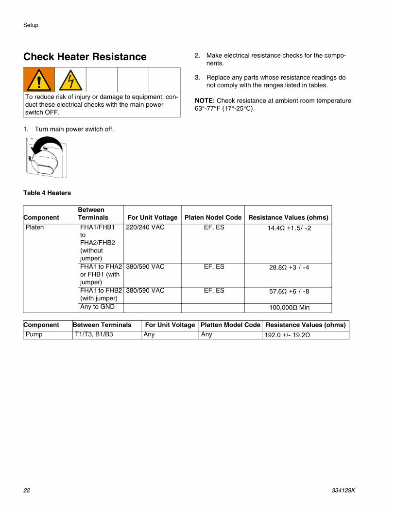
Check Heater Resistance
1. Turn main power switch off.
2. Make electrical resistance checks for the compo-nents.
3. Replace any parts whose resistance readings do not comply with the ranges listed in tables.
NOTE: Check resistance at ambient room temperature 63°-77°F (17°-25°C).
Table 4 Heaters
To reduce risk of injury or damage to equipment, con-duct these electrical checks with the main power switch OFF.
ComponentBetween Terminals For Unit Voltage Platen Nodel Code Resistance Values (ohms)
Platen FHA1/FHB1toFHA2/FHB2 (without jumper)
220/240 VAC EF, ES 14.4Ω +1.5/ -2
FHA1 to FHA2 or FHB1 (with jumper)
380/590 VAC EF, ES 28.8Ω +3 / -4
FHA1 to FHB2 (with jumper)
380/590 VAC EF, ES 57.6Ω +6 / -8
Any to GND 100,000Ω Min
Component Between Terminals For Unit Voltage Platten Model Code Resistance Values (ohms)Pump T1/T3, B1/B3 Any Any 192.0 +/- 19.2Ω
Setup
334129K 23
Select ADM SettingsNOTE: See Appendix A - ADM, page 93 for detailed ADM information, including general operation.
1. Turn main power switch on.
2. When the ADM is finished starting up, press to switch from the Operation screens to the Setup screens. Use the arrows to navigate between screens.
3. Check system settings on the System 1 screen.
4. Set alarm levels on the System 2 screen.
5. Set primary system setpoint and setback tempera-tures for the pump, platen, and heat zones on the Heat-A-screens.
NOTE: Setback temperatures must be at least 20°F (10°C) lower than the setpoint temperatures.
NOTE: To ensure accurate hose temperatures, be sure all heated hoses have their “zone type” set to “Hose.” Hoses are only present on odd zone numbers: 1, 3, 5, 7, 9, or 11.
a. Select the appropriate “Zone Type” for all installed zones.
b. Check the “A” and “B” boxes according to which systems needs to use the heated accessory.
6. If a secondary system is used, set temperatures on the Heat-B-screens.
7. Set the system date and time on the Advanced 1 screen.
Setup
24 334129K
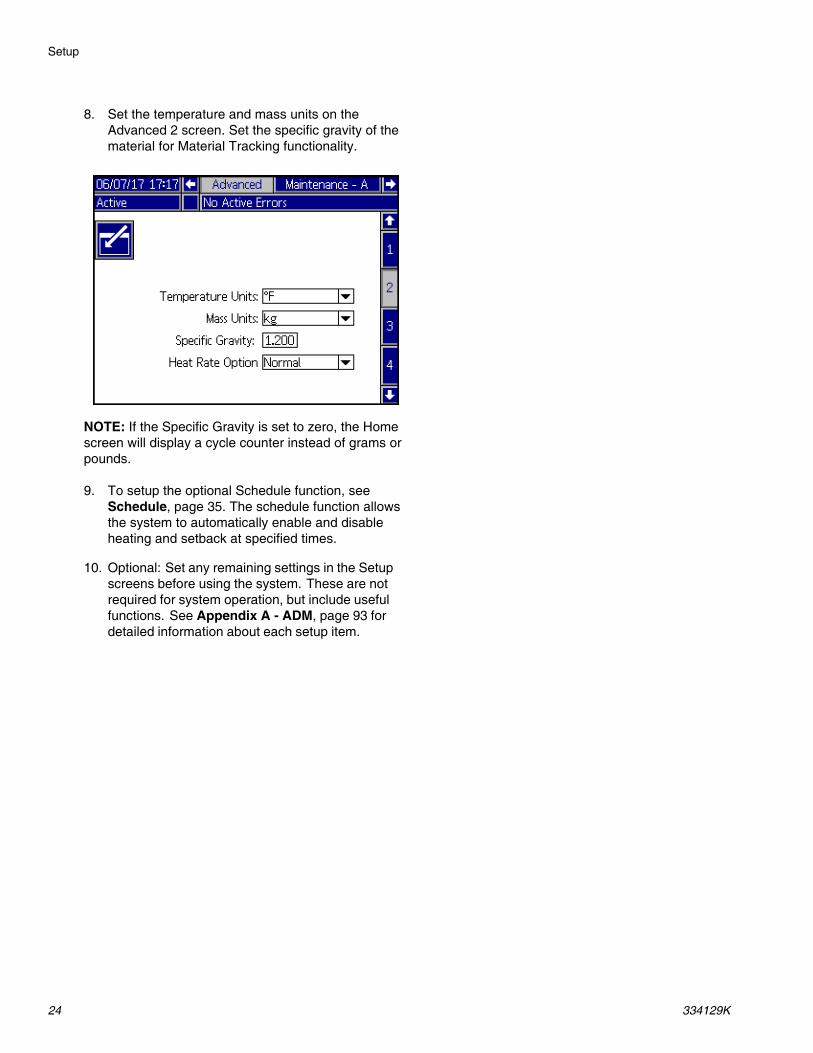
8. Set the temperature and mass units on the Advanced 2 screen. Set the specific gravity of the material for Material Tracking functionality.
NOTE: If the Specific Gravity is set to zero, the Home screen will display a cycle counter instead of grams or pounds.
9. To setup the optional Schedule function, see Schedule, page 35. The schedule function allows the system to automatically enable and disable heating and setback at specified times.
10. Optional: Set any remaining settings in the Setup screens before using the system. These are not required for system operation, but include useful functions. See Appendix A - ADM, page 93 for detailed information about each setup item.
Setup
334129K 25
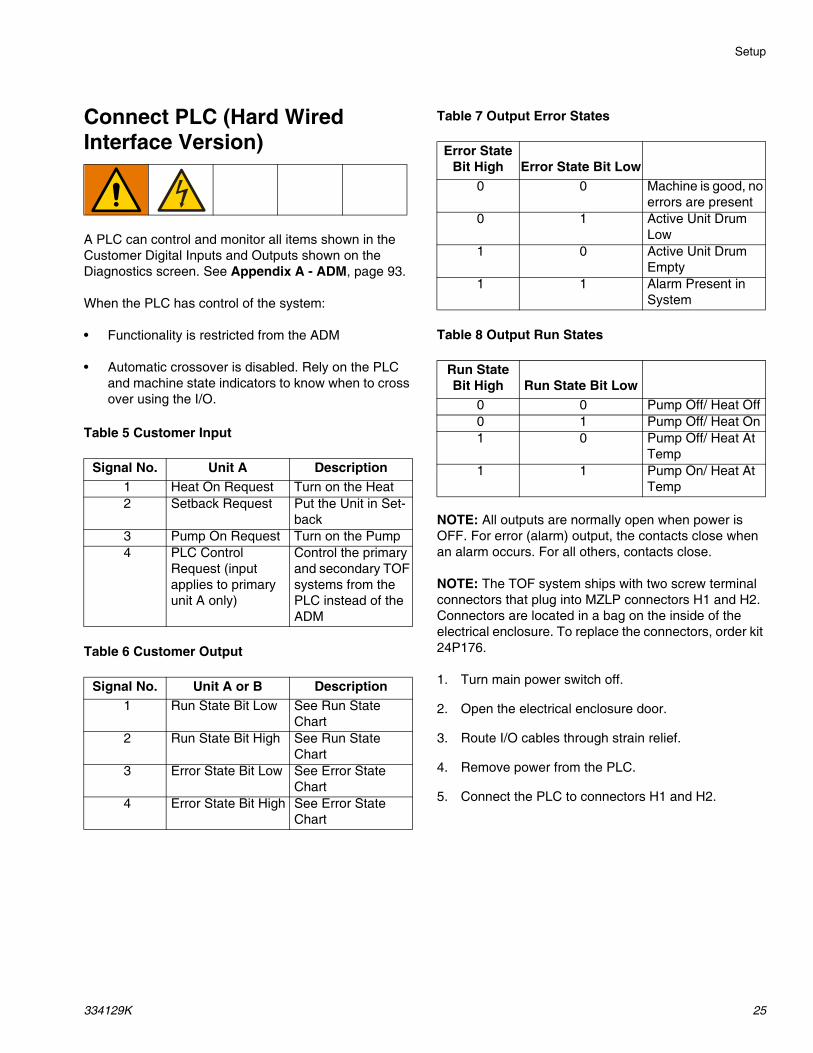
Connect PLC (Hard Wired Interface Version)
A PLC can control and monitor all items shown in the Customer Digital Inputs and Outputs shown on the Diagnostics screen. See Appendix A - ADM, page 93.
When the PLC has control of the system:
• Functionality is restricted from the ADM
• Automatic crossover is disabled. Rely on the PLC and machine state indicators to know when to cross over using the I/O.
Table 5 Customer Input
Table 6 Customer Output
Table 7 Output Error States
Table 8 Output Run States
NOTE: All outputs are normally open when power is OFF. For error (alarm) output, the contacts close when an alarm occurs. For all others, contacts close.
NOTE: The TOF system ships with two screw terminal connectors that plug into MZLP connectors H1 and H2. Connectors are located in a bag on the inside of the electrical enclosure. To replace the connectors, order kit 24P176.
1. Turn main power switch off.
2. Open the electrical enclosure door.
3. Route I/O cables through strain relief.
4. Remove power from the PLC.
5. Connect the PLC to connectors H1 and H2.
Signal No. Unit A Description1 Heat On Request Turn on the Heat2 Setback Request Put the Unit in Set-
back3 Pump On Request Turn on the Pump4 PLC Control
Request (input applies to primary unit A only)
Control the primary and secondary TOF systems from the PLC instead of the ADM
Signal No. Unit A or B Description1 Run State Bit Low See Run State
NOTE: Each connector has four signals. The MZLP board specifies the input range for each signal. See the following table for pin assignments.
Inputs: High: 10–30 VDC, Low: 0–5 VDC. Inputs func-tion without concern for polarity. Applying “high” voltage will turn the heaters on and enable setback. Removing voltage will turn the heaters off and disable setback.
Outputs: 0–250 VAC, 0–30 VDC, 2A Maximum.
FIG. 15
H1 Customer Input
Signal Pin1 1,22 3,43 5,64 7,8
H2 Customer Output
Signal Pin1 1,22 3,43 5,64 7,8
Setup
334129K 27
PLC Connections Block DiagramsThe following block diagrams show how to connect customer inputs and outputs to the MZLP. For convenience, each system ships with connector kit 24P176. If a connector is lost or damaged, order kit 24P176 for replacements.
FIG. 16: Customer Input
FIG. 17: Customer Output
Operation
28 334129K
Operation1. Turn the main power switch ON. The Graco logo will
display until communication and initialization is com-plete.
2. Press the button. Verify the machine is in “Warm Up” state, and that the temperatures are increasing. Allow the system to reach the “Ready” state before pumping. The pump will automatically turn on, if autostart is enabled in setup screens, when all the heat zones reach their setpoint tem-perature.
Purge System
1. Select the material for the initial material load.
2. Verify whether the factory-test oil and the initial material load are compatible:
a. If the two substances are compatible omit the remaining steps in this procedure and refer to Load Material, page 29.
b. If the two substances are incompatible perform the remaining steps in this procedure to flush the system.
3. Select a pail of material that can eliminate the fac-tory-test oil from the system. If necessary, check with Graco or the material supplier for a recom-mended solvent.
4. Before purging, be sure the entire system and waste pail are properly grounded. See Grounding, page 20.
5. Turn all heat zones’ setpoint temperature to the material manufacturer’s recommended dispense temperature, or a minimum of 100°F (37°C) mini-mum.
NOTE: Remove any dispense valve orifices before purging. Reinstall after purging has been completed.
6. Purge the material through the system for approxi-mately 1 to 2 minutes.
7. Remove the pail if purge material was used. See Change Pail, page 36.
NOTICE
Purge the system before initial use and when chemi-cals are changed to prevent material contamination, which may cause the material to fail or perform poorly. The system was factory- tested using a light soluble oil, a soybean oil, or some other oil as tagged. Flush the system to avoid contaminating the material that has been designated for initial material loading.
NOTICE
Use fluids that are chemically compatible with the equipment wetted parts. See Technical Specifica-tions in all of the equipment manuals.
Operation
334129K 29
Load Material
NOTE: Before loading material, make sure there is a minimum overhead clearance of 75 in. (191 cm) and all air regulators are backed off to their full counterclock-wise position.
1. Open the main air slider valve (CA).
2. Set ram director valve (CC) to UP and slowly turn the ram up regulator (CD) clockwise until the platen (G) begins to rise.
3. Apply a thin coating of high temperature grease lubricant (part no. 115982) to the platen pail seals.
4. Fill displacement pump wet cup 2/3 full with Graco Throat Seal Liquid (TSL™) for Butyl and PSA mate-rials.
NOTE: Use IsoGuard Select® (IGS) (part no. 24F516) for PUR or reactive Polyurethane material. IGS is designed to dissolve and suspend the Polyurethane materials. IGS will solidify after a period of time and should be replaced once the solidified lube does not return to liquid form after heating.
5. Open pail, remove any packing material, and inspect material for any contamination.
6. Slide the pail against the stops at the back of the ram baseplate.
NOTICETo prevent damage to platen wipers, do not use a pail of material that has been dented or damaged. An empty pail clamp can interfere with up and down opera-tion of the ram. When raising the ram, make sure the pail clamp stays clear of the platen.
FIG. 18: Raise the Platen
CA
CD
CC
FIG. 19: Wetcup
FIG. 20: Drum Placement
Operation
30 334129K
7. Remove the platen bleed stick (R).
8. Set ram director valve (CC) to down and lower the platen.
9. Slowly turn the ram down air regulator (CB) clock-wise to approximately 5–10 psi (34–69 kpa, 0.3–0.7 bar). The platen will begin to lower into the pail.
10. After the platen seals enter the material pail, adjust the ram down air regulator (CB) to 30–50 psi (207–345 kPa, 2.1–3.4 bar).
11. When the ram stops, reinsert the platen bleed stick (R) and hand tighten.
Heat Up System
NOTE: Operate at the lowest temperature and pressure necessary for your application.
1. Turn the main power switch on the electrical control panel door to the ON position.
2. Press the button. The zones begin to heat
(provided they are enabled). Press if the zones do not begin to heat. Display status bar reads Warm Up. When temperature reaches setpoint, the display status bar reads Heat Soak. When heat is on, the status will display in the status bar. See Advanced Display Module (ADM), page 11, for operation mode descriptions.
NOTE: The air will be locked from the air motor until all temperature zones are within a preset window of the temperature setpoints, allowing the system to heat fully and complete the material heat soak period.
FIG. 21: Platen Bleed Handle
FIG. 22: Lower the Platen
R
CC
CB
To reduce the risk of bursting a hose, never pressur-ize a hot melt system before turning on the heat. The air will be locked from the air motor until all tempera-ture zones are within a preset window of the tempera-ture setpoints.
Keep the dispense valve open over a waste container while the system is heating up and also when cooling down. This will prevent a pressure build-up caused by fluids or gases expanding from the heat.
Operation
334129K 31
Prime Pump
1. Ensure that the system has completed the heat soak cycle. The display status bar should read Active.
2. Adjust the air motor air regulator (CK) to 0 psi.
3. Adjust the air motor slider valve (CM) to the open position.
4. Adjust the air motor air regulator (CK) to approxi-mately 20 psi (138 kPa, 1.38 bar).
5. Place a waste container under the bleed stem (Z). Using an adjustable wrench, open the bleed stem counterclockwise 1/3 -1/2 turn.
CK
CN
CM
CK
Z
Operation
32 334129K
6. If a new pail was installed and the unit is equipped with proximity sensors, press the Pump Ready but-
ton . Press the pause button on material tracking.
7. Adjust the air motor air regulator (CK) up by 5 psi (34 kPa, 0.3 bar). Never adjust the regulator by more than 5 psi (34 kPa, 0.3 bar) increments. Make sure the pump begins to cycle and heated material flows from the bleed stem (Z) after several cycles of the pump.
8. Prime the pump until it moves smoothly in both directions with no air popping or erratic movement and close the main air slider valve (CA).
9. Press the Play button on the home screen to enable material tracking and press the pump ready button.
For Tandem OperationComplete steps 1-5 on page 31 for the inactive unit. Note that the heat will remain on for the inactive unit until the system is turned off.
6. If a new drum has been installed in the inactive unit,
press the Pump Ready button on the inactive unit. The light on the solenoid of the inactive unit should be on (CN).
7. Adjust the air motor air regulator (CK) up by 5 psi (34 kPa, 0.3 bar). Never adjust the regulator by more than 5 psi (34 kPa, 0.3 bar) increments. Make sure the pump begins to cycle and heated material flows from the bleed stem (Z) after several cycles of the pump.
8. Prime the pump until it moves smoothly in both directions with no air popping or erratic movement and close the bleed stem (Z).
9. Press the Pump Ready button for the inactive unit.
CA
Operation
334129K 33
Prime System
1. Close the main air slider valve (CA).
2. If using a manual gun, lock the dispense valve trig-ger open by pulling and securing the trigger using the trigger retainer (Z).
3. Place the dispense valve over a waste container.
4. Press the pause material tracking button on home screen.
5. Slowly open the main air slider valve (CA).
6. Prime the system until a smooth flow of material dis-penses from each dispense valve.
NOTE: On initial system startup, the pump will cycle until the hoses are filled. If a new drum was placed on the frame, the pump will cycle until all air has been removed.
7. Close the main air slider valve (CA) and release the trigger lock.
8. Engage the trigger lock.
9. Press to engage material tracking.
10. Turn the air motor regulator to operating pressure.
NOTE: The system is now ready to operate.
Setback ModeSet the ADM to setback mode if the system will only be inactive for a few hours. This will reduce the time the system needs to return to setpoint temperatures.
1. Press to enter Setback Mode.
NOTE: The amount of time before the pump is automat-ically placed in setback is determined by the Pump Inac-tivity Timeout, located on System Setup Screen 1. See Setup Screens, page 97.
CA
Z
FIG. 23: Trigger Lock Engaged
Operation
34 334129K
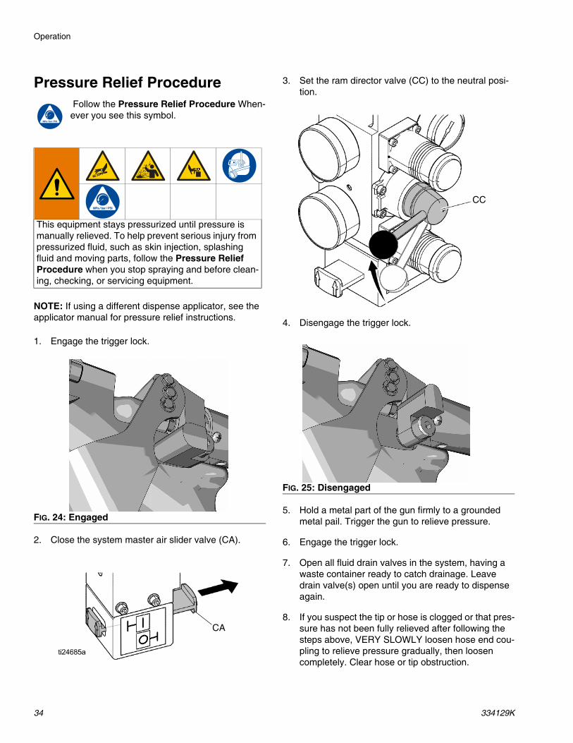
Pressure Relief Procedure Follow the Pressure Relief Procedure When-ever you see this symbol.
NOTE: If using a different dispense applicator, see the applicator manual for pressure relief instructions.
1. Engage the trigger lock.
2. Close the system master air slider valve (CA).
3. Set the ram director valve (CC) to the neutral posi-tion.
4. Disengage the trigger lock.
5. Hold a metal part of the gun firmly to a grounded metal pail. Trigger the gun to relieve pressure.
6. Engage the trigger lock.
7. Open all fluid drain valves in the system, having a waste container ready to catch drainage. Leave drain valve(s) open until you are ready to dispense again.
8. If you suspect the tip or hose is clogged or that pres-sure has not been fully relieved after following the steps above, VERY SLOWLY loosen hose end cou-pling to relieve pressure gradually, then loosen completely. Clear hose or tip obstruction.
This equipment stays pressurized until pressure is manually relieved. To help prevent serious injury from pressurized fluid, such as skin injection, splashing fluid and moving parts, follow the Pressure Relief Procedure when you stop spraying and before clean-ing, checking, or servicing equipment.
FIG. 24: Engaged
CA
FIG. 25: Disengaged
CC
Operation
334129K 35
Shutdown
1. Press to disable the heaters and pump. The screen will say “Inactive”. If using the Schedule func-tion, the heaters and pump will be disabled automat-
ically at the set time. Only press to disable the heating system before the set time. If the heaters were manually disabled, the Schedule function will automatically enable them at the next set time.
NOTE: Do not perform step 2 if using the Schedule func-tion. Leave the power on.
2. Turn the main power switch off.
ScheduleThe Schedule function allows the user to specify times when the system will automatically turn ON and OFF the heaters and pump.
Table 9 Schedule Screen Color Identification
Set Schedule TimesTimes are set using a 24-hour clock. Several on and off times can be set each day.
1. On the Schedule screen (in the Setup screens), set the ON times for each day of the week
2. Set the OFF times for each day of the week.
3. Set the setback times for each day of the week.
Enable Schedule FunctionThe Schedule function is automatically enabled when values are entered in the Schedule screen. To disable a
scheduled event, navigate to the event and press .
The event will appear gray on the screen when it is dis-abled. To re-enable an event, navigate to the event and
press .
The event will appear red (system off), yellow (system setback), or green (system on). If no events are needed, turn the main power switch OFF to prevent system from automatically enabling and disabling the heaters.
Color DescriptionGreen System onYellow SetbackRed System offGray Disabled
Operation
36 334129K
Use the Schedule FunctionAt the end of the work day leave the main power switch ON. The Schedule function will automatically enable and disable the heaters and pump at the specified times.
Change Pail
Follow the procedure to change the pail on a fully heated system.
All systems include Low/Empty Sensors:
• The air will shutoff to prevent the pump from cavita-tion. If the light tower kit is installed, a solid red light indicates that the pail is empty and ready to change.
• In a tandem system, a flashing red light means that both drums are empty and the system has shut-down.
1. Press to stop material tracking.
2. Push in the air motor slider valve (CM) to stop the pump.
3. Set ram director valve (CC) to UP and raise the platen (G) and immediately press and hold the blowoff buttons (CG) until the platen is completely out of the pail. Use the minimum amount of air pres-sure necessary to push the platen out of the pail.
4. Release the blowoff air button and allow the ram to rise to its full height.
5. Remove the empty pail.
6. Inspect platen and if necessary, remove any remaining material or material build-up.
7. Follow steps in Load Material, page 29, and Prime Pump, page 31.
To prevent serious burns from dripping material, never reach under the heated platen after the platen is out of the pail.
NOTICEBe sure to reload the empty supply unit with a full pail of material immediately. Do not raise the ram and remove the platen from the empty pail until you are ready to immediately install a new pail.
Do not raise the ram and remove the platen from the empty pail unless the supply unit is at full oper-ating temperature. Drum changes can only be per-formed when the system is heated.
An empty pail clamp can interfere with the up and down operation of the ram. When raising or lowering the ram, make sure the pail clamp stays clear of the platen assembly.
Do not use a pail of material that has been dented or otherwise damaged; damage to the platen wipers can result.
Excessive air pressure in the material pail could cause the pail to rupture, causing serious injury. The platen must be free to move out of the pail. Never use pail blowoff air with a damaged pail.
CM
CC
CG
Troubleshooting
334129K 37
Troubleshooting
Light Tower (Optional)Signal DescriptionRed Light Off If green light is also off, system power may be off or system operating mode is Inactive. If
green is on or flashing, there are no active errorsRed Light On User interaction required — alarm, system is shut downRed Light Flashing User interaction required — advisory, deviation, or system is in a state that could prohibit
dispensingGreen Light Off System is inactiveGreen Light On System is ready to dispense. The heat and pump are on.Green Light Flashing System will be ready to dispense in time without user interaction (heat on, pump off, and
temperature control zones have not reached set point)
Troubleshooting
38 334129K
Error CodesThere are three types of errors that can occur. Errors are indicated on the display as well as by the optional light tower.
Alarms are indicated by . This condition indicates a parameter critical to the process has reached a level requiring the system to stop. The alarm needs to be addressed immediately.
Deviations are indicated by . This condition indicates a parameter critical to the process has reached a level requiring attention, but not sufficient enough to stop the system at this time.
Advisories are indicated by . This condition indicates a parameter that is not immediately critical to the pro-cess. The advisory needs attention to prevent more seri-ous issues in the future.
To acknowledge the error, press .
The third digit, or sometimes the last digit of the error code, indicates which unit the error is active on. The “” (star) character indicates the code applies to multiple system components.
The last digit of the error code indicates which system component the error applies. The “#” (pound) character indicates the code applies to multiple system compo-nents.
The last digit of the error code indicates which heat zone the error applies. The “_” (underscore) character indi-cates the code applies to multiple system components.
Third or Last Digit “” Code Relates To:A Unit AB Unit B
Last Digit “#”Code Relates To System Component:
1 MZLP 12 MZLP 23 MZLP 35 MZLP 56 MZLP 67 MZLP 7G Gateway (CGM)H Gateway Heartbeat LossV AWB Unit AW AWB Unit BX Daughter Board Unit AY Daughter Board Unit B
Last Digit “_”Code Relates To Heat Zone:
1 Zone 12 Zone 23 Zone 34 Zone 45 Zone 56 Zone 67 Zone 78 Zone 89 Zone 9A Zone 10B Zone 11C Zone 12D PumpE Platen
Troubleshooting
334129K 39
Code Description Type Cause Solution
A3MF AWB Clean Fan Filter Alarm Cooling inlet screen is dirty
Clean inlet screen.
A4 _ High Current Unit _ Zone _
Alarm Defective or shorted to ground on zone
Verify accessory is rated for 240 VAC.Verify heater resistance and check for shorts to ground. Replace as necessary.
A4C# High Current Fan AWB, Unit _
Deviation Fan is drawing too much cur-rent
Verify there is not an air obstruction at the inlet/outlet of enclosure. Verify nothing is preventing fan rotation. Replace fan if necessary.
A7 _ Unexp. Curr. Unit _ Zone _
Alarm Unexpected current flow to zone
Replace MZLP.
Faulty accessory heater. Measure resistance to ground between heater leads.
A8 _ No Current Unit _ Zone _
Alarm No Current Flow to the Zone
Check for loose or disconnected wires or plugs.Check for blown fuses on MZLP.Check heater resistance for open circuit.Check for shorts between heater and ground.Verify cable is plugged into zones 3-4. Replace heater if necessary.
A8C AWB No Fan Current Alarm Cooling Fan not Working
Verify fan is plugged in. Replace if necessary.
AM3# High Current SSR MZLP _
Alarm Excessive current flow in the SSR
Check for shorts in harness to SSR. Check polarity of wiring to SSR. Replace if necessary.
AM4# High Current Contactor MZLP _
Alarm Defective or shorted to ground on MZLP
Check for shorts in the harness to contactor. Check the polarity to contactor. Replace contactor if necessary.
AM8# No Current Contactor MZLP _
Alarm No Current Flow to the Contactor
Ensure harness to MZLP is connected. Ensure wiring to contactor is secure. Replace contactor if necessary.
CAC# Comm Error MZLP _ Alarm System not responding to ADM
System is not properly loaded with correct Soft-ware.
Dial not set correct on MZLP. Duplicate MZLP dialpositions (i.e. 1 to 1, 2 to 2, ect).
Check all CAN connections between the ADM and missing MZLP.Check if hardware exists on the network.Replace MZLP if necessary.
CACX DB Not Present Unit A Alarm Daughter Board not responding
Dial not set correct on MZLP 5. Set to 5 on board with daughter board.Ensure connections between the ADM and hardware are secure.Replace Daughter Board.
Troubleshooting
40 334129K
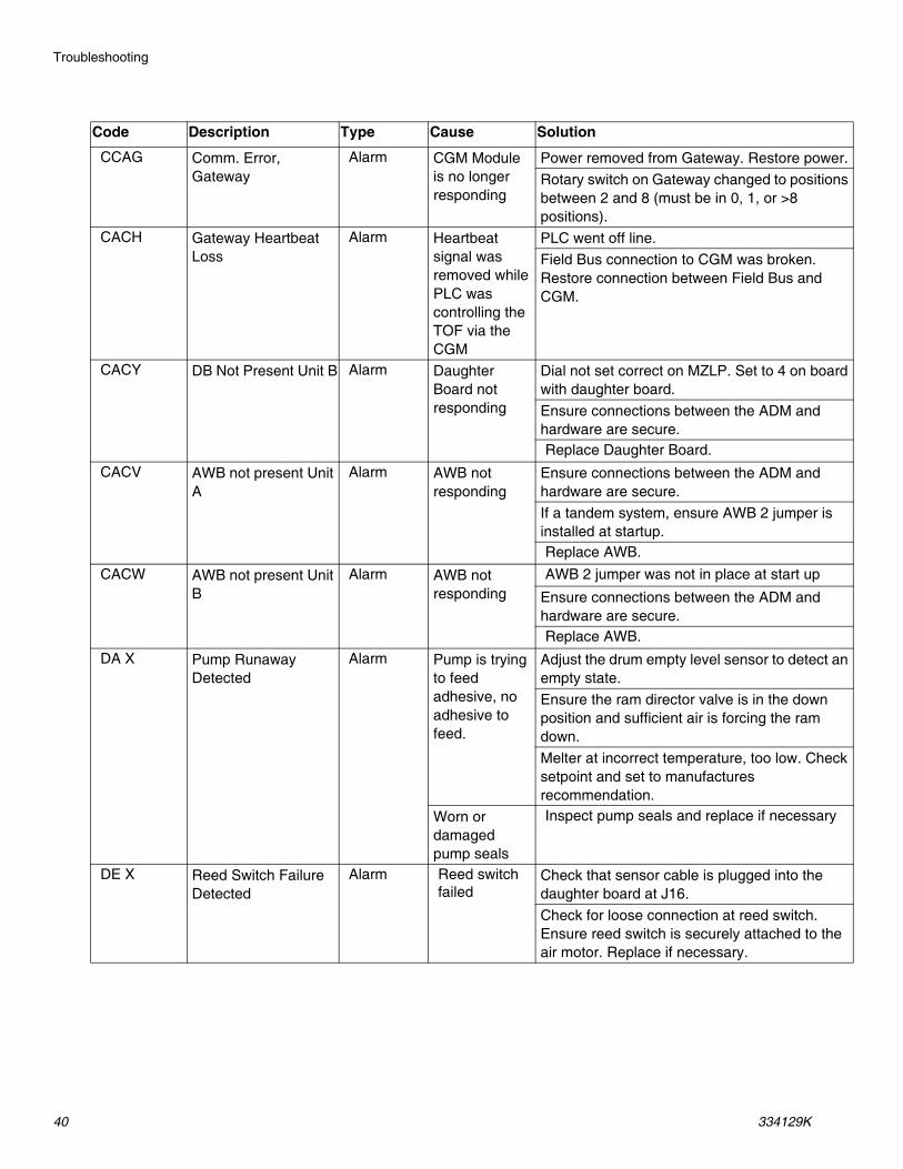
CCAG Comm. Error, Gateway
Alarm CGM Module is no longer responding
Power removed from Gateway. Restore power.Rotary switch on Gateway changed to positions between 2 and 8 (must be in 0, 1, or >8 positions).
CACH Gateway Heartbeat Loss
Alarm Heartbeat signal was removed while PLC was controlling the TOF via the CGM
PLC went off line.Field Bus connection to CGM was broken. Restore connection between Field Bus and CGM.
CACY DB Not Present Unit B Alarm Daughter Board not responding
Dial not set correct on MZLP. Set to 4 on board with daughter board.Ensure connections between the ADM and hardware are secure.Replace Daughter Board.
CACV AWB not present Unit A
Alarm AWB not responding
Ensure connections between the ADM and hardware are secure.If a tandem system, ensure AWB 2 jumper is installed at startup.Replace AWB.
CACW AWB not present Unit B
Alarm AWB not responding
AWB 2 jumper was not in place at start up
Ensure connections between the ADM and hardware are secure.Replace AWB.
DA X Pump Runaway Detected
Alarm Pump is trying to feed adhesive, no adhesive to feed.
Adjust the drum empty level sensor to detect an empty state.Ensure the ram director valve is in the down position and sufficient air is forcing the ram down.Melter at incorrect temperature, too low. Check setpoint and set to manufactures recommendation.
Worn or damaged pump seals
Inspect pump seals and replace if necessary
DE X Reed Switch Failure Detected
Alarm Reed switch failed
Check that sensor cable is plugged into the daughter board at J16.Check for loose connection at reed switch. Ensure reed switch is securely attached to the air motor. Replace if necessary.
Code Description Type Cause Solution
Troubleshooting
334129K 41
DC X Pump Diving Alarm Pump is trying to feed adhesive, no adhesive to feed.
Adjust the drum empty level sensor to detect an empty state.Ensure the ram director valve is in the down position and sufficient air is forcing the ram down.Melter at incorrect temperature, too low. Check setpoint and set to manufactures recommendation.
Worn or damaged pump seals
Inspect pump seals and replace if necessary
L1 X Material Level Sen-sor Error
Alarm Machine is detecting an empty state without a low state
Make sure the empty level sensor is not covered in materialVerify the low level sensor is plugged into J15 of the daughter board. Verify the low level sensor is close enough to the metal bar; adjust if necessary.Replace sensors.
L2 X Material Level Empty Alarm Material drum is empty
Replace material container. If more material is leftover, lower the empty level sensor.
L3 X Material Level Low Deviation Material level is low
Replace at appropriate time.
MMUX USB Log Full Advisory USB logs fulls. Data loss will occur if not downloaded.
Download USB data or disable the USB log errors on the Advanced screen 3.
MN X Pump _ Requires Maintenance
Advisory User defined pump maintenance counter has run out
Perform pump maintenance, then reset the counter on the maintenance setup screen.
T1 _ Low Temp. Unit _ Zone _
Alarm Zone temperature too low
Reduce flow rate.Increase temperature of accessory upstream.
Reduce flow rate.Change Low Temp Deviation Offset.Add zone (temperature) upstream.
T3 _ High Temp. Unit _ Zone _
Deviation Temperature reading has risen too high
Change High Temp Deviation Offset.
Verify setpoint upstream is not hotter than this zone’s setpoint.
T4C# AWB Temperature Runaway Transformer
Alarm Cooling fan not working or inlet is blocked/dirty
Ensure inlet and outlets are not obstructed.Verify fan is plugged in.
Code Description Type Cause Solution
Troubleshooting
42 334129K
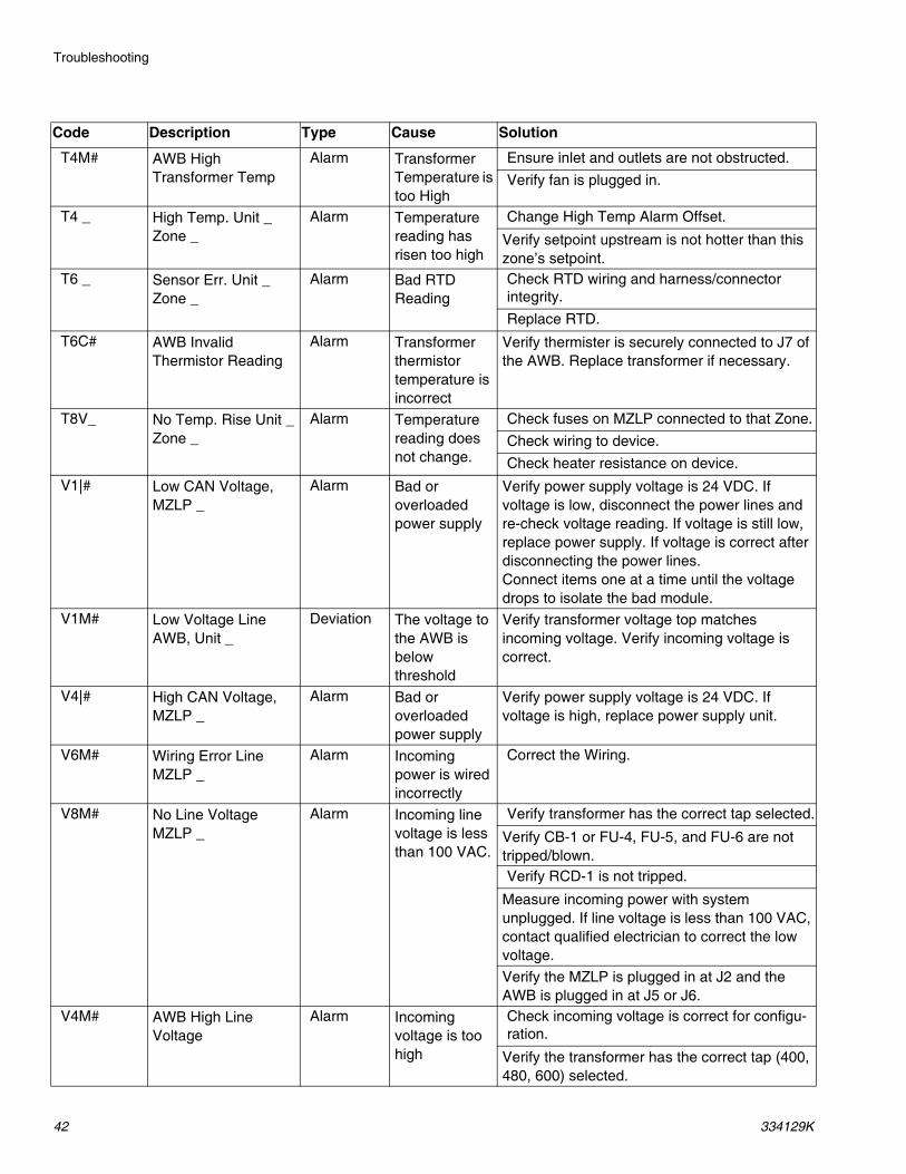
T4M# AWB High Transformer Temp
Alarm Transformer Temperature is too High
Ensure inlet and outlets are not obstructed.Verify fan is plugged in.
T4 _ High Temp. Unit _ Zone _
Alarm Temperature reading has risen too high
Change High Temp Alarm Offset.
Verify setpoint upstream is not hotter than this zone’s setpoint.
T6 _ Sensor Err. Unit _ Zone _
Alarm Bad RTD Reading
Check RTD wiring and harness/connector integrity.Replace RTD.
T6C# AWB Invalid Thermistor Reading
Alarm Transformer thermistor temperature is incorrect
Verify thermister is securely connected to J7 of the AWB. Replace transformer if necessary.
T8V_ No Temp. Rise Unit _ Zone _
Alarm Temperature reading does not change.
Check fuses on MZLP connected to that Zone.Check wiring to device.Check heater resistance on device.
V1|# Low CAN Voltage, MZLP _
Alarm Bad or overloaded power supply
Verify power supply voltage is 24 VDC. If voltage is low, disconnect the power lines and re-check voltage reading. If voltage is still low, replace power supply. If voltage is correct after disconnecting the power lines.Connect items one at a time until the voltage drops to isolate the bad module.
V1M# Low Voltage Line AWB, Unit _
Deviation The voltage to the AWB is below threshold
Verify transformer voltage top matches incoming voltage. Verify incoming voltage is correct.
V4|# High CAN Voltage, MZLP _
Alarm Bad or overloaded power supply
Verify power supply voltage is 24 VDC. If voltage is high, replace power supply unit.
V6M# Wiring Error Line MZLP _
Alarm Incoming power is wired incorrectly
Correct the Wiring.
V8M# No Line Voltage MZLP _
Alarm Incoming line voltage is less than 100 VAC.
Verify transformer has the correct tap selected.
Verify CB-1 or FU-4, FU-5, and FU-6 are not tripped/blown.Verify RCD-1 is not tripped.
Measure incoming power with system unplugged. If line voltage is less than 100 VAC, contact qualified electrician to correct the low voltage.Verify the MZLP is plugged in at J2 and the AWB is plugged in at J5 or J6.
V4M# AWB High Line Voltage
Alarm Incoming voltage is too high
Check incoming voltage is correct for configu-ration.
Verify the transformer has the correct tap (400, 480, 600) selected.
Code Description Type Cause Solution
Troubleshooting
334129K 43
WJ1 Pump _ Solenoid is disconnected
Alarm Pump is not turning on when it should
Verify harness is plugged into J13 of the daughter board. Verify it is secured to the solenoid.Replace Solenoid.
WJ2 Pump _ Solenoid High Current
Alarm Solenoid is drawing too much current
Inspect for short in harness. Inspect for a shorted solenoid cable/short to the ground. Replace solenoid.
WSUX Configuration Error USB
Advisory USB configuration is not loaded
Install software.
Code Description Type Cause Solution
Troubleshooting
44 334129K
Ram TroubleshootingProblem Cause Solution
Ram will not raise or lower. Closed main air valve or clogged air line,
Open air valve; clear air line.
Not enough ram air pressure. Increase ram air pressure.Worn or damaged ram piston. Replace piston. See instruction man-
ual 310523.Platen not fully up to temperature. Wait for full temperature.Ram air pressure too high. Decrease ram air pressure.Dented drum has stopped platen. Fix or replace drum.
Ram raises or lowers too fast. Ram "up / down" air pressure too high.
Decrease ram air pressure.
Air leaks around cylinder rod. Worn rod seal. Replace o-rings in guide sleeve. See instruction manual 310523.
Fluid squeezes past platen wipers. Ram air pressure too high. Decrease ram air pressure.Worn or damaged wipers. Replace wipers.
Pump will not prime properly, or pumps air.
Closed main air valve or clogged air line.
Open air valve; clear air line.
Not enough air pressure. Increase air pressure.Worn or damaged ram piston. Replace piston. See instruction man-
ual 310523.Ram directional valve closed or clogged.
Open valve; clear valve or exhaust.
Ram directional valve dirty, worn, or damaged.
Clean; repair valve.
Directional valve not in the down position.
Position handle in the down position.
Dented drum has stopped platen. Fix or replace drum.Air pressure will not push platen out of drum.
Closed main air valve or clogged air line.
Open air valve; clear air line.
Platen not fully up to temperature. Wait for full temperature.Not enough blow-off air pressure. Increase blow-off air pressure.Blow-off valve passage clogged. Clean valve passage.Dented drum has stopped platen. Fix or replace drum.Wipers bonded to drum or drum liner. Lubricate wipers with high tempera-
ture grease at every drum change.
Troubleshooting
334129K 45
Heated Pump Troubleshooting
See pump manual for additional pump troubleshooting information. See Related Manuals, page 7.
Air Motor Troubleshooting
See air motor manual for additional air motor troubleshooting information. See Related Manuals, page 7.
Problem Cause Solution
Rapid downstroke or upstroke (pump cavitation).
Material not heated to proper temperature.
Check and adjust temperature to proper setpoint. Wait for pump/platen to heat up.
Air is trapped in pump. Bleed air from pump. See Prime Pump, page 31.
Downstroke: Dirty or worn pump intake valve.
Clean or repair. See Pump Manual.
Upstroke: Dirty or worn pump piston valve.
Clean or repair.
Machine is out of material Adjust empty level sensor.Material leaks around pump outlet. Loose outlet fitting. Tighten outlet fitting.
Material leaks around bleed port. Loose bleed port fitting. Tighten bleed port fitting.
Pump will not move up and down. Problem with air motor. See Air Motor Manual.Foreign object lodged in pump. Relieve pressure. See Pump Manual.Platen not fully up to temperature. Wait for full temperature.Valve to air motor is off. Check gauges and valves to the air
motor.Leak around pump wet-cup. Worn throat seals. Replace throat seals. See Servicing
the Throat packings in manual 334127 or 334128.
Problem Cause Solution
Air motor will not run. Air motor solenoid is off. Wait for heat zones in use to reach temperature setpoint values.
Air motor stalled. Damaged main air valve spool or poppets.
Inspect and clean poppets. See Air Motor Manual.Rebuild main air valve. See Air Motor Manual.
Air continuously exhausting around air motor shaft.
Damaged air motor shaft seal. Replace air motor shaft seal. See Air Motor Manual.
Air continuously exhausting around air valve/slide valve.
Air valve/slide valve gasket is dam-aged.
Replace the valve gasket. See Air Motor Manual.
Air continuously exhausting from muffler when motor is idle.
Internal seal damage. Rebuild air motor. See Air Motor Manual.
Icing on muffler. Air motor operating at high pressure or high cycle rate.
Reduce pressure, cycle rate, or duty cycle of motor.
Repair
46 334129K
Repair
Replace Wipers1. To replace a worn or damaged wiper raise the ram
plate up out of the drum. Perform steps 1 through 7 of Change Pail, page 36.
2. Separate the wiper joint, and bend back the strap-ping that covers the clamp (207).
3. Unscrew the worm gear and remove the wiper (202).
4. Thread the strapping through the new wiper (202).
5. Insert the strap end through the clamp (207) and tighten.
6. Use a rubber mallet to pound the wiper around the platen (201) until the wiper ends are butted tightly together.
7. Apply a lubricant to the wiper (202). Use a lubricant that is compatible with the material to be pumped. Check with the material supplier.
FIG. 26:
201
202 207
Repair
334129K 47
Replace Platen RTD
Reference Electrical Schematics, page 59, for wiring connections.
1. If the material pail has already been removed from the supply unit, go to step 2. If you need to remove the material pail, see Change Pail, page 36.
2. Make sure the ram plate is down and the ram hand valve is in the OFF position.
3. Turn the main power switch off.
4. Remove the front and right side pump cover.
5. Remove the platen RTD (616) from the platen.
6. Disconnect the platen RTD quick connect terminal (625) from J5 connector on MZLP MZTCM-1 or MZTCM-5.
7. Attach the leads from the new sensor (616) to the leads of the old sensor and pull the new sensor leads through the cable pump shield, cable track, and into the electrical enclosure.
8. Install the new sensor (616) into the follower/tire plate after coating with non-silicone heat sink com-pound. Tighten compression nut. Ensure RTD is fully inserted.
9. Reconnect the quick connect terminal (625).
10. Replace the pump covers.
To reduce the risk of injury or damage to equipment, make sure the main power switch is off before con-tinuing with this procedure.
CC
CB
FIG. 27:
625 616
326
Repair
48 334129K
Separate the Air Motor and Pump
1. If the material drum has already been removed from the supply unit, go to step 2. If you need to remove the material pail, perform steps 1 through 6 of the Change Pail section, page 36. Pump must be in the full down position (air motor shaft fully extended).
2. Make sure the ram plate is down and the ram direc-tor valve (CC) is in the neutral position.
3. Follow Pressure Relief Procedure on page 34.
4. Bleed off excess material and pressure in the sys-tem by opening the dispense gun and catching the material in a waste container.
5. On the ADM, turn off the system heat (D).
6. Turn the main power switch off.
7. Disconnect all material hoses.
8. If the system includes a pump shield, remove the pump sheet metal enclosure (A). See FIG. 28.
a. Remove the cover screws (B).
b. Remove the heater bands (HB) and disconnect the ground wire (R).
9. Pump must be in the full down position (air motor shaft fully extended).
10. If vent hood is installed, remove it.
11. Disconnect the electrical cable from the air motor (X).
12. Remove the air line from the air motor and air lines to the follower blow-off valve.
13. Remove nuts (F) from pump/air motor tie rods at the pump end.
14. Remove the nuts and bolts (T) holding the cable tract to the air motor support plate. Slide the end of the cable track outboard of the mounting plate.
15. Remove the screws and the washers from the pump inlet.
16. Fully loosen the pump rod coupler (G) to the air motor rod.
17. Slowly raise the elevator to achieve enough separa-tion of the pump (air motor) tie rods to remove the pump.
18. Remove the pump (P).
19. Reverse this procedure to reinstall the new or rebuilt air motor.
This procedure must be done with the unit still warm. The material and equipment will be hot!
CC
Repair
334129K 49
FIG. 28
X
R
G
HB
P
Z
F
A
B
T
Repair
50 334129K
Remove Platen
1. Turn the main power switch off.
2. Disconnect the platen power wires and the ground wire from within the main control panel and pull out of conduit.
3. Remove the platen assembly from the ram.
4. Reverse this procedure to reinstall the new or rebuilt platen assembly.
Replace Heater Band and Pump RTD
Replace Heater Band1. If the material drum has already been removed from
the supply unit, go to step 2. If you need to remove the material drum, perform steps 1 through 6 of the Change Pail, page 36. Pump must be in the full down position (air motor shaft fully extended).
2. Make sure the ram plate is down and the ram hand valve is in the neutral position.
3. Follow the Pressure Relief Procedure, page 34.
4. Bleed off excess material in the system by opening the applicator and catching the material in a waste container.
5. On ADM, turn off the system heat (D).
6. Turn the main power switch off.
7. Remove the pump covers.
8. Remove the white ceramic caps and disconnect the electrical wires from the heater band (309a, 309b).
9. Remove the screw that holds the heater band in place.
10. Remove the heater band (309a, 309b) from the pump.
11. Coat the inside of the heater with a non silicone heat sink compound before mounting. Maximum thick-ness is 0.005 in. Coat only to within 3/4 in. of vertical ends.
12. Install a new heater band (309a, 309b) in the same location as the old heater band:
a. Locate heater terminals so they line up with the back of the pump.
b. Tighten the heater band.
c. Re-connect the heater wires and re-attach the
ceramic caps that insulate the terminal.
Replace Pump RTD1. Turn the main power switch off.
2. Remove the screws that hold the front shroud in place and remove the front shroud.
3. If the sensor wire is connected to the electrical enclosure, disconnect it.
FIG. 29ti25342a
321
320309a
309b
Repair
334129K 51
4. Loosen the clamp (321) holding the sensor on the pump.
5. Tie the leads of the new sensor (320) to the old sen-sor and remove the old sensor. The leads of the new sensor will be easily drawn through the conduit for reconnecting.
6. Replace the sensor (320) in the clamp (321):
a. Place the sensor approximately 30° counter clock-wise from the pump outlet.
b. Tighten the clamp (321).
7. Re-connect the sensor wire to the electrical enclo-sure.
Replace MZLP Fuse
Each MZLP module comes with the following fuses:
1. Turn the main power switch off.
2. Open electrical enclosure door.
3. Use a proper non-conductive fuse puller tool to remove the blown fuse.
NOTE: F1 and F2 are white ceramic and indicate 25A on the barrel.
NOTE: F3-F10 are clear glass and indicate 8A on the barrel.
4. Use a proper non-conductive fuse puller tool to install the new fuse.
5. Close the electrical enclosure.
FIG. 30: Fuse Locations
Fuse Kit Fuse Part24V289 F1, F2 250VAC, 25A, long, white
ceramicF3-F10 250VAC, 8A, fast acting, clear
glassSpare fuse kit included with system.
NOTICETo prevent system damage, always use fast acting fuses. Fast acting fuses are required for short-cir-cuit protection.
NOTICEUsing an improper tool, such as screw drivers or pliers, may break the glass on the fuse.
NOTICEUsing an improper tool, such as screw drivers or pliers, may break the glass on the fuse.
Repair
52 334129K
Replace MZLP
1. Turn the main power switch off.
2. Disconnect the heated hose electrical connectors from the MZLP (111 or 112).
3. Note the location of each cable, then unplug all cables from the MZLP (111 or 112) that will be replaced.
4. Remove the four screws (115) securing the MZLP (111 or 112) to the electrical enclosure, then care-fully remove the MZLP from the electrical enclosure.
5. Replace MZLP.
a. To replace MZLP #1, remove the daughter card and standoffs, and re-install them on the new MZLP #1.
b. To replace MZLP #2 of #3, remove the jumper (162) from MZLP #2 or #3 J5 connector and reinstall it on the new MZLP J5 connector.
6. To reassemble the MZLP, set the MZLP rotary switch based on location. See Table 10 MZLP Rotary Switch.
7. Use the four screws (115) to install the MZLP (111 or 112) to the electrical enclosure.
8. Reconnect the cables to the MZLP.
NOTE: Do not force the electrical connection. Minimal force is required to seat the connector. If resistance is felt, stop and verify the connector orientation.
NOTE: If unable to determine the connector location, see Electrical Schematics, page 59.
9. Connect the heated hose electrical connectors to the new MZLP.
NOTE: The MZLP may need updated software. See Update Software, page 58.
Table 10 MZLP Rotary Switch
FIG. 31: MZLP Identification
115
111
112
112
J5
MZLP System Rotary Switch#1 with Daughter Card
Primary 1Secondary 5
#2 Primary 2Secondary 6
#3 Primary 3Secondary 7
Repair
334129K 53
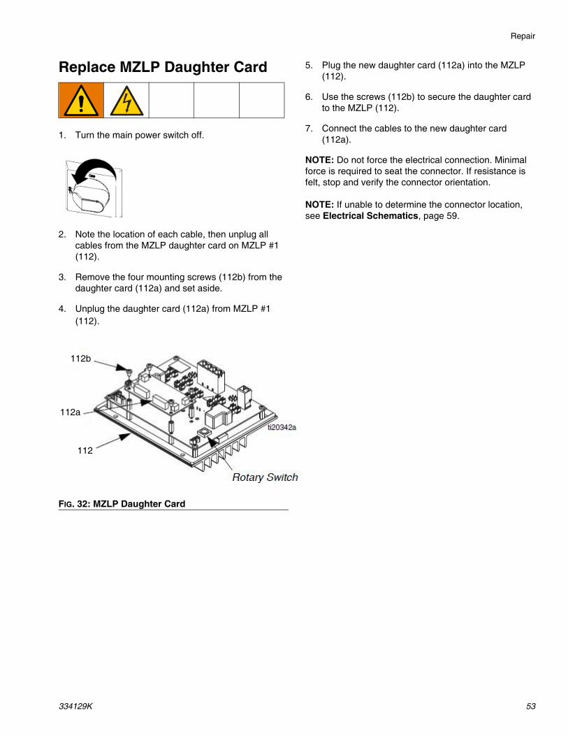
Replace MZLP Daughter Card
1. Turn the main power switch off.
2. Note the location of each cable, then unplug all cables from the MZLP daughter card on MZLP #1 (112).
3. Remove the four mounting screws (112b) from the daughter card (112a) and set aside.
4. Unplug the daughter card (112a) from MZLP #1 (112).
5. Plug the new daughter card (112a) into the MZLP (112).
6. Use the screws (112b) to secure the daughter card to the MZLP (112).
7. Connect the cables to the new daughter card (112a).
NOTE: Do not force the electrical connection. Minimal force is required to seat the connector. If resistance is felt, stop and verify the connector orientation.
NOTE: If unable to determine the connector location, see Electrical Schematics, page 59.
FIG. 32: MZLP Daughter Card
112b
112a
112
Repair
54 334129K
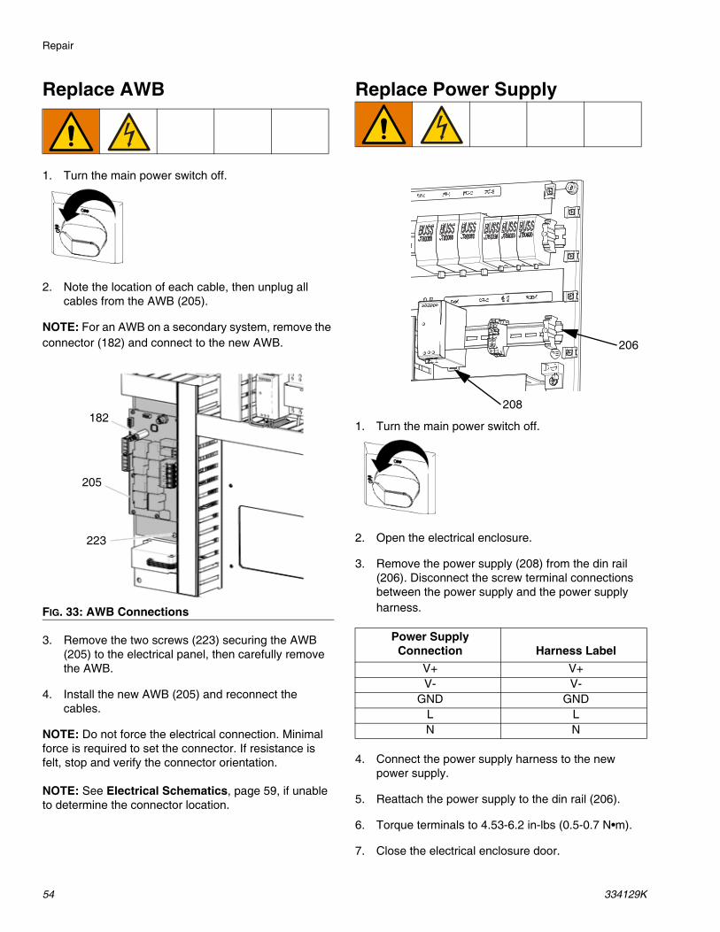
Replace AWB
1. Turn the main power switch off.
2. Note the location of each cable, then unplug all cables from the AWB (205).
NOTE: For an AWB on a secondary system, remove the connector (182) and connect to the new AWB.
3. Remove the two screws (223) securing the AWB (205) to the electrical panel, then carefully remove the AWB.
4. Install the new AWB (205) and reconnect the cables.
NOTE: Do not force the electrical connection. Minimal force is required to set the connector. If resistance is felt, stop and verify the connector orientation.
NOTE: See Electrical Schematics, page 59, if unable to determine the connector location.
Replace Power Supply
1. Turn the main power switch off.
2. Open the electrical enclosure.
3. Remove the power supply (208) from the din rail (206). Disconnect the screw terminal connections between the power supply and the power supply harness.
4. Connect the power supply harness to the new power supply.
5. Reattach the power supply to the din rail (206).
6. Torque terminals to 4.53-6.2 in-lbs (0.5-0.7 N•m).
7. Close the electrical enclosure door.
FIG. 33: AWB Connections
182
205
223
Power Supply Connection Harness Label
V+ V+V- V-
GND GNDL LN N
206
208
Repair
334129K 55
Replace Fan
1. Turn the main power switch off.
2. Disconnect the plug from the power outlet or turn off the circuit breaker for incoming power.
3. Open the electrical enclosure door.
4. Remove the connector from the J7 connector on the AWB board. Remove the red (+) and black (-) fan wires from the connector.
5. Cut any cable ties between the end of the fan wires to the fan (136).
6. Remove the screws (141), grill (137), four nuts (139), rear fan grill (138), and fan (136).
7. Mount the new fan (136), rear fan grill (138), and nuts (139) on the grill (137) with the arrow pointing toward the grill (137).
8. Tie down the fan wires onto the tie down locations on the grill (137) using cable zip ties.
9. Route the fan wires into the electrical enclosure. Connect the red and black fan wires to the J7 con-nector. Reconnect the J7 connector to the AWB. Use cable ties to secure the fan wires to other cables in the electrical enclosure.
NOTE: To prevent fan errors on the ADM, remove the excess slack and ensure that the cabling and zip ties do not contact the fan blades.
10. Reinstall the fan grill (137) and close the electrical enclosure.
J7
141
137136138139
Repair
56 334129K
Replace Transformer
See FIG. 34, page 57.
1. Turn the main power switch off.
2. Open the electrical enclosure door.
3. Disconnect the incoming power harness (234) from the top of the transformer (235).
4. Disconnect the transformer (235) output power har-ness wires (CR2-W1, -W2, -W3, -W4) from CR2.
5. Disconnect the transformer (235) ground wire from the back panel ground lug.
6. Disconnect the red (+) and black (-) wire of the fan from pins 4 and 3 of the J7 connector on the AWB (205). Disconnect the J7 connector from the AWB.
7. Cut the wire zip ties securing the fan wires.
8. Remove the flanged nuts (N) and transformer (235) from the back panel (201).
9. Install the transformer (235) onto mounting studs on the back panel (201) and secure with flanged nuts (N).
10. Insert the thermal sensor connector from the trans-former (235) onto the J7 connector on the AWB (205).
11. Reconnect the red (+) wire from the fan into pin 4 and the black (-) wire into pin 3 of the J7 connector.
12. Install the transformer (235) ground wire onto the ground lug of the back panel (201).
13. Connect the transformer output power harness (234) to the power terminal connections. Torque to 25–27 in-lbs (2.8–3.1 N•m).
Table 11 Transformer Output Power Harness Connections
14. Install the incoming power harness (234) to the top of the transformer in the voltage port specified on the machine serial number label.
15. Verify all electrical connections, including earth grounds, are complete and tight. All connections and plugs must be connected prior to applying power.
16. Close the electrical control panel door.
17. Apply power to the machine. Turn on the main power switch.
FIG. 34: Inside of Electrical Control Enclosure201
N
235
234
Z
J7
205
CR-2
G
Repair
58 334129K
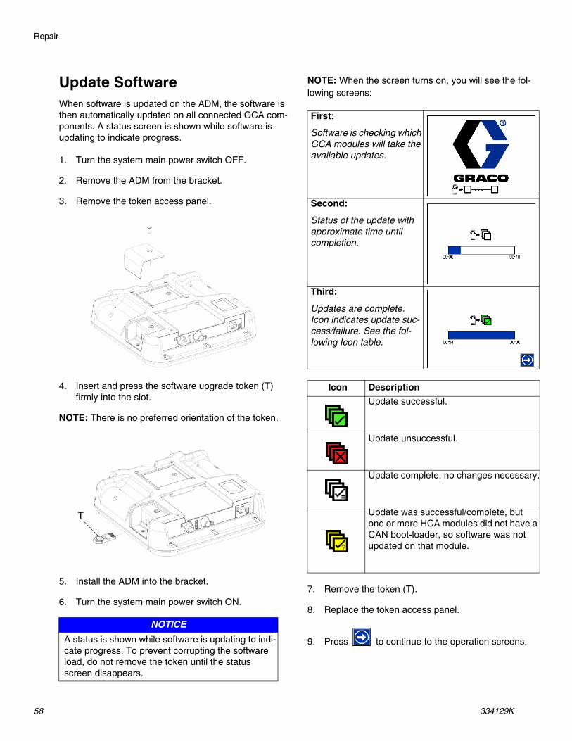
Update SoftwareWhen software is updated on the ADM, the software is then automatically updated on all connected GCA com-ponents. A status screen is shown while software is updating to indicate progress.
1. Turn the system main power switch OFF.
2. Remove the ADM from the bracket.
3. Remove the token access panel.
4. Insert and press the software upgrade token (T) firmly into the slot.
NOTE: There is no preferred orientation of the token.
5. Install the ADM into the bracket.
6. Turn the system main power switch ON.
NOTE: When the screen turns on, you will see the fol-lowing screens:
7. Remove the token (T).
8. Replace the token access panel.
9. Press to continue to the operation screens.
NOTICEA status is shown while software is updating to indi-cate progress. To prevent corrupting the software load, do not remove the token until the status screen disappears.
T
First:
Software is checking which GCA modules will take the available updates.
Second:
Status of the update with approximate time until completion.
Third:
Updates are complete. Icon indicates update suc-cess/failure. See the fol-lowing Icon table.
Icon DescriptionUpdate successful.
Update unsuccessful.
Update complete, no changes necessary.
Update was successful/complete, but one or more HCA modules did not have a CAN boot-loader, so software was not updated on that module.
Electrical Schematics
334129K 59
Electrical Schematics
230V, 3 Phase/60Hz
Electrical Schematics
60 334129K
400V, 3 Phase/50Hz
Electrical Schematics
334129K 61
400-600VV, 3 Phase/60Hz
Electrical Schematics
62 334129K
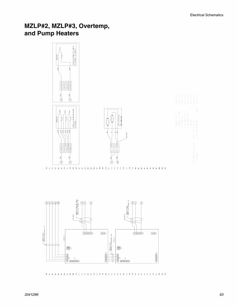
AWB and MZLP#1
ARELEASED A257M
Z090146
06/24/14
BSEE ECO
Z090616
07/23/14
CSEE ECO
Z091443
08/26/14
DSEE SHEETS 1,2,3
Z092531
10/17/14
ESEE SHEETS 1 AND 2.
Z093615
12/04/14
FSEE SHEET 1
Z095498
23MAR15
GSEE SHEET 1
Z097266
02JU
N15
HREVISED SHEET3
Z098180
30JU
N15
JSEE SHEET 1
Z104520
17MAR16
KREVISED SHEETS 2,3, & 4
Z106725
06/16/16
J5 J6
J7
J8J9
J4
J3
J2
CAN
200
201
202
203
204
205
206
207
208
209
210
211
212
213
214
215
216
217
218
219
220
221
222
223
224
225
226
227
228
229
230
231
232
233
234
235
236
237
238
239
240
250
251
252
253
254
255
256
257
258
259
260
261
262
263
264
265
266
267
268
269
270
271
272
273
274
275
276
277
278
279
280
281
282
283
284
285
286
287
288
289
290
J1
AWB-1
24+
GND
NL
EGND
- N L +
PS-1
129
130
131
265
266
267
268
332
330
329
122
125
ENCLOSURE FAN
(FAN-2)
127421
110
109
115
114
372
374
220
221
222
223
315
313
312
238
237
236
235
234
300
301
302
303
304
281
282
283
284
285
MOTOR-UP
MOTOR-DN
SOL-1
PX-LOW
PX-EMPTY
PUMP-RTD
PLATEN-RTD
54321
G 3 2 1 G 3 2 1
1290
1300
1310
1220
1250
2610
2620
J16J14 J15
J7
J6J5
J1
J2
MZTCM-1
J13J12
L1 L3 G L3 L2 L1
54321432143
21
54
32
1
54
32
1654321
43
21
4321
43
21
1140
1150
1090
1100
W1
W2
W3
W4
G
2270
2320
2790
RED
2770
2720
2710
2700
2670
2680
2650
2640
2560
2570
- N L +
+V
-V
N
L
GND
132
1320
HARNESS 17A559
AWB-1-J8 TO MZTCM-1-J6
BLACK
YELLOW
YELLOW
RED
- +
HARNESS 17A543
AWB-1-J6 TO MZTCM-1-J2
HARNESS 17A544 OR 17A545
AWB-1-J5 TO MZTCM-2-J2
AWB-1-J5 TO MZTCM-3-J2
HARNESS 17A543
MZTCM-1-J2 TO AWB-1-J6
HARNESS 17A551
MZTCM-1-J1 TO TERM BLOCKS
HARNESS 17A557
MZTCM-1-J12 TO SOL-1
HARNESS 127511
MZTCM-1-J3 TO MZTCM-2-J6
J3
HARNESS 24V745
HARNESS 17A559
MZTCM-1-J6 TO AWB-1-J8
HARNESS 17A553
MZTCM-1-J7 TO SSR-1 AND CR-1
BLUE
RED
RED
BLUE
HARNESS 17A555
2730
2740
RED
BLUE
RED
WHITE
WHITE
2760
355
358
RED
REDHARNESS 17B768
HARNESS 17A552
18 AWG
10 AWG
10 AWG
10 AWG
18 AWG
12 AWG
10 AWG
22 AWG
22 AWG
22 AWG
Electrical Schematics
334129K 63
MZLP#2, MZLP#3, Overtemp, and Pump Heaters
ARELEASED A257M
Z090146
06/24/14
BSEE ECO
Z090616
07/23/14
CSEE ECO
Z091443
08/26/14
DSEE SHEETS 1,2,3
Z092531
10/17/14
ESEE SHEETS 1 AND 2.
Z093615
12/04/14
FSEE SHEET 1
Z095498
23MAR15
GREVISED PUMP WIRING
Z097266
02JU
N15
HREVISED SHEET 3
Z098180
30JU
N15
JSEE SHEET 1
Z104520
17MAR16
KREVISED SHEETS 2,3, & 4
Z106725
06/16/16
300
301
302
303
304
305
306
307
308
309
310
311
312
313
314
315
316
317
318
319
320
321
322
323
324
325
326
327
328
329
330
331
332
333
334
335
336
337
338
339
340
350
351
352
353
354
355
356
357
358
359
360
361
362
363
364
365
366
367
368
369
370
371
372
373
374
375
376
377
378
379
380
381
382
383
384
385
386
387
388
389
390
B3
T3
262
261
2 240V/1200W TOTAL
2610
2620
215
217
218
254
253
252
251
250
215
217
218
MZTCM-3
MZTCM-2
J74
3
21J7
J6
J5
J1
J2
L3L1GL3L2L1
54
32
1
54
32
1 6 5 4 3 2 1
43
21
J3
HARNESS 127511
MZTCM-2-J3 TO MZTCM-3-J6
J6
J5
54
32
1 6 5 4 3 2 1
J1
J2
L3L1GL3L2L1
54
32
1J3
HARNESS 127511
MZTCM-2-J6 TO MZTCM-1J3
HARNESS 17A544 OR 17A545
MZTCM-2-J2 TO AWB-1-J5
HARNESS 17A545
MZTCM-3-J2 TO AWB-1-J5
B1
T1
321
2740
275
274
2730
2740
2731
2730
2730
2731
2732
2740
2731
2732
2732
PLATEN
PUMP
PUMP
TYPICALL ALL TOF200 AND TOFP20's
OVERTEMPS
ALL VOLTAGES
2740
275
274
2730
2740
2730
2730
2731
2732
2740
PLATEN
TYPICALL OF TOFP20's WITH CODE D
OVERTEMP
AT SELECTION 7. ALL VOLTAGES
10 AWG
10 AWG
16 AWG
Electrical Schematics
64 334129K
MZLP Zones
A RELEASED A257M Z090146 06/24/14
B SEE ECO Z090616 07/23/14
C SEE ECO Z091443 08/26/14
D SEE SHEETS 1,2,3 Z092531 10/17/14
E SEE SHEETS 1 AND 2. Z093615 12/04/14
F SEE SHEET 1 Z095498 23MAR15
G SEE SHEET 1 Z097266 02JUN15
H REVISED SHEET 3 Z098180 30JUN15
J SEE SHEET 1 Z104520 17MAR16
K REVISED SHEETS 2,3, & 4 Z106725 06/16/16
400
401
402
403
404
405
406
407
408
409
410
411
412
413
414
415
416
417
418
419
420
421
422
423
424
425
426
427
428
429
430
431
432
433
434
435
436
437
438
439
440
MZTCM-1
J8
J9
C
D
E
F
G
H
J
M
L
K
A
B
TYPICAL ZONE PIN OUTCONNECTOR PIN # FUNCTION
MZTCM-1
MZTCM-1 J9
A ZONE 1,L2B SHIELDC ZONE 2,L1D ZONE 2,L2E JUMPERF ZONE 1,STARTG ZONE 1,RTDH JUMPERJ ZONE 1,L1K RTD EXCITEL ZONE 2,STARTM ZONE 2,RTD
MZTCM-1 J8
A ZONE 3,L2B SHIELDC ZONE 4,L1D ZONE 4,L2E JUMPERF ZONE 3,STARTG ZONE 3,RTDH JUMPERJ ZONE 3,L1K RTD EXCITEL ZONE 4,STARTM ZONE 4,RTD
MZTCM-2
MZTCM-2 J9
A ZONE 5,L2B SHIELDC ZONE 6,L1D ZONE 6,L2E JUMPERF ZONE 5, STARTG ZONE 5,RTDH JUMPERJ ZONE 5,L1K RTD EXCITEL ZONE 6,STARTM ZONE 6,RTD
MZTCM-2 J8
A ZONE 7,L2B SHIELDC ZONE 8,L1D ZONE 8,L2E JUMPERF ZONE 7,STARTG ZONE 7,RTDH JUMPERJ ZONE 7,L1K RTD EXCITEL ZONE 8,STARTM ZONE 8,RTD
MZTCM-3
MZTCM-3 J9
A ZONE 9,L2B SHIELDC ZONE 10,L1D ZONE 10,L2E JUMPERF ZONE 9,STARTG ZONE 9,RTDH JUMPERJ ZONE 9,L1K RTD EXCITEL ZONE 10,STARTM ZONE 10,RTD
MZTCM-3 J8
A ZONE 11,L2B SHIELDC ZONE 12,L1D ZONE 12,L2E JUMPERF ZONE 11,STARTG ZONE 11,RTDH JUMPERJ ZONE 11,L1K RTD EXCITEL ZONE 12,STARTM ZONE 12,RTD
ZONE-1-RTD
ZONE-2-RTD
ZONE-1-START
ZONE-2-START
ZONE-2-HEAT
ZONE-1-HEAT
A
J
C
D
G
F
K
L
M
E
H
B
TYPICAL ZONE PIN OUT
MZTCM-2
MZTCM-3
J8
J9
J8
J9
21
65
109
43
87
1211
Parts
334129K 65
PartsTherm-O-Flow 20 Supply Unit
23
2524
8
3
9
10
11
1213
20 21 1217
18
19 13ti25320a
12
15
11
22
1
26
6
5
27
4
1416
18
17
2
7
Parts
66 334129K
Therm-O-Flow 20 Supply UnitRef Part Description Qty1 --- Frame 12 24W870 KIT, air control; see Air Control
Assembly, page 671
3 --- CONTROL, electrical (not used with air control only systems)
1
4 --- MODULE, pump; see Pump Mod-ules, page 75.
1
5 --- PLATEN; see Heated Platens, page 84
1
6 C31065 SEAL 17 24W812 ADM 18 24W589 KIT, light tower (optional); see
630 127690 FITTING, adapter, 5/16 in tube x 1/4 in tube
1
631 054130 HOSE, tubing; 1/4 in OD;17 ft (5 m)
1
632 --- LUBRICANT, high temperature, thermal
1
633 150286 ADAPTER 1
Ref Part Description Qty
Platen Model Plate (601) Description Qty. Element Resistance24V742 Standard Finned 1 28.8 ohms +3/-424V743 Smooth Bottom 1 28.8 ohms +3/-4
Accessories and Kits
86 334129K
Accessories and KitsWiper Kits
Applicators and Dispense Valves
Air-Operated Heated Dispense Valves
CGM Installation Kit, 25C994This kit enables controlling logic, such as a robot control-ler or PLC continuously monitoring data from the Therm-O-Flow system, as well as optionally controlling the system accordingly. Refer to manual 3A5186 for details on the interface. When ordering this kit, select and order the correct communication gateway module (CGM) that matches the field bus being used. The following CGM modules are available for the Therm-O-Flow sys-tem.
Flow Control and Manifolds
Accessory Extension CablesUse to connect fluid control devices and heated hoses to the electrical control enclosure.
Light Tower Kit, 24W589
Tie Rod KitsUse to retrofit Check-Mate 800 Displacement Pump to an existing Therm-O-Flow system.
Part No. DescriptionC31065 Seal Kit
Part No. Description249515 Manual Gun, Top Feed, 240V249514 Manual Gun, Bottom Feed, 240V249513 Manual Gun, Top Feed, Electric Switch,
240V249512 Manual Gun, Bottom Feed, Electric Switch,
240V
Part No. Description243694 Automatic Dispense Valve, 240V,
Part No. DescriptionConnect between controller and heated hose129300 15 ft, 12 pin to 12 pin129301 25 ft, 12 pin to 12 pinConnect between controller and heated accessory129302 15 ft, 12 pin to 8 pin129303 25 ft, 12 pin to 8 pinConnect between controller and heated devices129703 25 ft, 12 pin to (2) 8 pin129304 50 ft, 12 pin to (2) 8 pin
Part No. Description24V750 Bulldog® and Senator® Tie Rod Kit; see
manual 33413124V754 NXT® Tie Rod Kit; see manual 334132
Accessories and Kits
334129K 87
Heated Hoses and Fittings
Hose Diameter
-6(9/16 in -18 JIC)
-8(3/4 in -16 JIC)
-10(7/8 in -14 JIC)
-12(1-1/16 in -12 JIC)
-16(1-5/16 in -12 JIC)
-20(1-5/8 in -12 JIC)
Hose Length3 ft (1.5 m) None None None 15C586 None None6 ft (1.8 m) None 115902 115875 None 115884 None10 ft (3 m) 16J875 115873 115876 115880 115885 11782115 ft (4.6 m) None 115874 17J656 115881 115886 11782220 ft (6 m) None None 115878 115882 115887 None25 ft (7.6 m) None None 115879 115883 115888 None30 ft (9 m) None None 121200 None None NonePump FittingsTOF 20/200 PUMP 1-11 1/2 DUAL OUTLET ADD 120263
1. Disconnect the plug from the power outlet or turn off the circuit breaker for incoming power.
2. Place the grounding wrist strap (7) over your wrist and secure the other end to a grounded surface.
3. Set the kit’s MZLP (1) rotary switch to “2” on a pri-mary system or “6” on a secondary system.
4. Remove the screws (B), the plate (A), and the gas-ket (C) from the system. Use the screws (2) to install the MZLP (1) onto the system as shown.
NOTE: The new MZLP (1) will be refereed to as MZLP2, and the original MZLP that came with the system will be referred to as MZLP 1.
5. Open the electrical enclosure door.
NOTE: Do not force the electrical connection. Minimal force is required to seat the connector. If resistance is felt, stop, and verify the connector orientation.
6. Connect the cable (4) to the J3 connector on MZLP 1 and the J6 connector on MZLP 2.
7. Connect the power harness (6) to the MZLP 2 J2 connector and the J5 connector on the AWB. Install the jumper (5) on the MZLP 2 J5 connector.
8. Use fittings and hoses that meet your hose routing needs. See Accessories and Kits, page 86.
9. To ensure your system has the latest software, insert the token (8) into the ADM. See Update Soft-ware, page 58.
Accessories and Kits
334129K 91
12 Channel Upgrade Kit, 24V756Use this kit to upgrade an 8 channel system to a 12 channel system.
1. Disconnect the plug from the power outlet or turn off the circuit breaker for incoming power.
2. Place the grounding wrist strap (7) over your wrist and secure the other end to a grounded surface.
3. Set the kit’s MZLP (1) rotary switch to “3” on a pri-mary system or “7” on a secondary system.
4. Remove the screws (B), plate (A), and the gasket (C) from the system. Use the screws (2) to install the MZLP (1) on to the system as shown.
NOTE: The new MZLP (1) will be referred to as MZLP 3, and the other two that came with the system will be referred to as MZLP 1 and MZLP 2.
5. Open the electrical enclosure door.
NOTE: Do not force the electrical connection. Minimal force is required to seat the connector. If resistance is felt, stop, and verify the connector orientation.
6. Connect the cable (4) to the J3 connector on MZLP 2 and the J6 connector on MZLP (1). Remove the existing power cable from MZLP 2 J2 and AWB J5 connector.
7. Connect the power harness (6) to MZLP 2 and the MZLP 3 J2 connector and the J5 connector on the AWB.
8. See Install Heated Hose, page 17, to connect a heated hose or fluid control device.
9. To ensure your system has the latest software, insert the token (8) into the ADM. See Update Soft-ware, page 58.
Appendix A - ADM
334129K 93
Appendix A - ADM
General OperationADM PowerThe ADM automatically turns on when the main power switch is turned on.
Screen NavigationTo switch between the Setup and Operation screens,
press . Use the keypad to navigate between screens.
Enable, Disable Heating SystemTo enable or disable the entire heating system, press
. To set which channels are active when the heat-ing system is enabled, use the Heat-A and Heat-B Setup screens.
Appendix A - ADM
94 334129K
Icons
Screen IconsThese are frequently used icons on the screens. The following descriptions explain what each icon represents.
Softkey IconsThe following icons appear in the ADM, directly to the left or right of the soft key which activates that operation.
Icon DescriptionPrimary System= A
Secondary System = B
Heating Disabled
Warm Up, Actual tempera-ture is outside of Target Temperature
Reached Target Tempera-ture
Hose
Gun
Manifold
PGM
Flow Meter
Pressure Regulator
Other
Advisory. See Error Codes for more informa-tion.Deviation. SeeError Codes for more informa-tion.Alarm. See Error Codes for more information.
Icon DescriptionPause Material Tracking
Continue Material Tracking
Pump Ready
Setback
Reset Cycle Counter (press and hold)
Add or edit event
Accept schedule
Crossover for Tandem Systems
Erase or cancel schedule
Cancel
Clear
Schedule Event On/Off
Heat On/Off
Appendix A - ADM
334129K 95
Operation Screens
HomeThis screen shows the temperature state of the system and material usage.
NOTE: If present, secondary systems will be shown on the home page.
Heat AThis screen shows the target and actual temperatures for all zones on the system.
NOTE: The Heat-B screen shows information for an optional secondary system.
EventsThe Events screens store a maximum of 200 events. The events list can be downloaded in the USB logs. See Appendix B - USB Data, page 101.
Color A and B Zone StatusWhite OffGreen On and at setpoint tem-
peratureRed Outside of alarm rangeYellow Outside of advisory rangeGreen/Yellow Flashing Warmup
Tracked EventsCustom Language DownloadedCustom Language UploadedFill Valve ClosedFill Valve OpenHeat OffHeat OnLogs DownloadedPump Cycles Total ResetPump OffPump OnRed Stop Button PressedSetup Value ChangedSystem Power OffSystem Power OnSystem Settings DownloadedSystem Settings UploadedUSB DisabledUSB Drive InsertedUSB Drive RemovedUser Maintenance Count Reset
Appendix A - ADM
96 334129K
Errors
The Errors screens store a maximum of 200 errors. See Error Codes. Download the errors list in the USB logs. See Appendix B - USB Data, page 101.
Diagnostic - A
This screen shows details of various items to aid in troubleshooting the system. This screen can be hidden by de-selecting “Enable Diagnostics Screen” on the System 3 screen. The flow rate updates every 15–20 seconds with average flow rate over the last 15–20 seconds.
NOTE: Diagnostic - B shows information for an optional secondary system.
The following information is displayed.
CAN: 24 VDC power supply voltage reading (18-28 VDC)
DI: System Digital Inputs0: Drum Empty1: Drum Low2: Pump Cycle Switch Up3: Pump Cycle Switch Down
DO: System Digital Outputs0: Pump Solenoid1: Not Used2: Not Used3: Not Used
ISO DI: Customer Digital InputsSee Connect PLC (Hard Wired Interface Version), page 25.
ISO DO: Customer Digital OutputsSee Connect PLC (Hard Wired Interface Version), page 25.
Fan: Current to fan
Heat Soak: Set time for platen to heat after the platen has reached set temperature.
Life Cycles: Total number of pump cycles over the life of the system.
MZLP 1: Temperature on MZLP 1.
• 32-160°F (0-71°C)
Pump Sol: Current draw of pump solenoid.
• (0 mA - off)• (150-250 mA - on)
Pump CPM: Pump cycles per minute.
USB DL%: Percentage complete, only applies when downloading USB data. 5 downloads will occur.
Weight: Weight of material dispensed over the life of the system.
XFMRTemp: Temperature of the transformer tempera-ture sensor.
Diagnostic DataA Current DrawB RTD ReadingC Duty Cycle
Appendix A - ADM
334129K 97
Setup ScreensNOTE: It is important to set all settings in the System screens correctly to ensure optimal system perfor-mance.
PasswordIf the password is not “0000”, the password must be entered to access the setup screens.
System 1
External Pump Control: Enable feature that automati-cally turns on and off the pump when using a handhelddispense gun with an integrated trigger switch.
Enable Diagnostic Screen: Choose whether to showthe Diagnostic screen.
Enable Temp. Adjustments: Allows temperature ad-justments on the Heat-A and Heat-B Run screens.
Enable Pump Autostart: Automatically turns the pumpon after reaching setpoint temperature and heat soak iscomplete.
Enable Tandem System: Enable all secondary systemADM screens.
Heat Soak: Time for to preheat after all zones havereached their target temperatures. Pump cannot turn onuntil timer is complete. The heat soak is a user-definedtime.
• Range: 1-120 minutes• 0 disables heat soak
Pump Inactive Timeout: If no pump movement is detected or either pump for (x) amount of time, all heated zones enter setback mode. After an additional amount of time (x), the heat will turn off.
• (x) Range: 0-120 minutes• 0 disables heat soak
System 2
Enter low and high temperatures for an alarm or warning to occur.
Advanced 1
Language: Language displayed on the screen.
Date Format: Choose the format of the date.
Date: Set the date.
Time: Set the time.
Appendix A - ADM
98 334129K
Enter Password: If not “0000”, the Setup screens will be password protected.
Screen Saver: The screen will go black after the set amount of time.
Silent Mode: Disable ADM sounds.
Advanced 2
Temperature Units: Units of measure for displayed temperatures.
Mass Units: Units of measure for mass.
Specific Gravity: Required to convert the volume dis-pensed to mass dispensed for tracking the total weight and flow rate. When the specific gravity value is popu-lated, the total mass dispense since the last total weight reset is shown on the Home screen and the mass flow rate is shown on the Diagnostic screen.
NOTE: If the Specific Gravity is set to zero, the Home screen will display a cycle counter instead of grams or pounds.
Heat Rate Option: Control option where the user can select the rate at which heat is applied to all zones enabled or selected. Three options are available, Nor-mal (default), Fast, and Slow. The Warm Up system time would be shortest for the Fast option, then the Nor-mal, and longest if the Slow option is selected. If the material set temperatures are less than 200° F (93° C), the Slow option may be best for the application.
Advanced 3
Appendix A - ADM
334129K 99
Disable USB Downloads/Uploads: Disables use of the USB for downloading and uploading.
Disable USB Log Errors: When disabled, the system will not warn the user when logs are full. If the logs are full, the oldest data will be overwritten.
Download Depth: Last _ Days: The USB download will provide data as old as the number of days entered. Old data may be in memory but will not be downloaded if older than the number of days entered.
Advanced 4 and 5
Advanced 4 screen shows the part number and version of each installed software module on a primary unit and Advanced 5 shows each module on a secondary unit.
Heat - A
Use these screens to set target and setback temperatures for the pump, platen, and zones. Select which system needs to use the heated accessory.
Zone Types:
• Hose• Gun• PGM• Flowmeter• Pressure Regulator• Manifold• Other
NOTE: To ensure accurate hose and gun temperatures, set hose as zone 1, 3, 5, 7, 9, or 11 when connected to MZLP and a heated hose.
Appendix A - ADM
100 334129K
Maintenance - A
The system will notify the user at the set interval that maintenance is required. The fields in boxes can be edited by the user. “Due” and “Current” are both the number of cycles since the last reset. “Interval” is the set number of cycles between maintenance notifications. “Lifetime” is the number of cycles in the lifetime of the system.
NOTE: The lifetime cycle count will only be reset if the ADM is replaced.
Schedule
Use this screen to set times that the system will automatically enable and disable heating. See Schedule, page 35.
Gateway 1 and 2If the Therm-O-Flow system has a communication gate-way module (CGM) installed, an additional “Gateway” chapter containing 1 or 2 pages will be available in the setup screens. These pages enable the user to set the CGM IP or device address, configure the field bus proto-col selections, and enable the user to view the mapping information programmed into the CGM module. The screens shown below illustrate the 2 pages provided if an Ethernet I/P CGM module is installed. Refer to man-ual 3A5186 for information on mapping and the screens available for the other field bus options.
Appendix B - USB Data
334129K 101
Appendix B - USB DataThe system can store 250,000 entries in its logs and the system adds a new entry to the logs every 15 seconds. This means the system stores 1041 hours of system operation data, or 43 days of around-the-clock operation. Once full, the system will overwrite the oldest data.
NOTE: To prevent losing any data, never go more than 43 days without downloading the logs.
Download
NOTE: The event log, error log, system settings, and system language files are all downloaded in this proce-dure.
1. Insert USB flash drive into USB port.
NOTE: Flash drive must be 8 GB or smaller.
2. The menu bar and USB indicator lights indicate that the USB is downloading files. Wait for USB activity to complete. A pop-up will be present until the trans-fer is complete if it is not acknowledged.
NOTE: If the pop-up screen does not appear, the flash drive is not compatible with the ADM. Try a different flash drive.
NOTE: The system can log up to 45 mb of additional data per week, depending on system operation.
Access FilesAll files downloaded from the USB are put in a DOWN-LOAD folder on the stick drive. For example: “E:\GRACO\12345678\DOWNLOAD\”. The 8-digit numeric folder name matches the 8-digit ADM serial number, which is located on the back of the ADM. When downloading from multiple ADMs, there will be one sub-folder in the GRACO folder for each ADM.
The log files should be opened in a spreadsheet pro-gram.
NOTE: If emailing the files, zip (compress) them to mini-mize file size.
UploadUpload a system configuration file and/or a custom lan-guage file. See System Settings File, page 102 or Sys-tem Language File, page 103.
1. If necessary, follow the Download Instructions, page 101, to automatically generate the proper folder structure on the USB flash drive.
2. Insert USB flash drive into USB port of computer.
3. The USB flash drive window automatically opens. If it does not, open USB flash drive from within Win-dows Explorer.
4. Open Graco folder.
5. Open system folder. If working with more than one system, there will be more than one folder within the Graco folder. Each folder is labeled with the corre-sponding serial number of the ADM. (The serial number is on the back of the module.)
6. If installing the system settings file, place SET-TINGS.TXT file into UPLOAD folder.
7. If installing the custom language file, place DISP-TEXT.TXT file into UPLOAD folder.
8. Remove USB flash drive from computer.
9. Install USB flash drive into Therm-O-Flow system USB port.
10. The menu bar and USB indicator lights indicate that the USB is uploading files. Wait for USB activity to complete.
NOTICEUploading an edited system configuration file can damage the system. Never put a modified SET-TINGS.TXT file in the UPLOAD folder on the flash drive.
Appendix B - USB Data
102 334129K
11. Remove USB flash drive from USB port.
NOTE: If a custom language file was installed, users can now select the new language from the Language drop-down menu.
NOTE: If the SETTINGS.TXT or DISPTEXT.TXT files remain in the UPLOAD folder, they will be uploaded every time the USB drive is inserted into the corre-sponding ADM. To avoid unintentionally overwriting sys-tem settings, delete the files from the UPLOAD folders on the USB drive after the upload is complete.
USB LogsDuring operation, the Therm-O-Flow stores system and performance related information to memory in the form of log files. The Therm-O-Flow maintains the events, data, GCA, Black Box, and Diagnostics logs. Follow the Download Procedure, page 101, to retrieve log files.
Events LogThe event log (1-EVENT.CSV) maintains a record of the last 175,000 events. Each event record in the log file contains the date and time the event occurred, the event type, event code, and event description.
Data LogThe data log (2-DATA.CSV) tracks the setpoint and actual temperatures every 15 seconds. This log can store up to 250,000 lines of data.
The system stores 1041 hours of system operation data, or 43 days of around-the-clock operation. Once full, the system will overwrite the oldest data.
Change LogThe change log (3–CHANGE.CSV) tracks the changes to setpoint and setback temperatures.
GCA LogThis log (4-GCA.CSV) lists the installed GCA modules and their respective software versions.
Black Box, Diagnostics LogThese logs (5-BLACKB.CSV, 6-DIAGN.CSV) are designed to provide useful information to Graco when calling for technical assistance.
System Settings File
The system configuration settings file name is SET-TINGS.TXT and is stored in the DOWNLOAD folder.
A system configuration settings file automatically down-loads each time a USB flash drive is inserted. Use this file to back up system settings for future recovery or to easily replicate settings across multiple Therm-O-Flow systems. Refer to the Upload Instructions, page 101, for how to use this file.
It is recommended to retrieve the SETTINGS.TXT file after all system settings are set as desired. Store the file for future use as a backup in case the settings are changed and need to be quickly changed back to the desired setup.
NOTE: System settings may not be compatible between different versions of the Therm-O-Flow software.
NOTICEUploading an edited system configuration file can damage the system. Never put a modified SETTNGS.TXT file in the UPLOAD folder on the flash drive.
Appendix B - USB Data
334129K 103
System Language FileThe system language file name is DISPTEXT.TXT and is stored in the DOWNLOAD folder.
A system language file automatically downloads each time a USB flash drive is inserted. If desired, use this file to create a user-defined set of custom language strings to be displayed within the ADM.
The system is able to display the following Unicode characters. For characters outside of this set, the sys-tem will display the Unicode replacement character, which appears as a white question mark inside of a black diamond.
• U+0020 - U+007E (Basic Latin)
• U+00A1 - U+00FF (Latin-1 Supplement)
• U+0100 - U+017F (Latin Extended-A)
• U+0386 - U+03CE (Greek)
• U+0400 - U+045F (Cyrillic)
Create Custom Language StringsThe custom language file is a tab-delimited text file that contains two columns. The first column consists of a list of strings in the language selected at the time of down-load. The second column can be used to enter the cus-tom language strings. If a custom language was previously installed, this column contains the custom strings. Otherwise the second column is blank.
Modify the second column of the custom language file as needed and then follow the Upload Instructions, page 101, to install the file.
The format of the custom language file is critical. The following rules must be followed in order for the installa-tion process to succeed.
1. The file name must be DISPTEXT.TXT.
2. The file format must be a tab-delimited text file using Unicode (UTF-16) character representation.
3. The file must contain only two columns, with col-umns separated by a single tab character.
4. Do not add or remove rows to the file.
5. Do not change the order of the rows.
6. Define a custom string for each row in the second column.
Dimensions
104 334129K
DimensionsRam Mounting and Clearance
Ain. (mm)
Bin. (mm)
Cin. (mm)
Din. (mm)
Ein. (mm)
Fin. (mm)
Gin. (mm)
Jin. (mm)
Kin. (mm)
Lin. (mm)
Min. (mm)
Pin. (mm)
40 (1016)
28(711)
36(914)
22(558)
24(609)
40.8 (1036)
29.7(754)
11(279)
6(152)
1(25.4)
60 (1524)
62 (1574)
Height (H) DimensionsFully Raised 74.3 in (1887 mm)Fully Lowered 57.3 in (1455 mm)
Dimensions
334129K 105
15:1
Ain. (mm)
Bin. (mm)
Din. (mm)
Ein. (mm)
Gin. (mm)
Kin. (mm)
Lin. (mm)
Min. (mm)
Nin. (mm)
Pin. (mm)
40 (1016)
28(711)
22(558)
24(609)
29.7(754)
6(152)
1(25.4)
48 (1219)
38.5 (977)
62 (1574)
Height (H) DimensionsFully Raised 73.5 in (1866 mm)Fully Lowered 56.5 in (1435 mm)
Technical Specifications
106 334129K
Technical Specifications
Therm-O-Flow 20 Hot Melt System
U.S. MetricAir inlet size 1/2 npsm(f)Air motor sound data See air motor instruction manual.Wetted Parts carbon steel, brass, chrome, zinc, nickel plating, stainless steel (304, 316,
440, and 17-4 PH), alloy steel, ductile iron, PTFEDisplacement Pump Effective AreaMerkur and NXT 1.24 in² 8 cm²President 0.884 in² 5.7 cm²Volume per CycleMerkur and NXT 11.7 in³ 192 cm³President 3.8 in³ 62.3 cm³Pump Cycles per 1 Gallon (3.8 liters)Merkur and NXT 21President 61Ram Maximum Input PressureMerkur and NXT 100 psi 0.7 MPa, 7 barPresident 100 psi 0.7 MPa, 7 barPresident 4.25 in 100 psi 0.7 MPa, 7 barMaximum Pump Operating TemperatureMerkur and NXT 400°F 204°CPresident 400°F 204°CPump Fluid Outlet SizeMerkur and NXT 1 in npt(f)President 1/2 in npt(f)Maximum Fluid Working Pressure23:1 2300 psi 15.9 MPa, 159 bar36:1 3000 psi 20.7 MPa, 207 bar70:1 3000 psi 20.7 MPa, 207 barPresident 4.25 in 1800 psi 12.6 MPa, 125 barMaximum Air Input Pressure (Pumps)23:1 100 psi 0.7 MPa, 7 bar36:1 82 psi 0.57 MPa, 5.7 bar70:1 43 psi 0.29 MPa, 2.9 barPresident 4.25 in 120 psi 0.8 MPa, 8.3 barPower RequirementsCompressed Air (typical) 25–50 scfmVoltage (as selected) 220/240 V, 3-phase, 50/60 Hz
Peak Consumption(includes drum melt grid, pump, and a 6kVa transformer for the 230 V hoses and accessories)Standard melt grid platen with Presi-dent pump
6.4 kVa
Standard melt grid platen with Merkur or NXT pump
8.7 kVa
Smooth melt grid platen with Presi-dent pump
6.4 kVa
Smooth melt grid platen with Merkur or NXT pump
8.7 kVa
Therm-O-Flow 20 Hot Melt System
All written and visual data contained in this document reflects the latest product information available at the time of publication. Graco reserves the right to make changes at any time without notice.
Original instructions. This manual contains English. MM 334129Graco Headquarters: Minneapolis
International Offices: Belgium, China, Japan, Korea
GRACO INC. AND SUBSIDIARIES • P.O. BOX 1441 • MINNEAPOLIS MN 55440-1441 • USACopyright 2016, Graco Inc. All Graco manufacturing locations are registered to ISO 9001.
www.graco.comRevision K, December 2017
Graco Standard WarrantyGraco warrants all equipment referenced in this document which is manufactured by Graco and bearing its name to be free from defects in material and workmanship on the date of sale to the original purchaser for use. With the exception of any special, extended, or limited warranty published by Graco, Graco will, for a period of twelve months from the date of sale, repair or replace any part of the equipment determined by Graco to be defective. This warranty applies only when the equipment is installed, operated and maintained in accordance with Graco’s written recommendations.
This warranty does not cover, and Graco shall not be liable for general wear and tear, or any malfunction, damage or wear caused by faulty installation, misapplication, abrasion, corrosion, inadequate or improper maintenance, negligence, accident, tampering, or substitution of non-Graco component parts. Nor shall Graco be liable for malfunction, damage or wear caused by the incompatibility of Graco equipment with structures, accessories, equipment or materials not supplied by Graco, or the improper design, manufacture, installation, operation or maintenance of structures, accessories, equipment or materials not supplied by Graco.
This warranty is conditioned upon the prepaid return of the equipment claimed to be defective to an authorized Graco distributor for verification of the claimed defect. If the claimed defect is verified, Graco will repair or replace free of charge any defective parts. The equipment will be returned to the original purchaser transportation prepaid. If inspection of the equipment does not disclose any defect in material or workmanship, repairs will be made at a reasonable charge, which charges may include the costs of parts, labor, and transportation.
THIS WARRANTY IS EXCLUSIVE, AND IS IN LIEU OF ANY OTHER WARRANTIES, EXPRESS OR IMPLIED, INCLUDING BUT NOT LIMITED TO WARRANTY OF MERCHANTABILITY OR WARRANTY OF FITNESS FOR A PARTICULAR PURPOSE.
Graco’s sole obligation and buyer’s sole remedy for any breach of warranty shall be as set forth above. The buyer agrees that no other remedy (including, but not limited to, incidental or consequential damages for lost profits, lost sales, injury to person or property, or any other incidental or consequential loss) shall be available. Any action for breach of warranty must be brought within two (2) years of the date of sale.
GRACO MAKES NO WARRANTY, AND DISCLAIMS ALL IMPLIED WARRANTIES OF MERCHANTABILITY AND FITNESS FOR A PARTICULAR PURPOSE, IN CONNECTION WITH ACCESSORIES, EQUIPMENT, MATERIALS OR COMPONENTS SOLD BUT NOT MANUFACTURED BY GRACO. These items sold, but not manufactured by Graco (such as electric motors, switches, hose, etc.), are subject to the warranty, if any, of their manufacturer. Graco will provide purchaser with reasonable assistance in making any claim for breach of these warranties.
In no event will Graco be liable for indirect, incidental, special or consequential damages resulting from Graco supplying equipment hereunder, or the furnishing, performance, or use of any products or other goods sold hereto, whether due to a breach of contract, breach of warranty, the negligence of Graco, or otherwise.
FOR GRACO CANADA CUSTOMERSThe Parties acknowledge that they have required that the present document, as well as all documents, notices and legal proceedings entered into, given or instituted pursuant hereto or relating directly or indirectly hereto, be drawn up in English. Les parties reconnaissent avoir convenu que la rédaction du présente document sera en Anglais, ainsi que tous documents, avis et procédures judiciaires exécutés, donnés ou intentés, à la suite de ou en rapport, directement ou indirectement, avec les procédures concernées.
Graco InformationSealant and Adhesive Dispensing Equipment
For the latest information about Graco products, visit www.graco.com.For patent information, see www.graco.com/patents.
TO PLACE AN ORDER, contact your Graco distributor, go to www.graco.com and select “Where to Buy” in the top blue bar, or call to find the nearest distributor.
If calling from the US: 800-746-1334If calling from outside the US: 0-1-330-966-3000