88
GSE Model 370 & Model 375 Precision Counting Scale Technical Reference Manual Version 1.0

GSE Model 370 & Model 375
Precision Counting Scale
Technical Reference Manual Version 1.0


Model 370 & Model 375
Technical Reference Manual
Version 1.0

GSE 370 / 375 Precision Parts Counter Technical Reference Manual Copyright © 2004 GSE Scale Systems. All rights reserved. Published by: GSE Scale Systems 42860 Nine Mile Road Novi, MI 48375 USA Information in this Technical Reference Manual is subject to change without notice due to correction or enhancement. The information described in this manual is solely the property of GSE. No part of this manual may be reproduced or transmitted in any form or by any means, electronic or mechanical, including photocopying and recording and sold for any monetary figure without the express written permission of GSE.
GSE LOCATIONS GSE Scale Systems 42860 Nine Mile Road Novi, MI 48375 U.S.A. Phone: (800) 755-7875 www.gse-inc.com
GSE Canada, Inc. 617 East Lake Road Airdrie, Alberta Canada T4B 2B8 Phone:(403) 948-9921 Fax: (403) 948-1449
SPX GSE Amprobe Europe GmbH Phone: +49 (0) 2161-59906-11 Fax: +49 (0) 2161-59906-20 Your Distributor is:

i
Table of Contents
CHAPTER 1: INTRODUCTION ............................................................................................................... 1 ENCLOSURE................................................................................................................................................. 1 LOAD CELL REPLACEMENT......................................................................................................................... 1
Load Cell Connections ........................................................................................................................... 2 KEYPAD ...................................................................................................................................................... 2
Model 370............................................................................................................................................... 2 MODEL 375 ........................................................................................................................................... 3
DISPLAY...................................................................................................................................................... 5 Annunciators .......................................................................................................................................... 5
REAR PANEL CONNECTIONS........................................................................................................................ 5 Communication Port 1............................................................................................................................ 6 Remote Display Connections.................................................................................................................. 6
CHAPTER 2: OPTION INSTALLATION ................................................................................................ 7 COMMUNICATION........................................................................................................................................ 7
RS-485 Networking................................................................................................................................. 7 20 mA Current Loop Option................................................................................................................... 9
ANALOG OUTPUT OPTION ......................................................................................................................... 11 SETPOINT OPTION ..................................................................................................................................... 12
Setpoint Card Connections................................................................................................................... 13 OPTION MOUNTING BRACKET................................................................................................................... 13
CHAPTER 3: SCALE CONFIGURATION ............................................................................................ 15 ENTERING THE SETUP MODE (MODEL 370)............................................................................................... 15 ENTERING THE SETUP MODE (MODEL 375)............................................................................................... 16 SELECTING A PARAMETER......................................................................................................................... 16 CHANGING A PARAMETER VALUE............................................................................................................. 17
Selection Parameters............................................................................................................................ 17 SAVING PARAMETERS ............................................................................................................................... 19 FACTORY DEFAULT................................................................................................................................... 20 LIST OF PARAMETERS................................................................................................................................ 20
Parameter Map Details ........................................................................................................................ 23 PRINTING................................................................................................................................................... 29
Preset Transmit Selections ................................................................................................................... 29 Custom Transmit .................................................................................................................................. 31
ANALOG OUTPUT PARAMETER SETUP....................................................................................................... 35 Analog Output Example........................................................................................................................ 35
SETPOINT CONFIGURATION ....................................................................................................................... 36 Activation Methods (General) .............................................................................................................. 37 Percentage Check-Weighing ................................................................................................................ 39 Fill ........................................................................................................................................................ 40 Batch..................................................................................................................................................... 41 Discharge ............................................................................................................................................. 43 Both ...................................................................................................................................................... 45 Absolute Check-Weighing..................................................................................................................... 46 Independent Setpoint Operation........................................................................................................... 47 Target Deviation Check-Weighing ....................................................................................................... 49
PARTS COUNTING...................................................................................................................................... 50 REMOTE SERIAL OPERATION..................................................................................................................... 51
DISPLAY CAPTURE UTILITY............................................................................................................. 51 TIME AND DATE SETUP (MODEL 370) ....................................................................................................... 52

ii
TIME AND DATE SETUP (MODEL 375) ....................................................................................................... 53 UPGRADE MODEL 370/375 FIRMWARE ..................................................................................................... 53
Prepare For Upgrade........................................................................................................................... 54 Load Flash File .................................................................................................................................... 54
REMOTE DISPLAY CONFIGURATION .......................................................................................................... 55 Master To Remote (Slave) Configuration............................................................................................. 55 Setup Master Unit................................................................................................................................. 55 Setup Remote Unit ............................................................................................................................... 56 Access The Setup Mode from the Remote Display Mode...................................................................... 58
300 SERIES COMMAND CODES.................................................................................................................. 59 ID NUMBER ENTRY................................................................................................................................... 60
CHAPTER 4: CALIBRATION................................................................................................................. 61 SETUP MODE CALIBRATION ...................................................................................................................... 61
Fast Calibration ................................................................................................................................... 61 Performing Calibration ........................................................................................................................ 61 First Zero.............................................................................................................................................. 62 Last Zero............................................................................................................................................... 63 False Zero............................................................................................................................................. 65 Only Zero.............................................................................................................................................. 66 Reset Calibration.................................................................................................................................. 67
MULTI-POINT LINERIZATION .................................................................................................................... 69 EXAMINING CALIBRATION RESULTS ......................................................................................................... 70
Establishing A Span.............................................................................................................................. 70 EXITING CALIBRATION.............................................................................................................................. 71 ANALOG OUTPUT CALIBRATION ............................................................................................................... 71
CHAPTER 5: TROUBLESHOOTING .................................................................................................... 73 ERROR MESSAGES..................................................................................................................................... 73
Operational Errors.............................................................................................................................. 73 Setup Mode Errors ............................................................................................................................... 74 Hardware Errors .................................................................................................................................. 74 Calibration Errors................................................................................................................................ 75 Communication Errors ......................................................................................................................... 75 Miscellaneous Errors ........................................................................................................................... 75 Viewing Setup ....................................................................................................................................... 75 Information Mode Parameters (370 and 375) ...................................................................................... 76
A/D CALIBRATION PROCEDURE................................................................................................................ 77 ANALOG BOARD DIAGNOSTICS AND TEST PROCEDURES.......................................................................... 77
1
Chapter 1: INTRODUCTION This chapter describes the components of the Model 370/375 such as keypad, enclosure and display. Also included is wiring for the load cell and communication port.
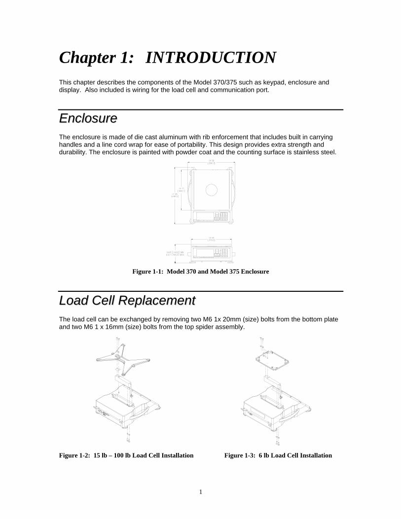
EEnncclloossuurree The enclosure is made of die cast aluminum with rib enforcement that includes built in carrying handles and a line cord wrap for ease of portability. This design provides extra strength and durability. The enclosure is painted with powder coat and the counting surface is stainless steel.
Figure 1-1: Model 370 and Model 375 Enclosure
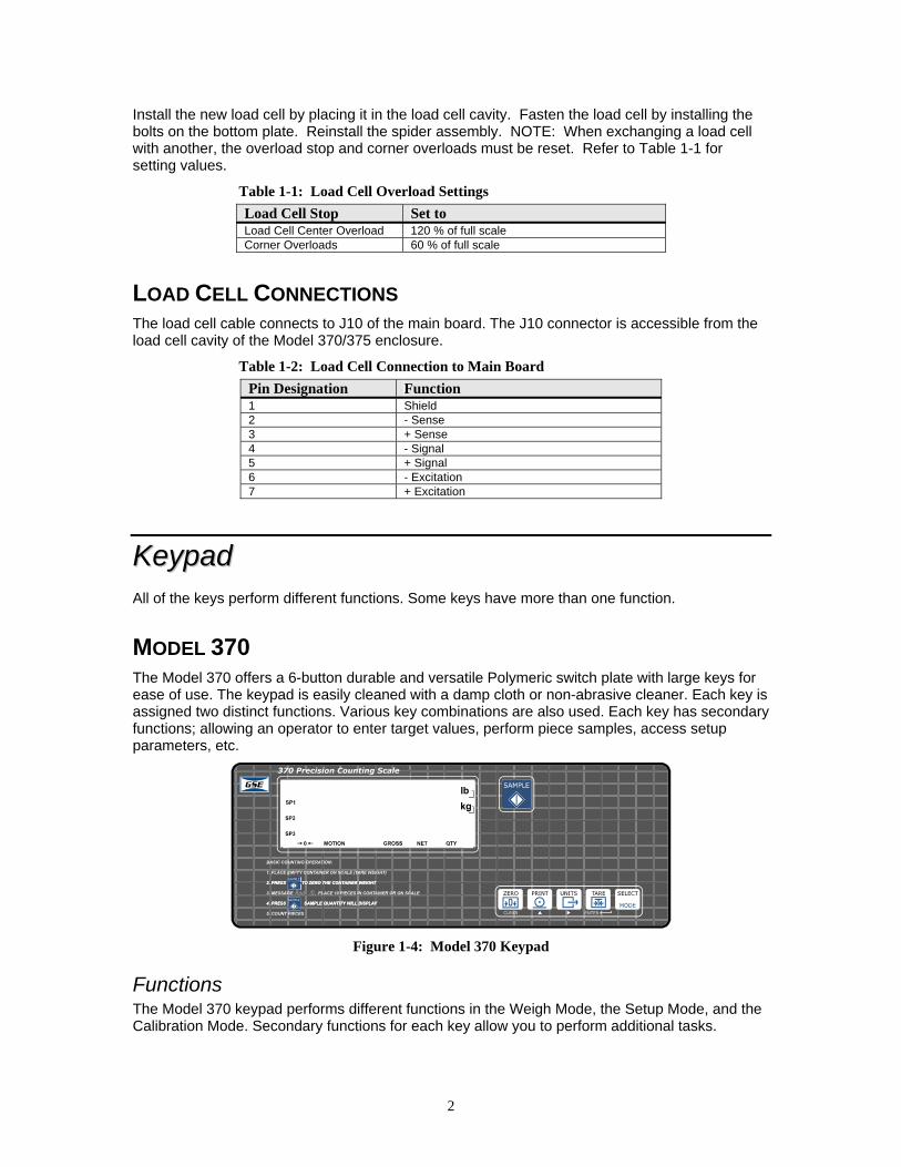
LLooaadd CCeellll RReeppllaacceemmeenntt The load cell can be exchanged by removing two M6 1x 20mm (size) bolts from the bottom plate and two M6 1 x 16mm (size) bolts from the top spider assembly.
Figure 1-2: 15 lb – 100 lb Load Cell Installation Figure 1-3: 6 lb Load Cell Installation
2
Install the new load cell by placing it in the load cell cavity. Fasten the load cell by installing the bolts on the bottom plate. Reinstall the spider assembly. NOTE: When exchanging a load cell with another, the overload stop and corner overloads must be reset. Refer to Table 1-1 for setting values.
Table 1-1: Load Cell Overload Settings Load Cell Stop Set to Load Cell Center Overload 120 % of full scale Corner Overloads 60 % of full scale
LOAD CELL CONNECTIONS The load cell cable connects to J10 of the main board. The J10 connector is accessible from the load cell cavity of the Model 370/375 enclosure.
Table 1-2: Load Cell Connection to Main Board Pin Designation Function 1 Shield 2 - Sense 3 + Sense 4 - Signal 5 + Signal 6 - Excitation 7 + Excitation
KKeeyyppaadd All of the keys perform different functions. Some keys have more than one function.
MODEL 370 The Model 370 offers a 6-button durable and versatile Polymeric switch plate with large keys for ease of use. The keypad is easily cleaned with a damp cloth or non-abrasive cleaner. Each key is assigned two distinct functions. Various key combinations are also used. Each key has secondary functions; allowing an operator to enter target values, perform piece samples, access setup parameters, etc.
Figure 1-4: Model 370 Keypad
Functions The Model 370 keypad performs different functions in the Weigh Mode, the Setup Mode, and the Calibration Mode. Secondary functions for each key allow you to perform additional tasks.

3
Key Press Weigh Mode Count Mode Setup Mode
Performs a gross zero function and/or clears an entry in progress. Hold this key on power-up to turn on the display regardless of P420.
Performs a quantity zero function and/or clears an entry in progress.
Exits the Setup Mode and/or answers “NO” to query prompts and/or clears an entry in progress.
Performs a print function and/or ‘scrolls’ through digits during setpoint entry.
Performs a print function and/or ‘scrolls’ through digits during setpoint entry.
‘Scrolls’ through digits during data entry.
Toggles between ‘lb’, ‘kg’ third unit (if enabled) and/or advances cursor to next entry position.
Toggles through standard sample sizes during a sample and/or begins a new sample entry.
Advances cursor to next entry position and/or cycles prompts.
Performs an auto-tare function (if enabled) and/or accepts an entry in progress.
Performs an auto-tare function and/or accepts an entry in progress.
Accepts an entry in progress and/or ‘scrolls’ through parameter sub-set selections and/or answers ‘YES’ to query prompts.
Toggles between display modes and/or restores power to the Model 370/375 (if auto-shutoff enabled).
Toggles between display modes and/or restores power to the Model 370/375 (if auto-shutoff enabled) and/or toggles through standard sample sizes during a sample.
Advances to the next setup parameter.
Goes to the count mode
Performs a sample for an accurate part count and calculates an average piece weight.
Accepts an entry in progress and/or ‘scrolls’ through parameter sub-set selections and/or answers ‘YES’ to query prompts.
Access Setup Mode. Break out of remote display mode.
Access Setup Mode. Break out of remote display mode.
No function.
No function. No function. Return to the previous setup parameter.
Absolute clear – clears an entry in progress and/or clears the value of a parameter.
No function. Clears any entry in progress.
Backspace – erases the right-most digit during data entry.
Backspace – erases the right-most digit during sample entry.
Backspace – erases right-most digit during data entry.
Extended gross. Extended gross. Shows parameter number.
Reverse character scroll during data entry.
Reverse character scroll during sample entry.
Reverse character scroll during data entry.
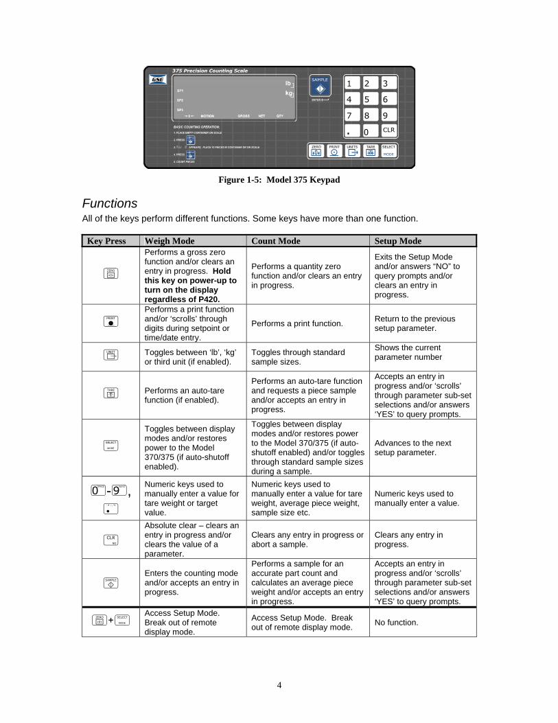
MODEL 375 The Model 375 offers an 18-button durable and versatile Polymeric switch plate with large keys for ease of use. The keypad is easily cleaned with a damp cloth or non-abrasive cleaner. The number keys make entering a tare value or average piece weight easier. Each key is assigned at least one distinct function.
4
Figure 1-5: Model 375 Keypad
Functions All of the keys perform different functions. Some keys have more than one function.
Key Press Weigh Mode Count Mode Setup Mode
Performs a gross zero function and/or clears an entry in progress. Hold this key on power-up to turn on the display regardless of P420.
Performs a quantity zero function and/or clears an entry in progress.
Exits the Setup Mode and/or answers “NO” to query prompts and/or clears an entry in progress.
Performs a print function and/or ‘scrolls’ through digits during setpoint or time/date entry.
Performs a print function. Return to the previous setup parameter.
Toggles between ‘lb’, ‘kg’ or third unit (if enabled).
Toggles through standard sample sizes.
Shows the current parameter number
Performs an auto-tare function (if enabled).
Performs an auto-tare function and requests a piece sample and/or accepts an entry in progress.
Accepts an entry in progress and/or ‘scrolls’ through parameter sub-set selections and/or answers ‘YES’ to query prompts.
Toggles between display modes and/or restores power to the Model 370/375 (if auto-shutoff enabled).
Toggles between display modes and/or restores power to the Model 370/375 (if auto-shutoff enabled) and/or toggles through standard sample sizes during a sample.
Advances to the next setup parameter.
- ,
Numeric keys used to manually enter a value for tare weight or target value.
Numeric keys used to manually enter a value for tare weight, average piece weight, sample size etc.
Numeric keys used to manually enter a value.
Absolute clear – clears an entry in progress and/or clears the value of a parameter.
Clears any entry in progress or abort a sample.
Clears any entry in progress.
Enters the counting mode and/or accepts an entry in progress.
Performs a sample for an accurate part count and calculates an average piece weight and/or accepts an entry in progress.
Accepts an entry in progress and/or ‘scrolls’ through parameter sub-set selections and/or answers ‘YES’ to query prompts.
Access Setup Mode. Break out of remote display mode.
Access Setup Mode. Break out of remote display mode. No function.
5
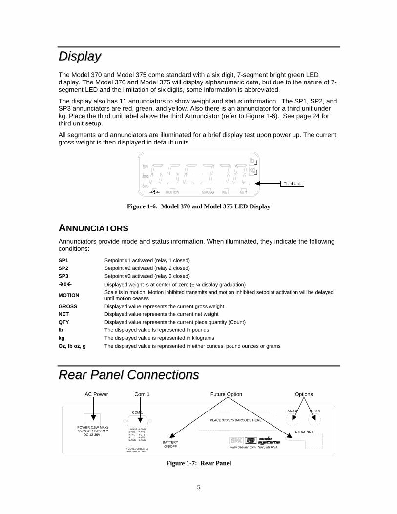
DDiissppllaayy The Model 370 and Model 375 come standard with a six digit, 7-segment bright green LED display. The Model 370 and Model 375 will display alphanumeric data, but due to the nature of 7-segment LED and the limitation of six digits, some information is abbreviated.
The display also has 11 annunciators to show weight and status information. The SP1, SP2, and SP3 annunciators are red, green, and yellow. Also there is an annunciator for a third unit under kg. Place the third unit label above the third Annunciator (refer to Figure 1-6). See page 24 for third unit setup.
All segments and annunciators are illuminated for a brief display test upon power up. The current gross weight is then displayed in default units.
Figure 1-6: Model 370 and Model 375 LED Display
ANNUNCIATORS Annunciators provide mode and status information. When illuminated, they indicate the following conditions:
SP1 Setpoint #1 activated (relay 1 closed) SP2 Setpoint #2 activated (relay 2 closed) SP3 Setpoint #3 activated (relay 3 closed)
0 Displayed weight is at center-of-zero (± ¼ display graduation)
MOTION Scale is in motion. Motion inhibited transmits and motion inhibited setpoint activation will be delayed until motion ceases
GROSS Displayed value represents the current gross weight NET Displayed value represents the current net weight QTY Displayed value represents the current piece quantity (Count) lb The displayed value is represented in pounds kg The displayed value is represented in kilograms Oz, lb oz, g The displayed value is represented in either ounces, pound ounces or grams
RReeaarr PPaanneell CCoonnnneeccttiioonnss
ETHERNET
AUX 3AUX 2COM 1
BATTERYON/OFF www.gse-inc.com Novi, MI USA
PLACE 370/375 BARCODE HERE
POWER (15W MAX)50-60 Hz 12-20 VAC
DC 12-36V
1 NONE2 RXD3 TXD4 *5 GND
6 GND7 RTS8 CTS9 +5V5 GND
MOVE JUMBER E6FOR +5V ON PIN 4
Figure 1-7: Rear Panel
AC Power Com 1 Options Future Option
Third Unit
6
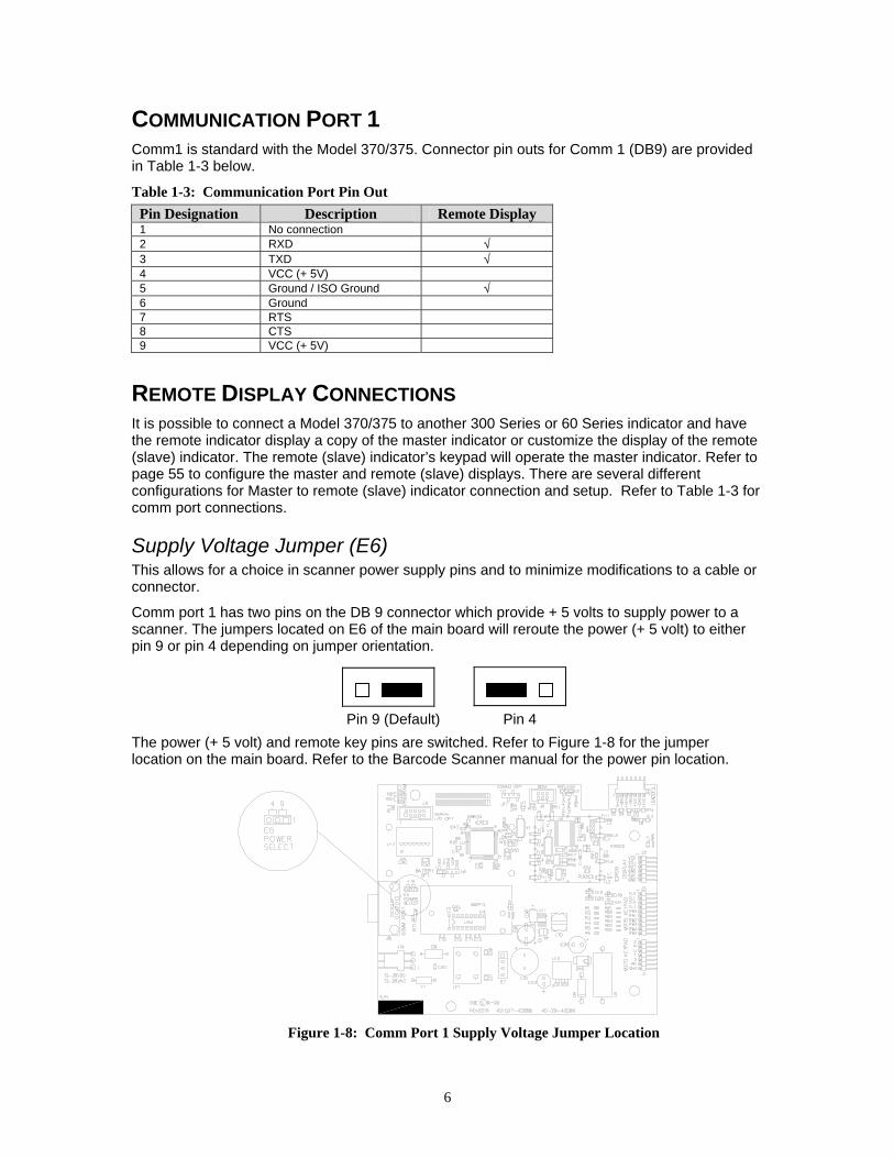
COMMUNICATION PORT 1 Comm1 is standard with the Model 370/375. Connector pin outs for Comm 1 (DB9) are provided in Table 1-3 below.
Table 1-3: Communication Port Pin Out Pin Designation Description Remote Display 1 No connection 2 RXD √ 3 TXD √ 4 VCC (+ 5V) 5 Ground / ISO Ground √ 6 Ground 7 RTS 8 CTS 9 VCC (+ 5V)
REMOTE DISPLAY CONNECTIONS It is possible to connect a Model 370/375 to another 300 Series or 60 Series indicator and have the remote indicator display a copy of the master indicator or customize the display of the remote (slave) indicator. The remote (slave) indicator’s keypad will operate the master indicator. Refer to page 55 to configure the master and remote (slave) displays. There are several different configurations for Master to remote (slave) indicator connection and setup. Refer to Table 1-3 for comm port connections.
Supply Voltage Jumper (E6) This allows for a choice in scanner power supply pins and to minimize modifications to a cable or connector.
Comm port 1 has two pins on the DB 9 connector which provide + 5 volts to supply power to a scanner. The jumpers located on E6 of the main board will reroute the power (+ 5 volt) to either pin 9 or pin 4 depending on jumper orientation.
The power (+ 5 volt) and remote key pins are switched. Refer to Figure 1-8 for the jumper location on the main board. Refer to the Barcode Scanner manual for the power pin location.
Figure 1-8: Comm Port 1 Supply Voltage Jumper Location
Pin 9 (Default) Pin 4

7
Chapter 2: OPTION INSTALLATION This chapter will provide detailed instructions on installing each option. Additional hardware may be needed for the Model 370/375 depending on which options you will be installing.
Also this chapter provides instructions on how to configure all Model 370 / 375 options. This includes setup mode parameters, connections, calibration and testing.
CCoommmmuunniiccaattiioonn
RS-485 NETWORKING The module converts the standard RS-232 communication on comm port 1 to RS-485. However the advantage of using the RS-485 module, aside from the ability to transmit over long distances, is the ability to network multiple indicators or parts counters using the same communication wires. When networking indicators or parts counter, it is necessary to set up a network address for each scale. The network module itself does not require addressing, rather each indicator or parts counter must be enabled for network addressing in the setup mode. Refer to page 26 for details on the RS-485 enable parameter (P250) and the network address parameter (P251).
Installation Instructions 1. DISCONNECT POWER! UNPLUG THE MODEL 370/375 TO INSURE DAMAGE WILL NOT
OCCUR DURING OPTION INSTALLATION. 2. Remove the six 8 mm screws (size) from the bottom plate. Separate the top enclosure from
the bottom plate. 3. Remove the IC chip and white jumper from the U4 socket on the main board. 4. Snap in the plastic spacers into the three mounting holes surrounding the U4 socket. Refer
to Figure 2-1. 5. Gently press the option board into the socket and make sure the board snaps onto the
standoffs. 6. Reinstall the enclosure bottom plate.
Figure 2-1: RS-485 / 20 mA Option Installation
RS-485 Connections (Comm Port 1) The Model 370/375 will be connected to a peripheral via the DB 9 connector on comm port 1. Refer to Table 2-1 for wiring connections.
8
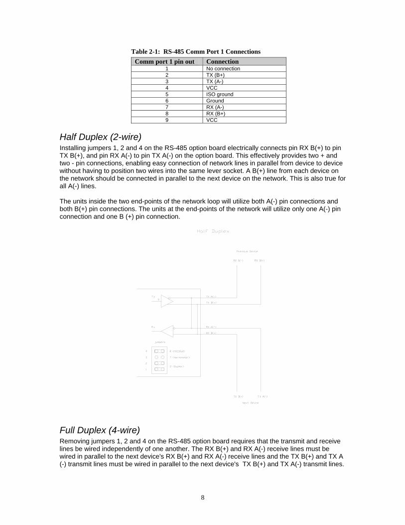
Table 2-1: RS-485 Comm Port 1 Connections Comm port 1 pin out Connection
1 No connection 2 TX (B+) 3 TX (A-) 4 VCC 5 ISO ground 6 Ground 7 RX (A-) 8 RX (B+) 9 VCC
Half Duplex (2-wire) Installing jumpers 1, 2 and 4 on the RS-485 option board electrically connects pin RX B(+) to pin TX B(+), and pin RX A(-) to pin TX A(-) on the option board. This effectively provides two + and two - pin connections, enabling easy connection of network lines in parallel from device to device without having to position two wires into the same lever socket. A B(+) line from each device on the network should be connected in parallel to the next device on the network. This is also true for all A(-) lines. The units inside the two end-points of the network loop will utilize both A(-) pin connections and both B(+) pin connections. The units at the end-points of the network will utilize only one A(-) pin connection and one B (+) pin connection.
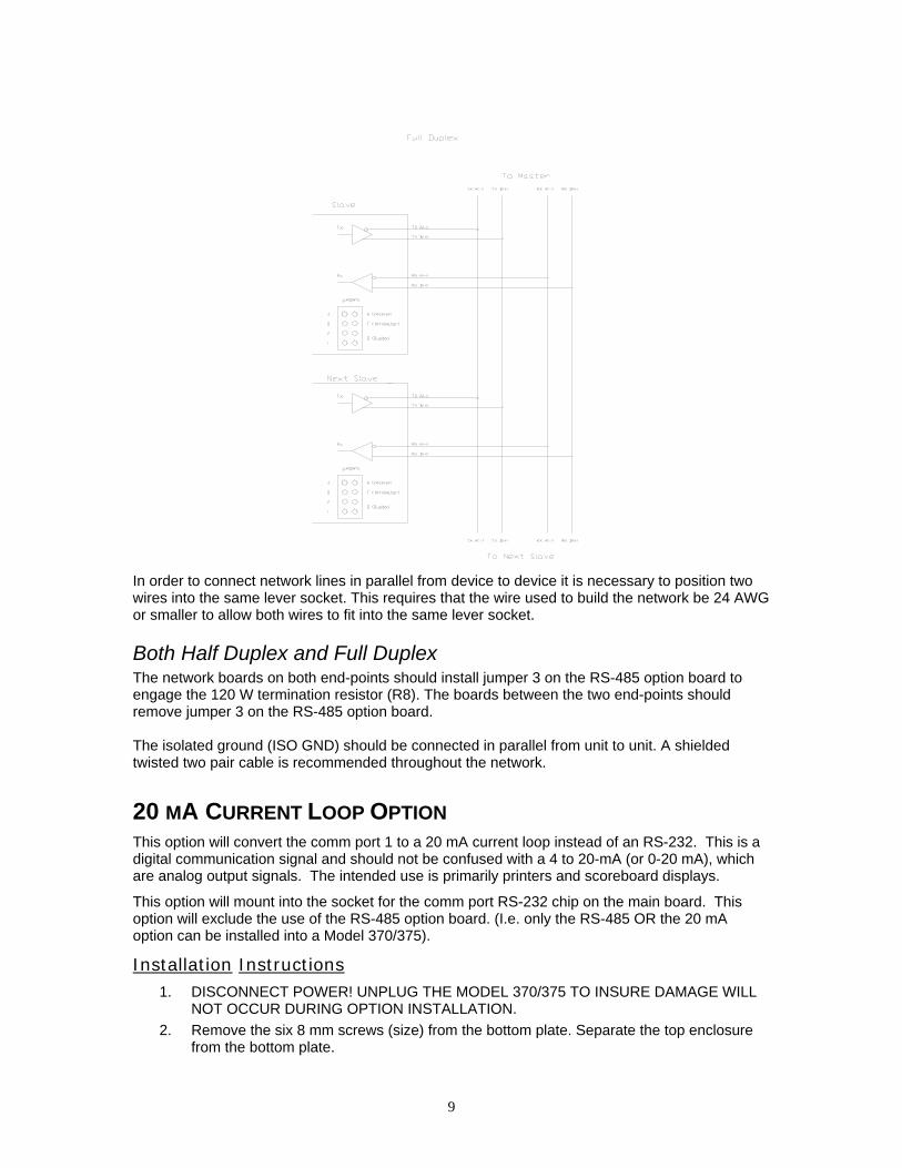
Full Duplex (4-wire) Removing jumpers 1, 2 and 4 on the RS-485 option board requires that the transmit and receive lines be wired independently of one another. The RX B(+) and RX A(-) receive lines must be wired in parallel to the next device's RX B(+) and RX A(-) receive lines and the TX B(+) and TX A (-) transmit lines must be wired in parallel to the next device's TX B(+) and TX A(-) transmit lines.
9
In order to connect network lines in parallel from device to device it is necessary to position two wires into the same lever socket. This requires that the wire used to build the network be 24 AWG or smaller to allow both wires to fit into the same lever socket.
Both Half Duplex and Full Duplex The network boards on both end-points should install jumper 3 on the RS-485 option board to engage the 120 W termination resistor (R8). The boards between the two end-points should remove jumper 3 on the RS-485 option board. The isolated ground (ISO GND) should be connected in parallel from unit to unit. A shielded twisted two pair cable is recommended throughout the network.
20 MA CURRENT LOOP OPTION
This option will convert the comm port 1 to a 20 mA current loop instead of an RS-232. This is a digital communication signal and should not be confused with a 4 to 20-mA (or 0-20 mA), which are analog output signals. The intended use is primarily printers and scoreboard displays.
This option will mount into the socket for the comm port RS-232 chip on the main board. This option will exclude the use of the RS-485 option board. (I.e. only the RS-485 OR the 20 mA option can be installed into a Model 370/375).
Installation Instructions 1. DISCONNECT POWER! UNPLUG THE MODEL 370/375 TO INSURE DAMAGE WILL
NOT OCCUR DURING OPTION INSTALLATION. 2. Remove the six 8 mm screws (size) from the bottom plate. Separate the top enclosure
from the bottom plate.
10
3. Remove U4 and the white jumper from the socket of the main board. 4. Snap in the plastic spacers into the three mounting holes surrounding the U4 socket.
Refer to Figure 2-1. 5. Gently press the option board into the socket and make sure the board snaps onto the
standoffs. 6. Reinstall the enclosure bottom plate.
BI-Directional Both the transmit output and the receive input of the Model 370/375 are available as 20 mA signals. None of the handshake signals are supported for the 20-mA current loop operation.
Baud Only baud rates of 9600 baud and less are supported.
Active/Passive The Tx output may be used as an active or passive output from the Model 370/375. Either active or passive is chosen depending upon which terminals are used for the connections. In active mode the Model 370/375 supplies the current. In passive mode, the external device supplies the current. The Rx input is available in passive mode only.
Isolation The input and output are electrically isolated from the main board as well as earth ground and each other, for both passive and active modes of operation. Isolation is a minimum of 1000v.
Max Voltage Active mode Tx current loop provides a driving voltage of 12v. This will allow 20 mA current flow with up to a 600 ohm load. Passive mode will work with an external driving voltage of up to 50v.
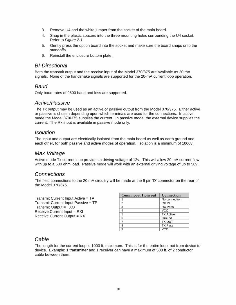
Connections The field connections to the 20 mA circuitry will be made at the 9 pin 'D' connector on the rear of the Model 370/375. Transmit Current Input Active = TA Transmit Current Input Passive = TP Transmit Output = TXO Receive Current Input = RXI Receive Current Output = RX
Cable The length for the current loop is 1000 ft. maximum. This is for the entire loop, not from device to device. Example: 1 transmitter and 1 receiver can have a maximum of 500 ft. of 2 conductor cable between them.
Comm port 1 pin out Connection 1 No connection 2 RX IN 3 RX Pass 4 VCC 5 TX Active 6 Ground 7 TX OUT 8 TX Pass 9 VCC

11
Connected Devices While 20 mA current loops can allow for more than one transmitter and/or receiver, the Model 370/375 and/or option board do not include any address recognition or collision avoidance and/or detection to promote this usage. If the 20-mA loop is intended to be used in this manner, proper planning for these issues is required.
Table 2-2: Connecting to External Devices Typical Installations
Model 370/375 External Device TP RX+ Passive 20 mA Output TXO RX- Active 20 mA Input
RXI RX+ Passive 20 mA Input RX RX- Active 20 mA Output
TXO RX+ Active 20 mA Output TA RX- Passive 20 mA Input
AAnnaalloogg OOuuttppuutt OOppttiioonn This section provides procedures for installing and configuring the analog output module.
The analog output modules enable the Model 370/375 to generate a 0-10VDC, active 0-20mA or active 4-20mA output signal corresponding to the value of most operating parameters. For parameter setup see page 35. For details on testing and troubleshooting see page 77. For analog output calibration see page 71. Requires an option mounting bracket kit (24370B-300A0) for internal installation.
Installation Instructions 1. DISCONNECT POWER! UNPLUG THE MODEL 370/375 TO INSURE DAMAGE WILL NOT
OCCUR DURING OPTION INSTALLATION 2. Remove the (6) 38-31-8710 M5 x 0.8 x 10 mm screws from the enclosure bottom plate and
set it aside. 3. Discard the mounting hardware provided with the analog output kit and use the hardware
provided with the option-mounting bracket kit. Refer to page 13 for parts included with this kit.
4. Snap in the (4) nylon spacers in the 4 holes either to the right of the notch or the left of the notch in the option mounting bracket.
5. Position the Analog Output Option Board on the spacers so the ribbon cable points away from the notch on the option-mounting bracket. Carefully press the analog output option onto the spacers.
6. Install the (4) nylon hex nuts to secure the option board. Refer to Figure 2-3 for details. 7. If a setpoint option is also being used, connect the 6" option ribbon cable from J1 of the
analog output option board to J1 of the setpoint option board. 8. Connect the 22-30-25520 6.5" ribbon cable (optional) to from J2 of the analog output board to
J3 of the main board. 9. Install the option-mounting bracket in the Model 370/375 enclosure. Refer to page 13 for
option mounting bracket installation instructions. 10. Connect all necessary wiring to the Analog Output Option Board. 11. Reinstall the enclosure bottom plate.
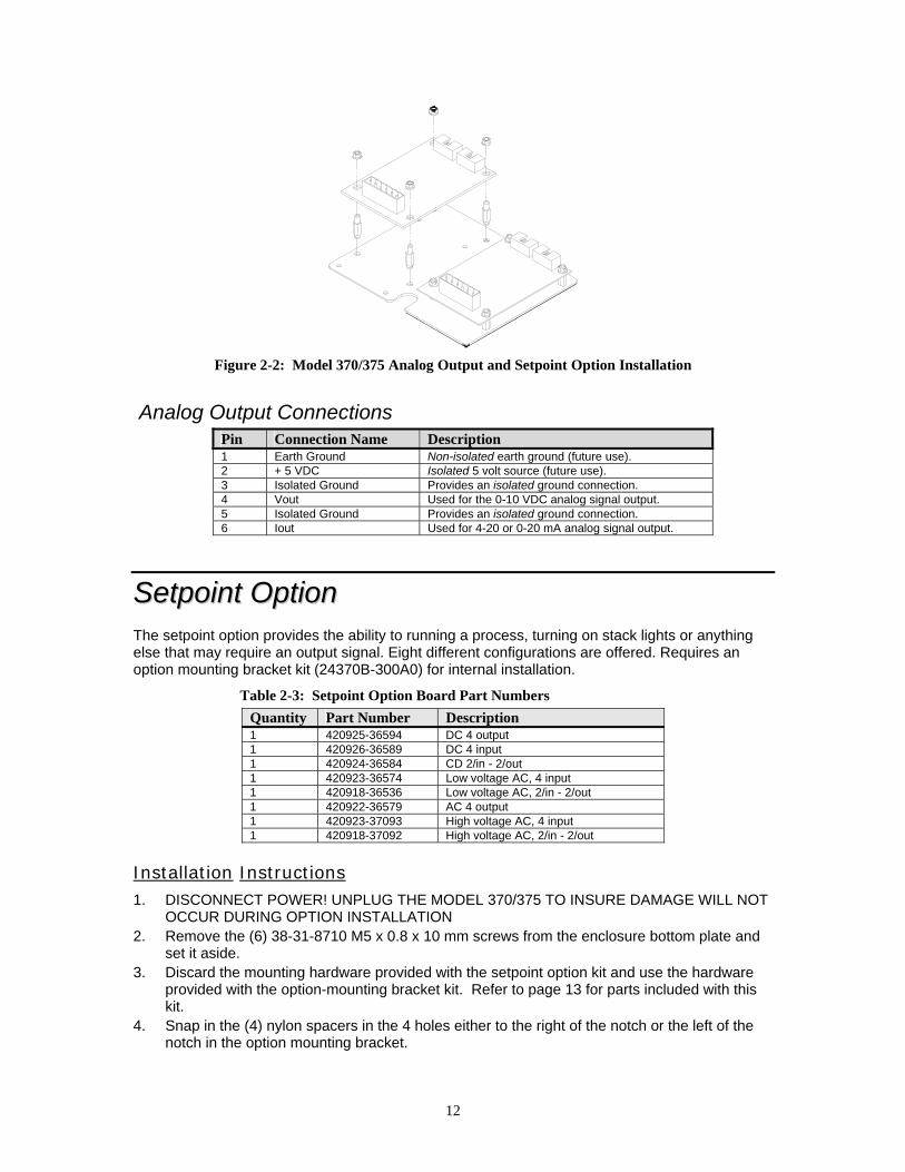
12
Figure 2-2: Model 370/375 Analog Output and Setpoint Option Installation
Analog Output Connections
Pin Connection Name Description 1 Earth Ground Non-isolated earth ground (future use). 2 + 5 VDC Isolated 5 volt source (future use). 3 Isolated Ground Provides an isolated ground connection. 4 Vout Used for the 0-10 VDC analog signal output. 5 Isolated Ground Provides an isolated ground connection. 6 Iout Used for 4-20 or 0-20 mA analog signal output.
SSeettppooiinntt OOppttiioonn The setpoint option provides the ability to running a process, turning on stack lights or anything else that may require an output signal. Eight different configurations are offered. Requires an option mounting bracket kit (24370B-300A0) for internal installation.
Table 2-3: Setpoint Option Board Part Numbers Quantity Part Number Description 1 420925-36594 DC 4 output 1 420926-36589 DC 4 input 1 420924-36584 CD 2/in - 2/out 1 420923-36574 Low voltage AC, 4 input 1 420918-36536 Low voltage AC, 2/in - 2/out 1 420922-36579 AC 4 output 1 420923-37093 High voltage AC, 4 input 1 420918-37092 High voltage AC, 2/in - 2/out
Installation Instructions 1. DISCONNECT POWER! UNPLUG THE MODEL 370/375 TO INSURE DAMAGE WILL NOT
OCCUR DURING OPTION INSTALLATION 2. Remove the (6) 38-31-8710 M5 x 0.8 x 10 mm screws from the enclosure bottom plate and
set it aside. 3. Discard the mounting hardware provided with the setpoint option kit and use the hardware
provided with the option-mounting bracket kit. Refer to page 13 for parts included with this kit.
4. Snap in the (4) nylon spacers in the 4 holes either to the right of the notch or the left of the notch in the option mounting bracket.
13
5. Position the setpoint option board on the spacers so the ribbon cable points away from the notch on the option-mounting bracket. Carefully press the analog output option onto the spacers.
6. Install the (4) nylon hex nuts to secure the option board. Refer to Figure 2-3 for details. 7. If an analog output option is also being used, connect the 6" option ribbon cable from J1 of
the setpoint option board to J1 of the analog output option board. 8. Connect the 22-30-25520 6.5" ribbon cable (optional) to from J2 of the setpoint board to J3
of the main board. 9. Install the option-mounting bracket in the Model 370/375 enclosure. Refer to page 13 for
option mounting bracket installation instructions. 10. Connect all necessary wiring to the setpoint option board. 11. Reinstall the enclosure bottom plate.
SETPOINT CARD CONNECTIONS Using one of the software setpoint configurations (see General Setpoint Setup on page 36) in conjunction with the setpoint option board gives the Model 370/375 the ability to directly control external devices such as valves, relays, actuators, etc.
There are up to three setpoint outputs available. The activation and deactivation is controlled by the setpoint configuration. The outputs are capable of driving up to one Amp at 20-280VAC & 2 Amp at 3-60VDC. The solid state relays are normally open (NO) contacts.
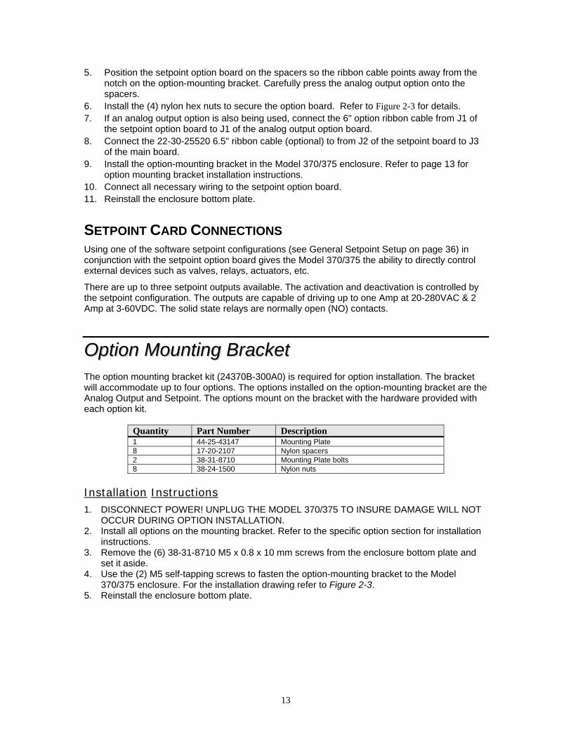
OOppttiioonn MMoouunnttiinngg BBrraacckkeett The option mounting bracket kit (24370B-300A0) is required for option installation. The bracket will accommodate up to four options. The options installed on the option-mounting bracket are the Analog Output and Setpoint. The options mount on the bracket with the hardware provided with each option kit.
Quantity Part Number Description 1 44-25-43147 Mounting Plate 8 17-20-2107 Nylon spacers 2 38-31-8710 Mounting Plate bolts 8 38-24-1500 Nylon nuts
Installation Instructions 1. DISCONNECT POWER! UNPLUG THE MODEL 370/375 TO INSURE DAMAGE WILL NOT
OCCUR DURING OPTION INSTALLATION. 2. Install all options on the mounting bracket. Refer to the specific option section for installation
instructions. 3. Remove the (6) 38-31-8710 M5 x 0.8 x 10 mm screws from the enclosure bottom plate and
set it aside. 4. Use the (2) M5 self-tapping screws to fasten the option-mounting bracket to the Model
370/375 enclosure. For the installation drawing refer to Figure 2-3. 5. Reinstall the enclosure bottom plate.

14
Figure 2-3: Option Bracket Installation
15
Chapter 3: SCALE CONFIGURATION This chapter will cover the configuration of the scale parameters and how to configure options such as analog output, setpoint and communication modules.
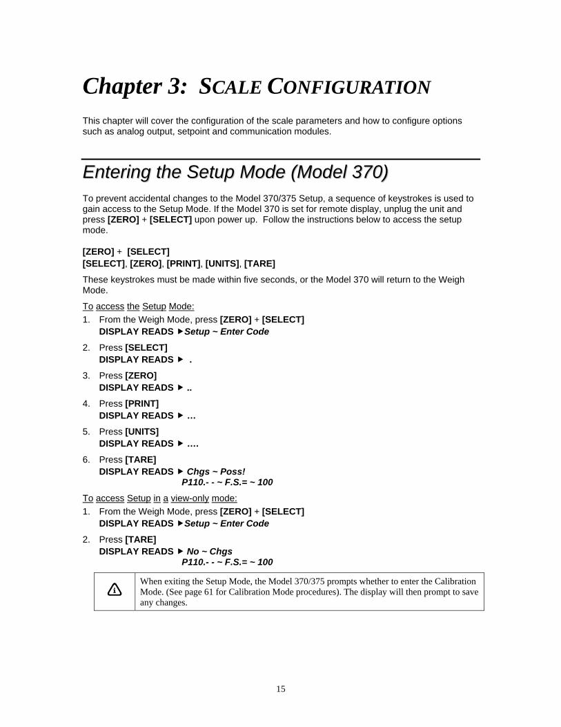
EEnntteerriinngg tthhee SSeettuupp MMooddee ((MMooddeell 337700)) To prevent accidental changes to the Model 370/375 Setup, a sequence of keystrokes is used to gain access to the Setup Mode. If the Model 370 is set for remote display, unplug the unit and press [ZERO] + [SELECT] upon power up. Follow the instructions below to access the setup mode.
[ZERO] + [SELECT] [SELECT], [ZERO], [PRINT], [UNITS], [TARE]
These keystrokes must be made within five seconds, or the Model 370 will return to the Weigh Mode.
To access the Setup Mode: 1. From the Weigh Mode, press [ZERO] + [SELECT]
DISPLAY READS Setup ~ Enter Code
2. Press [SELECT] DISPLAY READS .
3. Press [ZERO] DISPLAY READS ..
4. Press [PRINT] DISPLAY READS …
5. Press [UNITS] DISPLAY READS ….
6. Press [TARE] DISPLAY READS Chgs ~ Poss!
P110.- - ~ F.S.= ~ 100
To access Setup in a view-only mode: 1. From the Weigh Mode, press [ZERO] + [SELECT]
DISPLAY READS Setup ~ Enter Code
2. Press [TARE] DISPLAY READS No ~ Chgs
P110.- - ~ F.S.= ~ 100
When exiting the Setup Mode, the Model 370/375 prompts whether to enter the Calibration Mode. (See page 61 for Calibration Mode procedures). The display will then prompt to save any changes.

16
EEnntteerriinngg tthhee SSeettuupp MMooddee ((MMooddeell 337755)) To prevent accidental changes to the Model 370/375 Setup, a sequence of keystrokes is used to gain access to the Setup Mode. If the Model 375 is set for remote display, unplug the unit and press [ZERO] + [SELECT] upon power up. Follow the instructions below to access the setup mode.
100 [SELECT] 23640 [SAMPLE/Enter]
These keystrokes must be made within five seconds, or the Model 375 will return to the Weigh Mode.
To access the Setup Mode: 1. From the Weigh Mode, key in 100 [SELECT]
DISPLAY READS Setup ~ Enter Code 2. Key in 23640 [SAMPLE/Enter]
DISPLAY READS Chgs ~ Poss! P110.- - ~ F.S.= ~ 100
To access Setup in a view-only mode: 1. From the Weigh Mode, key in 100 [SELECT]
DISPLAY READS Setup ~ Enter Code 2. Press [SAMPLE/Enter]
DISPLAY READS No ~ Chgs P110.- - ~ F.S.= ~ 100
SSeelleeccttiinngg aa PPaarraammeetteerr To advance to the next parameter (Model 370 and Model 375): 1. Press [SELECT]
DISPLAY READS P111.09 ~ 1Grad ~ 0.01 2. Press [SELECT]
DISPLAY READS P112.05 ~ Ztrac ~ 0.5 d 3. Continue pressing [SELECT] to advance through all setup parameters.
To access the previous parameter (Model 370): 1. Press [PRINT]
DISPLAY READS . 2. Press [SELECT]
DISPLAY READS P111.09 ~ 1Grad ~ 0.01 3. Repeat [PRINT] + [SELECT] to back up one parameter.
To access the previous parameter (Model 375): 1. Press [.]
DISPLAY READS . 2. Press [SELECT]
DISPLAY READS P111.09 ~ 1Grad ~ 0.01 3. Repeat [.][SELECT] to back up one parameter.

17
When accessing a parameter, the parameter number appears briefly. The display then toggles between the parameter name and selection. Pressing [UNITS] will again briefly display the parameter number.
To access a specific parameter (for example P200) (Model 370): 1. Press [PRINT] four times to select the first digit.
DISPLAY READS 2
2. Press [UNITS] to advance to the next digit. DISPLAY READS 2.
3. Press [PRINT] once to select the next digit. DISPLAY READS 20
4. Press [UNITS] to advance to the next digit. DISPLAY READS 20.
5. Press [PRINT] once to select the next digit. DISPLAY READS 200
6. Press [SELECT] to advance to the parameter. DISPLAY READS P200.00 ~ Baud ~ 9600
To access a specific parameter (for example P200) (Model 375): 1. Key in 200 [SELECT]
DISPLAY READS P200.00 ~ Baud ~ 9600
CChhaannggiinngg aa PPaarraammeetteerr VVaalluuee
SELECTION PARAMETERS Selection parameters have a pre-defined list of choices to pick from. Each choice is numbered and corresponds to a certain value. The choice number is shown to the right of the decimal point within the parameter number. Repeatedly pressing [TARE] (Model 370) or [SAMPLE/Enter] (Model 375) while viewing a selection parameter cycles through the available choices, or you can key in the choice number.
P 200.00
Indicates Parameter Parameter Number Choice Number
For example, parameter 200 (P200) is a selection parameter that holds the baud rate for the serial port. This is a selection parameter because a choice number between 00 and 12 must be used. Each choice number corresponds to a different baud rate. To change the baud rate from the default value of 9600 to 4800, perform the following steps from the Setup Mode.
To change the baud rate from the default value of 9600 to 4800: 1. Key in 200 [SELECT]
DISPLAY READS P200.00 ~ Baud ~ 9600
2. Press [TARE] (Model 370) or [SAMPLE/Enter] (Model 375) once. DISPLAY READS P200.01 ~ Baud ~ 4800
18
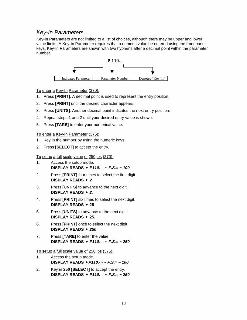
Key-In Parameters Key-In Parameters are not limited to a list of choices, although there may be upper and lower value limits. A Key-In Parameter requires that a numeric value be entered using the front panel keys. Key-In Parameters are shown with two hyphens after a decimal point within the parameter number.
P 110.--
Indicates Parameter Parameter Number Denotes “Key In”
To enter a Key-In Parameter (370): 1. Press [PRINT]. A decimal point is used to represent the entry position.
2. Press [PRINT] until the desired character appears.
3. Press [UNITS]. Another decimal point indicates the next entry position.
4. Repeat steps 1 and 2 until your desired entry value is shown.
5. Press [TARE] to enter your numerical value.
To enter a Key-In Parameter (375): 1. Key in the number by using the numeric keys.
2. Press [SELECT] to accept the entry.
To setup a full scale value of 250 lbs (370): 1. Access the setup mode. DISPLAY READS P110.- - ~ F.S.= ~ 100
2. Press [PRINT] four times to select the first digit. DISPLAY READS 2
3. Press [UNITS] to advance to the next digit. DISPLAY READS 2.
4. Press [PRINT] six times to select the next digit. DISPLAY READS 25
5. Press [UNITS] to advance to the next digit. DISPLAY READS 25.
6. Press [PRINT] once to select the next digit. DISPLAY READS 250
7. Press [TARE] to enter the value. DISPLAY READS P110.- - ~ F.S.= ~ 250
To setup a full scale value of 250 lbs (375): 1. Access the setup mode. DISPLAY READS P110.- - ~ F.S.= ~ 100
2. Key in 250 [SELECT] to accept the entry. DISPLAY READS P110.- - ~ F.S.= ~ 250

19
SSaavviinngg PPaarraammeetteerrss To exit the Setup Mode and save changes (370): 1. Press [ZERO] to begin exiting Setup Mode.
DISPLAY READS Enter ~ =CAL!
2. Press [ZERO] to bypass Calibration Mode. DISPLAY READS Enter ~ =Stor
3. Press [TARE] to save setup changes. DISPLAY READS Enter ~ =End
4. Press [TARE] to complete exit. DISPLAY READS 0.00
To exit the Setup Mode and save changes (375): 1. Press [ZERO] to begin exiting Setup Mode.
DISPLAY READS Enter ~ =CAL!
2. Press [CLR] to bypass Calibration Mode. DISPLAY READS Enter ~ =Stor
3. Press [SAMPLE/Enter] to save setup changes. DISPLAY READS Enter ~ =End
4. Press [SAMPLE/Enter] to complete exit. DISPLAY READS 0.00
To exit the Setup Mode from the view-only mode (370 and 375): 1. Press [ZERO] to begin exiting Setup Mode.
DISPLAY READS Enter ~ =End
2. Press [TARE] (370) or [SAMPLE/Enter] (375) to complete exit. DISPLAY READS 0.00
To exit the Setup Mode without saving changes (370): 1. Press [ZERO] to begin exiting Setup Mode.
DISPLAY READS Enter ~ =CAL!
2. Press [ZERO] to bypass Calibration Mode. DISPLAY READS Enter ~ =Stor
3. Press [ZERO] to exit without saving changes. DISPLAY READS Enter ~ =Undo
4. Press [TARE] to undo changes. DISPLAY READS Enter ~ =End
5. Press [TARE] to complete exit. DISPLAY READS 0.00
To exit the Setup Mode without saving changes (375):
1. Press [ZERO] to begin exiting Setup Mode. DISPLAY READS Enter ~ =CAL!
2. Press [CLR] to bypass Calibration Mode. DISPLAY READS Enter ~ =Stor
20
3. Press [CLR] to exit without saving changes. DISPLAY READS Enter ~ =Undo
4. Press [SAMPLE/Enter] to undo changes. DISPLAY READS Enter ~ =End
5. Press [SAMPLE/Enter] to complete exit. DISPLAY READS 0.00
FFaaccttoorryy DDeeffaauulltt Parameter 65001 and 65002 are available to return the Model 370/375 to factory settings. Parameter 65001 will reset parameters including the calibration, while parameter 65002 resets all parameters except the calibration.
After a factory default is performed and saved the Model 370/375 will be in the Quantity mode. The display will show ‘do APS’ which means an average piece weight needs to be established. Either perform a sample (refer to page 50) or press [SELECT] to chose another mode.
Return to factory default (370): 1. Access the setup mode. See page 15. 2. Key in 65001 or 65002 [SELECT]
DISPLAY READS P65002~default-Cal
3. Press [TARE] once. DISPLAY READS Are U sure?~default=Enter
4. Press [TARE] once. DISPLAY READS Setup done~P65002~default-Cal
5. Press [ZERO] [ZERO] [TARE] [TARE] DISPLAY READS do APS
Return to factory default (375): 1. Access the setup mode. See page 15. 2. Key in 65001 or 65002 [SELECT]
DISPLAY READS P65002~default-Cal
3. Press [SAMPLE/Enter] once. DISPLAY READS Are U sure?~default=Enter
4. Press [SAMPLE/Enter] once. DISPLAY READS Setup done~P65002~default-Cal
5. Press [ZERO] [CLR] [SAMPLE/Enter] [SAMPLE/Enter] DISPLAY READS do APS
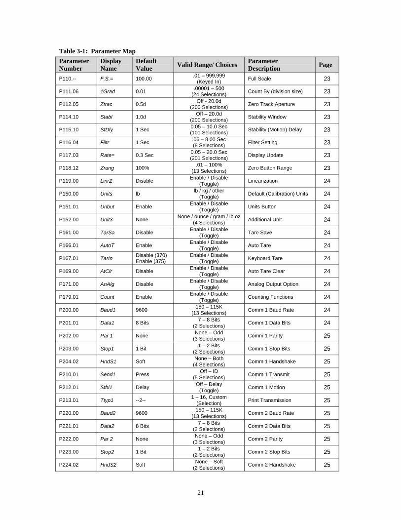
LLiisstt ooff PPaarraammeetteerrss The Model 370 and Model 375 have several parameters that can be configured to your specific application. Table 3-1 is a complete list of the available parameters. Also refer to page 23 for explanations of each parameter. The parameters shaded in gray do not apply to the Model 370/375.
21
Table 3-1: Parameter Map Parameter Number
Display Name
Default Value Valid Range/ Choices Parameter
Description Page
P110.-- F.S.= 100.00 .01 – 999,999 (Keyed In) Full Scale 23
P111.06 1Grad 0.01 .00001 – 500 (24 Selections) Count By (division size) 23
P112.05 Ztrac 0.5d Off - 20.0d (200 Selections) Zero Track Aperture 23
P114.10 Stabl 1.0d Off – 20.0d (200 Selections) Stability Window 23
P115.10 StDly 1 Sec 0.05 – 10.0 Sec (101 Selections) Stability (Motion) Delay 23
P116.04 Filtr 1 Sec .06 – 8.00 Sec (8 Selections) Filter Setting 23
P117.03 Rate= 0.3 Sec 0.05 – 20.0 Sec (201 Selections) Display Update 23
P118.12 Zrang 100% .01 – 100% (13 Selections) Zero Button Range 23
P119.00 LinrZ Disable Enable / Disable (Toggle) Linearization 24
P150.00 Units lb lb / kg / other (Toggle) Default (Calibration) Units 24
P151.01 Unbut Enable Enable / Disable (Toggle) Units Button 24
P152.00 Unit3 None None / ounce / gram / lb oz (4 Selections) Additional Unit 24
P161.00 TarSa Disable Enable / Disable (Toggle) Tare Save 24
P166.01 AutoT Enable Enable / Disable (Toggle) Auto Tare 24
P167.01 TarIn Disable (370) Enable (375)
Enable / Disable (Toggle) Keyboard Tare 24
P169.00 AtClr Disable Enable / Disable (Toggle) Auto Tare Clear 24
P171.00 AnAlg Disable Enable / Disable (Toggle) Analog Output Option 24
P179.01 Count Enable Enable / Disable (Toggle) Counting Functions 24
P200.00 Baud1 9600 150 – 115K (13 Selections) Comm 1 Baud Rate 24
P201.01 Data1 8 Bits 7 – 8 Bits (2 Selections) Comm 1 Data Bits 24
P202.00 Par 1 None None – Odd (3 Selections) Comm 1 Parity 25
P203.00 Stop1 1 Bit 1 – 2 Bits (2 Selections) Comm 1 Stop Bits 25
P204.02 HndS1 Soft None – Both (4 Selections) Comm 1 Handshake 25
P210.01 Send1 Press Off – ID (5 Selections) Comm 1 Transmit 25
P212.01 Stbl1 Delay Off – Delay (Toggle) Comm 1 Motion 25
P213.01 Ttyp1 --2-- 1 – 16, Custom (Selection) Print Transmission 25
P220.00 Baud2 9600 150 – 115K (13 Selections) Comm 2 Baud Rate 25
P221.01 Data2 8 Bits 7 – 8 Bits (2 Selections) Comm 2 Data Bits 25
P222.00 Par 2 None None – Odd (3 Selections) Comm 2 Parity 25
P223.00 Stop2 1 Bit 1 – 2 Bits (2 Selections) Comm 2 Stop Bits 25
P224.02 HndS2 Soft None – Soft (2 Selections) Comm 2 Handshake 25
22
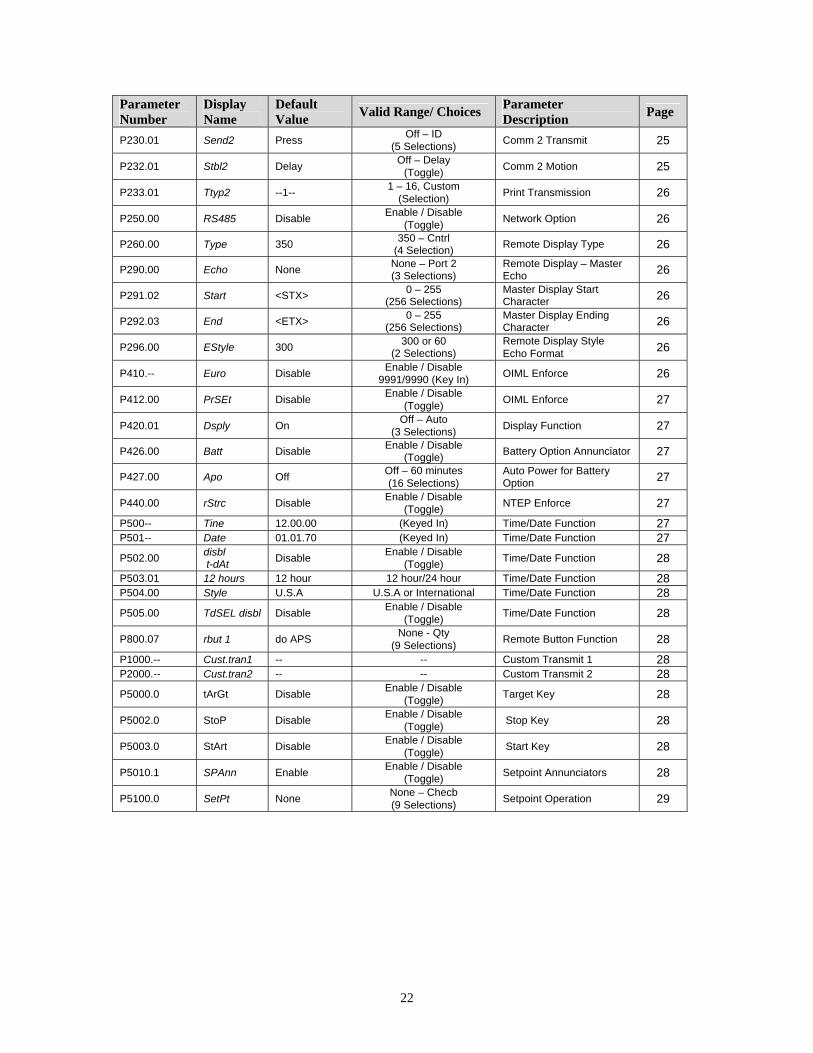
Parameter Number
Display Name
Default Value Valid Range/ Choices Parameter
Description Page
P230.01 Send2 Press Off – ID (5 Selections) Comm 2 Transmit 25
P232.01 Stbl2 Delay Off – Delay (Toggle) Comm 2 Motion 25
P233.01 Ttyp2 --1-- 1 – 16, Custom (Selection) Print Transmission 26
P250.00 RS485 Disable Enable / Disable (Toggle) Network Option 26
P260.00 Type 350 350 – Cntrl (4 Selection) Remote Display Type 26
P290.00 Echo None None – Port 2 (3 Selections)
Remote Display – Master Echo 26
P291.02 Start <STX> 0 – 255 (256 Selections)
Master Display Start Character 26
P292.03 End <ETX> 0 – 255 (256 Selections)
Master Display Ending Character 26
P296.00 EStyle 300 300 or 60 (2 Selections)
Remote Display Style Echo Format 26
P410.-- Euro Disable Enable / Disable 9991/9990 (Key In) OIML Enforce 26
P412.00 PrSEt Disable Enable / Disable (Toggle) OIML Enforce 27
P420.01 Dsply On Off – Auto (3 Selections) Display Function 27
P426.00 Batt Disable Enable / Disable (Toggle) Battery Option Annunciator 27
P427.00 Apo Off Off – 60 minutes (16 Selections)
Auto Power for Battery Option 27
P440.00 rStrc Disable Enable / Disable (Toggle) NTEP Enforce 27
P500-- Tine 12.00.00 (Keyed In) Time/Date Function 27 P501-- Date 01.01.70 (Keyed In) Time/Date Function 27 P502.00 disbl
t-dAt Disable Enable / Disable (Toggle) Time/Date Function 28
P503.01 12 hours 12 hour 12 hour/24 hour Time/Date Function 28 P504.00 Style U.S.A U.S.A or International Time/Date Function 28 P505.00 TdSEL disbl Disable Enable / Disable
(Toggle) Time/Date Function 28
P800.07 rbut 1 do APS None - Qty (9 Selections) Remote Button Function 28
P1000.-- Cust.tran1 -- -- Custom Transmit 1 28 P2000.-- Cust.tran2 -- -- Custom Transmit 2 28 P5000.0 tArGt Disable Enable / Disable
(Toggle) Target Key 28
P5002.0 StoP Disable Enable / Disable (Toggle) Stop Key 28
P5003.0 StArt Disable Enable / Disable (Toggle) Start Key 28
P5010.1 SPAnn Enable Enable / Disable (Toggle) Setpoint Annunciators 28
P5100.0 SetPt None None – Checb (9 Selections) Setpoint Operation 29
23
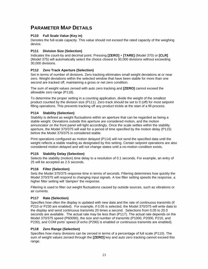
PARAMETER MAP DETAILS P110 Full Scale Value (Key in) Denotes the full-scale capacity. This value should not exceed the rated capacity of the weighing device.
P111 Division Size (Selection) Indicates the count-by and decimal point. Pressing [ZERO] + [TARE] (Model 370) or [CLR] (Model 375) will automatically select the choice closest to 30,000 divisions without exceeding 30,000 divisions.
P112 Zero Track Aperture (Selection) Set in terms of number of divisions. Zero tracking eliminates small weight deviations at or near zero. Weight deviations within the selected window that have been stable for more than one second are tracked off, maintaining a gross or net zero condition.
The sum of weight values zeroed with auto zero tracking and [ZERO] cannot exceed the allowable zero range (P118).
To determine the proper setting in a counting application, divide the weight of the smallest product counted by the division size (P111). Zero track should be set to 0 (off) for most setpoint filling operations. This prevents tracking off any product trickle at the start of a fill process.
P114 Stability (Selection) Stability is defined as weight fluctuations within an aperture that can be regarded as being a stable weight. Deviations outside this aperture are considered motion, and the motion annunciator on the front panel will light accordingly. Once the scale settles within the stability aperture, the Model 370/375 will wait for a period of time specified by the motion delay (P115) before the Model 370/375 is considered stable.
Print operations configured as motion delayed (P114) will not send the specified data until the weight reflects a stable reading as designated by this setting. Certain setpoint operations are also considered motion delayed and will not change states until a no-motion condition exists.
P115 Stability Delay (Selection) Selects the stability (motion) time delay to a resolution of 0.1 seconds. For example, an entry of 25 will be accepted as 2.5 seconds.
P116 Filter (Selection) Sets the Model 370/375 response time in terms of seconds. Filtering determines how quickly the Model 370/375 will respond to changing input signals. A low filter setting speeds the response, a higher filter setting will 'dampen' the response.
Filtering is used to filter out weight fluctuations caused by outside sources, such as vibrations or air currents.
P117 Rate (Selection) Specifies how often the display is updated with new data and the rate of continuous transmits (if P210 or P230 are enabled). For example, if 0.05 is selected, the Model 370/375 will write data to the display and send continuous transmits 20 times a second. Selections from 0.05 to 20.0 seconds are available. The actual rate may be less than (P117). The actual rate depends on the Model 370/375 speed (P60090), the size and number of transmits (P1000, P2000, P210, and P230), and COM ports' speed (if echo (P290) is enabled or continuous transmits are enabled).
P118 Zero Range (Selection) Specifies how many divisions can be zeroed in terms of a percentage of full scale (P110). The sum of weight values zeroed through the [ZERO] key and auto zero tracking cannot exceed this range.

24
A zero range of 5% is commonly used with large tank scales to avoid accidental zeroing of a full or partially full tank.
P119 Multi-Point Linearization (Toggle) Enable the five-point linearization feature used during load cell calibration.
P150 Units (Toggle) Set default units to 'lb', 'kg' or ‘other’ (third unit). The Model 370/375 must use the default units during calibration procedures (see Chapter 4:). The default units are the displayed units upon power-up. If ‘other’ is chosen, P152 must be set to one of the available unit selections.
P151 Units Button (Toggle) When enabled, this parameter will allow [UNITS] to toggle between 'lb', 'kg' (1000g) or third unit. When disabled, the Model 370/375 will show only the calibration units as determined by P150.
P152 Third Unit (Selection) This parameter will allow the choice of three additional units (ounces, grams or lb oz) that may be accessed with the [UNITS] key. Only one unit will be available at a time. The third unit can only be selected if P151 is enabled. The third unit will be identified by an annunciator on the display below the ‘kg’ annunciator.
P161 Tare Save (Toggle) Enabling Tare Save allows the Model 370/375 to retain the tare value in the event of power loss. The correct net weight is restored upon power-up.
P166 Auto Tare (Toggle) When enabled, pressing [TARE] will wait for a no-motion condition and then bring the scale to a net zero reading. Disabling will prevent keypad tare operations.
Note that if a setpoint activation method is set to [TARE], disabling Auto Tare will also disable the activation of that setpoint.
P167 Keyboard Tare (Toggle) If P167 is disabled, then the user cannot view tare using the select key. Also, it will block numeric tare (manually entering tare) and show the message; "Funct" "disbl". The only way you can tare is using the automatic tare (press [TARE] to tare the weight on the scale). When P167 is on, the user can view tare using the select key (tare will follow Net). The unit will accept numeric tare. On the Model 375, a known tare amount may be keyed in with the numeric keypad. On the Model 370, a known tare amount may be keyed in with the [PRINT] and [UNITS] keys.
P169 Auto Tare Clear (Toggle) Enabling this feature will cause the current tare value to be cleared to zero every time the Model 370/375 stabilizes within ±5 graduations of gross zero
P171 Analog (Toggle) Enable or disable the optional analog output module. See Analog Output Setup on page 35 for all parameters associated with the Analog Output Module.
P179 Count (Toggle) When enabled, the quantity mode becomes accessible via the [SAMPLE/Enter] or [SELECT] key. The quantity mode is identified by the illumination of the QTY annunciator.
P200 Baud (Comm 1) (Selection) Set the desired baud rate for the communication port. 150 - 115K bps
P201 Data Bits (Comm 1) (Toggle) Select 7 or 8 data bits for the transmission.

25
P202 Parity (Comm 1) (Selection) Select Odd, Even or None for the transmission parity.
P203 Stop Bits (Comm 1) (Toggle) Select 1 or 2 stop bits for communication port transmissions.
P204 Comm Handshake (Comm 1) (Selection) Select from None, Software (Xon/Xoff), Hardware (CTS/RTS), or Both.
P210 Send (Comm 1) (Selection) Transmission Send options:
Choice Number Selection Name Description P210.00 Off All transmissions disabled. P210.01 Press Sends transmission with [PRINT] key. P210.02 Cont. Sends transmissions continuously.
P210.03 Cycle Send single transmission after weight is reached and motion ceases. Must return display value below 0.1% of F.S. to reset for next transmission.
P210.04 ID Sends transmission with the stored ID.
P212 Send Stability (Comm 1) (Toggle) Enabling Send Stability will delay any transmissions until a no-motion condition exists.
P213 Transmit Selection (Comm 1) (Selection) Select desired print output (1 - 16 or custom). The transmission will be initiated by the selected print operation (P210) and / or the Remote Key selection (P800). See page 29 for details on preset formats or page 31 for details on custom transmit.
P220 Baud (Comm 2) (Selection) Set the desired baud rate for the communication port. 150 - 115K bps
P221 Data Bits (Comm 2) (Toggle) Select 7 or 8 data bits for the transmission.
P222 Parity (Comm 2) (Selection) Select Odd, Even or None for the transmission parity.
P223 Stop Bits (Comm 2) (Toggle) Select 1 or 2 stop bits for communication port transmissions.
P224 Comm Handshake (Comm 2) (Selection) Select from None and Software (Xon/Xoff).
P230 Send (Comm 2) (Selection) Transmission Send options:
Choice Number Selection Name Description P230.00 Off All transmissions disabled. P230.01 Press Sends transmission with [PRINT] key. P230.02 Cont. Sends transmissions continuously.
P230.03 Cycle Send single transmission after weight is reached and motion ceases. Must return display value below 0.1% of F.S. to reset for next transmission.
P230.04 ID Sends transmission with the stored ID.
P232 Send Stability (Comm 2) (Toggle) Enabling Send Stability will delay any transmissions until a no-motion condition exists.
26
P233 Transmit Selection (Comm 2) (Selection) Select desired print output (1 - 16 or custom). The transmission will be initiated by the selected print operation (P210) and / or the Remote Key selection (P800). See page 29 for details on preset formats or page 31 for details on custom transmit.
P250 RS-485 Multi-Drop Network (Toggle) Enable / disable the RS-485 multi-drop network option. Requires that an RS-485 option board be installed. This option allows up to 250 RS-485 devices to be networked together in either a half duplex or full duplex wiring scheme. See the RS-485 Multi-Drop Network Setup and Operation section beginning on page 35 for complete details on RS-485 setup and operation.
P251 Address (Key in) (Only displayed if P250 is enabled) Specifies the address of the Model 370/375 for RS-485 multi-drop communications. Allowed choices are 0 (disabled) and 4 - 254.
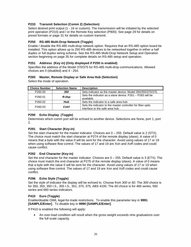
P260 Master, Remote Display or Safe Area Hub (Selection) Select the mode of operation.
P290 Echo Display (Toggle) Determines which comm port will be echoed to another device. Selections are None, port 1, port 2.
P291 Start Character (Key-in) Set the start character for the master indicator. Choices are 0 – 255. Default value is 2 (STX). The choice must match the start character at P274 of the remote display (slave). A value of 0 means that a byte with the value 0 will be sent for the character. Avoid using values of 17 or 19 when using software flow control. The values of 17 and 19 are Xon and Xoff codes and could cause conflict.
P292 End Character (Key-in) Set the end character for the master indicator. Choices are 0 – 255. Default value is 3 (ETX). The choice must match the end character at P275 of the remote display (slave). A value of 0 means that a byte with the value 0 will be sent for the character. Avoid using values of 17 or 19 when using software flow control. The values of 17 and 19 are Xon and Xoff codes and could cause conflict.
P296 Echo Style (Toggle) Set the style of indicator the display will be echoed to. Choose from 300 or 60. The 300 choice is for 350, 355, 350 I.S., 355 I.S., 351, 370, 375, ABS 4100. The 60 choice is for 460 series, 560 series and 660 series indicators.
P410 Euro (Toggle) Enable/disable OIML legal-for-trade restrictions. To enable this parameter key in 9991 [SAMPLE/Enter]. To disable key in 9990 [SAMPLE/Enter].
If P410 is enabled the following will apply:
• An over-load condition will result when the gross weight exceeds nine graduations over the full scale capacity.
Choice Number Selection Name Description P260.00 350 Sets indicator as the master device. Model 350/355/370/375.
P260.01 R-dsp Sets the indicator as a slave device. P261 – P283 will be available.
P260.02 Hub Sets the indicator to a safe area hub.
P260.03 Cntrl Sets the indicator to the master controller for fiber-optic interface to the safe area hub.

27
• Full scale capacity is always referenced from the last zero calibration reference, not the last zero acquired by pressing [ZERO].
P412 Preset Character (Toggle) If P412 is enabled, it will add a ‘P’ to the beginning of the tare parameter on the display and transmits if the last tare value was entered manually by the user (numeric entry). P167 needs to be enabled in order to key in a tare value. A ‘P’ will not be added if the last tare was performed by pressing the tare key or if the tare value is zero (even if the zero value was manually entered by the user). The ‘P’ prefix stands for “Preset”. When P412 is disabled, the unit will never show 'P' before tare no matter how tare is entered.
P420 Display (Selection) Select display control option. Choose from On, Off or Auto. The auto setting helps conserve power for extended battery life. When the Model 370/375 display is off, the load cell(s) are still powered.
If P420 is set to Off or selection 0, you can turn on the display by holding down the [ZERO] key upon power up.
P426 Low Battery Indication (Toggle) Press [TARE] to enable or disable this option from the gross or net modes. Low battery will be indicated continuously if this feature is enabled without the battery option installed.
P427 Battery Option Automatic Shutdown (Selection) Select duration of time for auto shutdown. Selections are off, 0.5, 1, 2, 3, 4, 5, 10, 15, 20, 25, 30, 35, 40, 45, and 60. Choices are in set in minutes.
P440 Legal For Trade Restrictions (Toggle) Enable NTEP legal-for-trade restrictions. The Model 370/375 are not NTEP approved.
If P440 is enabled the following will apply:
• Serial data will not be received while in the Setup Mode. • Received alpha characters will not be displayed. • Numeric tare entries cannot be received through the serial port. • Pressing [TARE] with a gross weight of zero (0) or keying in a tare value of zero (0) will
not automatically switch to the net mode. • Negative tare values are not accepted. • Tare rounding is enforced. • When the tare value is zero, the net mode is not selectable.
P500 Time Setting (key in) Enter the time in the form HH.MM.SS. Time is always shown in military format within this parameter. P503 will determine how the time is displayed in the weigh mode.
P501 Date Setting (key in) Enter the date in the form MM.DD.YY. P504 will determine the how the date is displayed in the weigh mode.
Parameter Setting Choice Description
P420.00 Off Shuts off the display. P420.01 On Normal display operation.
P420.02 Auto Shuts off the display when weight has stabilized within 6 divisions for 5 minutes. Changing weight more than 6 divisions will re-enable the display. NOTE: The display will turn back on if data is received via the RS-232 Port.

28
P502 Time/Date (toggle) Enables or disables the time and date feature. If enabled the time and date will be accessible from the weigh mode with the [SELECT] key. The weight will continue to be updated when viewing the time or date. The time will be formatted as defined by P503 and the date will be formatted as defined by P504. See page 52 for instructions on how to change the time and/or date.
P503 Hours (toggle) Determines the TIME format style, 12 hour or 24 hour. If in 12-hour mode the right most decimal point on the display will become the PM indicator. Note: The time must be entered as military time. If the mode is set for 12-hour, the time will be converted to a 12-hour clock.
P504 Style (toggle) Determines the DATE format style, U.S.A. or Int'l. If set for U.S.A, the date will resemble 01/26/01. If set for international, the date will resemble 26/01/01.
P505 Time/Date Select (toggle) Enables or disables the editing of time and date the weigh mode.
P800 Remote Key 1 Operation (Selection) A physical Remote Key closure does not exist and is not functional on the Model 370/375. The remote key choice for activation within a setpoint will not work.
P1000 Custom Transmit 1 A custom transmit is a user-defined string of data that can be sent to the serial port. Parameter P1000 is the beginning of the custom transmit table for transmit 1and must be enabled for transmit by selecting “cust” at P213. Parameters use three bytes of memory; ASCII characters and control codes use one byte. See P60001 for available memory. The custom transmit cannot be viewed or altered from the Model 370/375. A custom transmit must be entered via the serial port. See Custom Transmit Setup on page 31 for details on designing and loading a custom transmit.
P2000 Custom Transmit 2 A custom transmit is a user-defined string of data that can be sent to the serial port. Parameter P2000 is the beginning of the custom transmit table for transmit 2 and must be enabled for transmit by selecting “cust” at P230. Parameters use three bytes of memory; ASCII characters and control codes use one byte. See P60001 for available memory. The custom transmit cannot be viewed or altered from the Model 370/375. A custom transmit must be entered via the serial port. See Custom Transmit Setup on page 31 for details on designing and loading a custom transmit.
P5000 Target Key (Toggle) Although the target key is not physically on the keypad, a target value can be entered by sending a %<CTRL A> using a serial device such as a computer. P5000 must be enabled and a setpoint that uses a target value must be enabled before the target can be entered in this manner.
P5002 Stop Key (Toggle) Although the stop key is not physically on the keypad, you can stop a setpoint remotely by sending a %<CTRL F> using a serial device such as a computer. P5002 and a setpoint must be enabled before the stop function will operate in this manner.
P5003 Start Key (Toggle) Although the start key is not physically on the keypad, you can start a setpoint remotely by sending a %<CTRL E> using a serial device such as a computer. P5003 and a setpoint must be enabled before the start function will operate in this manner.

29
P5010 Setpoint Annunciators (Toggle) Enables or disables the setpoint annunciators to the left of the main 7-segment display.
P5100 Setpoint Operation (Selection) Sets the desired Setpoint operation. Choose between None, ChecP, Fill, Batch, Discharge, Both, ChecA or Independent. See General Setpoint Setup on page 36 for complete details on setpoint setup and operation.
PPrriinnttiinngg
PRESET TRANSMIT SELECTIONS The Model 370 and Model 375 provide 16 preset formats for printing tickets or sending data to a computer. Only one format or custom transmit may be enabled at a time.
Choice 0 Custom Transmit: User-defined serial data string (see Custom Transmit Setup on page 31). Choice 1 GSE Standard Transmit: HH:MM:SS am MM/DD/YY <CR><LF> (only if P502 is enabled) XXX.XX kg Gross<CR><LF> XXX.XX kg Tare <CR><LF> XXX.XX kg Net <CR><LF> Choice 2 Count: HH:MM:SS am MM/DD/YY <CR><LF> (only if P502 is enabled) XXX Count <CR/LF> XX.X kg APS <CR><LF> XXX.XX kg Gross<CR><LF> XXX.XX kg Tare <CR><LF> XXX.XX kg Net <CR><LF> (NOTE: The time and date will only be printed in choice 1 and 2 if P502 is enabled). Choice 3 (Condec Clone): <STX> <POL> <DATA> <L/K> <G/N> <STAT> <CR> <LF> Where: <STX> is a single control code, decimal value of 2. <DATA> is 8 characters, 1st character is either minus sign or a space, padded with leading spaces, with an embedded decimal point. <L/K> is a single 'L' or 'K' character to indicate lb or kg units. <G/N> is a single 'G' or 'N' character to indicate gross or net data. <STAT> is an 'O' (overload/underload), 'M' (motion), or space otherwise. <CR> is a single control code (carriage return), decimal value of 13. <LF> is a single control code (line feed), decimal value of 10. Choice 4: <STX><SignedDATA><sp><lb/kg><sp><Gross/Net/Qty><STAT><CR> Choice 5: <STX><Signed DATA><sp><lb/kg><STAT><CR> Choice 6: <STX><Signed DATA><sp><lb/kg><CR>

30
Choice 7: <STX><Unsigned DATA><sp><CR> Choice 8: <STX><Signed DATA><sp><lb/kg><sp><Gross/Net/Qty><STAT><SPS><CR> Choice 9: <STX><Signed DATA><sp><lb/kg><STAT><SPS><CR> Choice 10: <STX><Signed Displayed Weight><sp><lb/kg><SPS><CR> Choice 11: <STX><Unsigned Displayed Weight><SPS><CR> Choice 12: <STX><Unsigned DATA><sp><lb/kg><sp><Gross/Net/Qty><STAT><CR>
Use choice 12 to send to a 450/455/550 remote display that is set to text mode and a <CR> terminator. Choice 13: <STX><Unsigned DATA><sp><lb/kg><sp><Gross/Net/Qty><STAT> <CR><LF> Choice 14 (Simulates NCI 3835): <LF>Signed DATA<CR><LF><STAT><CR><ETX>
Data Block Name Description <STX> A single control code, decimal value of 2. <ETX> A single control code, decimal value of 3. <POL> A <space> for positive data or a - for negative data. <Signed DATA> 8 characters right justified, space padded, including a decimal point and polarity sign.
Polarity is a ‘+’ or ‘–‘ to the immediate left of the most significant digit. <Unsigned DATA> 8 characters right justified, space padded, including a decimal point. <lb/kg> Two characters indicating pounds or kilograms. <Gross/Net/QTY> Single word for gross weight, net weight or quantity. <STAT> An 'O' (overload/underload), 'M' (motion), or <space> otherwise <SPS> See <SPS> Setpoint Status below. <CR> A single control code, decimal value of 13. <LF> A single control code, decimal value of 10. <sp> ASCII Space, decimal value of 32.
<SPS> Setpoint Status
Transmitting the setpoint status will reflect the current state of all the setpoints, regardless of which setpoint operation is configured. The status can be read as a single ASCII numeric character (0-7), a Hex value (30h-37h) or a binary bit comparison. Status is preceded by a <space> and an "S". The preceding data stream format is for fixed transmissions of <SPS> as specified above. This is not associated with the custom transmission of parameter P96.
SP 1 SP 2 SP3 ASCII Hex Bit Comparison Off Off Off 0 30h 0011 0000 On Off Off 1 31h 0011 0001 Off On Off 2 32h 0011 0010 On On Off 3 33h 0011 0011 Off Off On 4 34h 0011 0100 On Off On 5 35h 0011 0101 Off On On 6 36h 0011 0110 On On On 7 37h 0011 0111
31
Choice 15 (RSD 3000): <STX><G>< Signed DATA ><lb/kg><CR><LF> <STX><SPS><CR><LF>
Choice 16 (RSD 3000): <STX><N>< Signed DATA ><lb/kg><CR><LF> <STX><SPS><CR><LF>
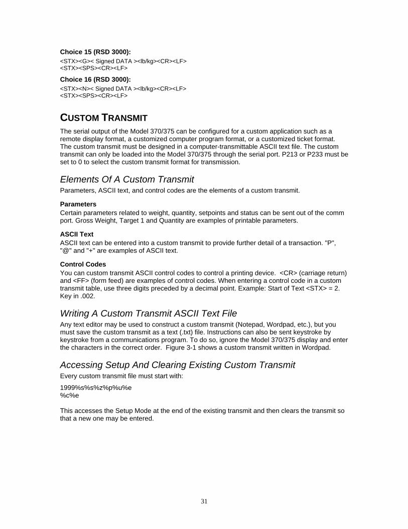
CUSTOM TRANSMIT The serial output of the Model 370/375 can be configured for a custom application such as a remote display format, a customized computer program format, or a customized ticket format. The custom transmit must be designed in a computer-transmittable ASCII text file. The custom transmit can only be loaded into the Model 370/375 through the serial port. P213 or P233 must be set to 0 to select the custom transmit format for transmission.
Elements Of A Custom Transmit Parameters, ASCII text, and control codes are the elements of a custom transmit.
Parameters Certain parameters related to weight, quantity, setpoints and status can be sent out of the comm port. Gross Weight, Target 1 and Quantity are examples of printable parameters.
ASCII Text ASCII text can be entered into a custom transmit to provide further detail of a transaction. "P", "@" and "+" are examples of ASCII text.
Control Codes You can custom transmit ASCII control codes to control a printing device. <CR> (carriage return) and <FF> (form feed) are examples of control codes. When entering a control code in a custom transmit table, use three digits preceded by a decimal point. Example: Start of Text <STX> = 2. Key in .002.
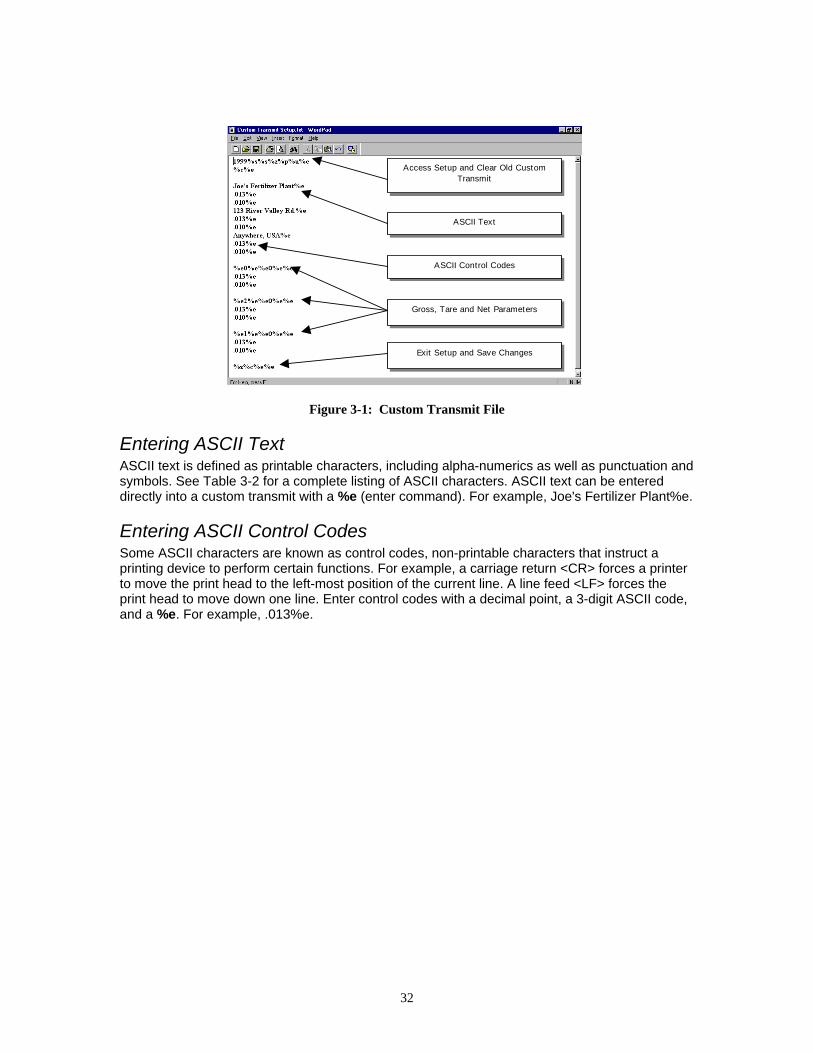
Writing A Custom Transmit ASCII Text File Any text editor may be used to construct a custom transmit (Notepad, Wordpad, etc.), but you must save the custom transmit as a text (.txt) file. Instructions can also be sent keystroke by keystroke from a communications program. To do so, ignore the Model 370/375 display and enter the characters in the correct order. Figure 3-1 shows a custom transmit written in Wordpad.
Accessing Setup And Clearing Existing Custom Transmit Every custom transmit file must start with:
1999%s%s%z%p%u%e %c%e This accesses the Setup Mode at the end of the existing transmit and then clears the transmit so that a new one may be entered.
32
Figure 3-1: Custom Transmit File
Entering ASCII Text ASCII text is defined as printable characters, including alpha-numerics as well as punctuation and symbols. See Table 3-2 for a complete listing of ASCII characters. ASCII text can be entered directly into a custom transmit with a %e (enter command). For example, Joe's Fertilizer Plant%e.
Entering ASCII Control Codes Some ASCII characters are known as control codes, non-printable characters that instruct a printing device to perform certain functions. For example, a carriage return <CR> forces a printer to move the print head to the left-most position of the current line. A line feed <LF> forces the print head to move down one line. Enter control codes with a decimal point, a 3-digit ASCII code, and a %e. For example, .013%e.
Access Setup and Clear Old Custom Transmit
ASCII Text
ASCII Control Codes
Gross, Tare and Net Parameters
Exit Setup and Save Changes

33
Table 3-2: ASCII / HEXADECIMAL CONVERSION CHART HEX CHAR DEC
00 NUL 000 1A SUB 026 34 4 052 N 078 68 h 104
01 SOH 001 1B ESC 027 35 5 053 4F O 079 69 i 105
02 STX 002 1C FS 028 36 6 054 50 P 080 6A j 106
03 ETX 003 1D GS 029 37 7 055 51 Q 081 6B k 107
04 EOT 004 1E RS 030 38 8 056 52 R 082 6C l 108
05 ENQ 005 1F US 031 39 9 057 53 S 083 6D m 109
06 ACK 006 20 SP 032 3A : 058 54 T 084 6E n 110
07 BEL 007 21 ! 033 3B ; 059 55 U 085 6F o 111
08 BS 008 22 “ 034 3C < 060 56 V 086 70 p 112
09 HT 009 23 # 035 3D = 061 57 W 087 71 q 113
0A LF 010 24 $ 036 3E > 062 58 X 088 72 r 114
0B VT 011 25 % 037 3F ? 063 59 Y 089 73 s 115
0C FF 012 26 & 038 40 @ 064 5A Z 090 74 t 116
0D CR 013 27 ‘ 039 41 A 065 5B [ 091 75 u 117
0E SO 014 28 ( 040 42 B 066 5C \ 092 76 v 118
0F SI 015 29 ) 041 43 C 067 5D ] 093 77 w 119
10 DLE 016 2A * 042 44 D 068 5E ^ 094 78 x 120
11 DC1 017 2B + 043 45 E 069 5F _ 095 79 y 121
12 DC2 018 2C ‘ 044 46 F 070 60 ` 096 7A z 122
13 DC3 019 2D - 045 47 G 071 61 a 097 7B { 123
14 DC4 020 2E . 046 48 H 072 62 b 098 7C | 124
15 NAK 021 2F / 047 49 I 073 63 c 099 7D } 125
16 SYN 022 30 0 048 4A J 074 64 d 100 7E ~ 126
17 ETB 023 31 1 049 4B K 075 65 e 101 7F DEL 127
18 CAN 024 32 2 050 4C L 076 66 f 102
19 EM 025 33 3 051 4D M 077 67 g 103
Most printers require a carriage return (.013) and/or a line feed (.010) to print preceding data and avoid leaving data in the printer buffer. See Table 3-2 for a list of ASCII codes.

34
Parameter Selection Numbers The following sequence enters parameters into a custom transmit: %e , the parameter number, %e%e , a format code, and then %e%e with no intervening spaces.
%e 0 %e%e 0 %e%e
Initiates Parameter Entry
Parameter Number (Table 3-3)
Enters Parameter and Initiates Format Entry
Format Choice (Table 3-4)
Enters Format and Ends Entry
Table 3-3: Custom Transmit Parameter Selection Numbers Parameter Name Parameter Number Sample Print Output
Gross Weight 0 27.49 lb Gross Net Weight 1 14.53 lb Net Tare Weight 2 12.96 lb Tare Time / Date 11 10:01:01 am 01/26/01 ID 21 ID: 12MN53 Quantity 30 58 Qty APW 34 0.25 lb APW APW * K 35 250 lb APW * K Targ1 60 400 lb Targ1 Targ2 64 500 lb Targ2 Targ3 66 1000 lb Targ3 Act 1 (note: Indp. SP1) 70 600 lb Act 1 Rst 1 (note: Indp. SP1) 71 10 lb Rst 1 Act 2 (note: Indp. SP2) 72 300 lb Act 2 Rst 2 (note: Indp. SP2) 73 10 lb Rst 2 Act 3 (note: Indp. SP3) 74 100 lb Act 3 Rst 3 (note: Indp. SP3) 75 5 lb Rst 3 Setpoint Status 96 Setpt 0 Stability Status 97 Stat M Displayed Value 98 16.34 lb Gross
The default format code for all parameters is 0. This prints all numeric data with 8 characters, right justified, left spaces filled., the units (if applicable) and the parameter name. The format choices for all parameters (except Stability Status and Setpoint Status) are shown in Table 3-4.
Table 3-4: Custom Transmit Format Codes Choice Sample Print Result Description Weight Parameter Format Codes 0 “ 27.49 lb Gross” Fixed width (8 characters), right justified, left spaces filled. 1 “000027.49 lb Gross” Fixed width (8 characters), right justified, left zeroes filled. 2 “27.49 lb Gross” Fixed width, left justified, right spaces filled. 3 “27.49 lb Gross” Minimum possible width. 8 “400. lb Net” Print decimal point, even if data has no fractional portion. 16 “+400 lb Net” Print “+” for positive numbers. 32 “336.52 Net” Do NOT print parameter units (lb or kg). 64 “336.52 lb Net” Print value in “default” units (as opposed to current viewed units). 128 “336.52 lb” Do NOT print parameter name. Only Format Code that applies to ID Time/Date Format Codes 1 “10:07:40 am 01/26/01 Includes seconds with time. 2 “10:08 01/26/01” 24 hour time format. 4 “10:11 am Jan 26, 2001” Print date spelled out. 8 “10:12 am Fri 01/26/01” Print day of the week. 16 “10:12 am 26/01/01” International date format. 32 “980503984 Tm/Dt” # of seconds since 12:00 AM Jan 1, 1970. 64 “01/26/01” Do NOT print time. 128 “10:14 am” Do NOT print date.
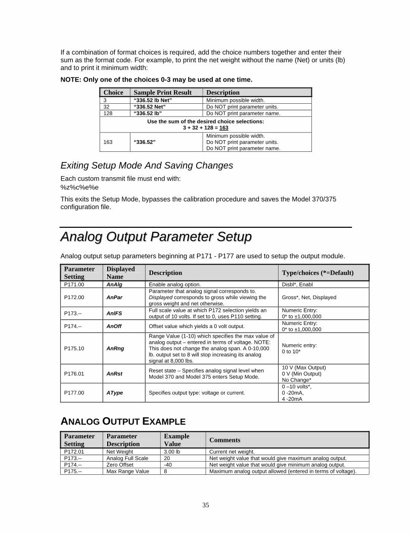
35
If a combination of format choices is required, add the choice numbers together and enter their sum as the format code. For example, to print the net weight without the name (Net) or units (lb) and to print it minimum width:
NOTE: Only one of the choices 0-3 may be used at one time.
Choice Sample Print Result Description 3 “336.52 lb Net” Minimum possible width. 32 “336.52 Net” Do NOT print parameter units. 128 “336.52 lb” Do NOT print parameter name.
Use the sum of the desired choice selections: 3 + 32 + 128 = 163
163 “336.52” Minimum possible width. Do NOT print parameter units. Do NOT print parameter name.
Exiting Setup Mode And Saving Changes Each custom transmit file must end with: %z%c%e%e
This exits the Setup Mode, bypasses the calibration procedure and saves the Model 370/375 configuration file.
AAnnaalloogg OOuuttppuutt PPaarraammeetteerr SSeettuupp Analog output setup parameters beginning at P171 - P177 are used to setup the output module.
Parameter Setting
Displayed Name Description Type/choices (*=Default)
P171.00 AnAlg Enable analog option. Disbl*, Enabl
P172.00 AnPar Parameter that analog signal corresponds to. Displayed corresponds to gross while viewing the gross weight and net otherwise.
Gross*, Net, Displayed
P173.-- AnlFS Full scale value at which P172 selection yields an output of 10 volts. If set to 0, uses P110 setting.
Numeric Entry: 0* to ±1,000,000
P174.-- AnOff Offset value which yields a 0 volt output. Numeric Entry: 0* to ±1,000,000
P175.10 AnRng
Range Value (1-10) which specifies the max value of analog output – entered in terms of voltage. NOTE: This does not change the analog span. A 0-10,000 lb. output set to 8 will stop increasing its analog signal at 8,000 lbs.
Numeric entry: 0 to 10*
P176.01 AnRst Reset state – Specifies analog signal level when Model 370 and Model 375 enters Setup Mode.
10 V (Max Output) 0 V (Min Output) No Change*
P177.00 AType Specifies output type: voltage or current. 0 –10 volts*, 0 -20mA, 4 -20mA
ANALOG OUTPUT EXAMPLE Parameter Setting
Parameter Description
Example Value Comments
P172.01 Net Weight 3.00 lb Current net weight. P173.-- Analog Full Scale 20 Net weight value that would give maximum analog output. P174.-- Zero Offset -40 Net weight value that would give minimum analog output. P175.-- Max Range Value 8 Maximum analog output allowed (entered in terms of voltage).

36
Since 7.166 Volts is less than 8 Volts (per P175), the output signal is not restricted and would be 7.166 Volts.
If a current output is selected, the output is a milli-amp current where 0 volts corresponds to either 0 mA or 4 mA (as per P177) and 10 volts would translate to 20 mA. Values in between would be scaled proportionately:
Analog signal resolution: the output is the result of a 16 bit conversion resulting in a resolution of 1 part in 65535 or 10 / 65535 = 0.00015 V.
SSeettppooiinntt CCoonnffiigguurraattiioonn The Model 370/375 has several pre-programmed scale setpoint applications available at P5100. Various related setpoint parameters may appear according to which of the standard programs is chosen. Refer to the chart below for available setpoint operations.
Setpoint Selection Function Description Page Ref
P5100.00 None Setpoints disabled.
P5100.01 ChecP Percentage check-weighing. Over/Under tolerances are based on a percentage of the target weight. 39
P5100.02 Fill Single Ingredient Fill (Single or Dual-Speed). Allows the use of pre-acts for dribble feed and compensation for free-fall material. Includes a selectable ‘learn’ mode.
40
P5100.03 Batch Batch up to three ingredients. Allows for the use of pre-acts to compensate for free-fall material. Includes selectable ‘learn’ modes. 41
P5100.04 Dschg Single Ingredient Discharge (Single or Dual-Speed). Allows the use of pre-acts for dribble feed and compensation for free-fall material. Includes a selectable ‘learn’ mode.
43
P5100.05 Both
Single Ingredient Fill and Discharge. Fill large holding vessels and discharge material in pre-determined amounts. Allows for the use of pre-acts to compensate for free-fall material. Includes a selectable ‘learn’ mode.
45
P5100.06 ChecA Absolute check-weighing. Over/Under tolerances are based on discrete values. 46
P5100.07 Indep Independent Setpoints. Activation based on specific target values. Includes selectable reset conditions. 47
P5100.08 Checb Target Deviation check-weighing. Over/Under tolerances are deviated from the target weight. 49
Each program utilizes the three annunciators located to the left of the main display to give a visual status of the setpoint. A setpoint option board may be installed to allow control of an external device (see Setpoint Card Connections on page 12).
* 10 = 7.166 v* 10 = 3 - (-40)
20 - (-40)
43
60Vout =
Iout = 16 * 7.166
10
(20 mA - 4mA) * 7.166 v
10 v + 4 = 15.465 mA + 4 mA =

37
ACTIVATION METHODS (GENERAL) Setpoint activation for Fill, Batch, Discharge, and Both can be initiated in one of two ways: Tare or Auto. Check-weigh operations have no start function. Independent setpoint operations are limited to Above or Below activation. The Model 370 and Model 375 setpoint option board may be connected in-series with a larger automated control system or a manually activated switching device. A foot switch, a two-hand safety station, or other permissive-start devices may be used for safety or system compatibility.
Activation Method Description Tare Operation [TARE] activates the setpoint. It waits for a no-motion condition, then tares scale to net zero.
The appropriate setpoint is then activated. Remote Key The [REMOTE KEY] closure does not exist on the Model 370/375. Do not use
this choice. Auto-Start Automatically activates the setpoint. It waits for a no-motion condition, then adds
the target to the current displayed weight to achieve a relative cutoff value.
Pre-Acts (General) Pre-Acts are control actions prior to reaching a desired target value. Necessary to prevent over-filling due to product flow rate, relay and valve response time and product suspension, Pre-Acts and other system variables affect how much more product reaches the weighing device after the Model 370/375 has deactivated a setpoint.
Pre-act 1 Used in dual-speed applications, pre-act 1 specifies when the 370/375 should switch from fast-fill to slow-fill, allowing the system to perform the bulk of a filling operation as quickly as possible before switching to a more manageable dribble mode for final cutoff. When using a single-speed device, set pre-act 1 to 0.
Pre-act 2 Specifies the weight where the final cutoff should occur, enabling the 370/375 to compensate for a dispensing control's closure time and account for free-fall material. Free-fall is the amount of product that has passed the point of the dispensing control yet not yet reached the weighing device.
Pre-act values are entered in terms of the amount of product that would over-fill or 'how early' to close the control device. For instance, after repeated tests, a system consistently over-fills by .5 lbs. This is the value that should be entered as the pre-act. The 370/375 would then deactivate the setpoint .5 lbs. less than the desired final target value.
Parameter Setting Actual Cutoff Value Comments Target = 400 lbs. Desired final weight. Pre-Act 1 = 28 400 – 28 = 372 Switch to slow feed at 372 lbs. Pre-Act 2 = .5 400 – 0.5 = 399.5 Final fill valve closes at 399.5 lbs.
Learn Feature (General) The Model 370/375 can 'learn' optimal pre-act values. When enabled, the learn feature will automatically adjust the final cutoff value based on an analysis of the five previous fills, helping achieve a final target by compensating for product viscosity, changes in plant air pressures, sticky valves, etc. For each cycle, the prior five final weights are analyzed and a new pre-act value is calculated.
Pause Feature (General) The Model 370/375 can pause setpoint operations. This is useful as a safety device, for mid-cycle operator breaks, mechanical adjustments, etc.

38
When invoked, Pause deactivates all setpoints. The display will show: “Tare= ~ Abort”. Pressing [TARE] will abort the current cycle; any other keypress will resume the cycle. The Pause feature has four settings:
Pause Setting Action Result Disabled Pause feature disabled.
Keypad 370/375 Key Press Current cycle paused – all setpoints deactivated.
Remote Key Do not use
Both 370/375 Key Press OR Remote Key Contact Closure
Current cycle paused – all setpoints deactivated.
Changing Targets From The Weigh Mode (General) When a setpoint operation is configured from the Setup Mode, certain parameters are made available in the Weigh Mode. Pressing [SELECT] cycles through available modes (Gross, Net, Quantity, Targ 1, etc.).
When viewing a setpoint-related parameter from the Weigh Mode, [TARE] takes on a special function. Data keyed in prior to [TARE] will be displayed as the new setpoint parameter value. Pressing [TARE] alone will advance to the first subset for the current setpoint parameter. Pre-acts and tolerances are subsets of their respective target values.
A negative target value many be entered for the independent setpoints only. To enter the negative sign press [PRINT] then [PRINT] + [UNITS] (Model 370) or [TARE] (Model 375). A negative sign will be displayed. Press [TARE] to continue with the entry
Programs that involve a discharge cycle are loss-in-weight type applications. Any target or pre-act values for these programs should be entered as positive numbers. The Model 370/375 will automatically interpret these values as negative.
Example (General) The target for the fill setpoint operation is Targ 1. This is a setpoint-related parameter and automatically becomes an available mode when Fill is configured in the setpoint setup. Pre-act 1 and pre-act 2 are subsets of Targ 1. The following procedure illustrates how to change a target from 25 lbs to 40 lbs., keep pre-act 1 at 2 lbs. and change pre-act 2 from .15 lbs to .05 lbs.
To change targets from the Weigh Model (370 and 375):
1. Press [SELECT]. DISPLAY READS 0.00 2. Press [SELECT] to view the current fill target. DISPLAY READS Targ1 ~ 25 3. Press 40 [TARE] to set a new fill target of 40 lbs. DISPLAY READS Targ1 ~ 40 4. Press [TARE] to select the Pre-Act 1 (subset) value of 2 lbs. DISPLAY READS PA 1 ~ 2 5. Press [TARE] to select the Pre-Act 2 (subset) value of .15 lbs. DISPLAY READS PA 2 ~ .15 6. Press .05 [TARE] to select a new Pre-Act 2 value of .05 lbs. DISPLAY READS PA 2 ~ .05 7. Press [SELECT] to display the current Gross Weight.

39
PERCENTAGE CHECK-WEIGHING This feature is commonly used in check-weigh applications. After a target weight is entered, upper and lower tolerances are entered as a percentage of the target. Over and under tolerance values are automatically calculated according to the percentages entered. The desired target may be based on gross weight, net weight or quantity (if counting is enabled).
Table 3-5: Setpoint Setup (Percentage Check-Weighing) Setpoint Selection Function Description
P5100.1 ChecP Check-weigh by percentage. P5101.-- Targ1 Absolute target value. P5102.-- PctLo Low acceptance percentage. P5103.-- PctHi High acceptance percentage. P5104.0 Based Select from Net, Gross or Quantity.
See Key-In Parameters on page 18 for instructions on entering data using the front panel keys.
Setpoint Activation (Percentage Check-Weighing) In order for the annunciators to activate, the displayed value must be at least five graduations above zero.
Check-Weigh Status Annunciator Status Annunciator Color OVER SP 1 Illuminated Red GOOD SP 2 Illuminated Green UNDER SP 3 Illuminated Yellow
Changing Targets From The Weigh Mode (Percentage Check-Weighing) When Check-Weigh by Percentage is configured in the setpoint setup, the Targ 1 value automatically becomes an available mode for the [SELECT] key. Keying in a value before pressing [TARE] changes Targ 1. Targ 1 is entered as an absolute value. Pressing [TARE] alone gives access to the subsets. PctLo and PctHi are the subsets for Targ 1. PctLo and PctHi are entered as percentage values.
To change targets from the Weigh Mode:
1. Press [SELECT]. DISPLAY READS 0.00
2. Press [SELECT] to view the current target. DISPLAY READS Targ1 ~ 18
3. Press 40 [TARE] to set a new target of 40 lbs. DISPLAY READS Targ1 ~ 40
4. Press [TARE] or [SAMPLE/Enter] to select the Percent low (subset) value. Key in the desired value (example: 2) and press [TARE] or [SAMPLE/Enter]. DISPLAY READS PctLo ~2
5. Press [TARE] to select the Percent hi (subset) value of .5 lb. Key in the desired value (example: 5) and press [TARE] or [SAMPLE/Enter]. DISPLAY READS PctHi ~ 5
6. Press [SELECT] to display the current Gross Weight.
The Pre-Acts, Learn Mode, and Pause Feature options are not applicable to check-weigh operation.

40
Example (Percentage Check-Weighing) With a system set up to check-weigh ice cream containers, the following settings might be used to guarantee container weights from 4.95 to 5.10 lbs.:
Parameter Setting Acceptable Check-weigh Values Comments Target = 5.00 Desired container weight. Percent Lo Value = 1 5.00 * .01 (1 %) = 0.05 Low acceptable range = 4.95 to 5.00. Percent Hi Value = 2 5.00 * .02 (2 %) = 0.1 High acceptable range = 5.00 to 5.10.
FILL The fill program is used for single-speed or dual-speed filling operations. The dual-speed fill operation allows for both a fast and a slow fill mode. During a fast-fill, setpoints 1 and 2 are activated. During a slow-fill or single-speed fill, only setpoint 1 is activated.
Table 3-6: Setpoint Setup (Fill) Setpoint Selection Function Description P5100.2 Fill Select Fill Setpoint Operation P5101.-- Targ1 Final Fill Target Value P5104.0 Based Select between Net or Quantity P5105.-- PA 1 Pre-Act 1 Value (Fast-to-Slow Value; 0 for Single-Speed) P5107.0 Start 1 Setpoint Activation Method P5109.-- PA 2 Pre-Act 2 Value (Final Cutoff) P5110.1 Learn 2 Learn Feature for Pre-Act 2 P5114.1 PrAc 1 Pre-Act 1 Available as Subset in Weigh Mode P5115.1 PrAc 2 Pre-Act 2 Available as Subset in Weigh Mode P5116.1 Pause Keypad Press invokes Pause
See Key-In Parameters on page 18 for instructions on using the front panel keys for entering data.
Activation Method (Fill) The fill begins with the selected activation method. The deactivation of the setpoints is automatic. The desired target may be based on net or quantity (if counting is enabled). See Activation Methods (General) on page 37 for activation details.
Fill Status Annunciator Status Setpoint Status (Requires Setpoint Option Board)
Fast Fill SP 1 & SP 2 Illuminated Relay 1 and Relay 2 Contacts Closed Dribble Fill (or Single-Speed Fill) SP 1 Illuminated Relay 1 Contacts Closed Fill Done or Pause SP 1 & SP 2 Off Relay 1 and Relay 2 Contacts Open
Pre-Acts (Fill) Pre-act 1 is used for dual-speed filling. Pre-act 1 specifies when the Model 370/375 should switch from fast-fill to slow-fill. When using a single-speed device, pre-act 1 should be set to 0 from the Setup Mode. P5114 should also be disabled to prevent pre-act 1 from appearing as a subset of target in the Weigh Mode.
Pre-act 2 specifies the target where the final cutoff should occur, regardless of a single-speed or dual-speed operation.
Pre-act 1 controls setpoint 2. Pre-act 2 controls setpoint 1.
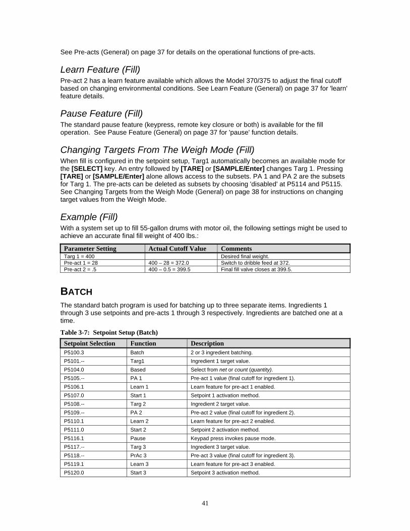
41
See Pre-acts (General) on page 37 for details on the operational functions of pre-acts.
Learn Feature (Fill) Pre-act 2 has a learn feature available which allows the Model 370/375 to adjust the final cutoff based on changing environmental conditions. See Learn Feature (General) on page 37 for 'learn' feature details.
Pause Feature (Fill) The standard pause feature (keypress, remote key closure or both) is available for the fill operation. See Pause Feature (General) on page 37 for 'pause' function details.
Changing Targets From The Weigh Mode (Fill) When fill is configured in the setpoint setup, Targ1 automatically becomes an available mode for the [SELECT] key. An entry followed by [TARE] or [SAMPLE/Enter] changes Targ 1. Pressing [TARE] or [SAMPLE/Enter] alone allows access to the subsets. PA 1 and PA 2 are the subsets for Targ 1. The pre-acts can be deleted as subsets by choosing 'disabled' at P5114 and P5115. See Changing Targets from the Weigh Mode (General) on page 38 for instructions on changing target values from the Weigh Mode.
Example (Fill) With a system set up to fill 55-gallon drums with motor oil, the following settings might be used to achieve an accurate final fill weight of 400 lbs.:
Parameter Setting Actual Cutoff Value Comments Targ 1 = 400 Desired final weight. Pre-act 1 = 28 400 – 28 = 372.0 Switch to dribble feed at 372. Pre-act 2 = .5 400 – 0.5 = 399.5 Final fill valve closes at 399.5.
BATCH The standard batch program is used for batching up to three separate items. Ingredients 1 through 3 use setpoints and pre-acts 1 through 3 respectively. Ingredients are batched one at a time.
Table 3-7: Setpoint Setup (Batch) Setpoint Selection Function Description P5100.3 Batch 2 or 3 ingredient batching. P5101.-- Targ1 Ingredient 1 target value. P5104.0 Based Select from net or count (quantity). P5105.-- PA 1 Pre-act 1 value (final cutoff for ingredient 1). P5106.1 Learn 1 Learn feature for pre-act 1 enabled. P5107.0 Start 1 Setpoint 1 activation method. P5108.-- Targ 2 Ingredient 2 target value. P5109.-- PA 2 Pre-act 2 value (final cutoff for ingredient 2). P5110.1 Learn 2 Learn feature for pre-act 2 enabled. P5111.0 Start 2 Setpoint 2 activation method. P5116.1 Pause Keypad press invokes pause mode. P5117.-- Targ 3 Ingredient 3 target value. P5118.-- PrAc 3 Pre-act 3 value (final cutoff for ingredient 3). P5119.1 Learn 3 Learn feature for pre-act 3 enabled. P5120.0 Start 3 Setpoint 3 activation method.

42
See Key-In Parameters on page 18 for instructions on using the front panel keys for entering data.
Activation Method (Batch) The filling of each ingredient begins when one of three selectable start functions occur. Each ingredient may have its own start function. The deactivation of the setpoint is automatic. The desired targets may be based on net weight or quantity (if counting is enabled). All ingredients must be based on the same parameter. See Activation Methods (General) on page 37 for details on activation methods.
Batch Status Annunciator Status Setpoint Status (Requires Setpoint Option Board) Fill 1 SP 1 Illuminated Relay 1 Contacts Closed,
Relay 2 and 3 Contacts Open
Fill 2 SP 2 Illuminated Relay 2 Contacts Closed, Relay 1 and3 Contacts Open
Fill 3 SP 3 Illuminated Relay 3 Contacts Closed, Relay 1 and 2 Contacts Open
Pre-Acts (Batch) Pre-acts 1, 2 and 3 specify the final cutoff for each respective ingredient. See Per-acts (General) on page 37 for pre-act details.
Learn Feature (Batch) Each batch pre-act has the learn feature available which allows the Model 370/375 to automatically adjust the final cutoff based on changing environmental conditions. See Learn Feature (General) on page 37 for 'learn' feature details.
Pause Feature (Batch) The standard pause feature (keypress, remote key closure or both) is available for the batch operation. See Pause Feature (General) on page 37 for 'pause' details.
Changing Targets From The Weigh Mode (Batch) When batch is configured in the setpoint setup, Targ1 automatically becomes an available mode for the [SELECT] key. An entry followed by [TARE] or [SAMPLE/Enter] changes Targ 1. Pressing [TARE] or [SAMPLE/Enter] alone allows access to the subsets. PA 1 and PA 2 are the subsets for Targ 1. The pre-acts can be deleted as subsets by choosing 'disabled' at P5114 and P5115. See Changing Targets from the Weigh Mode (General) on page 38 for instructions on changing target values from the Weigh Mode.
Pre-acts 1 and 2 are always available as subsets of their respective targets from the Weigh Mode.
Example (Batch) With a system set up a system to make a 50,000 lb batch with water (30,000 lbs.), corn syrup (15,000 lbs.) and caramel color (5,000 lbs.), ingredient 1 should start with [TARE] and subsequent ingredients should auto-start.
Parameter Setting Actual Cutoff Value Comments Target 1 = 30,000 Desired water weight. Based = Net Targets are compared to net weight.
Pre-Act 1 = 100 30,000 – 100 = 29,900 Water valve closes at 29,900 lbs. Free-fall will bring weight to 30,000.
Learn 1 = Enabled Analyze previous five fills and auto-adjust pre-act 1.
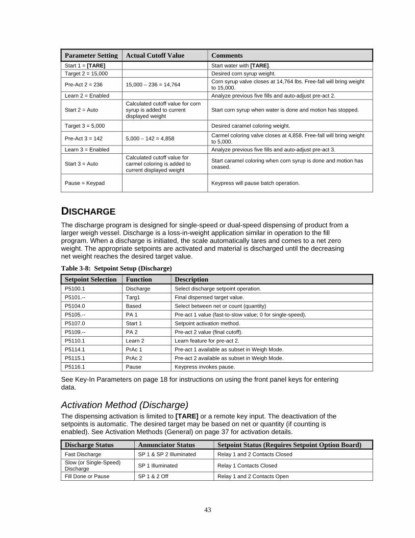
43
Parameter Setting Actual Cutoff Value Comments Start 1 = [TARE] Start water with [TARE]. Target 2 = 15,000 Desired corn syrup weight.
Pre-Act 2 = 236 15,000 – 236 = 14,764 Corn syrup valve closes at 14,764 lbs. Free-fall will bring weight to 15,000.
Learn 2 = Enabled Analyze previous five fills and auto-adjust pre-act 2.
Start 2 = Auto Calculated cutoff value for corn syrup is added to current displayed weight
Start corn syrup when water is done and motion has stopped.
Target 3 = 5,000 Desired caramel coloring weight.
Pre-Act 3 = 142 5,000 – 142 = 4,858 Carmel coloring valve closes at 4,858. Free-fall will bring weight to 5,000.
Learn 3 = Enabled Analyze previous five fills and auto-adjust pre-act 3.
Start 3 = Auto Calculated cutoff value for carmel coloring is added to current displayed weight
Start caramel coloring when corn syrup is done and motion has ceased.
Pause = Keypad Keypress will pause batch operation.
DISCHARGE The discharge program is designed for single-speed or dual-speed dispensing of product from a larger weigh vessel. Discharge is a loss-in-weight application similar in operation to the fill program. When a discharge is initiated, the scale automatically tares and comes to a net zero weight. The appropriate setpoints are activated and material is discharged until the decreasing net weight reaches the desired target value.
Table 3-8: Setpoint Setup (Discharge) Setpoint Selection Function Description P5100.1 Discharge Select discharge setpoint operation. P5101.-- Targ1 Final dispensed target value. P5104.0 Based Select between net or count (quantity) P5105.-- PA 1 Pre-act 1 value (fast-to-slow value; 0 for single-speed). P5107.0 Start 1 Setpoint activation method. P5109.-- PA 2 Pre-act 2 value (final cutoff). P5110.1 Learn 2 Learn feature for pre-act 2. P5114.1 PrAc 1 Pre-act 1 available as subset in Weigh Mode. P5115.1 PrAc 2 Pre-act 2 available as subset in Weigh Mode. P5116.1 Pause Keypress invokes pause.
See Key-In Parameters on page 18 for instructions on using the front panel keys for entering data.
Activation Method (Discharge) The dispensing activation is limited to [TARE] or a remote key input. The deactivation of the setpoints is automatic. The desired target may be based on net or quantity (if counting is enabled). See Activation Methods (General) on page 37 for activation details.
Discharge Status Annunciator Status Setpoint Status (Requires Setpoint Option Board) Fast Discharge SP 1 & SP 2 Illuminated Relay 1 and 2 Contacts Closed Slow (or Single-Speed) Discharge SP 1 Illuminated Relay 1 Contacts Closed
Fill Done or Pause SP 1 & 2 Off Relay 1 and 2 Contacts Open

44
Pre-Acts (Discharge) Pre-act 1 is used for dual-speed dispensing. Pre-act 1 specifies when the system should switch from fast-discharge to slow-discharge. When using a single-speed device, pre-act 1 should be set to 0 from the Setup Mode. P5114 should also be disabled to prevent pre-act 1 from appearing as a subset of the target in the Weigh Mode. Pre-act 2 specifies the point where the final cutoff should occur, regardless of a single-speed or dual-speed operation. See Pre-acts (General) on page 37 for details on the operational functions of pre-acts.
Pre-act 1 controls setpoint 2. Pre-act 2 controls setpoint 1.
Learn Feature (Discharge) Pre-act 2 has the learn feature available which allows the Model 370/375 to automatically adjust the final cutoff based on changing environmental conditions. See Learn Feature (General) on page 37 for learn feature details.
Pause Feature (Discharge) The standard pause feature (keypress, remote key closure or both) is available for the discharge operation. See Pause Feature (General) on page 37 for pause function details.
When Discharge is configured in the setpoint setup, Targ1 automatically becomes an available mode for the [SELECT] key. An entry followed by [TARE] or [SAMPLE] changes Targ 1. Pressing [TARE] or [SAMPLE] alone allows access to the subsets. PA 1 and PA 2 are the subsets for Targ 1. The pre-acts can be deleted as subsets by choosing 'disabled' at P5114 and P5115. See Changing Targets from the Weigh Mode (General) on page 38 for instructions on changing target values from the Weigh Mode.
Target and pre-act values are entered as positive values.
If the total amount of product in the weigh vessel is less than the entered target, the Model 370/375 will prompt “Tare ~ =Cont”. Pressing [TARE] will dispense whatever is left in the vessel. Pressing any other key will abort the discharge cycle to allow for refilling the vessel.
Example (Discharge) With a system set up to dispense ball bearings from a 50,000 lb weigh-bin and the fast-feed requiring an early cutoff to slow-feed, the following settings might be used to achieve accurate dispensing of 1000 bearings:
Parameter Setting Actual Cutoff Value Comments Targ 1 = 1000 0 – 1000 = (-1000) Desired quantity (decreasing value from a net zero: enter as
a positive value). Based = Qty Targets are compared to quantity (P170 Enabled).
PA 1 = 200 1000 – 200 = 800 0 – 800 = (-800)
Switch to slow feed at –800 bearings (decreasing value from a net zero: enter as a positive value).
Start = [TARE] Start discharge with [TARE].
PA 2 = 15 1000 – 15 = 985 0 – 985 = (-985)
Final gate begins closing at 985 bearings. Delayed closure brings final quantity to 1000 (decreasing value from a net zero: enter as a positive value).
Learn 2 = Enabled Analyze five previous operations and auto-adjust Pre-Act 2. PrAc 1 = Enabled Pre-act 1 available as subset of Targ 1 in Weigh Mode.
PrAc 2 = Disabled Pre-act 2 NOT available as subset of Targ 1 in Weigh Mode (auto-adjust only).
Pause – Remote Remote key closure invokes Pause.

45
BOTH The 'Both' program combines a fill operation with a discharge operation. This automates a single-speed vessel filling operation with a single-speed multiple dispensing function. Setpoint 1 is used for filling the vessel and Setpoint 2 is used for product discharge. The 'both' program uses values for two targets and two pre-acts. Both targets must be based alike (net or quantity, quantity if count is selected).
Table 3-9: Setpoint Setup (Both) Setpoint Selection Function Description P5100.5 Both Select both setpoint operation. P5101.-- Targ1 Vessel fill target value. P5104.0 Based Select from Net or Count (Quantity). P5105.-- PA 1 Pre-act 1 value for vessel fill. P5106.1 Learn 1 Learn feature for pre-act 1. P5107.0 Start 1 Setpoint 1 activation method. P5108.-- Targ 2 Vessel discharge target value. P5109.-- PA 2 Pre-act 2 value for vessel discharge. P5110.1 Learn 2 Learn feature for pre-act 2. P5111.0 Start 2 Setpoint 2 activation method. P5116.1 Pause Keypad press invokes pause.
See Key-In Parameters on page 18 for instructions on using the front panel keys for entering data.
Activation Method (Both) The fill and discharge functions begin with their selected activation methods. The deactivation of the setpoints is automatic. The desired target may be based on net or quantity (if counting is enabled). See Activation Methods (General) on page 37 for activation details.
Both Status Annunciator Status Setpoint Status (Requires Setpoint Option Board) Vessel Fill SP 1 Illuminated Relay 1 Contacts Closed Vessel Discharge SP 2 Illuminated Relay 2 Contacts Closed Fill Done or Pause SP 1 & SP 2 Off Relay 1 and Relay 2 Contacts Open
Pre-Acts (Both) Pre-act 1 is used for vessel filling. Pre-act 1 specifies the point where the final cutoff for the fill should occur. Pre-act 2 specifies the point where the final cutoff for the material discharge should occur. See Pre-acts (General) on page 37 for details on the operational functions of pre-acts.
Learn Feature (Both) Both pre-act 1 and 2 have the learn feature available which allows the Model 370/375 to automatically adjust the final cutoff based on changing environmental conditions. See Learn Feature (General) on page 37 for 'learn' feature details.
Pause Feature (Both) The standard pause feature (keypress, remote key closure or both) is available for the Both operation. See Pause Feature (General) on page 37 for 'pause' functions details.
Pre-act 1 controls setpoint 1. Pre-act 2 controls setpoint 2.
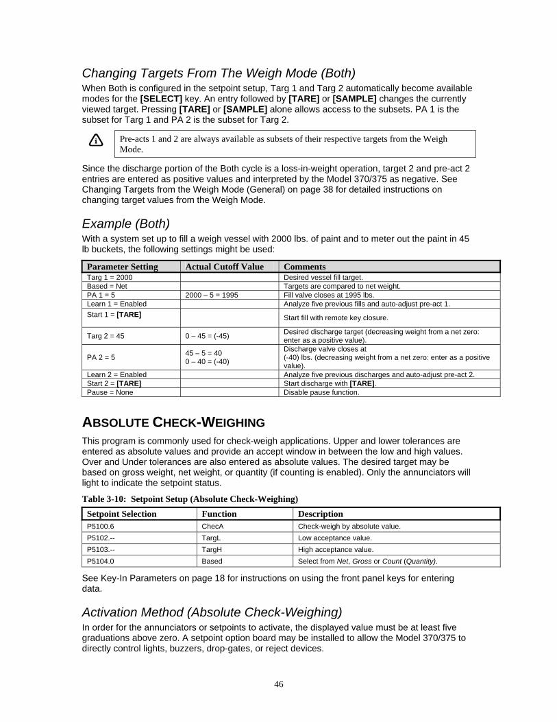
46
Changing Targets From The Weigh Mode (Both) When Both is configured in the setpoint setup, Targ 1 and Targ 2 automatically become available modes for the [SELECT] key. An entry followed by [TARE] or [SAMPLE] changes the currently viewed target. Pressing [TARE] or [SAMPLE] alone allows access to the subsets. PA 1 is the subset for Targ 1 and PA 2 is the subset for Targ 2.
Pre-acts 1 and 2 are always available as subsets of their respective targets from the Weigh Mode.
Since the discharge portion of the Both cycle is a loss-in-weight operation, target 2 and pre-act 2 entries are entered as positive values and interpreted by the Model 370/375 as negative. See Changing Targets from the Weigh Mode (General) on page 38 for detailed instructions on changing target values from the Weigh Mode.
Example (Both) With a system set up to fill a weigh vessel with 2000 lbs. of paint and to meter out the paint in 45 lb buckets, the following settings might be used:
Parameter Setting Actual Cutoff Value Comments Targ 1 = 2000 Desired vessel fill target. Based = Net Targets are compared to net weight. PA 1 = 5 2000 – 5 = 1995 Fill valve closes at 1995 lbs. Learn 1 = Enabled Analyze five previous fills and auto-adjust pre-act 1. Start 1 = [TARE]
Start fill with remote key closure.
Targ 2 = 45 0 – 45 = (-45) Desired discharge target (decreasing weight from a net zero: enter as a positive value).
PA 2 = 5 45 – 5 = 40 0 – 40 = (-40)
Discharge valve closes at (-40) lbs. (decreasing weight from a net zero: enter as a positive value).
Learn 2 = Enabled Analyze five previous discharges and auto-adjust pre-act 2. Start 2 = [TARE] Start discharge with [TARE]. Pause = None Disable pause function.
ABSOLUTE CHECK-WEIGHING This program is commonly used for check-weigh applications. Upper and lower tolerances are entered as absolute values and provide an accept window in between the low and high values. Over and Under tolerances are also entered as absolute values. The desired target may be based on gross weight, net weight, or quantity (if counting is enabled). Only the annunciators will light to indicate the setpoint status.
Table 3-10: Setpoint Setup (Absolute Check-Weighing) Setpoint Selection Function Description P5100.6 ChecA Check-weigh by absolute value. P5102.-- TargL Low acceptance value. P5103.-- TargH High acceptance value. P5104.0 Based Select from Net, Gross or Count (Quantity).
See Key-In Parameters on page 18 for instructions on using the front panel keys for entering data.
Activation Method (Absolute Check-Weighing) In order for the annunciators or setpoints to activate, the displayed value must be at least five graduations above zero. A setpoint option board may be installed to allow the Model 370/375 to directly control lights, buzzers, drop-gates, or reject devices.

47
Check-Weigh Status Annunciator Status Annunciator Color (LED) OVER SP 1 Illuminated Red GOOD SP 2 Illuminated Green UNDER SP 3 Illuminated Yellow
The Pre-Acts, Learn Mode, and Pause Feature options are not applicable to check-weigh operation.
Changing Targets From The Weigh Mode (Absolute Check-Weighing) When Check-Weigh by Absolute is configured in the setpoint setup, the Targ 1 value automatically becomes an available mode for the [SELECT] key. Keying in a value before pressing [TARE] changes Targ 1. Targ 1 is entered as an absolute value. Pressing [TARE] or [SAMPLE/Enter] alone gives access to the subsets. Lo and Hi are the subsets for Targ 1. Lo and Hi are also entered as absolute values.
To change targets from the Weigh Mode:
1. Press [SELECT]. DISPLAY READS 0.00
2. Press [SELECT] to view the current target. DISPLAY READS Targ1 ~ 18
3. Press 25 [TARE] or [SAMPLE/Enter] to set a new target of 25 lbs. DISPLAY READS Targ1 ~ 25
4. Press [TARE] or [SAMPLE/Enter] to select the low (subset) value. Key in the desired value (example: 23.5) and press [TARE] or [SAMPLE/Enter]. DISPLAY READS Lo ~23.5
5. Press [TARE] or [SAMPLE/Enter] to select the high (subset) value. Key in the desired value (example: 25.75) and press [TARE] or [SAMPLE/Enter]. DISPLAY READS Hi ~ 25.75
6. Press [SELECT] to display the current Gross Weight.
Example (Absolute Check-Weighing) With a system set up to check-weigh 50 lb. cement bags, the following settings might be used check-weigh bag from 49.5 to 51.5 lbs.:
Parameter Setting Acceptable Check-Weigh Values Comments Target = 50.00 Desired bag weight.
Low Value = 49.50 49.50 – 50.00 lbs. Low acceptable range = 49.50 to 50.00 lbs.
High Value = 51.50 50.00 – 51.50 lbs. High acceptable range = 50.00 to 51.50 lbs.
INDEPENDENT SETPOINT OPERATION Independent Setpoints allow controlling setpoints when the gross, net or quantity (if counting is enabled) is above or below a target value. The reset (deactivation) choice of each setpoint is selectable from Tare, Remote Key, Auto, Non-latching or Absolute. See Key-In Parameters on page 18 for instructions on using front panel keys for data entry.
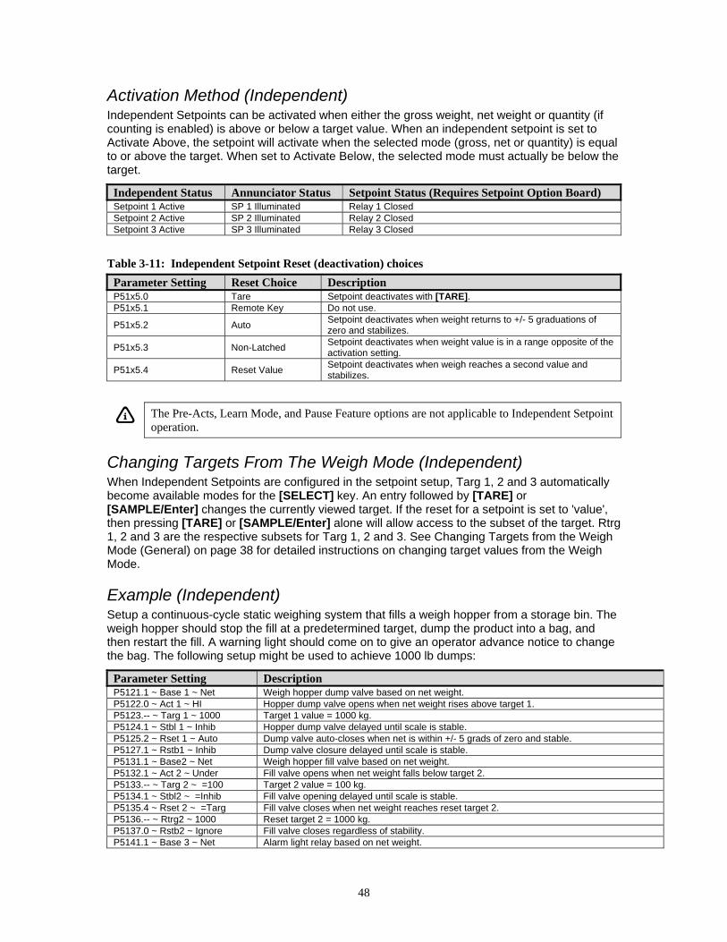
48
Activation Method (Independent) Independent Setpoints can be activated when either the gross weight, net weight or quantity (if counting is enabled) is above or below a target value. When an independent setpoint is set to Activate Above, the setpoint will activate when the selected mode (gross, net or quantity) is equal to or above the target. When set to Activate Below, the selected mode must actually be below the target.
Independent Status Annunciator Status Setpoint Status (Requires Setpoint Option Board) Setpoint 1 Active SP 1 Illuminated Relay 1 Closed Setpoint 2 Active SP 2 Illuminated Relay 2 Closed Setpoint 3 Active SP 3 Illuminated Relay 3 Closed
Table 3-11: Independent Setpoint Reset (deactivation) choices Parameter Setting Reset Choice Description P51x5.0 Tare Setpoint deactivates with [TARE]. P51x5.1 Remote Key Do not use.
P51x5.2 Auto Setpoint deactivates when weight returns to +/- 5 graduations of zero and stabilizes.
P51x5.3 Non-Latched Setpoint deactivates when weight value is in a range opposite of the activation setting.
P51x5.4 Reset Value Setpoint deactivates when weigh reaches a second value and stabilizes.
The Pre-Acts, Learn Mode, and Pause Feature options are not applicable to Independent Setpoint operation.
Changing Targets From The Weigh Mode (Independent) When Independent Setpoints are configured in the setpoint setup, Targ 1, 2 and 3 automatically become available modes for the [SELECT] key. An entry followed by [TARE] or [SAMPLE/Enter] changes the currently viewed target. If the reset for a setpoint is set to 'value', then pressing [TARE] or [SAMPLE/Enter] alone will allow access to the subset of the target. Rtrg 1, 2 and 3 are the respective subsets for Targ 1, 2 and 3. See Changing Targets from the Weigh Mode (General) on page 38 for detailed instructions on changing target values from the Weigh Mode.
Example (Independent) Setup a continuous-cycle static weighing system that fills a weigh hopper from a storage bin. The weigh hopper should stop the fill at a predetermined target, dump the product into a bag, and then restart the fill. A warning light should come on to give an operator advance notice to change the bag. The following setup might be used to achieve 1000 lb dumps:
Parameter Setting Description P5121.1 ~ Base 1 ~ Net Weigh hopper dump valve based on net weight. P5122.0 ~ Act 1 ~ HI Hopper dump valve opens when net weight rises above target 1. P5123.-- ~ Targ 1 ~ 1000 Target 1 value = 1000 kg. P5124.1 ~ Stbl 1 ~ Inhib Hopper dump valve delayed until scale is stable. P5125.2 ~ Rset 1 ~ Auto Dump valve auto-closes when net is within +/- 5 grads of zero and stable. P5127.1 ~ Rstb1 ~ Inhib Dump valve closure delayed until scale is stable. P5131.1 ~ Base2 ~ Net Weigh hopper fill valve based on net weight. P5132.1 ~ Act 2 ~ Under Fill valve opens when net weight falls below target 2. P5133.-- ~ Targ 2 ~ =100 Target 2 value = 100 kg. P5134.1 ~ Stbl2 ~ =Inhib Fill valve opening delayed until scale is stable. P5135.4 ~ Rset 2 ~ =Targ Fill valve closes when net weight reaches reset target 2. P5136.-- ~ Rtrg2 ~ 1000 Reset target 2 = 1000 kg. P5137.0 ~ Rstb2 ~ Ignore Fill valve closes regardless of stability. P5141.1 ~ Base 3 ~ Net Alarm light relay based on net weight.
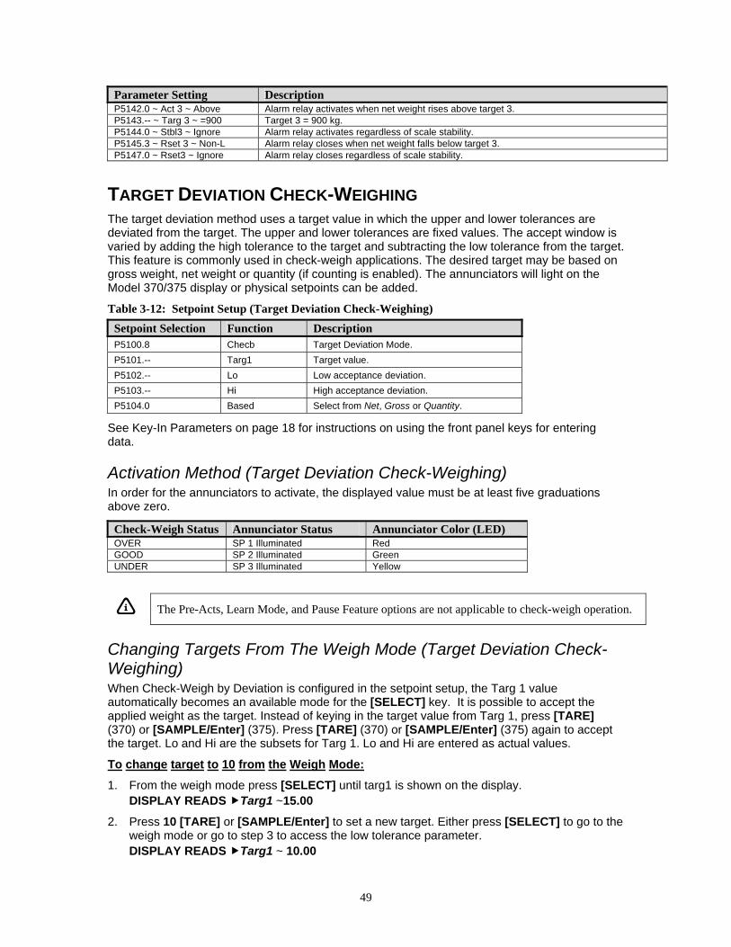
49
Parameter Setting Description P5142.0 ~ Act 3 ~ Above Alarm relay activates when net weight rises above target 3. P5143.-- ~ Targ 3 ~ =900 Target 3 = 900 kg. P5144.0 ~ Stbl3 ~ Ignore Alarm relay activates regardless of scale stability. P5145.3 ~ Rset 3 ~ Non-L Alarm relay closes when net weight falls below target 3. P5147.0 ~ Rset3 ~ Ignore Alarm relay closes regardless of scale stability.
TARGET DEVIATION CHECK-WEIGHING The target deviation method uses a target value in which the upper and lower tolerances are deviated from the target. The upper and lower tolerances are fixed values. The accept window is varied by adding the high tolerance to the target and subtracting the low tolerance from the target. This feature is commonly used in check-weigh applications. The desired target may be based on gross weight, net weight or quantity (if counting is enabled). The annunciators will light on the Model 370/375 display or physical setpoints can be added.
Table 3-12: Setpoint Setup (Target Deviation Check-Weighing) Setpoint Selection Function Description P5100.8 Checb Target Deviation Mode. P5101.-- Targ1 Target value. P5102.-- Lo Low acceptance deviation. P5103.-- Hi High acceptance deviation. P5104.0 Based Select from Net, Gross or Quantity.
See Key-In Parameters on page 18 for instructions on using the front panel keys for entering data.
Activation Method (Target Deviation Check-Weighing) In order for the annunciators to activate, the displayed value must be at least five graduations above zero.
Check-Weigh Status Annunciator Status Annunciator Color (LED) OVER SP 1 Illuminated Red GOOD SP 2 Illuminated Green UNDER SP 3 Illuminated Yellow
The Pre-Acts, Learn Mode, and Pause Feature options are not applicable to check-weigh operation.
Changing Targets From The Weigh Mode (Target Deviation Check-Weighing) When Check-Weigh by Deviation is configured in the setpoint setup, the Targ 1 value automatically becomes an available mode for the [SELECT] key. It is possible to accept the applied weight as the target. Instead of keying in the target value from Targ 1, press [TARE] (370) or [SAMPLE/Enter] (375). Press [TARE] (370) or [SAMPLE/Enter] (375) again to accept the target. Lo and Hi are the subsets for Targ 1. Lo and Hi are entered as actual values.
To change target to 10 from the Weigh Mode:
1. From the weigh mode press [SELECT] until targ1 is shown on the display. DISPLAY READS Targ1 ~15.00
2. Press 10 [TARE] or [SAMPLE/Enter] to set a new target. Either press [SELECT] to go to the weigh mode or go to step 3 to access the low tolerance parameter. DISPLAY READS Targ1 ~ 10.00
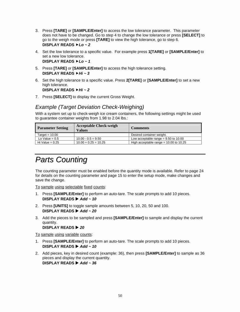
50
3. Press [TARE] or [SAMPLE/Enter] to access the low tolerance parameter. This parameter does not have to be changed. Go to step 4 to change the low tolerance or press [SELECT] to go to the weigh mode or press [TARE] to view the high tolerance, go to step 6. DISPLAY READS Lo ~ 2
4. Set the low tolerance to a specific value. For example press 1[TARE] or [SAMPLE/Enter] to set a new low tolerance. DISPLAY READS Lo ~ 1
5. Press [TARE] or [SAMPLE/Enter] to access the high tolerance setting. DISPLAY READS Hi ~ 3
6. Set the high tolerance to a specific value. Press 2[TARE] or [SAMPLE/Enter] to set a new high tolerance. DISPLAY READS Hi ~ 2
7. Press [SELECT] to display the current Gross Weight.
Example (Target Deviation Check-Weighing) With a system set up to check-weigh ice cream containers, the following settings might be used to guarantee container weights from 1.98 to 2.04 lbs.:
Parameter Setting Acceptable Check-weigh Values Comments
Target = 10.00 Desired container weight. Lo Value = 0.5 10.00 - 0.5 = 9.50 Low acceptable range = 9.50 to 10.00 Hi Value = 0.25 10.00 + 0.25 = 10.25 High acceptable range = 10.00 to 10.25
PPaarrttss CCoouunnttiinngg The counting parameter must be enabled before the quantity mode is available. Refer to page 24 for details on the counting parameter and page 15 to enter the setup mode, make changes and save the change.
To sample using selectable fixed counts:
1. Press [SAMPLE/Enter] to perform an auto-tare. The scale prompts to add 10 pieces. DISPLAY READS Add ~ 10
2. Press [UNITS] to toggle sample amounts between 5, 10, 20, 50 and 100. DISPLAY READS Add ~ 20
3. Add the pieces to be sampled and press [SAMPLE/Enter] to sample and display the current quantity. DISPLAY READS 20
To sample using variable counts:
1. Press [SAMPLE/Enter] to perform an auto-tare. The scale prompts to add 10 pieces. DISPLAY READS Add ~ 10
2. Add pieces, key in desired count (example: 36), then press [SAMPLE/Enter] to sample as 36 pieces and display the current quantity. DISPLAY READS Add ~ 36
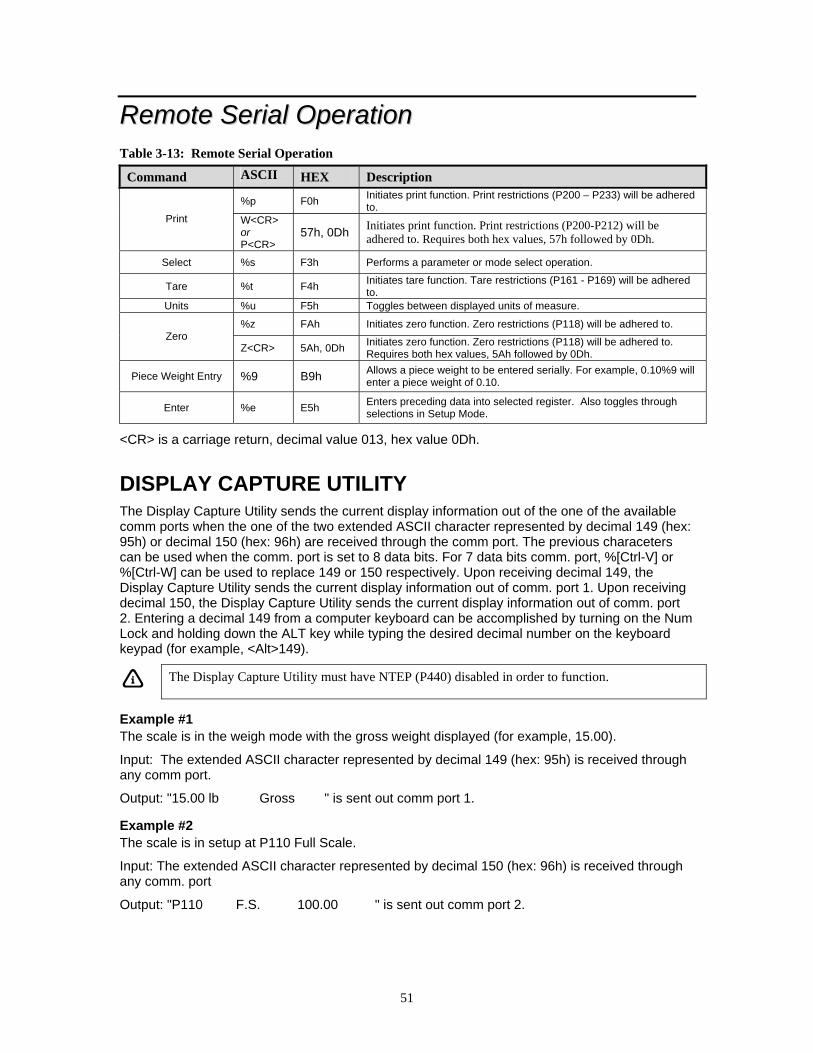
51
RReemmoottee SSeerriiaall OOppeerraattiioonn Table 3-13: Remote Serial Operation
Command ASCII HEX Description
%p F0h Initiates print function. Print restrictions (P200 – P233) will be adhered to.
Print W<CR> or P<CR>
57h, 0Dh Initiates print function. Print restrictions (P200-P212) will be adhered to. Requires both hex values, 57h followed by 0Dh.
Select %s F3h Performs a parameter or mode select operation.
Tare %t F4h Initiates tare function. Tare restrictions (P161 - P169) will be adhered to.
Units %u F5h Toggles between displayed units of measure.
%z FAh Initiates zero function. Zero restrictions (P118) will be adhered to. Zero
Z<CR> 5Ah, 0Dh Initiates zero function. Zero restrictions (P118) will be adhered to. Requires both hex values, 5Ah followed by 0Dh.
Piece Weight Entry %9 B9h Allows a piece weight to be entered serially. For example, 0.10%9 will enter a piece weight of 0.10.
Enter %e E5h Enters preceding data into selected register. Also toggles through selections in Setup Mode.
<CR> is a carriage return, decimal value 013, hex value 0Dh.
DISPLAY CAPTURE UTILITY The Display Capture Utility sends the current display information out of the one of the available comm ports when the one of the two extended ASCII character represented by decimal 149 (hex: 95h) or decimal 150 (hex: 96h) are received through the comm port. The previous characeters can be used when the comm. port is set to 8 data bits. For 7 data bits comm. port, %[Ctrl-V] or %[Ctrl-W] can be used to replace 149 or 150 respectively. Upon receiving decimal 149, the Display Capture Utility sends the current display information out of comm. port 1. Upon receiving decimal 150, the Display Capture Utility sends the current display information out of comm. port 2. Entering a decimal 149 from a computer keyboard can be accomplished by turning on the Num Lock and holding down the ALT key while typing the desired decimal number on the keyboard keypad (for example, <Alt>149).
The Display Capture Utility must have NTEP (P440) disabled in order to function.
Example #1 The scale is in the weigh mode with the gross weight displayed (for example, 15.00).
Input: The extended ASCII character represented by decimal 149 (hex: 95h) is received through any comm port.
Output: "15.00 lb Gross " is sent out comm port 1.
Example #2 The scale is in setup at P110 Full Scale.
Input: The extended ASCII character represented by decimal 150 (hex: 96h) is received through any comm. port
Output: "P110 F.S. 100.00 " is sent out comm port 2.
52
TTiimmee aanndd DDaattee SSeettuupp ((MMooddeell 337700)) The time and date feature is stored as non-volatile (time/date setting will not be lost when the unit power is reset). The time/date parameter is available in the first two fixed transmits (See Transmit Selection on page 29) and can be included in a custom transmit (See Custom Transmit Setup on page 31).
The time and date can be accessed from the weigh mode with the [SELECT] key if P502 is enabled. Also 11%s can be sent into the comm port to access the time/date entry regardless of P502.
The time and date can be entered in the setup mode at P500 and P501. Access P500 to change the time or P501 to change the date. To access the setup mode see page 15. Use the instructions below to enter the time and/or date. Refer to page 19 to save the time and date and exit to the weigh mode.
To enter the date in the setup mode or weigh mode
EXAMPLE: 01.09.04 (January 9, 2004)
1. Press [PRINT] to toggle through the numbers to enter the month. DISPLAY READS 1
2. Press [UNITS] twice to move the decimal point over to separate the month from the day. It is not necessary to enter a 0 before a single digit month. If it is a double-digit entry, press [UNITS] once to move the cursor and then [PRINT] to scroll through the digits. DISPLAY READS 1.
3. Press [PRINT] to toggle through the numbers to enter the day. DISPLAY READS 1.9
4. Press [UNITS] twice to move the decimal point over to separate the day from the year. It is not necessary to enter a 0 before a single digit month. If it is a double-digit entry, press [UNITS] once to move the cursor and then [PRINT] to scroll through the digits. DISPLAY READS 1.9.
5. Press [PRINT] to toggle through the numbers to enter the year. DISPLAY READS 1.9.0
6. Press [UNITS] once to move the cursor and then press [PRINT] to scroll through the digits. DISPLAY READS 1.9.04
7. Press [TARE] twice to accept the entry. DISPLAY READS 01.09.04
To enter the time in the setup mode or weigh mode
EXAMPLE: 16.32.41 (4:32:41 P.M.)
1. Press [PRINT] to toggle through the numbers to enter the hour. Hours must be entered as military time. DISPLAY READS 1
2. Press [UNITS] once to move the cursor. Press [PRINT] to select the next digit. DISPLAY READS 16
3. Press [UNITS] twice to move the decimal point over to separate the hour from the minutes. It is not necessary to enter a 0 before a single digit hour. DISPLAY READS 16.
4. Press [PRINT] to toggle through the numbers to enter the minutes.

53
DISPLAY READS 16.3
5. Press [UNITS] once to move the cursor. Press [PRINT] to select the next digit. DISPLAY READS 16.32
6. Press [UNITS] twice to move the decimal point over to separate the minutes from the seconds. DISPLAY READS 16.32.
7. Press [PRINT] to toggle through the numbers to enter the seconds. The seconds do not have to be entered. Press [TARE] to bypass entering the seconds. DISPLAY READS 16.32.4
8. Press [UNITS] once to move the cursor. Press [PRINT] to select the next digit. DISPLAY READS 16.32.41
9. Press [TARE] twice to accept the time entry. The date and time are now saved until power to the Model 370/375 is lost. The display will be returned to the weigh mode. DISPLAY READS 0.00
TTiimmee aanndd DDaattee SSeettuupp ((MMooddeell 337755)) The time and date feature is stored as non-volatile (time/date setting will not be lost when the unit power is reset). The time/date parameter is available in the first two fixed transmits (See Transmit Selection on page 29) and can be included in a custom transmit (See Custom Transmit Setup on page 31).
The time and date can be accessed from the weigh mode with the [SELECT] key if P502 is enabled. Also 11%s can be sent into the comm port to access the time/date entry or 11 [SELECT] from the weigh mode.
The time and date can be entered in the same fashion as described below. Access P500 to change the time or P501 to change the date. To access the setup mode see page 16.
To enter the date in the setup mode or weigh mode
EXAMPLE: 01.09.04 (January 9, 2004) 1. Key in the date in the following format: 1.9.4
DISPLAY READS 01.09.04
2. Press [SAMPLE/Enter] to except the date and move to the time entry. Press [SAMPLE/Enter] again to bypass the time entry.
To enter the time in the setup mode or weigh mode
EXAMPLE: 16.32.41 (4:32:41 P.M.) 1. Key in the date in the following format: 16.32.41
DISPLAY READS 16.32.41
2. Press [SAMPLE/Enter] to except the time and move to the weigh mode.
UUppggrraaddee MMooddeell 337700//337755 FFiirrmmwwaarree The Model 370 and Model 375 have flash memory on the main board where the parameters are stored. It is possible to update the firmware simply by using a computer. The firmware is loaded into a flash memory IC. This allows for ease in loading firmware updates.
54
The flash memory on the main processor is only rated to be reflashed up to 10 times under extreme industrial and temperature conditions.
PREPARE FOR UPGRADE Before the Model 370/375 firmware can be updated, the procedure below must be followed. A computer with a serial port or USB port is required for loading a flash file. If you are using a USB port, a USB to serial converter is necessary.
1. Connect the communication cable from the computer to comm. 1 of the Model 370 or Model 375.
2. Open a communications program or terminal window program (such as Communication Plus) on the computer.
3. Set the protocol of the Model 370/375 to be 9600 baud, 1 stop bit, no parity. 4. Go to parameter 65020 (re-flash) and press [TARE] (Model 370) or [SAMPLE/Enter] (Model
375). Press [TARE] (Model 370) or [SAMPLE/Enter] (Model 375) at the "ARE YOU SURE ? prompt. Press [TARE] (Model 370) or [SAMPLE/Enter] (Model 375) at the Enter = Flash prompt.
~ Or ~
Unplug the Model 370/375 and move Reflash jumper (E2) from NORMAL to REFLASH. 5. The terminal program should show:
GSE Scale Systems Division of SPX 300 Series Bootloader Version XX (where XX should be at least 03)
Date (where Date should be at least Feb 2004) a. Erase Flash b. Program Flash c. Set Baud Rate d. Quit
6. Typically the default baud rate on the computer will be 9600. The programming time at 9600 baud is about 6 minutes. At 38400 baud the programming time is about one minute and a half. At 57600 baud the programming time is about one minute. Set the Model 370/375 baud rate in the terminal software to the desired baud rate by entering c from the computer keyboard. Set the baud rate of the terminal program to match the baud rate chosen for the Model 370/375.
LOAD FLASH FILE 1. The current flash file must be erased. Enter an a from the computer keyboard. When finished
the menu choices will be replicated. 2. To program flash, enter a b from the computer keyboard. Open the flash file from your
terminal window and send it to the Model 370/375. After the file loads the menu choices will be replicated.
3. To end the flash process, enter a d from the computer keyboard to quit. The Model 370/375 will restart.
4. If the Reflash jumper (E2) was set to REFLASH, unplug the Model 370/375 and return the jumper to the NORMAL position.
In order to enable the Model 375 keypad you must cycle power and hold the [SAMPLE/Enter] key on power up.

55
RReemmoottee DDiissppllaayy CCoonnffiigguurraattiioonn The remote display function allows a master unit (370 or 375) to be echoed to another unit (350 I.S., 355 I.S., 350, 355) and be used in a remote location. There are certain parameters that must be set in order to have the master and slave units communicate together. Refer to the section below to configure the master and remote (slave) units.
MASTER TO REMOTE (SLAVE) CONFIGURATION The remote unit will receive continuous transmission from the master unit. It is necessary to setup the protocol parameters in both units so they match in order to coordinate the transmission. See Table 3-14 for the common protocol parameters. A remote unit will not show the bargraph even if it is a LCD display.
Table 3-14: Common Settings for the Master and Remote Units Master Remote Parameter Description P200 or P220 P200 or P220 Baud rate P201 or P221 P201 or P221 Data bits P202 or P222 P202 or P222 Parity P203 or P223 P203 or P223 Stop bits P204 or P224 P204 or P224 Handshaking P291 P274 Start Character P292 P275 End Character
To enter the master or remote setup (local setup) It is possible to make changes to the master unit setup mode from either the remote unit or the master unit itself. The master unit setup mode can be entered from either the master or the remote units. However, the remote unit (slave) setup mode can ONLY be entered from the remote unit. After in the setup mode, you can make changes from the remote unit or the master unit.
To enter the master unit or remote unit (local unit) setup mode (370, 350, 350 I.S. or 355 I.S., 375):
[ZERO] + [SELECT] [SELECT], [ZERO], [PRINT], [UNITS], [TARE]
or
23640 [SAMPLE/Enter] (Model 355 or 375)
After the setup mode is entered, the numeric portion on the 375 keypad is restored. When in the remote (slave) setup, all annunciators are illuminated on the remote to distingush between the master and remote (slave) units.
SETUP MASTER UNIT Set the following parameters on the master unit:
• P290 - Choose the communication port of the master unit the remote unit is connected to. • P291 - Transmit any ASCII character or control code to the remote unit as a start
character before echoing unit's display. Make sure this parameter matches P274 on the remote unit.
• P292 - Transmit any ASCII character or control code to the remote unit as an ending character after echoing unit's display. Make sure this parameter matches P275 on the remote unit.
• P296 - Choose the remote unit type, a 300 series or 60 series.
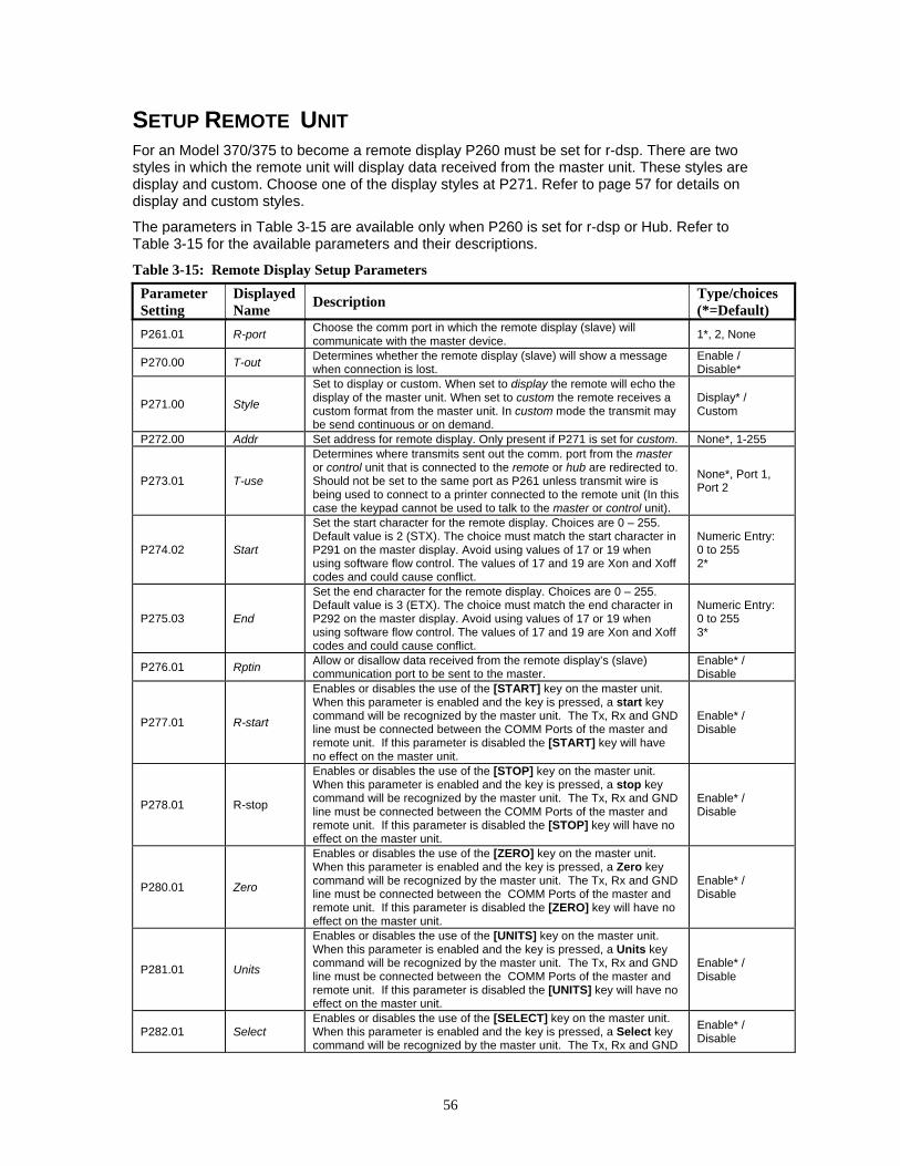
56
SETUP REMOTE UNIT For an Model 370/375 to become a remote display P260 must be set for r-dsp. There are two styles in which the remote unit will display data received from the master unit. These styles are display and custom. Choose one of the display styles at P271. Refer to page 57 for details on display and custom styles.
The parameters in Table 3-15 are available only when P260 is set for r-dsp or Hub. Refer to Table 3-15 for the available parameters and their descriptions.
Table 3-15: Remote Display Setup Parameters Parameter Setting
Displayed Name Description Type/choices
(*=Default) P261.01 R-port Choose the comm port in which the remote display (slave) will
communicate with the master device. 1*, 2, None
P270.00 T-out Determines whether the remote display (slave) will show a message when connection is lost.
Enable / Disable*
P271.00 Style
Set to display or custom. When set to display the remote will echo the display of the master unit. When set to custom the remote receives a custom format from the master unit. In custom mode the transmit may be send continuous or on demand.
Display* / Custom
P272.00 Addr Set address for remote display. Only present if P271 is set for custom. None*, 1-255
P273.01 T-use
Determines where transmits sent out the comm. port from the master or control unit that is connected to the remote or hub are redirected to. Should not be set to the same port as P261 unless transmit wire is being used to connect to a printer connected to the remote unit (In this case the keypad cannot be used to talk to the master or control unit).
None*, Port 1, Port 2
P274.02 Start
Set the start character for the remote display. Choices are 0 – 255. Default value is 2 (STX). The choice must match the start character in P291 on the master display. Avoid using values of 17 or 19 when using software flow control. The values of 17 and 19 are Xon and Xoff codes and could cause conflict.
Numeric Entry: 0 to 255 2*
P275.03 End
Set the end character for the remote display. Choices are 0 – 255. Default value is 3 (ETX). The choice must match the end character in P292 on the master display. Avoid using values of 17 or 19 when using software flow control. The values of 17 and 19 are Xon and Xoff codes and could cause conflict.
Numeric Entry: 0 to 255 3*
P276.01 Rptin Allow or disallow data received from the remote display’s (slave) communication port to be sent to the master.
Enable* / Disable
P277.01 R-start
Enables or disables the use of the [START] key on the master unit. When this parameter is enabled and the key is pressed, a start key command will be recognized by the master unit. The Tx, Rx and GND line must be connected between the COMM Ports of the master and remote unit. If this parameter is disabled the [START] key will have no effect on the master unit.
Enable* / Disable
P278.01 R-stop
Enables or disables the use of the [STOP] key on the master unit. When this parameter is enabled and the key is pressed, a stop key command will be recognized by the master unit. The Tx, Rx and GND line must be connected between the COMM Ports of the master and remote unit. If this parameter is disabled the [STOP] key will have no effect on the master unit.
Enable* / Disable
P280.01 Zero
Enables or disables the use of the [ZERO] key on the master unit. When this parameter is enabled and the key is pressed, a Zero key command will be recognized by the master unit. The Tx, Rx and GND line must be connected between the COMM Ports of the master and remote unit. If this parameter is disabled the [ZERO] key will have no effect on the master unit.
Enable* / Disable
P281.01 Units
Enables or disables the use of the [UNITS] key on the master unit. When this parameter is enabled and the key is pressed, a Units key command will be recognized by the master unit. The Tx, Rx and GND line must be connected between the COMM Ports of the master and remote unit. If this parameter is disabled the [UNITS] key will have no effect on the master unit.
Enable* / Disable
P282.01 Select Enables or disables the use of the [SELECT] key on the master unit. When this parameter is enabled and the key is pressed, a Select key command will be recognized by the master unit. The Tx, Rx and GND
Enable* / Disable
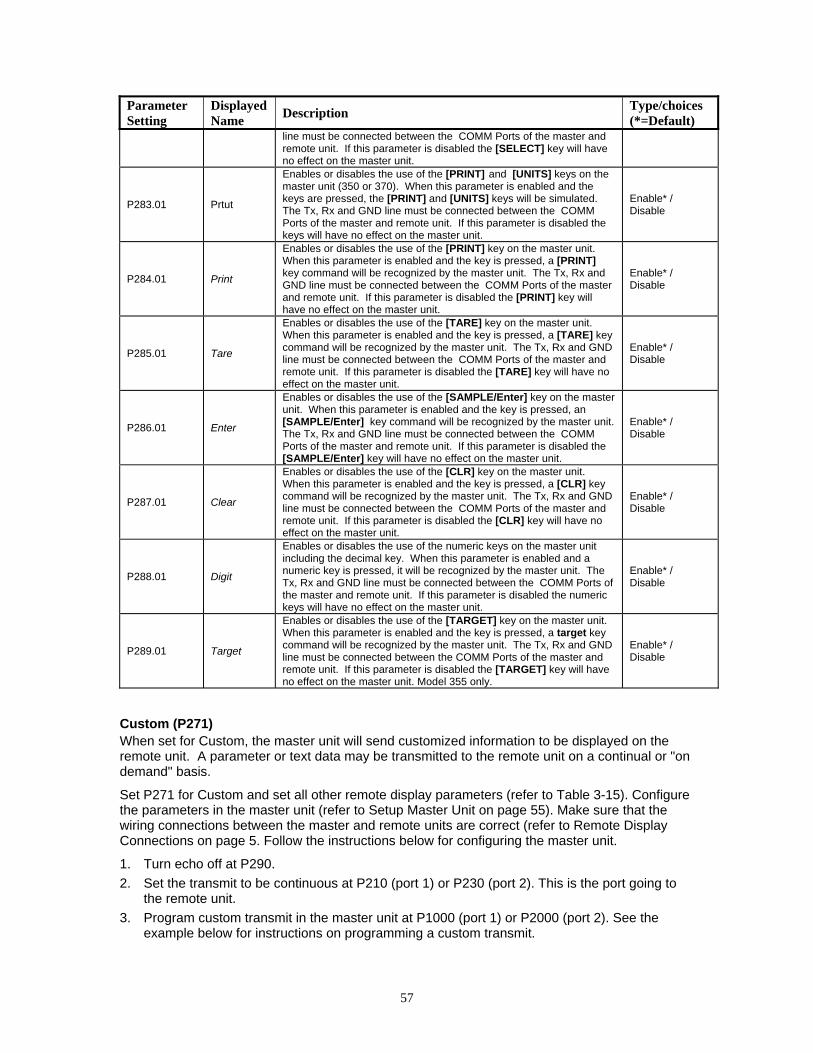
57
Parameter Setting
Displayed Name Description Type/choices
(*=Default) line must be connected between the COMM Ports of the master and remote unit. If this parameter is disabled the [SELECT] key will have no effect on the master unit.
P283.01 Prtut
Enables or disables the use of the [PRINT] and [UNITS] keys on the master unit (350 or 370). When this parameter is enabled and the keys are pressed, the [PRINT] and [UNITS] keys will be simulated. The Tx, Rx and GND line must be connected between the COMM Ports of the master and remote unit. If this parameter is disabled the keys will have no effect on the master unit.
Enable* / Disable
P284.01 Print
Enables or disables the use of the [PRINT] key on the master unit. When this parameter is enabled and the key is pressed, a [PRINT] key command will be recognized by the master unit. The Tx, Rx and GND line must be connected between the COMM Ports of the master and remote unit. If this parameter is disabled the [PRINT] key will have no effect on the master unit.
Enable* / Disable
P285.01 Tare
Enables or disables the use of the [TARE] key on the master unit. When this parameter is enabled and the key is pressed, a [TARE] key command will be recognized by the master unit. The Tx, Rx and GND line must be connected between the COMM Ports of the master and remote unit. If this parameter is disabled the [TARE] key will have no effect on the master unit.
Enable* / Disable
P286.01 Enter
Enables or disables the use of the [SAMPLE/Enter] key on the master unit. When this parameter is enabled and the key is pressed, an [SAMPLE/Enter] key command will be recognized by the master unit. The Tx, Rx and GND line must be connected between the COMM Ports of the master and remote unit. If this parameter is disabled the [SAMPLE/Enter] key will have no effect on the master unit.
Enable* / Disable
P287.01 Clear
Enables or disables the use of the [CLR] key on the master unit. When this parameter is enabled and the key is pressed, a [CLR] key command will be recognized by the master unit. The Tx, Rx and GND line must be connected between the COMM Ports of the master and remote unit. If this parameter is disabled the [CLR] key will have no effect on the master unit.
Enable* / Disable
P288.01 Digit
Enables or disables the use of the numeric keys on the master unit including the decimal key. When this parameter is enabled and a numeric key is pressed, it will be recognized by the master unit. The Tx, Rx and GND line must be connected between the COMM Ports of the master and remote unit. If this parameter is disabled the numeric keys will have no effect on the master unit.
Enable* / Disable
P289.01 Target
Enables or disables the use of the [TARGET] key on the master unit. When this parameter is enabled and the key is pressed, a target key command will be recognized by the master unit. The Tx, Rx and GND line must be connected between the COMM Ports of the master and remote unit. If this parameter is disabled the [TARGET] key will have no effect on the master unit. Model 355 only.
Enable* / Disable
Custom (P271) When set for Custom, the master unit will send customized information to be displayed on the remote unit. A parameter or text data may be transmitted to the remote unit on a continual or "on demand" basis.
Set P271 for Custom and set all other remote display parameters (refer to Table 3-15). Configure the parameters in the master unit (refer to Setup Master Unit on page 55). Make sure that the wiring connections between the master and remote units are correct (refer to Remote Display Connections on page 5. Follow the instructions below for configuring the master unit.
1. Turn echo off at P290. 2. Set the transmit to be continuous at P210 (port 1) or P230 (port 2). This is the port going to
the remote unit. 3. Program custom transmit in the master unit at P1000 (port 1) or P2000 (port 2). See the
example below for instructions on programming a custom transmit.

58
FYI If time out is enabled (P270), then the transmit should be set for continuous at P210 or P230 and have stability disabled at P212 or P232
Example: The master unit will be active and the Net weight will be displayed on the remote unit. The net and lb annunciators will illuminate. The codes for the annunciators will be entered as they are control codes (see Entering ASCII Control Codes on page 32). The address of the remote unit at P272 is 4. If P272 is set to None!, do not enter anything for the address field. Access custom transmit 1 (P1000) or custom transmit 2 (P2000).
Format String: If P274 and P275 = 1 - 255 <Start Character>, <Address>, <Annunciator 1>, <Annunciator 2>, <Parameter>, <End Character> ~or~ If P274 or P275 = 0 <Address>, <Annunciator 1>, <Annunciator 2>, <Parameter>, <Line Feed>
Custom Transmit : 1. .002 [SAMPLE/Enter] or [TARE] - <Start Character> 2. .004 [SAMPLE/Enter] or [TARE] - <Address> 3. .016 [SAMPLE/Enter] or [TARE] - <Annunciator 1> 4. .064 [SAMPLE/Enter] or [TARE] <Annunciator 2> 5. [SAMPLE/Enter] or [TARE], 1, [SAMPLE/Enter] or [TARE], 160, [SAMPLE/Enter] or
[TARE] - <Net Parameter> 6. .003 [SAMPLE/Enter] or [TARE] - <End Character> 7. Save changes and exit the setup mode.
Table 3-16: Annunciator Choices ASCII Code 128 64 32 16 8 4 2 0 Annunciator 1 Good2 Gross Net Qty Other kg Annunciator 2 lb Spt 1 Spt 2 Spt 3 0 Motion
The start character and end character can be any ASCII character 1 - 255. Refer to Table 3-16 for the annunciator codes to be entered in the custom transmit. Always use 160 for the format code when entering a parameter.
ACCESS THE SETUP MODE FROM THE REMOTE DISPLAY MODE If the Model 370/375 is set for remote display, unplug the unit and press [ZERO] + [SELECT] upon power up. Follow the instructions below to access the setup mode.

59
330000 SSeerriieess CCoommmmaanndd CCooddeess It is possible to send commands through the serial port to perform specific tasks.
Table 3-17: Single Keystrokes
Hex Decimal Symbol Percent equivalent
Master / Remote Action
0 0 NULL none M As part of an echo used to indicate character information starting at 1st of 10 characters
1 1 SOH none M As part of an echo used to indicate character information starting at 2nd of 10 characters
2 2 STX none M Used to begin an echo OR as part of an echo used to indicate character information starting at 3rd of 10 characters
3 3 ETX none M Normally to end an echo OR as part of an echo used to indicate character information starting at 4th of 10 characters
4 4 EOT none M As part of an echo used to indicate character information starting at 5th of 10 characters.
5 5 ENQ none M As part of an echo used to indicate character information starting at 6th of 10 characters.
6 6 ACK none M As part of an echo used to indicate character information starting at 7th of 10 characters.
7 7 BEL none M As part of an echo used to indicate character information starting at 8th of 10 characters.
8 8 BS none M Backspace OR as part of an echo used to indicate character information starting at 9th of 10 characters.
9 9 HT none M As part of an echo used to indicate character information starting at 10th of 10 characters.
A 10 LF none M As part of an echo used to indicate numeric display information.
D 13 CR or CTL-M none M
Clear Key (clears user input or can initiate an action). As part of an echo used to indicate annunciator & display toggle scheme information.
11 17 CTL-Q none M/R Xon 13 19 CTL-S none M/R Xoff 81 129 %[Ctrl-A] M Target Key 85 133 %[Ctrl-E] M Start Key 86 134 %[Ctrl-F] M Stop Key 95 149 %[Ctrl-U] M Echo display (all 3 lines) out comm. 1 96 150 %[Ctrl-V] M Echo display (all 3 lines) out comm. 2
B9 185 %9 M Enters the number before the %9 as the piece weight
D0 208 %P M Pause D0 208 %Q M Send out transmits one and two D2 210 %R M Remote Key 2 E0 224 %’ M Backward Select E3 227 %c M Clear Key (clears user input or can initiate an action E5 229 %e M Enter Key E9 233 %i M ID Key (Print & Units on 370) EF 239 %o M/R Turn off 370 F0 240 %p M Print Key/ Arrow Up Key F2 242 %r M Remote Key 1 F3 243 %s M Select Key F4 244 %t M Tare Key F5 245 %u M Units Key/ Right Arrow Key F6 246 %v M/R Enter Setup F8 248 %x M [Print][Select] Keys - Extended Resolution Gross FA 250 %z M Zero Key

60
Table 3-18: Multiple Keystrokes
Hex Decimal Symbol Percent equivalent
Master / Remote Action
[Z] [CR] %z M Zero Key (weigh mode only) [W] [CR] %p M Print Key (weigh mode only) [P] [CR] %p M Print Key (weigh mode only)
IIDD NNuummbbeerr EEnnttrryy It is possible to enter an ID number and have it print out on a ticket.
• P210 or P230 must be set to ID. • P213 or P233 must be set to cust. • P1000 or P2000 must contain Parameter 21. Use a format of 128 to remove the name id
from the transmit. Enter an ID from the weigh mode:
1. Press the [PRINT] key from the weigh mode. The display will show the current ID number if one has been entered previously.
2. Key in the desire ID number (numeric and/or alphanumeric) and press [TARE] (Model 370) or [SAMPLE/Enter] (Model 375). This will print a ticket.
~or~ If the ID number shown is acceptable simply press [TARE] (Model 370) or [SAMPLE/Enter] (Model 375). This will print a ticket.
61
Chapter 4: CALIBRATION
SSeettuupp MMooddee CCaalliibbrraattiioonn You can enter the Calibration Mode after accessing the Setup Mode to view and/or change parameter settings (see Setup Mode on page 15).
To access the Calibration Mode when viewing any setup parameter: 1. From the Setup Mode, press [ZERO].
DISPLAY READS Enter ~ =Cal! 2. Press [TARE] or [SAMPLE/Enter].
DISPLAY READS First ~ Zero? ~ -0.26
FAST CALIBRATION Fast Calibration allows calibration of the Model 370/375 scale system without accessing the Setup Mode.
To access Fast Calibration from the Weigh Mode (370): 1. From the Weigh Mode, press [ZERO] + [SELECT].
DISPLAY READS Setup~Enter ~ Code! 2. Press [ZERO] [PRINT] [UNITS] [TARE].
DISPLAY READS Fast ~ Cal!~First ~ Zero? ~ -0.26 To access Fast Calibration from the Weigh Mode (375):
1. From the Weigh Mode key in 100 [SELECT]. DISPLAY READS Setup~Enter ~ Code!
2. Key in 54321 [SAMPLE/Enter]. DISPLAY READS Fast ~ Cal!~First ~ Zero? ~ -0.26
Fast Calibration can also be accessed if the following data stream is received via the comm port:
100%s54321%e
PERFORMING CALIBRATION Calibration always begins by establishing a zero (no-load) reference. A complete calibration also requires establishing a span (test load) reference. This section details various methods for obtaining zero and span references.
Establishing Zero The Model 370/375 provides five methods for obtaining a zero (no load) calibration reference, First Zero, Last Zero, False Zero, Only Zero, and Cal Reset.
Press [ZERO] or [CLR] during calibration to back up one step in the procedure.

62
To select a calibration method (370):
1. Press [ZERO] + [SELECT] to display the calibration prompt. 2. Press [ZERO] [PRINT] [UNITS] [TARE] to access the Calibration Mode. 3. Press [SELECT] to scroll through the five selections. 4. Press [TARE] to establish zero.
To select a calibration method (375):
1. Press 100 [SELECT] to display the calibration prompt. 2. Press 54321 [SAMPLE/Enter] to access the Calibration Mode. 3. Press [SELECT] to scroll through the five selections. 4. Press [SAMPLE/Enter] to establish zero.
FIRST ZERO The most common zeroing procedure, First Zero is used to establish a new zero (no load) calibration reference before proceeding to span the Model 370/375. Use this method for first-time calibration and complete recalibration.
First Zero Calibration Method Example (370):
1. From the Weigh Mode, press [ZERO] + [SELECT]. DISPLAY READS Setup
2. Press [ZERO] [PRINT] [UNITS] [TARE]. DISPLAY READS Fast ~ Cal~First ~ Zero? ~ -0.26
3. Remove any load on the scale. DISPLAY READS First ~ Zero? ~ -0.42
4. Press [TARE] to establish zero. DISPLAY READS 0.00
5. Pause for motion delay. DISPLAY READS Enter ~ Load ~ 0.00
6. Place a 100lb test weight on scale. DISPLAY READS Enter ~ Load ~ 99.66
7. Enter 100. DISPLAY READS 100
8. Press [TARE] to establish span. DISPLAY READS 100.00
9. Pause for motion delay. DISPLAY READS Cal ~ Good? ~ 100.00
10. Press [TARE] to accept calibration. DISPLAY READS Enter ~ =Stor
11. Press [TARE] to save calibration. DISPLAY READS Enter ~ =End
12. Press [TARE] to exit calibration. DISPLAY READS 100.00
13. Remove the calibration weight. DISPLAY READS 0.00
First Zero Calibration Method Example (375):
1. From the Weigh Mode key in 100 [SELECT].
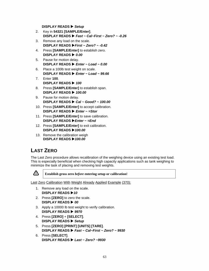
63
DISPLAY READS Setup 2. Key in 54321 [SAMPLE/Enter]. DISPLAY READS Fast ~ Cal~First ~ Zero? ~ -0.26 3. Remove any load on the scale. DISPLAY READS First ~ Zero? ~ -0.42 4. Press [SAMPLE/Enter] to establish zero. DISPLAY READS 0.00 5. Pause for motion delay. DISPLAY READS Enter ~ Load ~ 0.00 6. Place a 100lb test weight on scale. DISPLAY READS Enter ~ Load ~ 99.66 7. Enter 100. DISPLAY READS 100 8. Press [SAMPLE/Enter] to establish span. DISPLAY READS 100.00 9. Pause for motion delay. DISPLAY READS Cal ~ Good? ~ 100.00 10. Press [SAMPLE/Enter] to accept calibration. DISPLAY READS Enter ~ =Stor 11. Press [SAMPLE/Enter] to save calibration. DISPLAY READS Enter ~ =End 12. Press [SAMPLE/Enter] to exit calibration. DISPLAY READS 100.00 13. Remove the calibration weigh
DISPLAY READS 100.00
LAST ZERO The Last Zero procedure allows recalibration of the weighing device using an existing test load. This is especially beneficial when checking high capacity applications such as tank weighing to minimize the task of placing and removing test weights.
Establish gross zero before entering setup or calibration!
Last Zero Calibration With Weight Already Applied Example (370):
1. Remove any load on the scale. DISPLAY READS 10
2. Press [ZERO] to zero the scale. DISPLAY READS 00
3. Apply a 10000 lb test weight to verify calibration. DISPLAY READS 9970
4. Press [ZERO] + [SELECT]. DISPLAY READS Setup
5. Press [ZERO] [PRINT] [UNITS] [TARE]. DISPLAY READS Fast ~ Cal~First ~ Zero? ~ 9930
6. Press [SELECT]. DISPLAY READS Last ~ Zero? ~9930

64
7. Press [TARE] to use last zero. DISPLAY READS Enter ~ Load? ~ 9970
8. Enter 10000. DISPLAY READS 10000
9. Press [TARE] to establish span. DISPLAY READS 10000.
10. Pause for motion delay. DISPLAY READS Cal ~ Good? ~ 10000.
11. Press [TARE] to accept calibration. DISPLAY READS Enter ~ =Stor
12. Press [TARE] to save calibration. DISPLAY READS Enter ~ =End
13. Press [TARE] to exit calibration. DISPLAY READS 10000.
14. Remove the calibration weight. DISPLAY READS 0.
Last Zero Calibration With Weight Already Applied Example (375):
1. Remove any load on the scale. DISPLAY READS 10.
2. Press [ZERO] to zero the scale. DISPLAY READS 00.
3. Apply a 10000 lb test weight to verify calibration. DISPLAY READS 9970.
4. Press 100 [SELECT]. DISPLAY READS Setup
5. Press 54321 [SAMPLE/Enter]. DISPLAY READS Fast ~ Cal~First ~ Zero? ~ 9930.
6. Press [SELECT]. DISPLAY READS Last ~ Zero? ~9930.
7. Press [SAMPLE/Enter] to use last zero. DISPLAY READS Enter ~ Load? ~ 9970.
8. Enter 10000. DISPLAY READS 10000
9. Press [SAMPLE/Enter] to establish span. DISPLAY READS 10000.
10. Pause for motion delay. DISPLAY READS Cal ~ Good? ~ 10000.
11. Press [SAMPLE/Enter] to accept calibration. DISPLAY READS Enter ~ =Stor
12. Press [SAMPLE/Enter] to save calibration. DISPLAY READS Enter ~ =End
13. Press [SAMPLE/Enter] to exit calibration. DISPLAY READS 10000.
14. Remove the calibration weight. DISPLAY READS 00.

65
FALSE ZERO False Zero calibrates the Model 370/375 without removing the current gross weight. This is particularly useful in tank weighing applications where it may be both time consuming and costly to completely empty the tank. This operation is achieved by establishing a false (temporary zero) zero reference. Test weights may then be added to verify calibration. The zero reference determined during the last calibration is not affected.
False Zero Calibration Without Removing Existing Load Example (370):
1. Press [ZERO] + [SELECT]. DISPLAY READS Setup
2. Press [ZERO] [PRINT] [UNITS] [TARE]. DISPLAY READS Fast ~ Cal~First ~ Zero? ~ 5075.
3. Press [SELECT] [SELECT]. DISPLAY READS False ~ Zero? ~5075.
4. Press [TARE] to establish false (temporary) zero. DISPLAY READS Units ~ =lb
5. Pause to display calibration units. DISPLAY READS Enter ~ Load? ~ 00.
6. Place a 2500lb test weight on scale. DISPLAY READS Enter ~ Load? ~ 2510.
7. Enter 2500. DISPLAY READS 2500
8. Press [TARE] to establish span. DISPLAY READS 2500.
9. Pause for motion delay. DISPLAY READS Cal ~ Good? ~ 2500.
10. Press [TARE] to accept calibration. DISPLAY READS Enter ~ =Stor
11. Press [TARE] to save calibration. DISPLAY READS Enter ~ =End
12. Press [TARE] to exit calibration. DISPLAY READS 5055.
13. Remove the calibration weight. DISPLAY READS 00.
False Zero Calibration Without Removing Existing Load Example (375):
1. Press 100 [SELECT]. DISPLAY READS Setup
2. Press 54321 [SAMPLE/Enter]. DISPLAY READS Fast ~ Cal~First ~ Zero? ~ 5075.
3. Press [SELECT] [SELECT]. DISPLAY READS False ~ Zero? ~5075.
4. Press [SAMPLE/Enter] to establish false (temporary) zero. DISPLAY READS Units ~ =lb
5. Pause to display calibration units. DISPLAY READS Enter ~ Load? ~ 00.
6. Place a 2500lb test weight on scale. DISPLAY READS Enter ~ Load? ~ 2510.

66
7. Enter 2500. DISPLAY READS 2500
8. Press [SAMPLE/Enter] to establish span. DISPLAY READS 2500.
9. Pause for motion delay. DISPLAY READS Cal ~ Good? ~ 2500.
10. Press [SAMPLE/Enter] to accept calibration. DISPLAY READS Enter ~ =Stor
11. Press [SAMPLE/Enter] to save calibration. DISPLAY READS Enter ~ =End
12. Press [SAMPLE/Enter] to exit calibration. DISPLAY READS 5055.
13. Remove the calibration weight. DISPLAY READS 00.
ONLY ZERO Only Zero is used to establish a new calibration zero without affecting the span. This is useful for correcting changes to the scale's dead load, for example adding safety rails to a truck scale platform.
Only Zero Calibration Example (370):
1. From the Weigh Mode, press [ZERO] + [SELECT]. DISPLAY READS Setup
2. Press [ZERO] [PRINT] [UNITS] [TARE]. DISPLAY READS Fast ~ Cal~First ~ Zero? ~2640.
3. Press [SELECT] [SELECT] [SELECT]. DISPLAY READS Only ~ Zero? ~ 2640.
4. Remove any load on the scale. DISPLAY READS Only ~ Zero? ~ 2620.
5. Press [TARE] to establish zero. DISPLAY READS 00.
6. Pause for motion delay. DISPLAY READS Cal ~ Good? ~ 00.
7. Press [TARE] to accept calibration. DISPLAY READS Enter ~ =Stor
8. Press [TARE] to save calibration. DISPLAY READS Enter ~ =End
9. Press [TARE] to exit calibration. DISPLAY READS 00.
Only Zero Calibration Example (375):
1. From the Weigh Mode, press 100 [SELECT]. DISPLAY READS Setup
2. Press 54321 [SAMPLE/Enter]. DISPLAY READS Fast ~ Cal~First ~ Zero? ~2640.
3. Press [SELECT] [SELECT] [SELECT].

67
DISPLAY READS Only ~ Zero? ~ 2640. 4. Remove any load on the scale.
DISPLAY READS Only ~ Zero? ~ 2620. 5. Press [SAMPLE/Enter] to establish zero.
DISPLAY READS 00. 6. Pause for motion delay.
DISPLAY READS Cal ~ Good? ~ 00. 7. Press [SAMPLE/Enter] to accept calibration.
DISPLAY READS Enter ~ =Stor
8. Press [SAMPLE/Enter] to save calibration. DISPLAY READS Enter ~ =End
9. Press [SAMPLE/Enter] to exit calibration. DISPLAY READS 00.
RESET CALIBRATION Cal Reset may be necessary when an over-load or under-load condition exists, preventing the completion of the calibration process. Calibration Reset adjusts the zero and gain factors of the A/D amplifier to factory default values for maximum sensitivity.
After performing a calibration reset, a complete recalibration is required. The effects of a calibration reset do not take effect until the Model 370/375 recalibrated and calibration information has been saved.
If Code 02 (under-load) or Code 03 (over-load) is displayed during calibration, press [CLR] to perform a calibration reset.
Reset Calibration Gain Factors Example (370):
1. From the Weigh Mode, press [ZERO] + [SELECT]. DISPLAY READS Setup
2. Press [ZERO] [PRINT] [UNITS] [TARE]. DISPLAY READS Fast ~ Cal~First ~ Zero? ~2640.
3. Remove any load on the scale. DISPLAY READS First ~ Zero? ~ xx.xx
4. Press [TARE] to establish zero. DISPLAY READS Enter ~ Load? ~ 0.00
5. Place a 100lb test weight on scale. DISPLAY READS Code03
6. Press [ZERO]. DISPLAY READS First ~ Zero? ~ -0.26
7. Remove any load on the scale. DISPLAY READS First ~ Zero? ~ -0.42
8. Press [TARE] to establish zero. DISPLAY READS 0.00
9. Pause for motion delay. DISPLAY READS Enter ~ Load ~ 0.00
10. Place a 100lb test weight on scale.
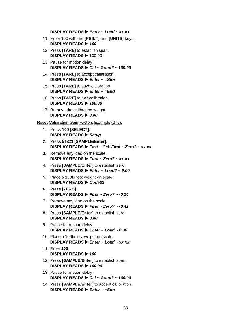
68
DISPLAY READS Enter ~ Load ~ xx.xx 11. Enter 100 with the [PRINT] and [UNITS] keys.
DISPLAY READS 100 12. Press [TARE] to establish span.
DISPLAY READS 100.00 13. Pause for motion delay.
DISPLAY READS Cal ~ Good? ~ 100.00 14. Press [TARE] to accept calibration.
DISPLAY READS Enter ~ =Stor 15. Press [TARE] to save calibration.
DISPLAY READS Enter ~ =End 16. Press [TARE] to exit calibration.
DISPLAY READS 100.00 17. Remove the calibration weight.
DISPLAY READS 0.00
Reset Calibration Gain Factors Example (375):
1. Press 100 [SELECT]. DISPLAY READS Setup
2. Press 54321 [SAMPLE/Enter]. DISPLAY READS Fast ~ Cal~First ~ Zero? ~ xx.xx
3. Remove any load on the scale. DISPLAY READS First ~ Zero? ~ xx.xx
4. Press [SAMPLE/Enter] to establish zero. DISPLAY READS Enter ~ Load? ~ 0.00
5. Place a 100lb test weight on scale. DISPLAY READS Code03
6. Press [ZERO]. DISPLAY READS First ~ Zero? ~ -0.26
7. Remove any load on the scale. DISPLAY READS First ~ Zero? ~ -0.42
8. Press [SAMPLE/Enter] to establish zero. DISPLAY READS 0.00
9. Pause for motion delay. DISPLAY READS Enter ~ Load ~ 0.00
10. Place a 100lb test weight on scale. DISPLAY READS Enter ~ Load ~ xx.xx
11. Enter 100. DISPLAY READS 100
12. Press [SAMPLE/Enter] to establish span. DISPLAY READS 100.00
13. Pause for motion delay. DISPLAY READS Cal ~ Good? ~ 100.00
14. Press [SAMPLE/Enter] to accept calibration. DISPLAY READS Enter ~ =Stor

69
15. Press [SAMPLE/Enter] to save calibration. DISPLAY READS Enter ~ =End
16. Press [SAMPLE/Enter] to exit calibration. DISPLAY READS 100.00
17. Remove the calibration weight. DISPLAY READS 0.00
MMuullttii--PPooiinntt LLiinneerriizzaattiioonn If the load cell signal input to the Model 370/375 has good repeatability and stability, then using multi-point linearization during calibration may significantly improve the ultimate accuracy of the data displayed by the Model 370/375. Parameter 119 (P119) enables or disables this feature. Initially, the same basic procedures as a normal calibration are used to perform a multi-point linearization. All of the prompts provided will be exactly the same as a standard calibration for each cal point up to the Cal ~ Good? prompt. If items are consistently being weighed on either the high or low end of the cell capacity, the points of calibration can be skewed to either end of the spectrum. Multi-point linearization can compensate for a cell that is non-linear. Refer to page 61 for the instructions on how to enter the calibration mode.
First Zero? 1. Remove all weight and press [TARE] or [SAMPLE/Enter]. 2. From the Enter Load prompt key in the first calibration point and press [TARE] or
[SAMPLE/Enter]. 3. From the Add Load prompt add the weight of the first calibration point and press [TARE]
or [SAMPLE/Enter]. 4. For calibration points 2 -5; Simply add the weight which you want to use for the next
calibration point, then key in the value of the applied weight and press [TARE] or [SAMPLE/Enter]. You may wish to add weight until the displayed weight differs from the actual applied weight and then perform the next calibration at that point.
Reset Cal 1. Press [TARE] or [SAMPLE/Enter]. 2. From the First Zero? prompt remove all weight and press [TARE] or [SAMPLE/Enter]. 3. From the Enter Load prompt key in the first calibration point and press [TARE] or
[SAMPLE/Enter]. 4. From the Add Load prompt add the weight of the first calibration point and press [TARE]
or [SAMPLE/Enter]. 5. For calibration points 2 -5; Simply add the weight which you want to use for the next
calibration point, then key in the total applied weight and press [TARE] or [SAMPLE/Enter]. You may wish to add weight until the displayed weight differs from the actual applied weight and then perform the next calibration at that point.
Up to five calibration points may be established using this procedure. However if fewer calibration points are required, simply press [TARE] or [SAMPLE/Enter] without entering a value at the PntX prompt. Refer to Figure 4-1 for graph examples of 5-point calibration.
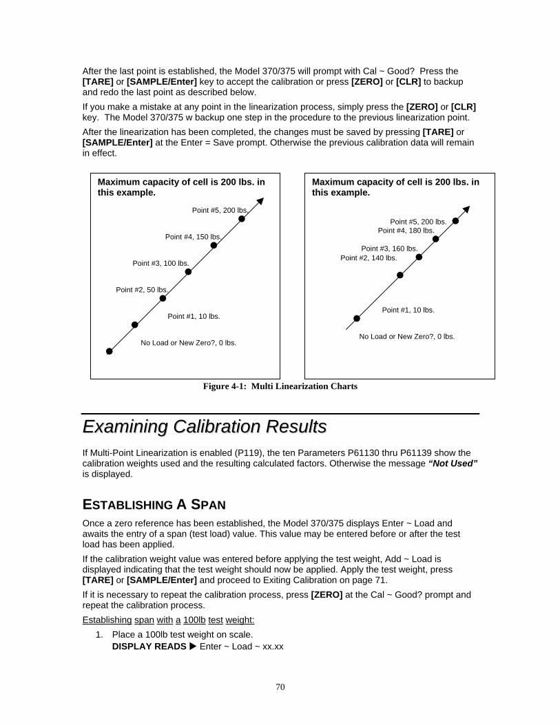
70
After the last point is established, the Model 370/375 will prompt with Cal ~ Good? Press the [TARE] or [SAMPLE/Enter] key to accept the calibration or press [ZERO] or [CLR] to backup and redo the last point as described below. If you make a mistake at any point in the linearization process, simply press the [ZERO] or [CLR] key. The Model 370/375 w backup one step in the procedure to the previous linearization point. After the linearization has been completed, the changes must be saved by pressing [TARE] or [SAMPLE/Enter] at the Enter = Save prompt. Otherwise the previous calibration data will remain in effect.
Figure 4-1: Multi Linearization Charts
EExxaammiinniinngg CCaalliibbrraattiioonn RReessuullttss If Multi-Point Linearization is enabled (P119), the ten Parameters P61130 thru P61139 show the calibration weights used and the resulting calculated factors. Otherwise the message “Not Used” is displayed.
ESTABLISHING A SPAN Once a zero reference has been established, the Model 370/375 displays Enter ~ Load and awaits the entry of a span (test load) value. This value may be entered before or after the test load has been applied. If the calibration weight value was entered before applying the test weight, Add ~ Load is displayed indicating that the test weight should now be applied. Apply the test weight, press [TARE] or [SAMPLE/Enter] and proceed to Exiting Calibration on page 71. If it is necessary to repeat the calibration process, press [ZERO] at the Cal ~ Good? prompt and repeat the calibration process. Establishing span with a 100lb test weight:
1. Place a 100lb test weight on scale. DISPLAY READS Enter ~ Load ~ xx.xx
Maximum capacity of cell is 200 lbs. in this example. Point #5, 200 lbs. Point #4, 150 lbs. Point #3, 100 lbs. Point #2, 50 lbs. Point #1, 10 lbs. No Load or New Zero?, 0 lbs.
Maximum capacity of cell is 200 lbs. in this example. Point #5, 200 lbs. Point #4, 180 lbs. Point #3, 160 lbs. Point #2, 140 lbs. Point #1, 10 lbs. No Load or New Zero?, 0 lbs.
71
2. Enter 100. DISPLAY READS 100
3. Press [ZERO] or [SAMPLE/Enter] to establish span. DISPLAY READS 100.00
4. Pause for motion delay. DISPLAY READS Cal ~ Good? ~ 100.00
When making a significant change to the previous calibration, or when the calibration weight is less than 5% of full scale capacity, ReCal ~ ??? will be displayed instead of Cal ~ Good? In this event it is recommended that the calibration be performed a second time. Press [TARE] or [SAMPLE/Enter] to recalibrate, or press [ZERO] to skip recalibration.
EExxiittiinngg CCaalliibbrraattiioonn Once zero and span have been established, the newly acquired calibration information must be saved to non-volatile memory before it will be realized in the Weigh Mode. To exit and save calibration information:
1. Press [TARE] or [SAMPLE/Enter] to accept calibration. DISPLAY READS Enter ~ =Stor
2. Press [TARE] or [SAMPLE/Enter] to save calibration. DISPLAY READS Enter ~ =End
3. Press [TARE] or [SAMPLE/Enter] to exit calibration. DISPLAY READS 100.00
To exit without saving calibration information: 1. Press [TARE] or [SAMPLE/Enter] to accept calibration.
DISPLAY READS Enter ~ =Stor 2. Press [CLR].
DISPLAY READS Enter ~ =Undo 3. Press [TARE] or [SAMPLE/Enter].
DISPLAY READS Enter ~ =End 4. Press [TARE] or [SAMPLE/Enter] to exit calibration.
DISPLAY READS 99.66
AAnnaalloogg OOuuttppuutt CCaalliibbrraattiioonn The analog output calibration procedure establishes explicit zero and full scale values for each of the three analog output modes: 0 - 10V, 0 - 20 mA and 4- 20 mA. There are five adjustment values for the analog option, located at the information parameters P61200 through P61205 that allow the zero and full scale output of each mode to be adjusted to exact values. This allows the analog option to be configured to match the needs of the system being connected to its outputs.
The calibration values for each of these modes have been determined at the factory. These values are provided on paper with each board to make calibrating the analog option a simple
When saving calibration, parameters changed in the Setup Mode are also saved with their new selections.

72
process. Each analog option board can be identified by its serial number, which is entered in the unit during the calibration process.
Table 4-1: Analog Output Calibration Parameters Parameter Setting
Displayed Name
Description Type/choices (*=Default)
P61200
10oFF Value required to precisely output 0V in 0 –
10V output mode (i.e. offset).
Numeric Entry: 0 to 15,000 2,923*
P61201
10Gn Value required to precisely output 10V in 0 –
10V output mode (i.e. gain).
Numeric Entry: 50,000 to 65,535 61,027*
P61202 0oFF Value required to precisely output 0 mA in 0 –
20 mA output mode (i.e. offset). Not adjustable: 0*
P61203
0Gn Value required to precisely output 20 mA in 0 –
20mA output mode (i.e. gain).
Numeric Entry: 50,000 to 65,535 54,555*
P61204
4oFF Value required to precisely output 0 mA in 4 –
20 mA output mode (i.e. offset).
Numeric Entry: 0 to 15,000 10,910*
P61205
4Gn Value required to precisely output 20 mA in 4 –
20mA output mode (i.e. gain).
Numeric Entry: 50,000 to 65,535 54,555*
P61206 Srln Analog option board serial number. Numeric Entry:
0* - 4,294,967,295
Entering Calibration Values Analog calibration values can be entered into the Model 370 and Model 375 by keying in the data in the left-hand column, beginning at the line starting with "61200…", replacing the "%s" character pairs with the [SELECT] key and "%e" with the [TARE] (370) or [SAMPLE] (375) key. The line with the "%c" is not adjustable and cannot be entered.
You can adjust the included factory recommended offset and gain values to precisely configure the system being connected to these outputs. Once the initial factory values have been entered, pressing the [TARE] (370) or [SAMPLE] (375) key will cause the count value to increase one count, and pressing the [PRINT] + [UNITS] keys will decrement the count value by one count. All changes made are updated "live" to aid in calibrating a specific device to the analog option board output. Holding down the key(s) will repeat the increment/decrement action.
Printout Example 100%s23640%e Access Setup Modes, Allowing Changes 60100%s%e P60100. c2004-GSE- 60101%s%e P60101. 0Model 370 370p27132 60102%s%e P60102. 09-02-2005 60200%s%e P60200. BrdSn 420679 60201%s%e P60201. AuditTrail Euro 00001 60202%s%e P60202. InsSn102245 60203%s%e P60203. AuditTrail Cal. 00025 60204%s%e P60204. AuditTrail Setup 00050 61200%s2923%e P61200. 10off 2923 61201%s61027%e P61201. 10 Gn 61027 61202%s0%c P61202. 0 off 0 61203%s54555%e P61203. 0 Gn 54555 61204%s10910%e P61204. 4 off 10910 61205%s54555%e P61205. 4 Gn 54555 61206%s123456%e P61206. Srl n 123456
%z Exit Setup Mode

73
Chapter 5: TROUBLESHOOTING This chapter contains error messages and information parameters, as well as information on setup parameter selections and A/D Calibration.
EErrrroorr MMeessssaaggeess The Model 370/375 utilizes the following types of error messages: Operational Errors, Setup Mode Errors, Hardware Errors, Calibration Errors, Communication Errors, and Miscellaneous Errors.
OPERATIONAL ERRORSCode02Under Load. Input signal is less than negative full scale. Check load cell wiring. Verify
correct capacity selection at P110.
Code03 Over Load. Input signal is greater than positive full scale. Use same checks as "under load" above.
Funct ~ Disbl Attempted to perform a function disabled in the Setup Mode.
Code 04 The digits on the display have exceed the six digit display capacity.
Code 05 Zero attempted beyond that allowed by P118.
Code 08 Input signal greatly exceeds the valid range. Check the load cell connection.
Tare ~ Error Negative tare attempted when disabled (P440 enabled).
Tare ~ GT FS Tare value greater than full scale capacity.
Delay Indicates that a motion delay is in effect (zero, tare, etc.).
Delay ~ Abort Acknowledges that a motion delayed function was aborted.
Print ~ Abort Acknowledges that a motion delayed print request was aborted.
Add ~ Load! If displayed after performing a count sample, this message indicates that a larger sample size is required.
Out of ~ Range Attempted to enter a value beyond the allowable range.
SPtxx ~ Error A conflict occurred with a setpoint value entry (example: target entry is less than preact). The digits 'xx' represent the last two digits of the setpoint parameter in error (example: SPt 5 ~ Error indicates a conflict at P5105, preact 1).
Need APS A setpoint start is initiated and the setpoint is based on quantity and no piece weight has been established (start will not occur).

74
SETUP MODE ERRORS Bad ~ Code! An incorrect access code was entered
Unit ~ Seald Access to the Setup or Calibration Mode was denied. Check the internal "YES/NO" program jumper.
Unit3 Ntep Code 49.
Parameter 440 (NTEP) is enabled and parameter 152 (third unit) is set to an additional unit. The third unit is not NTEP approved.
Entry ~ Error An invalid entry was made.
Need ~ Entry A numeric value was required before pressing [TARE] or [SAMPLE/Enter].
Out of ~Range The entered value exceeded the allowable range.
Can't ~ Set! Attempt to change a parameter that does not allow an entry.
ResGT ~ 260E3 Code 35.
The number of divisions exceeds 260000 (see P110, P111).
ResGT ~ 25E3 The number of divisions exceeds 25000 (see P110, P111).
ResLT ~ 100! The number of divisions is less than 100 (see P110, P111).
ResLT ~ 1 !! Number of divisions is less than one (see P110, P111).
SPtxx ~ Error A conflict occurred with a setpoint value entry (example: target entry is less than preact). The digits 'xx' represent the last two digits of the setpoint parameter in error (example: SPt 5 ~ Error indicates a conflict P5105, preact 1).
Prtcl ~ Error Existing protocol is invalid. The following are not allowed: P201 = 7 data bits, P202 = no parity, P203 = 1 stop bit
HARDWARE ERRORS Code00 An EPROM problem detected during power up (U2).
A-D ~ Bad! Or Code17
Problem with A/D chip detected. Disconnect any options installed and re-power the unit. Options are connected to the same serial lines as the A/D so they may prevent it from working properly.
Deflt ~ A-D
Bad A/D calibration values. Recalibrate A/D (see A/D Calibration Procedure on page 77.
Re- ~ Boot! EEPROM data could not be read. Attempting power-up reset.
Chec ~ E2 EEPROM data error (U4).
Deflt ~ Setup An error occurred when reading setup data from the EEPROM during power-up. All parameters are set to factory default.
Ch.XXXX A checksum error occurred during power-up. All anunciators are lit. The EPROM integrity test failed or is improperly seated.
NoSpc ~ Free! The current setup exceeds the setup RAM capacity.
E2 ~ Full! The EEPROM setup exceeds the memory capacity.
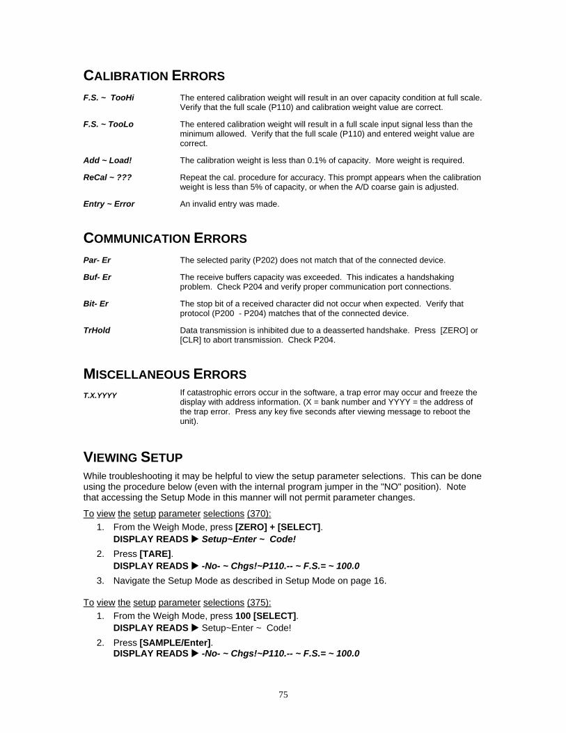
75
CALIBRATION ERRORS F.S. ~ TooHi The entered calibration weight will result in an over capacity condition at full scale.
Verify that the full scale (P110) and calibration weight value are correct.
F.S. ~ TooLo
The entered calibration weight will result in a full scale input signal less than the minimum allowed. Verify that the full scale (P110) and entered weight value are correct.
Add ~ Load! The calibration weight is less than 0.1% of capacity. More weight is required.
ReCal ~ ??? Repeat the cal. procedure for accuracy. This prompt appears when the calibration weight is less than 5% of capacity, or when the A/D coarse gain is adjusted.
Entry ~ Error An invalid entry was made.
COMMUNICATION ERRORS Par- Er The selected parity (P202) does not match that of the connected device.
Buf- Er The receive buffers capacity was exceeded. This indicates a handshaking problem. Check P204 and verify proper communication port connections.
Bit- Er The stop bit of a received character did not occur when expected. Verify that protocol (P200 - P204) matches that of the connected device.
TrHold Data transmission is inhibited due to a deasserted handshake. Press [ZERO] or [CLR] to abort transmission. Check P204.
MISCELLANEOUS ERRORS T.X.YYYY
If catastrophic errors occur in the software, a trap error may occur and freeze the display with address information. (X = bank number and YYYY = the address of the trap error. Press any key five seconds after viewing message to reboot the unit).
VIEWING SETUP While troubleshooting it may be helpful to view the setup parameter selections. This can be done using the procedure below (even with the internal program jumper in the "NO" position). Note that accessing the Setup Mode in this manner will not permit parameter changes.
To view the setup parameter selections (370): 1. From the Weigh Mode, press [ZERO] + [SELECT].
DISPLAY READS Setup~Enter ~ Code! 2. Press [TARE].
DISPLAY READS -No- ~ Chgs!~P110.-- ~ F.S.= ~ 100.0 3. Navigate the Setup Mode as described in Setup Mode on page 16.
To view the setup parameter selections (375): 1. From the Weigh Mode, press 100 [SELECT].
DISPLAY READS Setup~Enter ~ Code! 2. Press [SAMPLE/Enter].
DISPLAY READS -No- ~ Chgs!~P110.-- ~ F.S.= ~ 100.0
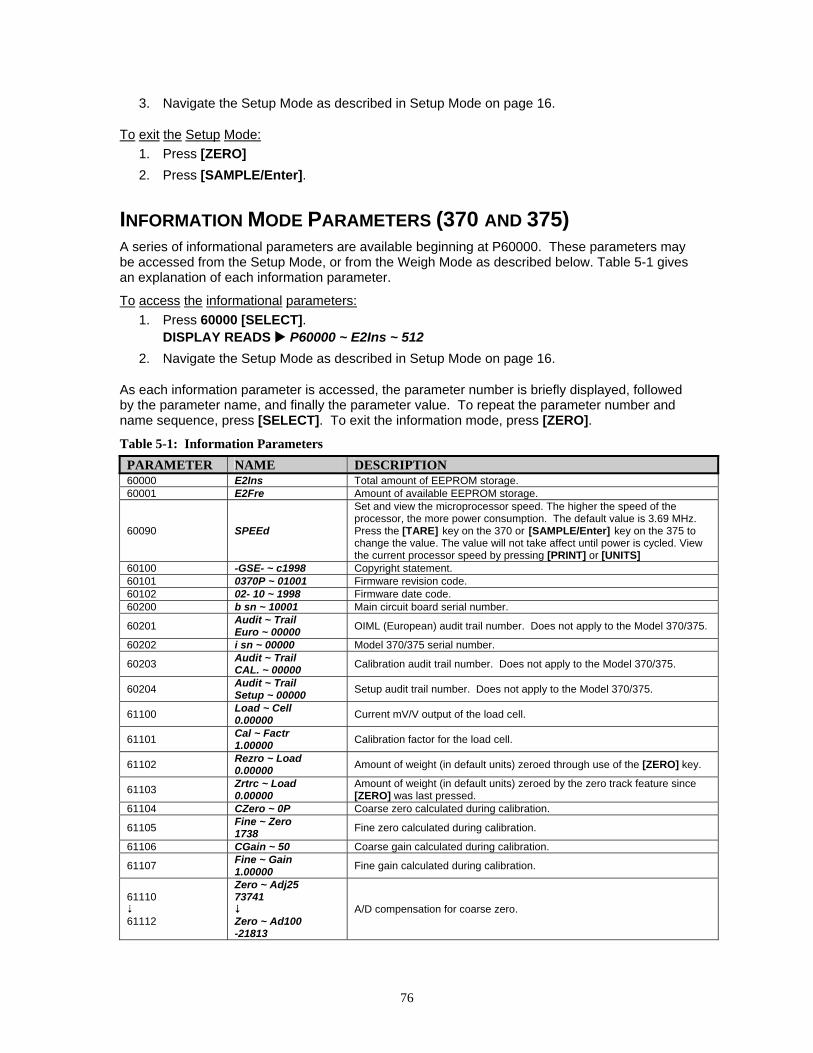
76
3. Navigate the Setup Mode as described in Setup Mode on page 16.
To exit the Setup Mode: 1. Press [ZERO] 2. Press [SAMPLE/Enter].
INFORMATION MODE PARAMETERS (370 AND 375) A series of informational parameters are available beginning at P60000. These parameters may be accessed from the Setup Mode, or from the Weigh Mode as described below. Table 5-1 gives an explanation of each information parameter.
To access the informational parameters: 1. Press 60000 [SELECT].
DISPLAY READS P60000 ~ E2Ins ~ 512 2. Navigate the Setup Mode as described in Setup Mode on page 16.
As each information parameter is accessed, the parameter number is briefly displayed, followed by the parameter name, and finally the parameter value. To repeat the parameter number and name sequence, press [SELECT]. To exit the information mode, press [ZERO].
Table 5-1: Information Parameters PARAMETER NAME DESCRIPTION 60000 E2Ins Total amount of EEPROM storage. 60001 E2Fre Amount of available EEPROM storage.
60090 SPEEd
Set and view the microprocessor speed. The higher the speed of the processor, the more power consumption. The default value is 3.69 MHz. Press the [TARE] key on the 370 or [SAMPLE/Enter] key on the 375 to change the value. The value will not take affect until power is cycled. View the current processor speed by pressing [PRINT] or [UNITS]
60100 -GSE- ~ c1998 Copyright statement. 60101 0370P ~ 01001 Firmware revision code. 60102 02- 10 ~ 1998 Firmware date code. 60200 b sn ~ 10001 Main circuit board serial number.
60201 Audit ~ Trail Euro ~ 00000 OIML (European) audit trail number. Does not apply to the Model 370/375.
60202 i sn ~ 00000 Model 370/375 serial number.
60203 Audit ~ Trail CAL. ~ 00000 Calibration audit trail number. Does not apply to the Model 370/375.
60204 Audit ~ Trail Setup ~ 00000 Setup audit trail number. Does not apply to the Model 370/375.
61100 Load ~ Cell 0.00000 Current mV/V output of the load cell.
61101 Cal ~ Factr 1.00000 Calibration factor for the load cell.
61102 Rezro ~ Load 0.00000 Amount of weight (in default units) zeroed through use of the [ZERO] key.
61103 Zrtrc ~ Load 0.00000
Amount of weight (in default units) zeroed by the zero track feature since [ZERO] was last pressed.
61104 CZero ~ 0P Coarse zero calculated during calibration.
61105 Fine ~ Zero 1738 Fine zero calculated during calibration.
61106 CGain ~ 50 Coarse gain calculated during calibration.
61107 Fine ~ Gain 1.00000 Fine gain calculated during calibration.
61110
61112
Zero ~ Adj25 73741
Zero ~ Ad100 -21813
A/D compensation for coarse zero.

77
PARAMETER NAME DESCRIPTION
61117
61120
AiN1 ~ NrOff -11035
AiN8 ~ NrOff -14800
A/D non-ratio-metric offset compensation.
61121 Vre f~ NrOff -12739 A/D reference voltage compensation.
61200 10oFF Analog option 0 – 10V Zero offset value. 61201 10Gn Analog option 0 – 10V Full scale gain value. 61202 0oFF Analog option 0 – 20mA Zero offset value. 61203 0Gn Analog option 0 – 20mA Full scale gain value. 61204 4oFF Analog option 4 – 20mA Zero offset value. 61205 4Gn Analog option 4 – 20mA Full scale gain value. 61206 Srln Analog option board serial number.
62000 Dsply ~ Test 8.8.8.8.8.8.
Display test. Press [TARE] or [SAMPLE/Enter] to illuminate all segments. Continue pressing [TARE] or [SAMPLE/Enter] to cycle through various patterns.
62001 Spt 1 ~ Disbl
62002 Spt 2 ~ Disbl 62003 Spt 3 ~ Disbl
Allows setpoint status to be changed by pressing [TARE] or [SAMPLE/Enter] while viewing this parameter. Requires that setup was entered using the access code.
62004 Analg ~ 0- 10v
62005 Analg ~ 0-20A
62006 Analg ~ 4-20A
Allows the analog output to be changed by pressing [TARE] or [SAMPLE/Enter]. Output will toggle through 0, 25, 50 and 100 percent while viewing this parameter. Requires that setup was entered using the access code (see Analog Board Diagnostic and Test Procedures on page 77).
64000 Send ~ Setup Transmits all setup information out the communication port. 64100 LnCnt ~ 0 Received setup line count. 64101 ErCnt ~ 0 Received setup error count. 64102 1stEr ~ None! Parameter of the first setup receive error.
65001 Deflt ~ All Default All. Sets all parameters to factory default settings. Press [TARE] or [SAMPLE/Enter] to initiate default.
65002 Deflt ~ -CAL Same as above, except calibration is retained.
AA//DD CCaalliibbrraattiioonn PPrroocceedduurree The Model 370/375 Analog-to-Digital Converter (A/D) is calibrated at the factory to ensure a stable, linear response to the load cell signal. This calibration procedure calculates critical values that are permanently stored in parameters P61110 - P61121. The A/D calibration should not be confused with the standard weight calibration. It should never be necessary to recalibrate the A/D. However, if the values stored at parameters P61110 - P61121 appear to be reset to 0.00000 and/or 1.00000, then A/D recalibration is necessary. Contact GSE Scale Systems or your local authorized GSE distributor for more information on this procedure.
AAnnaalloogg BBooaarrdd DDiiaaggnnoossttiiccss AAnndd TTeesstt PPrroocceedduurreess
The following test procedures affect the analog output signal levels. Be sure to disconnect all peripheral devices attached to the analog option card.
Test equipment needed: precision DC voltmeter, 500 ohm precision resistor. The 500 ohm resistor must meet the following specifications: .01% tolerance and 5ppm temperature coefficient.
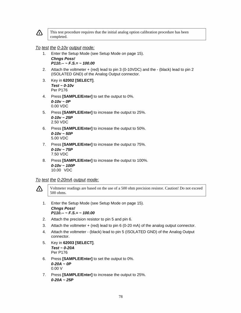
78
This test procedure requires that the initial analog option calibration procedure has been completed.
To test the 0-10v output mode: 1. Enter the Setup Mode (see Setup Mode on page 15).
Chngs Poss! P110.-- ~ F.S.= ~ 100.00
2. Attach the voltmeter + (red) lead to pin 3 (0-10VDC) and the - (black) lead to pin 2 (ISOLATED GND) of the Analog Output connector.
3. Key in 62002 [SELECT]. Test ~ 0-10v Per P176
4. Press [SAMPLE/Enter] to set the output to 0%. 0-10v ~ 0P 0.00 VDC
5. Press [SAMPLE/Enter] to increase the output to 25%. 0-10v ~ 25P 2.50 VDC
6. Press [SAMPLE/Enter] to increase the output to 50%. 0-10v ~ 50P 5.00 VDC
7. Press [SAMPLE/Enter] to increase the output to 75%. 0-10v ~ 75P 7.50 VDC
8. Press [SAMPLE/Enter] to increase the output to 100%. 0-10v ~ 100P 10.00 VDC
To test the 0-20mA output mode:
Voltmeter readings are based on the use of a 500 ohm precision resistor. Caution! Do not exceed 500 ohms.
1. Enter the Setup Mode (see Setup Mode on page 15).
Chngs Poss! P110.-- ~ F.S.= ~ 100.00
2. Attach the precision resistor to pin 5 and pin 6. 3. Attach the voltmeter + (red) lead to pin 6 (0-20 mA) of the analog output connector. 4. Attach the voltmeter - (black) lead to pin 5 (ISOLATED GND) of the Analog Output
connector. 5. Key in 62003 [SELECT].
Test ~ 0-20A Per P176
6. Press [SAMPLE/Enter] to set the output to 0%. 0-20A ~ 0P 0.00 V
7. Press [SAMPLE/Enter] to increase the output to 25%. 0-20A ~ 25P
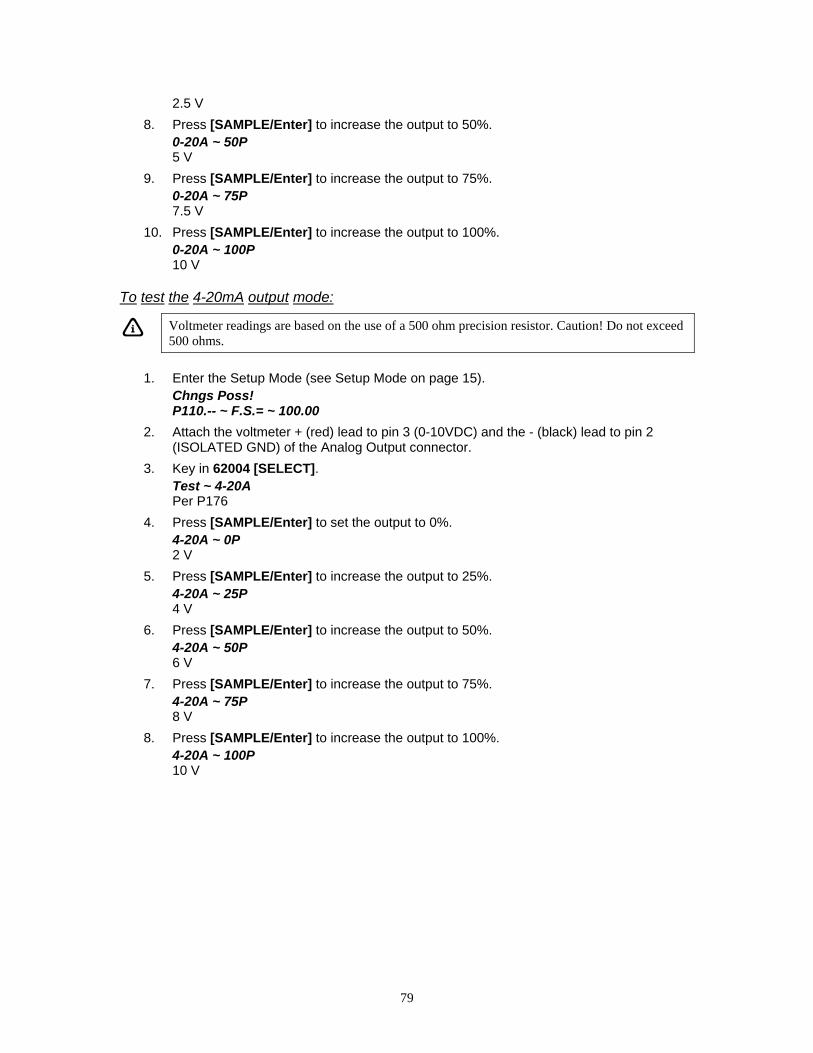
79
2.5 V 8. Press [SAMPLE/Enter] to increase the output to 50%.
0-20A ~ 50P 5 V
9. Press [SAMPLE/Enter] to increase the output to 75%. 0-20A ~ 75P 7.5 V
10. Press [SAMPLE/Enter] to increase the output to 100%. 0-20A ~ 100P 10 V
To test the 4-20mA output mode:
Voltmeter readings are based on the use of a 500 ohm precision resistor. Caution! Do not exceed 500 ohms.
1. Enter the Setup Mode (see Setup Mode on page 15).
Chngs Poss! P110.-- ~ F.S.= ~ 100.00
2. Attach the voltmeter + (red) lead to pin 3 (0-10VDC) and the - (black) lead to pin 2 (ISOLATED GND) of the Analog Output connector.
3. Key in 62004 [SELECT]. Test ~ 4-20A Per P176
4. Press [SAMPLE/Enter] to set the output to 0%. 4-20A ~ 0P 2 V
5. Press [SAMPLE/Enter] to increase the output to 25%. 4-20A ~ 25P 4 V
6. Press [SAMPLE/Enter] to increase the output to 50%. 4-20A ~ 50P 6 V
7. Press [SAMPLE/Enter] to increase the output to 75%. 4-20A ~ 75P 8 V
8. Press [SAMPLE/Enter] to increase the output to 100%. 4-20A ~ 100P 10 V


Model 370 & Model 375 Technical Reference Manual
Version 1.0
39-10-43145


