4
3D-Coordinate Measuring Machine (CMM) Technical Data XOplus 55/77/98

3D-Coordinate Measuring Machine (CMM)
Technical Data
XOplus 55/77/98

Short description
Application areas
Standard features
Probe systems
Software
Software options
Technical Data XOplus 55 / 77/ 98
Compact design operator workstation, with integrated CNC-bridge design measuring machine with touch--trigger
The Y-axis guide -way is machined directly into the base
CMM available in multiple sizes for the optimal selection of the
In production, quality control, process and production Both series and individual measurementPalletized operation possiblecontrol, in reverse engineering and model making
Geometric and free-form components
The X-and Y-guide-ways feature bellows protections against
Compact control panel with central, logarithmic joystick
Selectable joystick axis assignment. Wireless version optionally available
PH10M/PH10T motorized indexing head TP20 touch-triggr probe stylus module changeable via optional tool changerTP200 touch-trigger probe, highly precise and suitable
optional tool changer
access, network capabilities support the user
ISO 1101/ASME Y14. 5M
I+ +DME Server
QS-STAT interfaceInterpreter
Parasolid)
on CAD data
PH10M motorized indexing headSP25M scanning and single-point probe, precise and flexiblefor stylus lengths of up to 400mm. Probe module and stylus can be changed via optional tool changerShapetracer : 3D Line Scanner to report and handle point cloudsPhoenix II: Optical, non-contact 3D scanning probe, provide
Three-axis contouring controller with intelligent “look-ahead”
Integrated statistic functions, frequency distribution, trend
Shape-and location tolerances according to User dialog and reporting can be selected and switched
Context-sensitive online help in15 user languages
Numeric and graphic reporting of the measured results
Software package for free-form surfaces CAD direct interfaces (e.g. CATIA V4/V5, Pro-E, Unigraphics
SPC control charts, process capability cK and cPk, with the DMIS Import, DMIS Export, DMIS Reporting, DMIS Native
Export point and element data in VDA1 formatBlade analysis software package
Graphically interactive on-and offline programming on-line independently 15 languages
and evaluating geometry and free -form elements (option)User-friendly Windows based software for measuring
Graphic user interface featuring extensive automatism to
system “Grips” for measurement program creation based
“ mouse function” and context-sensitive function buttons
Pre-stressed, encompassing air bearings in all axes
SP80 scanning probe head, highly precise for probe lengthsup to 500mm. For scanning and single-point probing, stylus combinations can be changed via optional tool changer
Workpiece-oriented database, SQL-capable, with multi-user
function for application-optimised trajectory
combined friction power transmissionHigh-speed-dynamic servo drives with position monitoring
plate, providing optimal long-term stability
Passive vibration dampers
Manual temperature compensation (Automatic temperature compensation on all axes and work piece optionally available)
(override 0-100%) in all operation modes, resulting insensitiveTwo-stage speed selection and variable speed adjustment
movement via joystick or in CNC mode
required measurement volume
contamination
or scanning probe systems controller and computerAll granite guide-- ways are accurately hand--lapped
diadgram, machine-capability Cm and Cmk
Manual probe system available (PH6, MH20i, etc)PH20TM: Continuous 5-axis touch-trigger system with "head touch"
for styli up to 100mm in length. Styli can be changed via
field retrofittableActive pneumatic vibration damping optionally available and
fast efficient metrology solution for feature recognition andsurface analysis
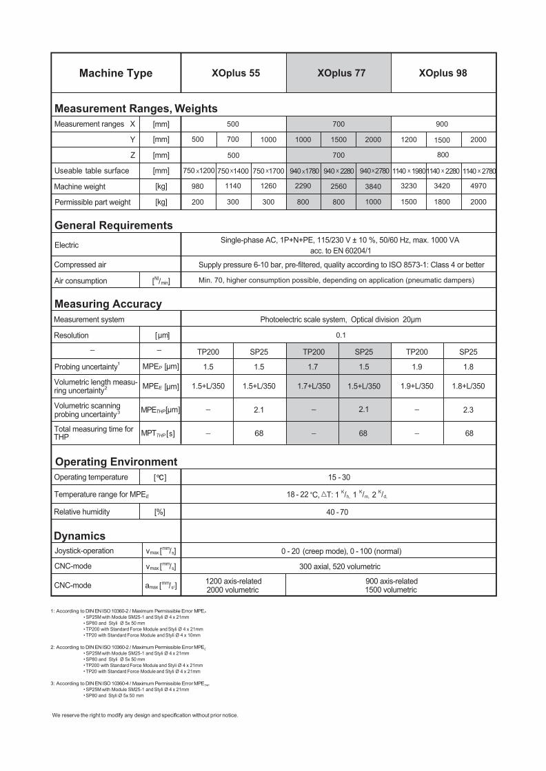
XOplus 55 XOplus 77 XOplus 98Machine Type
Measurement Ranges, Weights
General Requirements
Measuring Accuracy
Operating Environment
Dynamics
Measurement ranges X
Y
Z
Useable table surface
Single-phase AC, 1P+N+PE, 115/230 V ± 10 %, 50/60 Hz, max. 1000 VA
Supply pressure 6-10 bar, pre-filtered, quality according to ISO 8573-1: Class 4 or better
acc. to EN 60204/1
Photoelectric scale system, Optical division 20µmMeasurement system
Volumetric scanning
Total measuring time for
1200 axis-related
0 - 20 (creep mode), 0 - 100 (normal)
300 axial, 520 volumetric
900 axis-related1500 volumetric2000 volumetric
Temperature range for MPE
Operating temperature
Relative humidity
Joystick-operation
CNC-mode
CNC-mode amax
vmax
vmax
probing uncertainty
Volumetric length measu-ring uncertainty
Resolution
THP
Compressed air
Air consumption
Electric
Machine weight
Permissible part weight
[mm]
[mm]
[mm]
[mm]
[kg]
[kg]
500 700 900
800700500
1140 980
300200
1260
300
2290
800
2560 3840
1000 1800 20001500
3230 3420 4970
800
1000 1000 1500 1200 15002000 2000700500
750 X1700750 X1400750 X1200 940 X1780 940 X 2280 940 X2780 1140 X 1980 1140 X 2280 1140 X 2780
Min. 70, higher consumption possible, depending on application (pneumatic dampers)
0.1
mms
mms
mms2
E
[%]
c
2
3
[ ]
[ ]
NImin
μm
[ ]μm
[ ]μm
[ ]s
TP200 SP25 TP200 TP200SP25 SP25
1.5 1.5 1.7 1.5 1.9
2.32.12.1
68 68
15 - 30
40 - 70
18 - 22
68
1.8
1.5+L/350 1.5+L/350 1.7+L/350 1.5+L/350 1.9+L/350 1.8+L/350
Probing uncertainty1 [ ]μmMPEP
MPEE
MPE
MPT
THP
THP
C, T: 1 1 2Kh,/ K
m,/ Kd,/
SP25M with Module SM25-1 and Styli Ø 4 x 21mm
SP25M with Module SM25-1 and Styli Ø 4 x 21mm
SP25M with Module SM25-1 and Styli Ø 4 x 21mmSP80 and Styli Ø 5x 50 mm
SP80 and Styli Ø 5x 50 mmTP200 with Standard Force Module and Styli Ø 4 x 21mmTP20 with Standard Force Module and Styli Ø 4 x 10mm
SP80 and Styli Ø 5x 50 mmTP200 with Standard Force Module and Styli Ø 4 x 21mmTP20 with Standard Force Module and Styli Ø 4 x 21mm
1: According to DIN EN ISO 10360-2 / Maximum Permissible Error MPEP
2: According to DIN EN ISO 10360-2 / Maximum Permissible Error MPEE
We reserve the right to modify any design and specification without prior notice.
3: According to DIN EN ISO 10360-4 / Maximum Permissible Error MPETHP
No. 219, Song Xiu Road, Qingpu, Shanghai 201703Tel :+ 86 21 5970 3088Fax:+86 21 5970 [email protected]
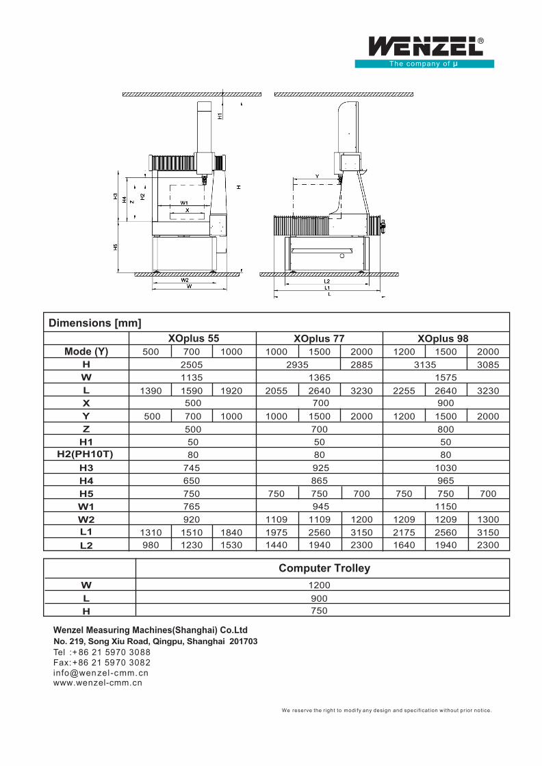
Dimensions [mm]
Computer Trolley
XOplus 55
H2(PH10T)
HWLX
YZ
H1
H3H4H5
H
W1
W
W2L1
L
L2
Mode (Y)XOplus 77 XOplus 98
70050025051135
1390 1590 500
745650
765920
1310 15101230980
18401530
750
1000 700 500
1920
1000 1000 1500 2000 1200 1500 200030853135
15752255 2640 3230
9001200 1500
1030
2000800
288529351365
2055 2640 3230 700
925965
750 7501150
12092175 2560 31501640 1940 2300
1209 1300
700865
750 750 700
1000
1200900750
1500
94511091975
1109 12002560 3150
1440 1940 2300
200070050 5080 80
50 80
500
We reserve the r ight to modify any design and speci f icat ion without pr ior not ice.
www.wenzel-cmm.cn
Wenzel Measuring Machines(Shanghai) Co.Ltd


