Page 1
SEMINAR’06 3D DOCTOR
ABSTRACT
3D-DOCTOR Software is used to extract information from image files to
create 3D model. It was developed using object-oriented technology and provides efficient tools to
process and analyze 3D images, object boundaries, 3D models and other associated data items in an
easy-to-use environment. It does 3D image segmentation, 3D surface modeling, rendering, volume
rendering, 3D image processing, disconsolation, registration, automatic alignment, measurements, and
many other functions.3D-DOCTOR supports both grayscale and color images stored in DICOM, TIFF,
Interfile, GIF, JPEG, PNG, BMP, PGM, RAW or other image file formats. 3D-DOCTOR creates 3D
surface models and volume rendering from 2D cross-section images in real time on your PC. Leading
hospitals, medical schools and research organizations around the world are currently using 3D-
DOCTOR.
Download your Full Reports for 3D Doctor @ 123seminarsonly.com
Page 2
SEMINAR’06 3D DOCTOR
CONTENTS
INTRODUCTION
3D DOCTOR BASICS
STEPS TO CREATE 3D RENDERING FROM 2D IMAGE SLICES
3D FORMATS, HANDLING, AND RESLICING
3D SURFACE RENDERING
ABLE SOFTWARE UPGRADES 3D DOCTOR
MEASUREMENTS DONE BY 3D DOCTOR
3D MEASUREMENTS
ADVANCE 3D IMAGE PROCESSING
3D IMAGE FUSION
PLATFORMS 3D DOCTOR RUNS
CONCLUSION
REFERENCES
Download your Full Reports for 3D Doctor @ 123seminarsonly.com
Page 3
SEMINAR’06 3D DOCTOR
INTRODUCTION
3D-DOCTOR is an advanced, 3D imaging software developed by
Able Software Corp.It is an advanced 3D modeling, image processing and measurement software for
MRI, CT, PET, microscopy, scientific, and industrial imaging applications. 3D-Doctor supports both
grayscale and color images stored in DICOM, TIFF, Interfile, GIF, JPEG, PNG, BMP, PGM, RAW or
other image file formats. 3D-DOCTOR creates 3D surface models and volume rendering from 2D
cross-section images in real time on your PC. You can export the polygonal mesh models to STL,
DXF, IGES, 3DS, OBJ, VRML, XYZ and other formats for surgical planning, simulation, quantitative
analysis and rapid prototyping applications. You can calculate 3D volume and make other 3D
measurements for quantitative analysis. 3D-DOCTOR's vector-based tools support easy image data
handling, measurement, and analysis.3D CT/MRI images can be re-sliced easily along an arbitrary
axis. Multi-modality images can be registered to create image fusions. Misaligned slices can be
automatically or semi-automatically aligned using 3D-DOCTOR's image alignment functions. Other
image processing functions include template-based film cropping, image reslicing to correct slices of
uneven thickness, volume resizing, and image rotation.The 3DBasic scripting tool makes it easy to
create Basic-like sophisticated 3D imaging programs.This software does 3D image segmentation, 3D
surface modeling, rendering, volume rendering, 3D image processing, deconvolution, registration,
automatic alignment, measurements, and many other functions.
3D-DOCTOR supports a variety of image formats in both 2D and 3D. These formats
include DICOM, TIFF, JPEG, BMP, Interfile, GIF, PNG and RAW. Other non-standard image
formats are also supported, but only with known dimensions (number of columns, rows and planes),
bit depth per pixel, little endian or big endian, and the size of file header. 3D-DOCTOR is currently
Download your Full Reports for 3D Doctor @ 123seminarsonly.com
Page 4
SEMINAR’06 3D DOCTOR
being used by leading hospitals, medical schools and research organizations around the world.
3D- DOCTOR Basics
3D- images such as CT, MRI and microscopy images. The following lists some of the main
differences between 3D-DOCTOR and other packages: DOCTOR uses its unique vector-based
technologies to create better 3D models from volumetric
➢ Unique vector-based technologies for better 3D model creation and easy editing.
➢ Surface model uses smaller number of triangles while maintaining all details for high
quality rapid prototyping applications.
➢ Smart memory management with no limit for the number of slices to be used. It has
been used to process images with over 2000 slices on a PC with only 256MB RAM.
➢ Single command volume calculation and quantitative analysis report
➢ Handles DICOM and other image formats, such as TIFF, JPEG, PNG, GIF,
BMP, Interfile and RAW (vendor proprietary formats).
➢ Works with both grayscale and color images (color classification and separation)
➢ Supports CT, MRI, PET, microscopy, industrial CT, scanned film images, boundary
slices, slice data and XYZ points.
➢ High End 3D Image Processing Functions: image registration for multi-modality
application, image fusion, image resizing, image reslicing, etc.
➢ Write your own programs with 3DBasic script to automated frequently used steps.
➢ 3D Output Formats: STL (ASCII and Binary), VRML, DXF, 3D Studio, IGES,
Wavefront OBJ and more.
➢ Software Reliability: No known bugs in our products because we fix them right away
once they are reported.
Download your Full Reports for 3D Doctor @ 123seminarsonly.com
Page 5
SEMINAR’06 3D DOCTOR
➢ Reasonably priced.
Steps to create 3D rendering from 2D image slices
The following lists the main 3D-DOCTOR functions and steps youcan use to create 3D rendering
from your 2D image slices:
1. File/New Stack to add the slices to the stack list and open it.Or the File/Open command if the slices
are already in a list or a single image file.
2. Function Keys F2 and F3 to zoom in and out. F5 and F6 to switch to the previous and next image
slice. Click on the animation tool bar to fly through the slices. View/Image Contrast to adjust display
contrast, etc.
3. Edit/Calibrations to enter image spatial/spectral resolution.
4. Edit/Object Settings to add new object groups for holding the boundary
data.
5. Use 3D Rendering/Auto Segment and define the number of objects
to be segmented for fast automatic segmentation. You can ase the 3D Rendering/Interactive Segment
or Edit/Boundary Editor to trace object boundaries automatically or manually. The boundary data will
be used by the following steps.
6. Use the 3D Rendering/Surface Rendering commands to create 3D
surface models. When the 3D surface models are displayed, use
View/Object to change the transparency and color properties and functions
under Tools submenu for further analysis.
7. Use the 3D Rendering/Volume Rendering to create 3D volume rendering
for 3D visualization.
Download your Full Reports for 3D Doctor @ 123seminarsonly.com
Page 6
SEMINAR’06 3D DOCTOR
8. Use Edit/Object Report and Boundary Report to get quantitative analysis of your image
3D Formats, Handling, and Reslicing
Image formats that 3D-DOCTOR support and which can be used:
3D-DOCTOR supports a variety of image formats in both 2D and 3D. These formats
include DICOM, TIFF, JPEG, BMP, Interfile, GIF, PNG and RAW. Other non-standard image
formats are also supported, but only with known dimensions (number of columns, rows and planes),
bit depth per pixel, little endian or big endian, and the size of file header.3D-DOCTOR can process a
wide variety of images, including CT (computed tomography), MRI (magnetic resonance imaging),
microscopy, industrial CT, seismic wave data, scientific volume data, 3D contours, and 3D cloud
points. Images can be obtained from medical imaging devices or scanned from films or other image
sources. 3D-DOCTOR supports TWAIN-compatible imaging devices and functions for cropping
medical film images.3D-DOCTOR supports grayscale images in 4, 8, 12 and 16 bits, 1-bit black/white
images, and 8 and 24 bit color images.
3D formats that 3D-DOCTOR support:
3D surface models created using the surface rendering commands can be saved as AutoCAD
DXF, IGES, STL (ASCII and Binary), 3D Studio 3DS, VRML, Wavefront OBJ, raw triangles, and
3D-DOCTOR's own binary format.3D models created by 3D-DOCTOR are polygonal models, not
NURB (non-uniform rational B-splines) models. The models are saved in the form of surface polygons
and triangles when exported to the above formats, including IGES. Many NURB based CAD software
supports polygonal model and have functions to import them as surface body, solid body or graphics
model. There are also software tools available to convert a polygonal model to a NURB modeI
Download your Full Reports for 3D Doctor @ 123seminarsonly.com
Page 7
SEMINAR’06 3D DOCTOR
Limit on image size
3D-DOCTOR can handle very large 3D volume images thanks to the efficient memory
management implementation. 3D-DOCTOR does not load an entire 3D volume into memory for
processing, instead it only keeps what's needed in memory to get the best performance. 3D-DOCTOR
is designed to handle image sizes way above what today's scanners can produce.It is always
recommended to add more memory (RAM) to reduce disk swapping an erformance. 256MB RAM
should be a reasonable point for most 3D medical images. Images are brought into 3D-DOCTOR by
file. You can read an image file directly from a server where the image is stored when direct network
access is available. If direct access is not available, you can copy the image file to a removable
storage media (ZIP disk, CD, or tape) and then move the data file to the system where 3D-DOCTOR
is installed. Read the image file into 3D-DOCTOR and start from there.If your image is on multiple
films where each film has a matrix of slices, then simply scan the films using a regular image scanner
with a transparency kit or a film scanner. Bring the scanned images into 3D-DOCTOR and then use
the template based Crop Film command to separate the slices for 3D visualization with just a few
simple mouse clicks.
Color images can be processed using 3D-DOCTOR,. It supports both 24-bit and 8-bit
color images. The 3D Rendering/Segment Object function lets you segment both color and grayscale
images to get object boundaries. You can also use the Image/Processing/Color Classification function
to group the colors and then extract boundaries using the segmentation function. Color images can also
be used in 3D Volume Rendering. Can convert color images to grayscale using the Image/Conversion
Download your Full Reports for 3D Doctor @ 123seminarsonly.com
Page 8
SEMINAR’06 3D DOCTOR
function.
Import raw image files from the Visible Human Project:
3D-DOCTOR can import the raw images files from the Visible Human Project for 3D
rendering and modeling. Many 3D-DOCTOR users have successfully used the datasets to create
anatomical model for research, education, product design, finite element analysis and other
applications. The Visible Human Project is the creation of complete, anatomically detailed, three-
dimensional representations of the normal male and female human bodies. Acquisition of transverse
CT, MR and cryosection images of representative male and female cadavers has been completed. The
male was sectioned at one millimeter intervals, the female at one-third of a millimeter intervals.
To import the files, use the "File/Raw Image File Import/Multiple Files" command. Add the raw data
files to the list and enter the image size information (described in the README.TXT file in the image
file folder).
For example, if you are importing the color raw image files, the parameters will be entered like
this:
Number of Columns: 2048
Number of Rows: 1216
Bits Per Pixel: 8
Number of Bytes to Skip: 0
Photometric Display: RGB Color
Little Endian: checked
For the Calibration: X, Y are 0.33mm, Z = 1 mm
Download your Full Reports for 3D Doctor @ 123seminarsonly.com
Page 9
SEMINAR’06 3D DOCTOR
Here is a screen shot of the color image imported into 3D-DOCTOR and models created
Deconvolution
Image deconvolution is used to remove or reduce degradations caused in the imaging
process. These include the blurring introduced by optical systems and by image motion, as well as
noise due to electronic and photometric sources. 3D-DOCTOR provides two types of deconvolution to
restore degraded 3D images, one is a Fast Nearest Neighbor deconvolution and the other is an iterative
Maximum Entropy deconvolution method.
Download your Full Reports for 3D Doctor @ 123seminarsonly.com
Page 10
SEMINAR’06 3D DOCTOR
3D SURFACE RENDERING:
D-DOCTOR's, 3D surface rendering commands create 3D surface models from object
boundary lines or contours. The 3D surface model consists of triangle faces. Multiple objects can be
combined together using 3D surface rendering.There are 2 surface rendering commands in 3D-
DOCTOR: Simple Surface Rendering and Complex Surface Rendering. They both create 3D surface
model but use different algorithms and are suitable for different objects. The simple surface rendering
uses a proprietary algorithm to create smooth and simpler surface models. This method is fast and the
models are better suited for rapid prototyping and volume calculation applications. The complex
surface rendering uses a triangulation algorithm. This method is slow but robust, and is better for
rendering objects with complicated branches and topologies. With 3D-DOCTOR, you can select the
proper rendering method for an object and mix multiple objects created using different rendering
methods for 3D display.
How to adjust the scale (X, Y, Z) of my 3D rendering
When you create a 3D rendering with only a few slices, the 3D rendering may appear as a
very thin object because, by default, 3D-DOCTOR assumes the slice thickness (or distance between
slices) is the same as the pixel size in the XY plane (column and row).
This can be adjusted easily by using the Edit/Calibrations command. At the dialog box, enter the
values for X, Y, and Z. The X and Y are the size of a pixel within a slice. The Z value is the slice
thickness plus the distance or gap between slices. If you need to increase the slice thickness, enter a
larger value for Z so its scale will be adjusted automatically in the 3D rendering. If you know the size
in all dimensions and the physical unit, you can enter them in the Image Calibration Parameters dialog
box, and surface area. the correct scaling will be applied when making measurements and calculating
3D volume and surface area.
Download your Full Reports for 3D Doctor @ 123seminarsonly.com
Page 11
SEMINAR’06 3D DOCTOR
Creating 3D surface model from images
The following steps explain the process of creating a 3D surface model from images.
Step 1. Open the 3D image using the File/Open Image command.
Step 2. Segment the image using one of the segmentation commands to generate boundaries for an
object.
Step 3. Edit the boundary lines using the Edit/Boundary Editor, if necessary. Use the
File/Boundary/Export Boundary command to save the boundary data to a file. If you need to render
only part of an object, you can use the 3D Rendering/Split Object command to split the object along an
arbitrary axis.
Step 4. Now you can create a 3D surface rendering using the 3D Rendering/Surface Rendering
commands. You can also create a volume rendering using the 3D Rendering/Volume Rendering
command.
Split or Cut objects for 3D rendering
With 3D-DOCTOR, an object defined by object boundaries can be cut or split into smaller
objects.
The following are the steps required for cutting or splitting objects:
Step 1. Activate the image plane window where the object boundary is displayed. Select the 3D
Rendering/Split Object command. The cursor will change to a cross. Move the cursor to the starting
location of the cutting line and click the left mouse button. Now you'll see a rubber band line which
connects the cursor to the starting location. Move the cursor to the ending location and click the left
mouse to define the line. A dialog box appears to let you select the range of image slices to be cut.
Select the option "Only keep object on the right" to keep the split object on the right side of the cutting
Download your Full Reports for 3D Doctor @ 123seminarsonly.com
Page 12
SEMINAR’06 3D DOCTOR
line or uncheck it to keep objects on both side.
Step 2. Once the new object boundaries are cut, use Edit/Object Settings to turn off objects that are not
to be used for 3D rendering. Now select a 3D rendering (surface or volume) command to create the 3D
rendering of the split object
3D DOCTOR Software has been one of the tremendous analysis software that I use on a
regular bases to extract information from image files to create 3D model.
Step 1. Open Image Step 2. Interactive Segmentation Step 3. Creating 3D Model
Computed tomography (CT) is an imaging technique that uses special x-ray equipment to obtain cross-
sectional images of the body. A CT image normally has different pixel intensity range for tissues such
as bones, organs and other tissues. The threshold-based "Interactive Segmentation" provides an easy
way to segment a CT image for 3D modeling.
A 3D mesh model can be created from a CT image in 3 main steps
Step 1. Open the CT image. If the image slices come in as separate files, use the "New Stack"
command.
Step 2. Use the "Interactive Segmentation" to generate object boundaries. For small size soft tissues,
the manual tracing method can also be used. Boundaries can be edited using the boundary editor.
Download your Full Reports for 3D Doctor @ 123seminarsonly.com
Page 13
SEMINAR’06 3D DOCTOR
Step 3. Create 3D mesh models using the surface rendering command. The models can be exported ,
STL (ASCII and Binary), DXF, VRML, 3DS, OBJ, PLY and other formats for 3D measurement,
rapid prototyping , simulation, treatment planning and other applications
ABLE Software upgrades 3D-DOCTOR
ABLE Software Corp. has announced a new version of its 3D-DOCTOR software for vector-
based 3D imaging, modeling and measurement of CT (computed tomography), MRI (magnetic
resonance images), microscopy and volumetric image features an enhanced modeling algorithm for
quicker rendering and higher quality models; polygon-based mesh models are created from CT/MRI
images in DICOM (Digital Imaging and Communications in Medicine); the new 'smooth shading'
volume rendering can be used for real-time 3D image visualization; color and grayscale are supported;
and new boundary tracing functions have been developed to speed and ease object boundary definition
using a touch screen or a tablet..
ABLE released a new version of 3D-DOCTOR
ABLE Software has released a new version of 3D-DOCTOR, the vector-based 3D imaging,
modeling and measurement software for CT, MRI, microscopy and volumetric images, the company.
In this new version, an interactive 3D image registration function is implemented to register images of
different modalities, such as CT, MRI and PET. The registration function displays both the source and
the target image in 3D and interactively adjusts (rotate, move and stretch) the source image until it fits
the target the image. A control point based registration function is also available for multi-modality 3D
Download your Full Reports for 3D Doctor @ 123seminarsonly.com
Page 14
SEMINAR’06 3D DOCTOR
image registration and fusion.
The 3D surface modeling algorithm has been enhanced to provide faster rendering and
generate high quality 3D mesh models from CT/MRI scans. 3D models are used for 3D measurement,
volume calculation, surgical and treatment planning, surgical simulation, and 3D rapid prototyping
applications.
A new animation function is implemented to create movies and 3D simulations from 3D
rendering. The tissue display properties can be set as transparent, opaque, wire frame or with texture
map during the animation. Objects can be moved, scaled, hidden or made visible in the animation
process.
The upgraded volume rendering function creates real-time 3D image visualization. It supports both
color and grayscale rendering using either opaque or transparent voxels. The volume rendering uses
either the entire image volume, a portion defined by regions of interest (ROI), or a portion defined by
the user interactively. Tissues with different density can be included or excluded in the rendering by
changing their opacity property.
3D-DOCTOR is an advanced 3D imaging software for researchers doing medical, industrial,
engineering and other imaging applications. Right from your desktop PC, you can visualize 3D image
data (CT, MRI, microscopy, ultrasonic and other volumetric data), quickly extract object boundaries
using both fully automatic and interactive 3D image segmentation, create both 3D surface and volume
rendering, in just few easy steps.
Download your Full Reports for 3D Doctor @ 123seminarsonly.com
Page 15
SEMINAR’06 3D DOCTOR
Measurements Done By 3D DOCTOR
3D-DOCTOR can make a variety of image measurements, including distance, area, surface
area, volume, profile, and image region histogram. 3D-DOCTOR lets you measure angles using the
Angle Measurement tool. 3D volumes of 3D surface models can be calculated easily. When the
surface model window is displayed, use the Process/Calculate Volumes command.
For image measurement, 3D-DOCTOR allows you to measure distance, thickness, area of a
region, surface area, volume, image density profile and image histogram of a region in any shape.
With 3D-DOCTOR, you not only have a number of different ways to visualize your 3D image in 2D,
3D, montage, surface and volume, but also the tools necessary to do accurate quantitative analyses for
your applications.
3D-DOCTORÆs restoration functions are the solution to de-blur and restore the 3D image to
its original quality with either fast nearest neighbor or maximum entropy deconvolution. It is a
complex mathematical problem, but 3D-DOCTOR makes it easy to solve.
3D-DOCTORÆs image registration function, you can register or geometrically correct a 3D
image by giving 4 or more control points, easily combine two registered images using one of 8
available methods to create a fusion image.
Download your Full Reports for 3D Doctor @ 123seminarsonly.com
Page 16
SEMINAR’06 3D DOCTOR
The 3D volume of 3D surface model
The volume of a 3D surface model can be calculated easily using the Process/Calculate
Volume command within the surface model window. This command computes both volume and
surface area. To adjust the scale and unit for volume calculation, the scaling parameters should be
entered using the Edit/Calibration command before rendering is done.If you have your 3D model
saved in a format supported by 3D-DOCTOR, such as DXF, STL, raw triangle, etc., you can use
File/Open Model to read the 3D model into 3D-DOCTOR and then calculate the volume
3D Printing and Rapid Prototyping for Surgical Simulation and Treatment
Planning Applications
3D solid and surface models can be created from any types of volumetric images for modeling
and rapid prototyping applications. The 3D models can be exported to AutoCAD DXF, IGES, STL for
rapid prototyping, OBJ and 3DS for 3D animation.
This example shows a skull model printed using a 3D printer from the STL file generated by
3DDOCTOR. Magnetic resonance imaging (MRI) produces high quality images of the human body.
3D-DOCTOR exports 3D models to STL (both ASCII and Binary) for rapid prototyping machines, as
well as DXF for AutoCAD, 3DS for 3DStudio, Wavefront OBJ, and VRML for viewing on the
Internet by others. Once you have created 3D mesh models in 3D-DOCTOR, you can print them out
using a 3D printer and a rapid prototyping machine. If you do not have access to a 3D printer, there are
many service bureaus that can provide printing service.
Download your Full Reports for 3D Doctor @ 123seminarsonly.com
Page 17
SEMINAR’06 3D DOCTOR
3D Model Examples
3D Mesh Model Generated by 3D-DOCTOR 3D Output from a 3D Printer
3D Volume Calculation, Measurements and Quantitative Analysis
3D-DOCTOR provides an extensive set of tools for 3D volume calculation, measurement and
quantitative report. Thanks to the vector-based architecture, the 3D volume and surface area of an
object can be easily calculated with just a single command.
Download your Full Reports for 3D Doctor @ 123seminarsonly.com
Page 18
SEMINAR’06 3D DOCTOR
3D Measurements:
➢ Object volume
➢ Object surface area
➢ Length on 3D object
➢ Digitize 3D points
➢ Crop 3D object
➢ Cut 3D object
Object Measurements:
➢ Total pixel density
➢ Average pixel density
➢ Area and volume
➢ Number of objects
➢ Min and max pixel density
➢ Calibrated density
➢ Variance and standard deviation
➢ Histogram data
Display image slices together with 3D models
3D-DOCTOR can easily displays the image slices together with your 3D models. If you have
a surface model display window open, use the View/Image Planes command to turn on the image
plane display. You can use the View/Image Settings command to change the transparent and opaque
properties and individual plane display status.
Download your Full Reports for 3D Doctor @ 123seminarsonly.com
Page 19
SEMINAR’06 3D DOCTOR
Advanced 3D Image Processing
3D Computed Tomography: Create parallel cross-section, volume images using x-ray images
taken at angles around an object. Turn your x-ray machine into a full CT system using 3D-DOCTOR.
Other image processing functions include: template-based scanned film cropping, volume
resizing, 3D image filtering, Image rotation, orientation adjustment, contrast adjustment, background
removal, image combination, linear feature extraction, pattern recognition, segmentation, image
mosaic, and color classification can all be performed on your 3D images.
3D Image Restoration by Deconvolution: 3D-DOCTOR provides two highly efficient
deconvolution methods for 3D image restoration and reconstruction, a fast nearest neighbor algorithm
and an iterative maximum entropy algorithm.
3DBasic scripting language will let you create your own Basic-like sophisticated programs
using 3D-DOCTOR's advanced imaging and rendering functions quickly.
Deconvolution of an image from Hubble Space Telescope
THE BASICS
Download your Full Reports for 3D Doctor @ 123seminarsonly.com
Page 20
SEMINAR’06 3D DOCTOR
3D-DOCTOR was developed using object-oriented technology and provides efficient tools to
process and analyze 3D images, object boundaries, 3D models and other associated data items in an
easy-to-use environment.
The main steps to create 3D models and volume rendering from a 2D slice images (CT, MRI,
microscopy): 1) Open the 3D image, which is displayed by a single plane window and a montage
window with all slices. 2) Define objects and create object boundaries for each object. 3) 3D surface
rendering and volume rendering.
The following explains each step and commands used:
Step 1. Open a 3D image. If your 3D image is stored in a series of DICOM files or in a format that's
directly supported (DICOM, TIFF, BMP, PNG, JPG, raw image data with a header *.HDR), you can
use the File/New Stack command to put the files into a stack list and open it.
This Figure shows an opened CT pelvis image:
Download your Full Reports for 3D Doctor @ 123seminarsonly.com
Page 21
SEMINAR’06 3D DOCTOR
If the image format is not directly supported, use the File/Raw Image File Import command to
add a header or multiple header files and then open the image data files.
If your image is on a film, for example, one film has 12 slices, you can scan the film using a scanner
and then use the Image/Crop Image/Crop Region command to crop each slice and save a separate file
using the File/Save/Save Image As command. Once you have the image files, then use the File/New
Stack command to create the 3D stack list. All slices must be cropped to the same size so they can be
put together as a 3D image for further processing.
Volume Rendering:
If you need to do a 3D volume rendering, you can use the "3D Rendering/Volume
Rendering/Smooth Rendering" command now. If you want to render different tissue range, go back to
the image display,
adjust the contrast and then do a volume rendering again.
Step 2. Define objects and create boundary lines for each object. Use the Interactive Segment
command to trace object boundaries interactively or the Auto Segment for fully automatic object
boundary detection.
Download your Full Reports for 3D Doctor @ 123seminarsonly.com
Page 22
SEMINAR’06 3D DOCTOR
Interactive Segmentation:
Once the interactive segmentation starts, the image plane display is refreshed to apply color to
pixels that fall within the threshold range specified by the Min and Max values. Use the slider bar to
adjust the Min and Max values. The display of the image slice is updated in real-time according to the
current threshold selection. When pixels that belong to the intended object are displayed in color, you
can click the “Segment Plane” button to extract the boundaries for the current image plane. Use the
“Next Plane” or “Prev Plane” button to go through other planes to segment them individually. If the
threshold values are applicable to all slices, you can click on the “Segment All” button to extract
boundaries for all image slices. Click “Finish” to leave the interactive segmentation function.
Download your Full Reports for 3D Doctor @ 123seminarsonly.com
Page 23
SEMINAR’06 3D DOCTOR
Auto Segmentation:
This figure shows the image segmented using the Auto Segment command
with the number of objects defined as 2.
Since Auto Segment command segments the entire image, including the background, you will
need to use the Edit/Object Settings command to turn off some of the objects that are not of interest
before surface rendering or volume rendering is performed. Boundary lines can be edited using the
Boundary Editor under the Edit menu or processed using the boundary line processing functions under
the Edit/Boundary Process menu. Boundary lines are organized by object groups for more effective
management and more flexible use by the rendering functions. You can use the Object Report to get
detailed quantitative analysis of the objects.
Step 3. When boundary lines are generated, use 3D surface rendering to create 3D surface models or
Download your Full Reports for 3D Doctor @ 123seminarsonly.com
Page 24
SEMINAR’06 3D DOCTOR
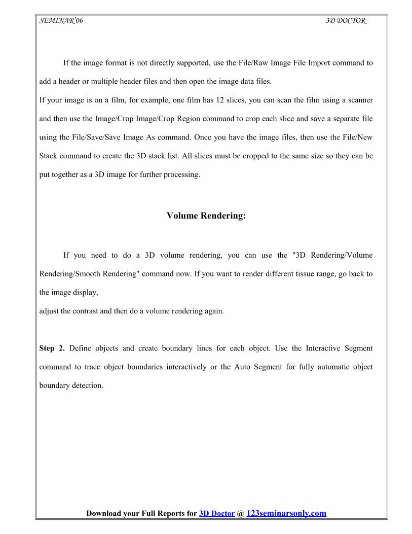
3D volume rendering. The 3D models can be exported to many 3D formats for simulation, animation,
rapid prototyping, quantitative analysis and other applications.we can also calculate the volume using
the Tools/Calculate Volume command and the Tools/Measure to make 3D measurements on the
model.
This figure shows the model created for the bone structure.
3D Mesh Modeling from CT, MRI and other Images
Input Image: CT, MRI, PET and other cross-sectional images in DICOM, TIFF, BMP, JPEG,
Interfile, PNG, PGM, GIF, Raw Image Data, and other uncompressed image formats. Image files in
various vendor specific formats can be easily read using 3D-DOCTOR's universal image configuration
and input function. Both grayscale (8-bit and 16-bit) and color images are supported. Scanned CT/MRI
films can easily be cropped using the template-based function for 3D imaging applications.
Download your Full Reports for 3D Doctor @ 123seminarsonly.com
Page 25
SEMINAR’06 3D DOCTOR
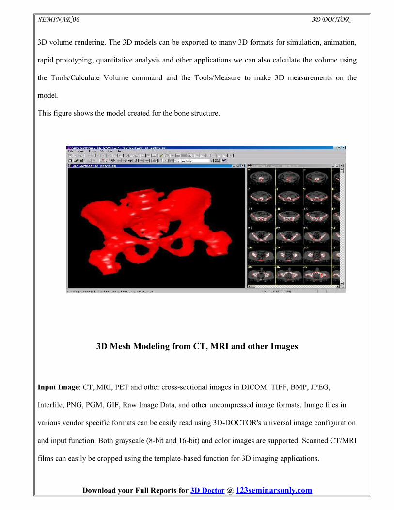
Pelvis CT Image Head MR Image with Brain Tumor
Segmentation Tools: the fully automatic texture-based segmentation for grayscale and color images,
the thresholding-based Interactive Segmention for CT images, the region-based Object Segmentation
and the easy-to-use polygon-based manual tracing.
3D Model Export: STL (ASCII and Binary), AutoCAD DXF, 3D Studio (3DS), IGES, VRML,
Wavefront OBJ, PLY, raw triangles, and other 3D graphics file formats for rapid prototyping, 3D
printing, finite element analysis, animation and visualization applications Once object boundaries are
generated from segmentation, 3D mesh models are created in using one of the surface rendering
functions. Unlimited number of objects representing different tissues are supported .
Download your Full Reports for 3D Doctor @ 123seminarsonly.com
Page 26
SEMINAR’06 3D DOCTOR
3D IMAGE FUSION
3D-DOCTOR provides several powerful image fusion functions to combine multi-modality
images together for analysis and visualization. There are 3 types of image fusion functions: 1) Color
Fusion: uses each image source as a color component (red, green, and blue) and creates a full color
image as the result. 2) Focus Fusion: eliminates the problems of limited depth of field by automatically
capturing the in-focus regions from a range of focal planes and combining them into a single fully-
focused, high resolution image. 3) Fusion: combines two images with one of the mathematical
operators: Add, Subtract, OR, AND, XOR, MAX, MIN, Transparent, etc. 4) Plane Fusion: combines
image slices into a single slice image by using the average, minimum, or maximum method.
1) Color Fusion
The following shows some color image fusion examples using multi-modality image sources.
A.) Image Fusion of CT and MRI Images
The color image window on the left is the fusion result created from the CT liver image and the
MRI liver image. The CT image is used as the red color component and the MRI image as the green
color component. A third image may also be used as the blue color component if available
Download your Full Reports for 3D Doctor @ 123seminarsonly.com
Page 27
SEMINAR’06 3D DOCTOR
B.) Image Fusion of CT and PET Images
The image on the left is a CT image. The image in the middle is a PET image. The image on the right
is
the fused image by using the CT as the background and the PET image as the blue color.
Download your Full Reports for 3D Doctor @ 123seminarsonly.com
Page 28
SEMINAR’06 3D DOCTOR
2) Focus fusion
Focus Fusion uses a proprietary image processing algorithm developed by Able Software to
eliminate the problems of limited depth of field by automatically capturing the in-focus regions from a
range of focal planes and combining them into a single fully-focused, high resolution image. No
knowledge with your image acquisition system is required for this processing.
3) Fusion
Two registered images can be combined to create a fusion image. This is often used to combine
two images acquired differently but from a single source to enhance the display of various materials or
tissues. For example, a CT image and an MRI image from the same patient can be combined to show
both bones and fat clearly in a single image. Much more information can be visualized in the
combined image than from the individual ones.
This picture shows how the fusion command is used.
Download your Full Reports for 3D Doctor @ 123seminarsonly.com
Page 29
SEMINAR’06 3D DOCTOR
➢ Plane Fusion:
You can combine multiple image slices into a single slice image using one of
the methods: minimum, average and maximum.
The following example shows the fusion image of a MRI knee image.
The window on the right is the fusion image by taking average of all slices. The window on the left is
the original image slices
Virtual doctor trains patients in 3D
The latest 3D web technology is being used to allow women to look out for problems such as
osteoporosis, heart disease and breast lumps.
US-based Superscape have produced a 3D virtual reality browser which allows visitors to their site to
watch, or even interact with informative presentations - viewing them from any angle.
Download your Full Reports for 3D Doctor @ 123seminarsonly.com
Page 30
SEMINAR’06 3D DOCTOR
Personal details taken
The sections of the site devoted to heart disease and osteoporosis allow the visitor to enter personal
health details - then see a 3D representation of the results, whether good or bad.
So a smoker who admits to having a poor diet and taking little exercise might see a heart artery
pumping slowly because it is clogged with fatty deposits.
And someone who does not drink enough milk, or a young person who diets too much, might be
depicted as a stooping figure because of the effects of osteoporosis.
The site aims to teach women how to carry out their own breast examinations, allowing viewing to
take place from any angle. Ben Green said: "The information we are conveying is already available to
the general public through leaflets - this provides the ability for concerned people to check out some of
the basics, and if they're still concerned after that, to go and see a doctor."
He is hopeful that the technology could eventually be used in hospitals to guide patients through
exactly what is going to happen during their operation, and perhaps even to help train medical
students.
Virtual reality has already been used to help doctors learn the skills of brain surgery by offering a 3D
image of a patient's head which can be operated on with a "software scalpel".
Superscape are well known for their innovative 3D virtual reality software - in the past, they have
produced 3D shopping malls, a virtual medieval garden and even a virtual graveyard.
Visitors to the site will have to download the browser and should be running at least a 133 MHz
Pentium processor.
Download your Full Reports for 3D Doctor @ 123seminarsonly.com
Page 31
SEMINAR’06 3D DOCTOR
Download your Full Reports for 3D Doctor @ 123seminarsonly.com
Page 32
SEMINAR’06 3D DOCTOR
3D DOCTOR
Connecting Engineers
The problem
B-rep modeling (boundary representation) is presently the most efficient tool for the
representation of 3D CAD objects (solids or surfaces). There exists today a consensus around the
STEP standard for the exchange of topological entities (solids, shells, faces,…) and geometric entities
(circles, cones, Bezier, Nurbs, B-spline, cylinder,…), but there is no accepted standard to check if a
definition is valid or not. The different modelers, and even the different functions of the same modeler,
have different tolerance values regarding "defective definition". For instance, a badly defined face with
an open trimming loop will be displayed as curves
The solution
3D DOCTOR is the most productive tool in the market that allows the automatic correction of
some of the flaws you may encounter. This will enable a greater number of functions and modelers to
accept the validity the definition of objects without changing their geometry. n't be shown in solid
mode.
And more
3D DOCTOR offers also some operations to complete or modify the definition e.g. fill up holes
or delete some trimming curves.
Download your Full Reports for 3D Doctor @ 123seminarsonly.com
Page 33
SEMINAR’06 3D DOCTOR
Platforms (Operating Systems) does 3D-DOCTOR runs on
3D-DOCTOR runs on PC running Windows, including Windows 9x, Windows ME,
Windows NT/2000/XP, or newer versions of Windows. 3D-DOCTOR run on a Unix systems not
directly however,It could work on a Unix machine if a Windows binary emulator is installed. The
current version does not run directly on a Linux system. There are Windows binary emulators
available but we have not tested them for compatibility. We are looking into the possibility of creating
a Linux version for a future release. No native MAC (Macintosh system)version yet. 3D-DOCTOR
can pretty much run on any PC in use today. The only requirement is setting up your display to high
color (16-bit or higher).
The ideal hardware set up to run 3D DOCTOR
To get the best performance, you can do the following if you have the available budget:
➢ Add more RAM (128MB or more recommended for processing large size volume images and
renderings)
➢ Faster CPU
➢ Faster video display board with built-in OpenGL support
➢ Faster and larger hard disk drive
Download your Full Reports for 3D Doctor @ 123seminarsonly.com
Page 34
SEMINAR’06 3D DOCTOR
CONCLUSION
3D-DOCTOR Software has been one of the tremendous analysis software that is use to
extract information from image files to create 3D model. It provide engineering team more accurate
analysis for internal human parts and also create visual models for complex blood vessel such as
coronary artery, aorta and superficial femoral artery (SFA) in a much faster turnaround time. With 3D-
DOCTOR, we can quickly load up image file, sort out the anatomy and present 3D model to project
team to see first hand the anatomy before making next decision. Accumulatively, the 3D-DOCTOR
software help save time, assist in making initial decision to choose a case and help analyze the case
before creating visual models for device deployment/testing in the lab.
Download your Full Reports for 3D Doctor @ 123seminarsonly.com
Page 35
SEMINAR’06 3D DOCTOR
REFERENCES
123seminarsonly.com
Download your Full Reports for 3D Doctor @ 123seminarsonly.com