1 Friction in Elasto Hydrodynamically Lubricated contacts The influence of speed and slide to roll ratio • Marcus Björling – Prof. Roland Larsson (supervisor) – Dr. Pär Marklund (co-supervisor) • Industrial Partners – Vicura AB – Scania – Volvo Construction Equipment 2 3D friction map
Transcript
1
Friction in Elasto HydrodynamicallyLubricated contacts
The influence of speed and slide to roll ratio
• Marcus Björling– Prof. Roland Larsson (supervisor)
– Dr. Pär Marklund (co-supervisor)
• Industrial Partners– Vicura AB
– Scania
– Volvo Construction Equipment
2
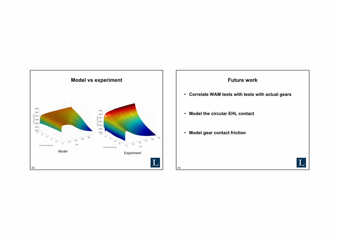
3D friction map
3
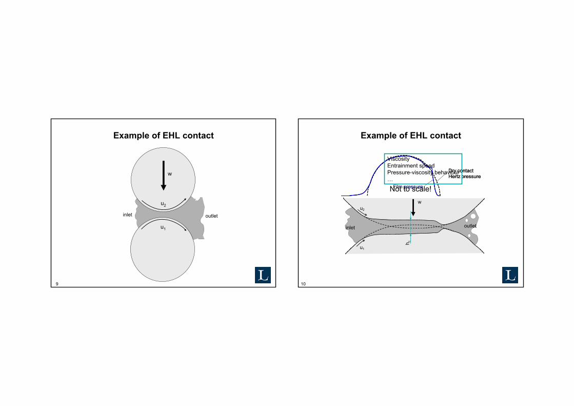
Elasto Hydrodynamic Lubrication (EHL)
4
Elasto Hydrodynamic Lubrication (EHL)
5
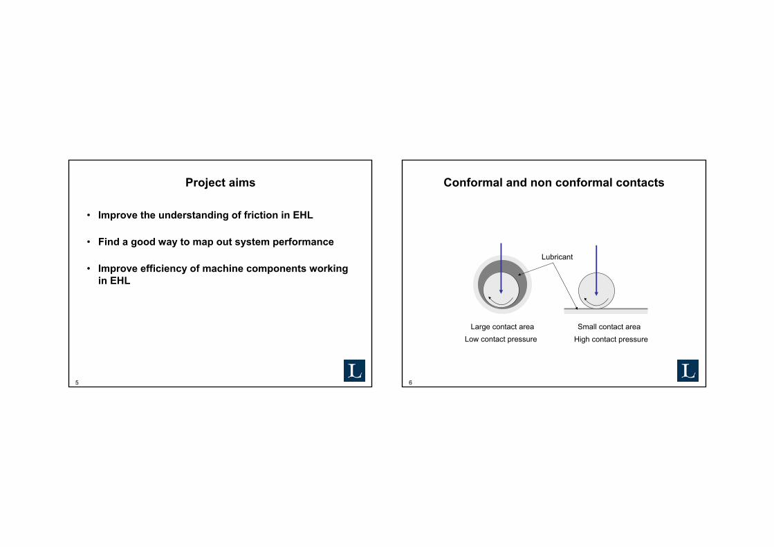
Project aims
• Improve the understanding of friction in EHL
• Find a good way to map out system performance
• Improve efficiency of machine components working in EHL
6
Conformal and non conformal contacts
Lubricant
Small contact areaHigh contact pressure
Large contact areaLow contact pressure
7
Typical contact pressure in rolling element bearings, 1-4 GPa!
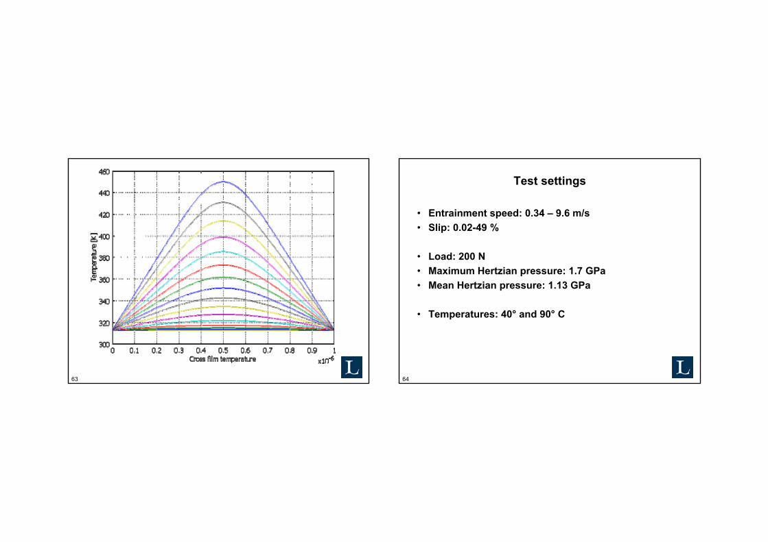
• Load: 200 N• Maximum Hertzian pressure: 1.7 GPa• Mean Hertzian pressure: 1.13 GPa
• Temperatures: 40° and 90° C
65
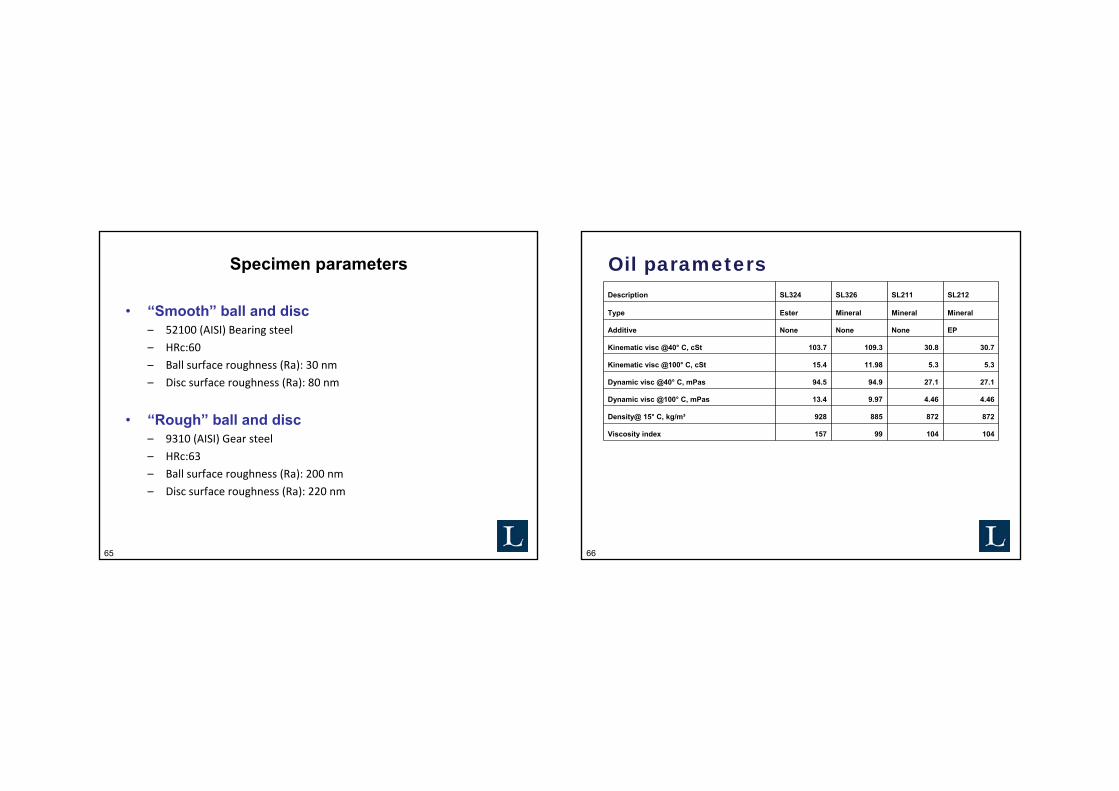
Specimen parameters
• “Smooth” ball and disc– 52100 (AISI) Bearing steel
– HRc:60
– Ball surface roughness (Ra): 30 nm
– Disc surface roughness (Ra): 80 nm
• “Rough” ball and disc– 9310 (AISI) Gear steel
– HRc:63
– Ball surface roughness (Ra): 200 nm
– Disc surface roughness (Ra): 220 nm
66
Oil parametersDescription SL324 SL326 SL211 SL212
Type Ester Mineral Mineral Mineral
Additive None None None EP
Kinematic visc @40° C, cSt 103.7 109.3 30.8 30.7
Kinematic visc @100° C, cSt 15.4 11.98 5.3 5.3
Dynamic visc @40° C, mPas 94.5 94.9 27.1 27.1
Dynamic visc @100° C, mPas 13.4 9.97 4.46 4.46
Density@ 15° C, kg/m³ 928 885 872 872
Viscosity index 157 99 104 104
67
Diamond Like Carbon (DLC) in EHL
In literature• Focus on wear and boundary friction• Mostly pure sliding contacts
New study• Focus on EHL friction in full film lubrication• Rolling and sliding contacts
68
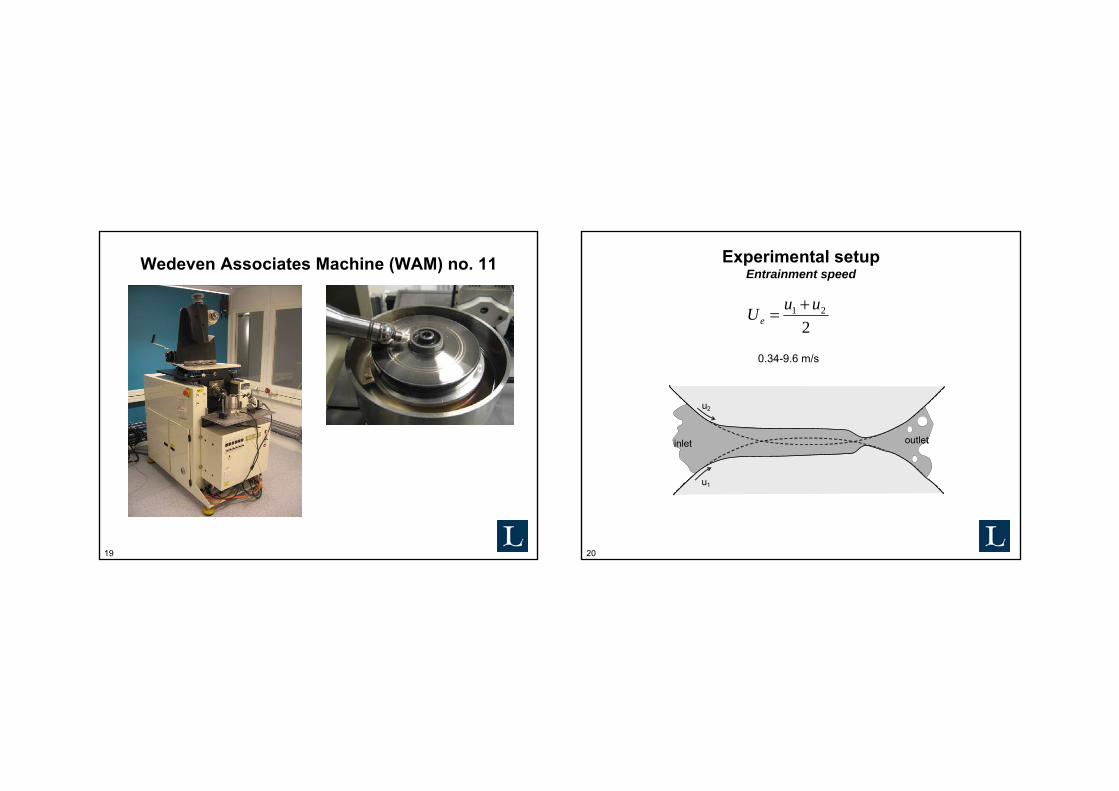
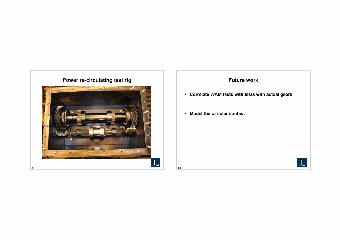
Wedeven Associates Machine (WAM) no. 11
69
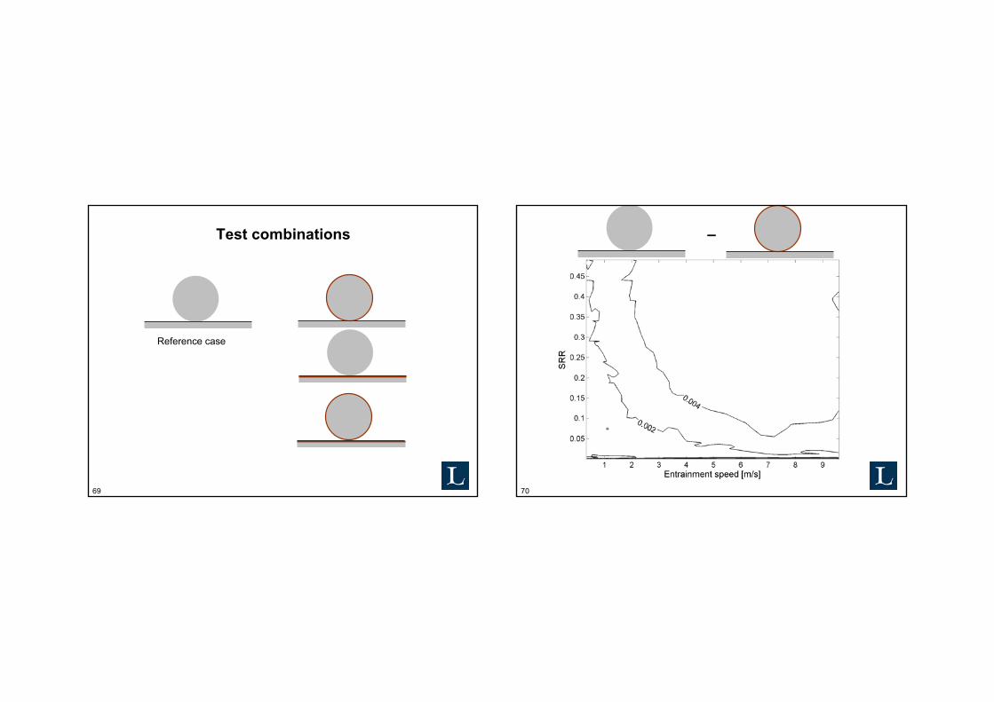
Test combinations
Reference case
70
–
71
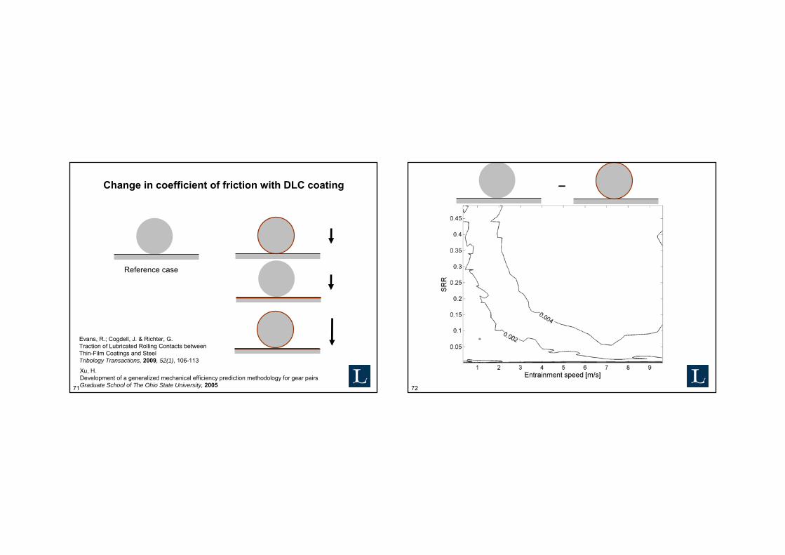
Change in coefficient of friction with DLC coating
Reference case
Xu, H.Development of a generalized mechanical efficiency prediction methodology for gear pairsGraduate School of The Ohio State University, 2005
Evans, R.; Cogdell, J. & Richter, G.Traction of Lubricated Rolling Contacts betweenThin-Film Coatings and SteelTribology Transactions, 2009, 52(1), 106-113
72
–
73
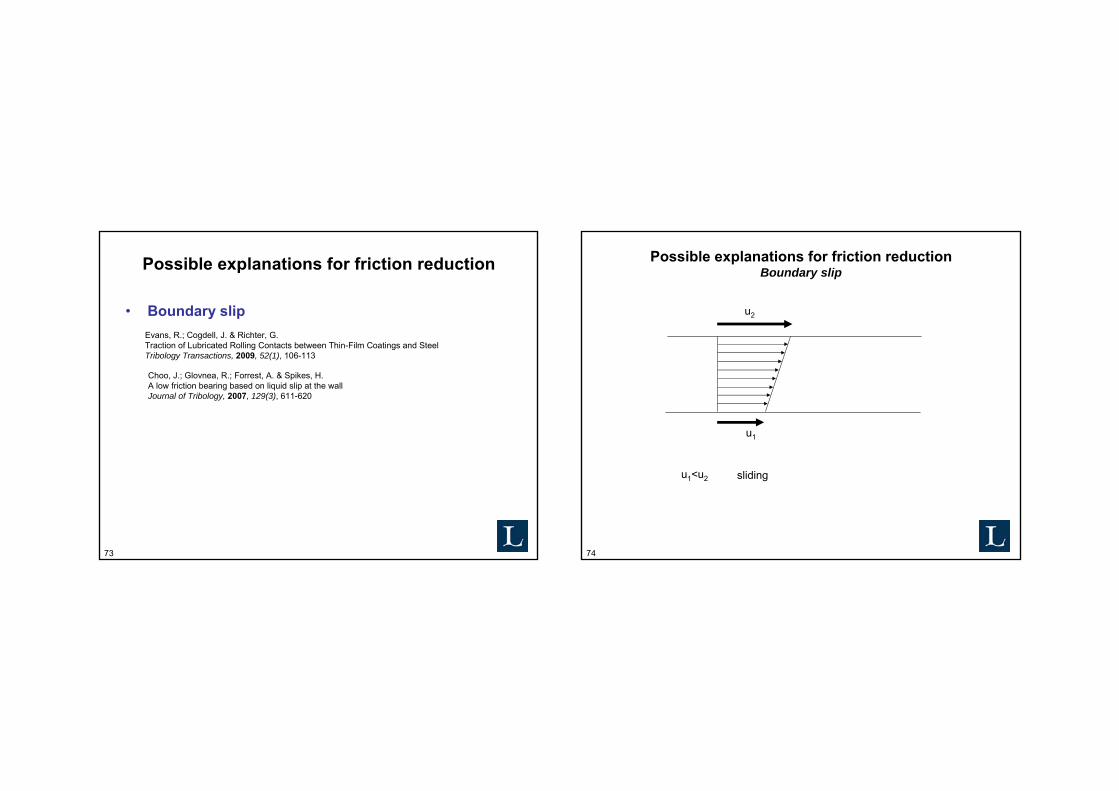
Possible explanations for friction reduction
• Boundary slipEvans, R.; Cogdell, J. & Richter, G.Traction of Lubricated Rolling Contacts between Thin-Film Coatings and SteelTribology Transactions, 2009, 52(1), 106-113
Choo, J.; Glovnea, R.; Forrest, A. & Spikes, H.A low friction bearing based on liquid slip at the wallJournal of Tribology, 2007, 129(3), 611-620
74
Possible explanations for friction reduction Boundary slip
u2
u1
u1<u2 sliding
75
Possible explanations for friction reduction Boundary slip
u2
u1
u1<u2 sliding
Profile for uncoated surface
76
Possible explanations for friction reduction Boundary slip - Limitations
RMS surface roughness of about 1 nm Reduction in friction
RMS surface roughness of about 10 nm No reduction in friction
Combined roughness in present test: > 155 nm
77
Possible explanations for friction reduction
• Thermal effects– Decrease in limiting shear stress
Kim, J.; Yang, H.-S.; Jun, Y. & Kim, K.Interfacial effect on thermal conductivity of diamond-like carbon filmsJournal of Mechanical Science and Technology, 2010, 24(7), 1511-1514
Wojciechowski, K.; Zybala, R. & Mania, R.Application of DLC layers in 3-omega thermal conductivity methodJournal of Achievements in Materials and Manufacturing Engineering, 2009, 37(2), 512-517
81
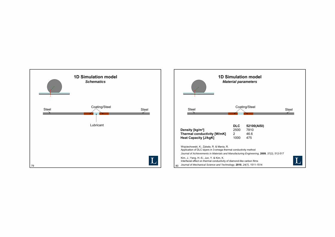
1D Simulation modelFilm thickness
SteelCoating/Steel
Steel
• Hamrock & Dowson central film thickness• Hsu and Lee thermal correction
Hsu, C.-H. & Lee, R.-T.An Efficient Algorithm for Thermal Elastohydrodynamic Lubrication Under Rolling/Sliding Line ContactsJournal of tribology, 1994, 116(4), 762-769
Hamrock, B.Fundamentals of fluid film lubricationMcGraw-Hill, 1994
82
1D Simulation modelBoundary conditions
Bulk temperature Bulk temperature
Heat source
Continuity
83
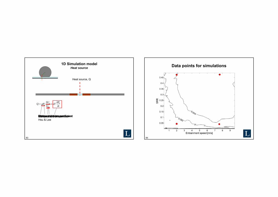
1D Simulation modelHeat source
Heat source, Q
tPT
hSUPQ h
cen
eh ∂
∂+= εμ
Measured friction coefficientCircular Hertzian pressureSRR and entrainment speedHamrock & Dowson Hsu & LeeCompression of lubricant
84
Data points for simulations
85
Effect of DLC coating on oil film temperature increase