Elasto-kinematics design of an innovative compositematerial suspension system
Shuang Xu, Alessandro Ferraris, Andrea Giancarlo Airale, and Massimiliana CarelloMechanical and Aerospace Engineering Department, Politecnico di Torino, C.so Duca degli Abruzzi 24 Turin,
Received: 15 July 2016 – Revised: 26 January 2017 – Accepted: 6 February 2017 – Published: 24 February 2017
Abstract. In this paper, a lightweight suspension system for small urban personal transportation vehicle ispresented. A CFRP (Carbon fiber reinforce polymer) beam spring has been used to efficiently integrate thefunctions of suspension control arm and anti-roll bar. Composites materials were chosen to tailor the requiredbehavior of the beam spring and to reduce the weight. Furthermore, larger space for engine compartment hasbeen provided thanks to the compact arrangement of beam suspension components. This suspension could beinstalled on electric/hybrid vehicles and conventional automobiles.
1 Introduction
The suspension system is very important in an automobile,since it directly affects the handling performance and the ridecomfort. All the driving/braking force and lateral force dur-ing cornering are transferred to the car body from the groundthough the suspension system.
Weight reduction is an important task in the current trendof automobile development. Aluminum alloys were com-monly used to substitute steel, which can obtain a weight re-duction up to 30 % (Fuganti and Cupitò, 2000). However, us-ing aluminum for structural components such as coil springsand anti-roll bars can be very difficult for effectively reduc-ing weight while keeping the same reliability. By introduc-ing composite materials into lightweight design1, engineersalso have the possibility to improve vehicle dynamic perfor-mance. The usage of CFRP has been usually associated withhigh-end racing cars for building their body shell and chassis.For example, Formula 1 cars have achieved around 80 % ofits components made with composite material (Kulshreshtha,2002).
Although not widely used, composite leaf springs can befound in automotive sector and in these cases the compositeleaf spring has the same performance in terms of component
1More than 50 % mass can be reduced using composite material(Beardmore, 1986).
stiffness with an increase of durability as much by five timesand weight reduction of 65 % (Wood, 2014). The compositeleaf spring presented in this paper, is a highly deformable“beam component” made with CFRP integrating the functionof spring, anti-roll bar and control arm. The proposed designsaves space, system weight and complexity.
Due to the architecture chosen, the CFRP works as a com-plaint mechanism (CM; Hao et al., 2016), which has certainstiffness under loading during in working condition. In thisresearch, the CFRP beam spring sustains the load to supportthe vehicle, while the deformation is far beyond the linearrange. For this reasons particular attention has been given tomanufacturing process and the simulation modeling.
2 Suspension topology
A front wheel driven (FWD2) vehicle has been chosen as acase study, which is designed to use McPherson strut suspen-sion on the front axis and SLA suspension on the rear axis.That is the most competitive combination for space saving ofpower train and improved lateral performance of the vehicle
The conventional McPherson suspension is well knownfor its simple design, compact space as well as the largeshock absorber and the heavy “banana shape” lower control
2FWD: Front wheel drive, in this case, the engine is alsomounted on the front axis.
Published by Copernicus Publications.
12 S. Xu et al.: Elasto-kinematics design of an innovative composite material suspension system
Figure 1. Topology comparison. (Upper/lower body and wheel are not count for suspension components).
arm. Since no upper control arm is present, the lateral spaceis larger compared to SLA suspension, which is the main rea-son for front mounted engine arrangement. It usually has thefollowing components:
– Wheel hub
– Upright
– Lower control arm∗
– Shock absorber (strut)
– Coil spring∗
– Antiroll bar∗
– Tie rod
In the purposed architecture, components marked with “*”are made redundant by integrating its function and substi-tuted by a single CFRP beam spring as a shaded block shownin Fig. 1, the rear SLA suspension topology is similar butwith an additional aluminum upper control arm.
Benefits of using a beam suspension solution are that ad-ditional space can be available with no spring (and its seat)presented and the strut can be placed closer to the wheel as-sembly. This can also provide better handling with a smallscrub radius at relative high speed (Milliken and Milliken,1995).
The rear suspension cannot have the same level of spacereduction, but the weight is reduced by component and func-tion integration.
2.1 Beam spring functionality
The most common application of CFRP is weight reductionof the chassis frame and body panels while keeping the same
durability. In this application, CFRP is used to create a de-formable beam spring to substitute the suspension lower con-trol arm, which is virtually divided into three sections by thebushing mounting point on the left and right (Fig. 2).
During the parallel wheel travel (wheels of the same axison both side moves in the same direction vertically), thebeam deforms like a bow, functioning like a normal coilspring. When one wheel is moving vertically in the oppositedirection of the other wheel (known as the opposite wheeltravel) the beam deforms into an “S” shape, working like ananti-roll bar.
To achieve the desired vehicle dynamics performance, thestiffness of the beam under parallel wheel travel and oppositewheel travel are achieved by the correct number of the plyand the stacking sequence that is used during manufacturingof CFRP beam spring.
2.2 Metallic components
Using components such as upper control arm of rear SLAsuspension and some other pieces made of metal (mostly alu-minum alloy) has several reasons. First of all, to simplify themanufacturing process for non-definite components. Being aprototype vehicle, it is important to keep some design spaceand make it possible to implement some modifications ofthe components. Carbon fiber components are optimal whenconsidering weight reduction, but once they have been built,it is very difficult to modify.
Besides, metallic component design procedure is relativelysimple; for carbon reinforced plastics, instead, the static anddynamic loading design is difficult due to its anisotropicstructure. A precise finite element analysis for such compo-nents can be very complex and unreliable. For these reasons,using the metallic components in prototyping phase is morereasonable.
S. Xu et al.: Elasto-kinematics design of an innovative composite material suspension system 13
Figure 2. Unloaded front CFRP beam.
Figure 3. XAM (left), XAM 2.0 (right).
Due to this, nearly all the other components apart fromthe CFRP beam have been made with machined aluminumalloy. For future mass production, some of those compo-nents can be replaced with stamped aluminum sheets or hol-low casted components with optimized structure design, sofurther weight reduction could be achieved (European Alu-minum Association, 2013).
3 Suspension modeling method
The entire development of the prototype virtual model hasbeen performed using MSC ADAMS/Car and Altair Ra-dioss. The multi-body dynamic model has been made inADAMS/Car in order to achieve a good precision on multi-body simulation and modeling. A reference suspension forsetting performance targets has been set-up with conven-tional suspensions (with coil springs) as well.
Altair Radioss has been used to correlate the materialproperties and the design parameters. To verify the stiffnesswith respect to design target after the prototyping of the beamspring, a simple test bench has been used.
The modeling of the CFRP beam suspension has been di-vided into 4 steps:
– Reference suspension modeling
– Rough prediction for beam spring characteristic using“Non-linear” beam tool in ADAMS
– Finite Element Method simulation and correlation withphysical experiments
– “Non-linear” beam calibration with reference to theFEM results
Since it is complicated to start with CFRP beams, a “refer-ence suspension model” with conventional suspensions hasbeen defined in the beginning. MSC ADAMS is the mostcommonly used MBD simulation environment in the indus-try, two previous award-winning vehicles (Fig. 3) with con-ventional suspensions are designed successfully in the past.The experiment data on the test track is well correlated withthe simulation results (Carello et al., 2014, 2012).
The reference suspension has been defined to have±70 mm wheel travel, and an understeering behavior hasbeen chosen to ensure safety. Consequently, the front sus-pension has a −0.4◦ of camber angle variation at maximumstroke and a toe-out of 0.7◦ when the coil spring is fully com-pressed.
Due to the rear suspension design for beam spring, no sig-nificant toe variation has been set. The camber variation forthe reference rear suspension has been set to −2.1◦.
Beam suspension from geometric and kinematic point ofview is identical for the two suspension models (referenceand beam suspension models) as shown in Fig. 4.
14 S. Xu et al.: Elasto-kinematics design of an innovative composite material suspension system
Figure 4. MBD full vehicle model, reference-handling model (left),BEAM Spring suspension vehicle prototype (right).
3.1 Non-linear CFRP beam
In this particular project, the beam has to be mounted trans-versely rather than longitudinally. The study shows in orderto maximize the limit for elastic strain energy storage, thebeam should be designed to have a tapered shape for verti-cal loading along the length (Yu and Kim, 1988). Still, a de-sign with constant thickness along the length has been chosento balance cost and performance, also because the space re-quired for mounting the tapered beam is not available, and itis very difficult to prototype.
The beams have been designed to have two differentshapes for front and rear axle. The beam on the front is de-signed to have an isosceles trapezium shape to have higherlongitudinal stiffness considering driving axle may sustainheavier load on the longitudinal direction during accelera-tion. Another reason is that the mounting system becamemore reliable for constraining the beam movements duringdriving condition as shown in Fig. 5 for front suspensionbeam and its mounting design. The CFRP beam has the shapeof a bow to have a higher constructional strength and curvedto have correct preload.
At the end of both sides, two plates are mounted by threadfasteners, making a “sandwich structure”. The beam is drilledthrough to let the thread fastener pass. On the lower plate,there is another hole left for the spherical joint, which is fur-ther connected with upright.
The bushing housings have been milled from a block of7075 aluminum alloy. To prevent potential damage on thefiber beam (due to high-localized stresses) a layer of elas-tomer has been inserted between the beam and the steel plate.
On the rear axle, the geometry of the beam is differentfrom the front and its shape is similar to a simple rectangularplate with curvature. The curved shape is to ensure the nec-essary preload when the vehicle is assembled and to permitthe right vertical wheel travel same as front.
Comparing with the front McPherson suspension (shockabsorber mounted between the upright and the top mount onthe chassis), the rear SLA suspension shock absorber is usu-ally mounted on the lower suspension control arm.
In Fig. 6, on the metal plate for mounting the upright, apartfrom the two coaxial hole (drilled to fix the upright), there is
Figure 5. Front beam suspension in ADAMS/Car.
another small hole drilled on the vertical surface, for mount-ing the shock absorber, because drilling any more holes onthe CFRP beam is not recommended for its reliability. Therear suspension is chosen to use a “H arm” topology3 toeliminate the need for another linkage for toe control. Theside effect is that the toe variation during suspension strokeis limited.
To recreate the performance of the beam suspension, thetool “non-linear beam” in ADAMS/Car is used, which isshown in Fig. 4. The non-linear beam is defined as a flexi-ble body made with several connected deformable segments,which is an ideal component to present the behavior of beamspring in multi-body dynamics model.
3.2 Parametrization of beam spring
Suspension geometry has been defined using the referencemodel to reach the performance target. To reach the sameperformance after substitution with the beam, several tun-ing and modification of the model may be necessary. Asthe beam is relatively deformable compared to the rigid con-trol arm in conventional solution, kinematic performance forbeam suspension has some variance using the same geometryfrom reference model.
Since CFRP beam springs have been used to substitute thelower control arm, the hardpoints of the reference suspensionneed to be recreated in the CFRP beam spring. Other char-acteristics such as the length, thickness, cross-section shapeand material properties used are very important for calculat-ing the stiffness, damping and weight during simulation withthe “non-linear beam” tool for CFRP beam.
3Such as the rear suspension of Gunnell (2008) Ford Thunder-bird (1992–1996).
S. Xu et al.: Elasto-kinematics design of an innovative composite material suspension system 15
Figure 6. Drilled hole for mounting the shock absorber on rearbeam (1).
To have the expected stiffness for the beam according tothe performance design is very difficult, and for the FEManalysis, an initial geometry for the beam is required. In or-der to integrate the functionality of spring and anti-roll bartogether in the single beam spring, it is difficult to obtain thedesired result by manual “trial and error”, considering hightime consuming computational FEM simulations.
MBD simulation with DoE has been applied to obtain thecorrect design parameters, and the original MBD model wasimproved as the DoE needs parametrized model.
The beam spring has been modeled with simple parame-ters considering the cross section width and thickness (beamspring length is fixed by the overall design of the trackwidth). During the development, it was intended to avoidcross section variation along the lateral direction. Variablethickness of the beam may lead to stress concentration(which increases the probability of delamination) during thedeformation and production complexity will be increased aswell.
It needs to be pointed out that in ADAMS/Car system, thegeometry of the beam cannot be effectively controlled by the“parameter variable”4, and so it is necessary to modify themodel in code level.
Once the material properties5 of CFRP are determinedthrough experimental test, the only aspect could be modi-fied in the design process is the moment of inertia (the cross-section). The non-linear beam component in MBD modelreads the moment of inertia calculated by the parameter vari-
4The geometry can be controlled normally in the environmentof template, but the simulation can only be done in the normal en-vironment.
5The properties used in MBD model include: elastic modulus,shear modulus, Poisson ratio and density. Stacking sequence ofCFRP beam spring is designed in FEM model.
ables using simple formulas, which can be modified to createDoE iterations.
In order to perform the calculation for moment of iner-tia automatically during DoE iterations, additional scripts arenecessary.
Front suspension has a large slot in the center of the beamcomponent (giving space for electric motor and other compo-nents), which is modeled as two separate beam attached witheach other at the beam ending (as shown in Fig. 2). The rearbeam is also divided into two separate part to achieve H-armstructure on rear suspension. In such configuration, the beamcomponents in the model are named as:
– Front suspension front beam(beam_front_nrl/nrr/nrs6_lca_front)
– Front suspension rear beam(beam_front_nrl/nrr/nrs_lca_rear)
– Rear suspension front beam(beam_rear_nrl/nrr/nrs7_lca_front)
Nonlinear beam elements in a single beam are sharingthe same geometry properties8 (thickness and width). Eventhough user can modify the thickness and width by click ondifferent beam segment (beam elements), the beam will actas a single component just using the last input value userconfigured in any individual beam segment.
When writing the script, it is mandatory to use“Adams/view Command”, which is based on concept of“object-variable” and every variable belongs to its parentcomponent. To make the variable accessible to DoE environ-ment, users can choose any segment of a beam component,and reconfigure the variable of “height” (stands for thick-ness) and “width” into “parameter variables”.
8In Adams environment, properties of an object are called“VARIABLE”, more like the “dependent variable” in general math-ematic formula, its value is determined by other input values. “Pa-rameter variables” are user-defined additional “parameters”, morelike the “independent variables”, which give input values to the sys-tem.
16 S. Xu et al.: Elasto-kinematics design of an innovative composite material suspension system
It needs to be pointed out that “variables” in MBD modelcannot be modified DoE iteration, but “parameter variables”can be accessed easily by user using graphic interface orcommand line same as DoE functions. Eight individual pa-rameter variable were created in total (two for each beamcomponent, four beams in total). Changing the variables intoparameter variables makes the beam lose the original sourceof properties, the force calculation is no longer valid. Theforce calculating functions need to be manually redirected tothe new parameter variables that have been modified.
The functions of beam component forces are:
– Ixx
– Iyy
– Izz
– Y_shear_area_ratio
– Z_shear_area_ratio
– Youngs_modulus
– Shear_modulus
– Area_of_cross_section
– Damping_ratio
The above functions can be modified using Adams/viewCommand.
The final step for the script preparation is to create “DoEdesign objective” using the function builder. For this re-search, the beam spring stiffness under different loadingcases (parallel wheel travel/opposite wheel travel) is neededand is calculated using simple “force-displacement” func-tion.
Another function is defined as an additional indicator forbeam spring stiffness: the stiffness linearity. As the experi-ment results show the CFRP beam spring has a certain non-perfect linear stiffness behavior. It tends to increase its stiff-ness when the displacement is increasing. The minimal valueof stiffness appears when the beam is not loaded, similarto a uniform cubic function passing through origin. DoEshows the results only when an objective function is defined,so there is no way to observe the non-linearity without afunction. The non-linearity function is very simple in thiscase, the function calculates the ratio (rnl = kfs/khs) betweenthe mean stiffness within 1/2 the total wheel displacement(khs: ±35 mm) and the stiffness at the maximum stroke (kfs:±70 mm).
DoE simulation has to use only one simulation script forevery iteration. In this case, the script need to perform par-allel wheel travel and opposite wheel travel simulation in asingle simulation run. The DoE script is written to performfirst parallel wheel travel, then return the wheel back to itsoriginal position, at last the suspension will be asked to per-form an opposite wheel travel.
Table 1. General set-up of vehicle model.
Property Unit Value
Loaded weight at SD A∗ kg 785Weight repartition (front/rear) – 45/55Maximum loaded weight kg 870Wheel base/ front track/rear track mm 1912/1170/1170Ground clearance at SD A mm 140Hcg at SD A mm 350Suspension stroke mm ±70Minimum ground clearance at SD A mm 120Tire – 95/80R16Powertrain layout – FF
∗ One driver (75 kg) and one luggage (10 kg) are included.
The design objective functions are written as “time depen-dent” functions. For example, wheel center force (FCW) forcalculating the khs is read in four different moments usingAdams/View function “VALAT (array,array,REAL)9”:
– FCW at −35 mm for parallel wheel travel10
– FCW at +35 mm for parallel wheel travel
– FCW at −35 mm for opposite wheel travel
– FCW at +35 mm for opposite wheel travel
The other functions are written in the same way as for kfs andrnl.
4 Simulation results
The research is processed through reference model study tothe beam suspension mode; the general set-up of the vehi-cle model is shown in Table 1. The kinematic characteristicsand dynamic behavior has been defined through the simula-tion trails referred with specific performance targets for rid-ing comfort and safety
DoE simulation is performed only to identify the geome-try size of beam components in this article. The kinematicsimulation is geometry-dependent, while tuning is based onsuspension performance targets and CAD design space. Dy-namic simulation is more component-dependent, as the stiff-ness and damping of elastic components can significantlychange the dynamic response.
9The function VALAT is a linear interpolation for arrays, themeasurement results are arrays for example.
10Adams/View function is written as: VALAT (ANALY-SIS.left_hub_forces.TIME,ANALYSIS.left_hub_forces.normal,TIME). “TIME” is the real number for the moment when wheelhub reaches −35 mm wheel travel.
S. Xu et al.: Elasto-kinematics design of an innovative composite material suspension system 17
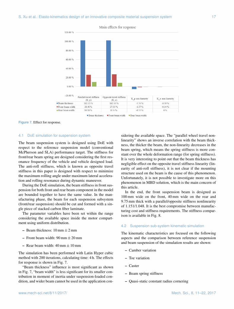
Figure 7. Effect for response.
4.1 DoE simulation for suspension system
The beam suspension system is designed using DoE withrespect to the reference suspension model (conventionalMcPherson and SLA) performance target. The stiffness forfront/rear beam spring are designed considering the first res-onance frequency of the vehicle and vehicle designed load.The anti-roll stiffness, which is known as opposite travelstiffness in this paper is designed with respect to minimizethe maximum rolling angle under maximum lateral accelera-tion and rolling resonance during dynamic maneuver.
During the DoE simulation, the beam stiffness in front sus-pension for both front and rear beam component in the modelare bounded together to have the same value. In the man-ufacturing phase, the beam for each suspension subsystem(front/rear suspension) should be cut and formed with a sin-gle piece of stacked carbon fiber laminate.
The parameter variables have been set within the rangeconsidering the available space inside the motor compart-ment using uniform distribution.
– Beam thickness: 10 mm± 2 mm
– Front beam width: 90 mm± 20 mm
– Rear beam width: 40 mm± 10 mm
The simulation has been performed with Latin Hyper cubicmethod with 200 iterations, calculating time: 4 h. The effectsfor response is shown in Fig. 7.
“Beam thickness” influence is most significant as shownin Fig. 7, “beam width” is less significant for its smaller con-tribution in moment of inertia under suspension-loaded con-dition, and wider beam cannot be used in the application con-
sidering the available space. The “parallel wheel travel non-linearity” shows an inverse correlation with the beam thick-ness, the thicker the beam, the non-linearity decreases in thebeam spring, which means the spring stiffness is more con-stant over the whole deformation range (for spring stiffness).It is very interesting to point out that the beam thickness hasnegligible effect on the opposite travel stiffness linearity (lin-earity of anti-roll stiffness), it is not clear if the mountingstructure used on the beam is the cause of this phenomenon.Unfortunately, it is not possible to investigate more on thisphenomenon in MBD solution, which is the main concern ofthis article.
In the end, the front suspension beam is designed as100 mm wide on the front, 40 mm wide on the rear and9.75 mm thick with a parallel/opposite stiffness nonlinearityof 1.151/1.048. It is the best compromise between manufac-turing cost and stiffness requirements. The stiffness compar-ison is available in Fig. 8.
4.2 Suspension sub-system kinematic simulation
The kinematic characteristics are focused on the followingaspects and the comparison between reference suspensionand beam suspension of the simulation results are shown:
18 S. Xu et al.: Elasto-kinematics design of an innovative composite material suspension system
Figure 8. Beam spring stiffness tuning (compression stiffness and anti-roll stiffness).
Figure 9. Front suspension kinematics.
Simulations have been done for both reference model andbeam model, using the common parallel wheel travel on frontand rear suspension. According to the common experienceof chassis design for passenger cars (Gunnell, 2008), the ex-pected performance has the following values in Table 2.
After the reference model has been developed, the beammodel is set-up with all the coordinates of hardpoints fromreference model, afterwards the tuning of beam model hasbeen done to fit the performance of the reference model. Thecomparisons of results are shown in the Fig. 9 for the frontsuspension and Fig. 10 for rear suspension.
As it can be seen, the kinematic characteristics are per-fectly reproduced for the beam suspension, such as camber,kingpin, toe-in/out and caster angle variations11.
Beam spring stiffness has been carefully tuned with re-spect to FEM analysis. The correlation for the stiffness hasbeen compromised12 for the reason of manufacturing cost.
11Correlation factor is more than 99 % between the referencecurve and beam suspension result, using “Pearson correlationmethod” (Pearson, 1985)
12In order to keep the riding height under different loading con-dition respect to the reference model, the beam spring stiffness hasbeen set as the primary target, while the anti-roll stiffness is com-promised.
S. Xu et al.: Elasto-kinematics design of an innovative composite material suspension system 19
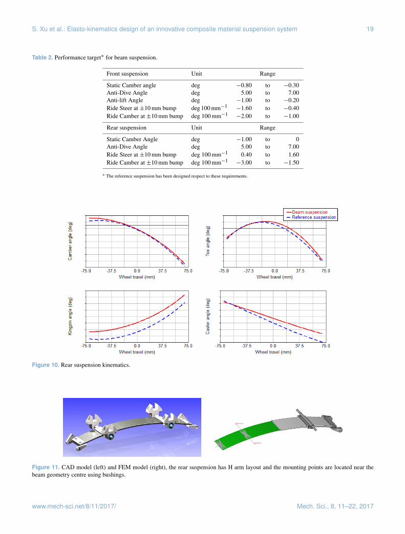
Table 2. Performance target∗ for beam suspension.
Front suspension Unit Range
Static Camber angle deg −0.80 to −0.30Anti-Dive Angle deg 5.00 to 7.00Anti-lift Angle deg −1.00 to −0.20Ride Steer at ±10 mm bump deg 100 mm−1
−1.60 to −0.40Ride Camber at ±10 mm bump deg 100 mm−1
−2.00 to −1.00
Rear suspension Unit Range
Static Camber Angle deg −1.00 to 0Anti-Dive Angle deg 5.00 to 7.00Ride Steer at ±10 mm bump deg 100 mm−1 0.40 to 1.60Ride Camber at ±10 mm bump deg 100 mm−1
−3.00 to −1.50
∗ The reference suspension has been designed respect to these requirements.
Figure 10. Rear suspension kinematics.
Figure 11. CAD model (left) and FEM model (right), the rear suspension has H arm layout and the mounting points are located near thebeam geometry centre using bushings.
20 S. Xu et al.: Elasto-kinematics design of an innovative composite material suspension system
Table 3. Swept-sine steering simulation result comparison.
Yaw rate – Steering anglea Unit Reference model Beam model
Steady Gain s−1 0.40 0.43Gain at 0.5 Hz s−1 0.43 0.52Delay at 0.5 Hz s 0.029 0.029DFb – 1.20 1.23
Roll angle – Lateral acceleration Unit Reference model Beam model
Steady Gain deg g−1 4.01 4.76Gain at 0.5 Hz deg g−1 4.06 4.06DF – 1.74 1.05
Slide slip angle – Steering angle Unit Reference model Beam model
Steady Gain – 0.044 0.064Gain at 0.5 Hz – 0.047 0.073Delay at 0.5 Hz s 0.81 0.80DF – 1.07 1.03
a INPUT – OUTPUT; b Damping factor=Gain(max)/Gain(steady).
The beam has been designed to have uniform thickness.Complex lamination will increase the complexity and uncer-tainty during manufacturing.
The rear suspension has been designed using the “H arm”,the toe angle cannot be efficiently tuned as shown in Fig. 10.
The skid pad simulation13 showed a good correlation forunder-steering ratio, 37.19 deg g−1 for reference model and36.26 deg g−1 for beam model.
4.3 Dynamic simulation-swept sine steering
The swept sine steering is very important for understand-ing the full vehicle steering response on frequency domain(Fisher, 2011). The initial speed for the vehicle has been cho-sen as 80 km h−1 and simulation has been performed cover-ing the frequency range 0.05 to 5 Hz. Some representative re-sults are shown in Table 3, the correlation between the beamsuspension and reference suspension is good.
At this moment, it is clear that the beam spring suspen-sion proposed can reproduce with a good agreement the per-formance of the reference suspension (conventional type) interms of global handling. Which means it is possible to sub-stitute the conventional suspension (coil spring and metalliccontrol arms) with CFRP beam spring suspension for stan-dard passenger vehicles without changing the handling per-formance of the existing ones.
13Skid pad test with a radius of 40 m and simulate the vehiclefrom steady until reaching 1 g lateral acceleration.
Figure 12. Closed mould filled with Carbon fibre ply and resin.
S. Xu et al.: Elasto-kinematics design of an innovative composite material suspension system 21
Table 4. Improvements respect to conventional aluminum made suspension system.
Improvements Unit Value Difference
Front suspension weight reduction kg −10.2 −29.1 %Rear suspension weight reduction kg −10.7 −26.8 %Wheel to strut distance at front suspension mm −17 −34 %Wheel to strut distance at rear suspension mm −22 −44 %Strut mounting height at front suspension mm −11 −7.4 %Front spring seat plate – Removed, no spring needed −100 %Rear spring seat plate – Removed, no spring needed −100 %
Figure 14. Comparison between FEM analysis result, test bench experimental data and Vehicle Dynamic design target.
5 Building the Beam suspension
Using the approved vehicle-dynamics simulation results, thecharacteristics of the beam components were approximatelydefined and the first component CAD was created.
FEM analysis has been done to obtain the optimum plysequence (55 layers) and orientation (Fig. 11).
The beam has been produced completely manually, by us-ing a special vacuum bag technology and autoclave process(Uddin, 2013) to ensure the correct polymerization withoutany defects in the melt resin. The mold is floating with thecarbon fiber to give the better surface finishing and ensurethe uniform pressure on the whole piece (shown in Fig. 12).
After cleaning the flanges and drilling for addition com-ponents (joint housing), the component is mounted on thechassis prototype.
A simple test bench for evaluating the beam spring stiff-ness has been made (Fig. 13), with five strain gaugesmounted on the spring and weight loaded on the bushingmountings. In Fig. 14, the final Force-Displacement corre-lation for the beam spring is shown. The displacement startsfrom −90 mm to generate correct preload at normal loadedposition. The wheel travel will be limited with the rebound-stop integrated in the shock absorber, in order to guaran-tee the negative wheel travel won’t exceed the lower limit(−70 mm).
The experimental data shows that the beam spring has suc-cessfully manufactured with respect to the design target forthe beam suspension model.
6 Conclusion
In this research, an innovative construction of suspensionsystem has been developed. Using the CFRP beam, the func-tion of lower control arm, coil spring and anti-roll bar hasbeen integrated into a single lightweight composite compo-nent. The solution provides new possibilities for saving spaceand weight reduction (comparison data with conventional ve-hicle on the market is presented in Table 4).
For front suspension tower, the spring plate has been re-moved since there is no coil spring present, which benefitsthe frontal vehicle part design in styling smoother curvedsurface. When using McPherson suspension on the front, thecoil spring is usually placed over the tire to make the strutclose to the wheel (decrease scrub radius while keep the king-pin more vertical), the mounting point at suspension tower isvery high to fit the coil spring preloaded length. Using CFRPbeam suspension can completely solve this issue, the suspen-sion tower can be as low as the shock absorber stroke withadditional space for bump stop, the mounting point is low-ered more than 10 mm in this case.
Weight reduction is the main benefit for using CFRP beamsuspension. More than 25 % weight is reduced14 comparedto the conventional suspension arm, coil spring and antirollbar with their mountings.
14The suspension beam with mounting weighs less than 5 kg forone axle.
22 S. Xu et al.: Elasto-kinematics design of an innovative composite material suspension system
MBD model has been developed with reference to the per-formance target. FEM analysis using exact material propertywas done to predict the component behavior and to designthe CAD details for production.
For the future development, the study will be focused onthe riding comfort, considering the vibration filtering, thenoise proofing and impact smoothing while driving on un-even surface conditions. Also complex lamination designwill be studied to improve the correlation with respect tothe conventional suspension. Modeling compliant modulesor joints (Li and Hao, 2017) in the mounting system for beamspring will be furtherly studied.
The DoE method provide an effective way to find the as-pect that is more significantly changing the behavior of thebeam spring. The phenomenon of beam thickness effectingnon-linearity of anti-roll stiffness should be studied furthermore.
Production process design will be done later on consid-ering mass production method like RTM and compressionmolding.
7 Data availability
For the reason of this project is subordinate to Fiat ChryslerAutomobiles Group, all the detailed data hidden in graphsare confidential and not for public access.
Author contributions. Massimiliana Carello carried out theCFRP beam concept and designed the suspension. Andrea Airaleperformed the composite material characterization, analysis andproduction process study. Shuang Xu made the MBD model andcompleted the suspension fine-tuning. Alessandro Ferraris is incharge of DoE model setting and results analysis.
Competing interests. The authors declare that they have no con-flict of interest.
Acknowledgements. This work was supported by the lab-oratory of Innovative Electric and Hybrid Vehicle DIMEAS– Politecnico di Torino cooperating with BEOND Spin Off(http://www.beondrive.it) and FCA Group.
Edited by: G. HaoReviewed by: two anonymous referees
References
Beardmore, P.: Composite structures for automobiles, Compos.Struct., 5, 163–176, 1986.
Carello, M., Filippo, N., and D’Ippolito, R.: Performance optimiza-tion for the XAM hybrid electric vehicle prototype, SAE Inter-national Conference, 24–26 April 2012, doi:10.4271/2012-01-0773, Detroit, 2012.
Carello, M., Airale, A., Ferraris, A., and Messana, A.: XAM 2.0:from student competition to professional challenge, Computer-Aided Design and Applications, Taylor & Francis, 11, 61–67,doi:10.1080/16864360.2014.914412, 2014.
Fisher, D.: Handbook of driving simulation for engineering,medicine, and psychology, CRC Press, Boca Raton, 2011.
Fuganti, A. and Cupitò, G.: Thixoforming of aluminum alloy forweight saving of a suspension steering knuckle, Metallurgicalscience and technology, Vol. 18, available at: http://www.gruppofrattura.it/ors/index.php/MST/article/viewFile/1058/1011(last access: 20 February 2017), 2000.
Gunnell, J.: Standard catalog of Ford, 4th Edn., KP, Iola, Wis., 2008.Hao, G., Yu, J., and Li, H.: A Brief Review on Nonlinear Modelling
Methods and Applications of Compliant Mechanisms, Frontiersof Mechanical Engineering, 11, 119–128, 2016.


![An image-based method for modeling the elasto-plastic ... · microstructure. Extensions of the Taylor model to elasto-plastic [4], visco-plastic [5], and finite elasto-viscoplastic](https://static.documents.pub/doc/80x56/5f1d0763daf4b82b9b0a0a49/an-image-based-method-for-modeling-the-elasto-plastic-microstructure-extensions.jpg)


