26
LTE 3G Long Term Evolution Dr. Erik Dahlman Expert Radio Access Technologies Ericsson Research
LTE
3G Long Term Evolution
Dr. Erik Dahlman
Expert Radio Access Technologies
Ericsson Research

© Ericsson AB 2007 2007-03-272
WCDMA
2005/6 2009/102003/4 2007/8 2011/12
HSPA
HSPA evolution
• To further boost 3G Mobile Broadband
• To provide a smooth transition to
4G radio access (IMT-Advanced)
3G Long Term Evolution
3G LTE
• Expansion to wider bandwidth
• New radio access
• Both paired and unpaired spectrum

© Ericsson AB 2007 2007-03-273
3G LTE – Requirements and targets
� Defined in 3GPP TR25.913
�� Very high data ratesVery high data rates– Peak data rates: More than 100 Mbps (downlink) / More than 50 Mbps (uplink)
– Improved cell-edge user throughput
�� Very low latencyVery low latency– Less than 10 ms (User-plane RAN RTT)
– Less than 50 ms (Control-plane dormant-to-active transition)
�� Very high spectral efficiencyVery high spectral efficiency
�� Spectrum flexibilitySpectrum flexibility– Deployable in a wide-range of spectrum allocations of different sizes
– Both paired and unpaired spectrum
�� CostCost--effective migration from current 3G systemseffective migration from current 3G systems

© Ericsson AB 2007 2007-03-274
3G LTE – 3GPP time line
� SAE (System Architecture Evolution) in parallel to LTE
December 2004
• Start ot LTE Study Item
• LTE requirements and
targets in TR25.913
June 2006
• Close of LTE Study Item
• Start of LTE Work Item
September 2007• Finalization of LTE
Stage 3 specification
March 2006• Approval of LTE
Stage 2 specification
November 2005• Decision on basic LTE radio access
• Downlink: OFDM
• Uplink: SC-FDMA

© Ericsson AB 2007 2007-03-275
LTE/SAE – Overall Architecture
EPC
EPC: Evolved Packet Core
MME: Mobility Management Entity
LTA RAN
MME and SAE GW two separate nodes
with open interface in between
(S1 C-plane / S1 U-plane)

© Ericsson AB 2007 2007-03-276
SAE/LTE – Overall architecture
S11
S10
S1 UP
X2
S1 CP
S3
S4
Iu CPGb
GSM WCDMA/HSPA
Iu UP
BSC RNC
BTS NodeB
Non-3GPP access
S2a/b
PCRF
S7
LTE
MME
SGi
(SGi)HLR/HSS
Gr S6
SAE GW
eNode BeNode B
Internet,
Operator Service etc.
SGSN

© Ericsson AB 2007 2007-03-277
NAS
RRC PDCP
RLC
MAC
Control-Plane User-Plane
EPC
eNB
E-UTRAN
Layer 1
SAE GWMME
LTE/SAE – Protocol Architecture
Layer 2
Layer 3

© Ericsson AB 2007 2007-03-278
3G LTE – Key radio-access features
� Spectrum flexibility– Flexible bandwidth
– Duplex flexibility
� Advanced antenna solutions– Diversity
– Beam-forming– Multi-layer transmission (MIMO)
� New radio access– Downlink: OFDM
– Uplink: SC-FDMA
20 MHz1.25 MHz
SC-FDMA
OFDMA
TXTXTXTX

© Ericsson AB 2007 2007-03-279
3G LTE – Spectrum flexibility
� Allow for operation in a wide range of different spectrum– Current and future 3G spectrum (2 GHs, 2.6 GHz, …)
– Migration of 2G spectrum (e.g. 900 MHz)
– Re-farming of other spectrum, e.g. UHF bands
� Uncertain size of future spectrum assignments
� Efficient operation in differently-sized spectrum allocations– Up to 20 MHz to enable very high data rates
– Less than 5 MHz to enable smooth spectrum migration
Need for flexible transmission bandwidth
20 MHz5 MHz< 5 MHz

© Ericsson AB 2007 2007-03-2710
3G LTE – Bandwidth flexibility
� LTE physical layer supports any bandwidth from ∼1.25 MHz
to well beyond 20 MHz in steps of ∼200 kHz (one ”Resource Block”)
Minimum BW ~1.25 MHz (6 RB)
Maximum BW >20 MHz
All LTE terminals must support the maximum bandwidth (up to 20 MHz)
� RF complexity/requirements limit set of bandwidths actually supported– e.g. 1.25 MHz, 1.8 MHz, 5 MHz, 10 MHz, 20 MHz
� ... but relatively straighforward to extend to addtional bandwidths
e.g. to match new spectrum assignments

© Ericsson AB 2007 2007-03-2711
3G LTE – Duplex arrangement
� FDD: Simultaneous downlink/uplink transmission in separate frequency bands– Paired spectrum requried
– Used in all commercial cellular systems
� TDD: Non-overlapping downlink/uplink transmisson in the same frequency band– Possibility for deployment in single (unpaired) spectrum
– Need for tight inter-cell synchronization/coordination
– Reduced coverage due to non-continuous transmission (duty cycle < 1)
�� FDD preferred FDD preferred ifif paired spectrum availablepaired spectrum available
�� TDD as complement to support deployment in unpaired spectrumTDD as complement to support deployment in unpaired spectrum
� Maximum FDD/TDD commonality to ensure TDD terminal availability
fDL/UL
fUL
fDL
FDD TDD

© Ericsson AB 2007 2007-03-2712
3G LTE – Downlink radio access
�� AAdaptive daptive MMultiulti--LLayer OFDMayer OFDM
� Adaptive to channel conditions and spectrum scenarios
– Time and frequency-domain channel adaptation
– Multiple frequency bands, flexible bandwidth, duplex flexibility, …
� Multi-layer transmission to provide very high data rates
and high spectrum efficiency
� OFDM for robust broadband transmission, for lower-complexity multi-
layer transmission, and to enable frequency-domain channel adaptation
Multi-layer transmission
OFDM
time
frequency
TXTXMultiple layers

© Ericsson AB 2007 2007-03-2713
Frequency-domain channel adaptation
� Select user and data rate based on instantaneous channel quality
� Scheduling/adaptation in time-domain already for HSPA data1
data2
data3
data4
TimeFrequency
User #1 scheduled
User #2 scheduled
1 ms
180 kHz
Time-frequency
fading, user #1
Time-frequency
fading, user #2
LTE: Additional scheduling/adaptation in
the frequency domain
LTE scheduling/adaptation on a
1 ms ×××× 180 kHz basis(one ”Resource Block”)
Channel-dependent
scheduling Link adaptation
Both for downlink and uplink
© Ericsson AB 2007 2007-03-2714
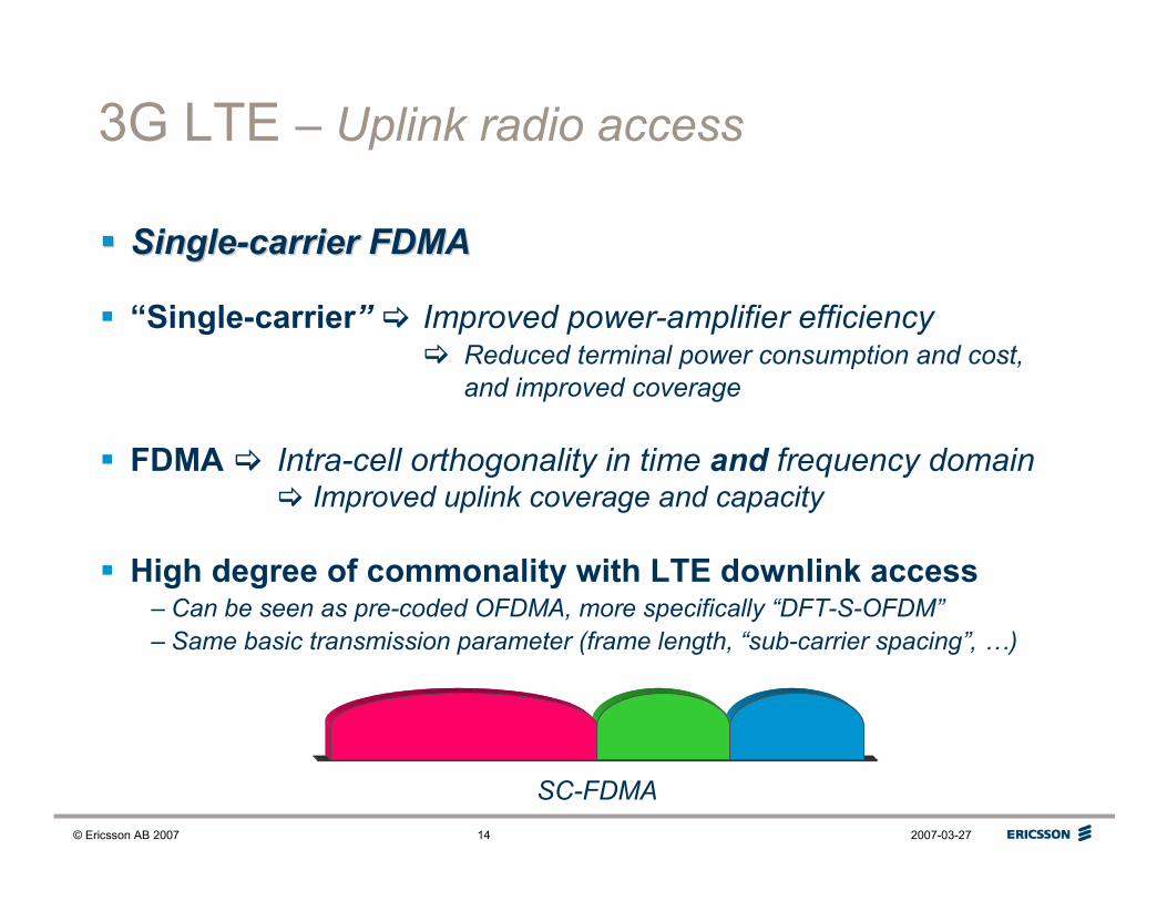
3G LTE – Uplink radio access
�� SingleSingle--carrier FDMAcarrier FDMA
� “Single-carrier”� Improved power-amplifier efficiency� Reduced terminal power consumption and cost,
and improved coverage
� FDMA � Intra-cell orthogonality in time and frequency domain� Improved uplink coverage and capacity
� High degree of commonality with LTE downlink access– Can be seen as pre-coded OFDMA, more specifically “DFT-S-OFDM”
– Same basic transmission parameter (frame length, “sub-carrier spacing”, …)
SC-FDMA

© Ericsson AB 2007 2007-03-2715
Time/frequency-domain orthogonality
time
frequency
Only time-domain orthogonality• Time Division Multiple Access (TDMA)
• Entire bandwidth assigned to one user at a time
� High peak data rates
• Potentially in-efficient for small available
payloads and power-limited user terminals
time
frequency
Additional frequency-domain orthogonality• Frequency Division Multiple Access (FDMA)
• Overall bandwidth can be shared by multiple users
• Efficient support for small payloads
and power-limited user terminals
• Variable instantaneous transmit bandwidth

© Ericsson AB 2007 2007-03-2716
Why single-carrier transmission ?
� OFDM has good performance for broadband communication
due to inherent robustness to radio-channel time dispersion
� ... but also suffers from well-known drawbacks such as– High peak-to-average power ratio � Power-amplifier in-efficiency
– Sensitivity to frequency errors
– Robustness to time dispersion can also be achieved with single-carrier
transmission together with receiver-side frequency-domain equalization
� Downlink: – Power-amplifier efficiency less critical at base-station side
– Avoid excessive user-terminal receiver complexity
� Uplink:
– High power-amplifier complexity is critical in terms of
terminal cost and power consumption, and uplink coverage
– Receiver complexity less critical at base-station side
�������� OFDMOFDM
�������� SingleSingle--carriercarrier
orSC-FDMAOFDM

© Ericsson AB 2007 2007-03-2717
SC-FDMA vs. OFDM?
� Ignoring power-amplifier limitations OFDM has slight advantage
� Assuming realistic power amplifier, single-carrier transmission has
advantage especially in case of larger inter-site distance
�Single-carrier transmission preferred due to coverage advantage
500 1000 1500 2000 25000.8
0.9
1
1.1
1.2
1.3
1.4
1.5
1.6
1.7
1.8
inter-site distance [m]
relative throughput gain: SC vs. OFDM
OFDM, 4 dB pbo (60% load)OFDM, 2 dB pbo (60% load)
OFDM, 0 dB pbo (60% load)
Relative throughput
Single-carrier vs. OFDM
© Ericsson AB 2007 2007-03-2718
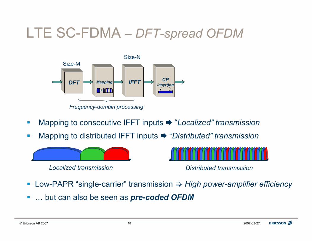
LTE SC-FDMA – DFT-spread OFDM
� Mapping to consecutive IFFT inputs � “Localized” transmission
� Mapping to distributed IFFT inputs � “Distributed” transmission
IFFTCP
insertion
Size-N
Localized transmission Distributed transmission
� Low-PAPR “single-carrier” transmission � High power-amplifier efficiency
� … but can also be seen as pre-coded OFDM
MappingDFT
Size-M
Frequency-domain processing

© Ericsson AB 2007 2007-03-2719
Interference coordination(“adaptive reuse”, “soft reuse”, …)
� High data rates in limited spectrum allocations– Entire spectrum must be available in each cell
� One-cell frequency reuse
Reduced Tx power
� Reduced inter-cell interference with frequency reuse > 1– Improved cell-edge SIR � Higher cell-edge data rates
� Adaptive reuse– Cell-center users: Reuse = 1
– Cell-edge users: Reuse > 1
� Relies on access to frequency domain� Applicable for both downlink OFDM and uplink SC-FDMA

© Ericsson AB 2007 2007-03-2720
3GPP LTE – Multi-antenna solutions
� LTE targets extreme performance in terms of – Capacity
– Coverage
– Peak data rates
Advanced multi-antenna solutions is thethe key tool to to achieve this
� Different antenna solutions needed for different scenarios/targets– High peak data rates � Multi-layer transmission
– Good coverage � Beam-forming
– High capacity � Beam forming (and multi-layer transmission)
TXTX
MultiMulti--layer transmissionlayer transmission
((““MIMOMIMO””))
TXTX
BeamBeam--formingforming
© Ericsson AB 2007 2007-03-2721
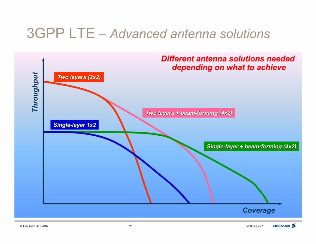
3GPP LTE – Advanced antenna solutions
Two layers + beamTwo layers + beam--forming (4x2)forming (4x2)
Two layers (2x2)Two layers (2x2)
SingleSingle--layer + beamlayer + beam--forming (4x2)forming (4x2)
SingleSingle--layer 1x2layer 1x2
Coverage
Throughput
Different antenna solutions needed Different antenna solutions needed depending on what to achievedepending on what to achieve

© Ericsson AB 2007 2007-03-2722
3G LTE – Multi-antenna solutions
� Multiple RX antennas: Two-antenna RX diversity mandatory
at the mobile terminal
� Downlink transmit diversity: SFBC (Space-Frequency Block Coding)
� Code-book-based pre-coding � Spatial multiplexing
– 2×2, 2×4, 4×4
– Rank adaptation � Single-layer beam-forming as special case
TXTX
MultiMulti--layer transmissionlayer transmission
((““MIMOMIMO””))
TXTX
BeamBeam--formingforming

© Ericsson AB 2007 2007-03-2723
3G LTE – Multicast/Broadcast
� MBMS – Multimedia Broadcast/Multicast Service
� OFDM allows for high-efficient MBSFN operation
– Multicast/Broadcast Single-Frequency Networking
– Identical transmissions from set of tightly synchronized cells
– Increased received power and reduced interference
��Substantial boost of MBMS system throughputSubstantial boost of MBMS system throughput
� LTE allows for multicast/broadcast and unicast on the same carrier
as well as dedicated multicast/broadcast carrier

© Ericsson AB 2007 2007-03-2724
HSPA and LTE – Data rate capabilites
10 Mbps
20 Mbps
50 Mbps
100 Mbps
200 Mbps
HSPA 14 Mbps
HSPA
evolution42 Mbps
5 MHz 20 MHz
LTE >250 Mbps
LTE >65 Mbps

© Ericsson AB 2007 2007-03-2725
To learn more …