WORKING DRAFT IN PROGRESS Chapter 3 302 June 2013 4 GASIFICATION This chapter is newly drafted based partially on the information from the prvious LCP BREF, on collected data for the BREF review, and on the drafting work carried out by the subgroup on gasification / liquefaction / pyrolisis. The gasification technologies covered within this BREF document include techniques linked to combustion processes and with a minimum total rated thermal input of 20 MW th (i.e. “fuel pre- treatment technology” for LCP). Whereas a number of different gasification technologies are included in this definition, at the time of writing (2013), no dedicated pyrolysis or liquefaction technologies have been idengified, with a size that is relevant for the purpose of this document. Therefore, the technologies described in this document focuses on gasification processes mainly. Gasification is a partial oxidation process whereby a carbon source such as coal, petcoke, heavy oil, biomass, heavy residues from crude oil refinery process, or RDF, by means of heat with a limited/controlled supply of oxygen, is converted into carbon monoxide (CO) and hydrogen (H 2 ), plus carbon dioxide (CO 2 ) and possibly hydrocarbon molecules such as methane (CH 4 ), and tar. This mix of gases is known as ‘producer gas’ or ‘synthesis gas’ (syngas); the precise characteristics of the gas will depend on the gasification parameters, such as temperature, the type of feedstock to the gasification process, or the oxidiser used. The oxidiser may be air, in which case the syngas will also contain nitrogen (N 2 ), or steam or oxygen. The syngas can be used in many different ways, e.g. to produce power, steam, hydrogen, and basic chemicals, such as methanol and ammonia. Gasification is an efficient means of converting low-value fuels and residuals into a syngas, as it can be applied to a variety of feedstocks: fossil fuels such as coal or oil, biomass (such as wood, agricultural waste or various crops), manure, asphalt, sewage sludge, plastics, and municipal solid waste. In addition, the high-temperature process refines out corrosive ash elements, such as chloride and potassium, allowing clean gas production from otherwise problematic fuels. A number of factors contribute to a growing interest in gasification. The product and feedstock flexibilities are two key reasons for the popularity of gasification in a market characterised by volatile oil and natural gas prices. Furthermore, using the syngas is potentially more efficient than direct combustion of the original fuel because it can be combusted at higher temperatures or even in fuel cells. In addition, gasification syngas is much denser than combustion exhausts produced from the same fuel, and consequently the pollutants are at much higher concentrations, making them easier to remove. For this reason, gasification systems generally offer environmental advantages over competing combustion systems, due to the ability to achieve extremely low emissions of e.g. sulphur oxides and particulate matter. Gasification process The following reactions are important in coal gasification: Coal devolatilisation = CH 4 + CO + CO 2 + Oils + Tars + C (Char) C + O 2 = CO 2 (exothermic – rapid) C + 1/2O 2 = CO (exothermic – rapid) C + H 2 O = CO + H 2 (endothermic – slower than oxidation) C + CO 2 = 2CO (endothermic – slower than oxidation) CO + H 2 O = CO 2 + H 2 Shift Reaction (slightly exothermic – rapid) CO + 3H 2 = CH 4 + H 2 O Methanation (exothermic) C + 2H 2 = CH 4 Direct Methanation (exothermic)
Transcript
WORKIN
G DRAFT IN
PROGRESS
Chapter 3
302 June 2013
4 GASIFICATION
This chapter is newly drafted based partially on the information from the prvious LCP BREF, on collected data for the BREF review, and on the drafting work carried out by the subgroup on gasification / liquefaction / pyrolisis.
The gasification technologies covered within this BREF document include techniques linked to combustion processes and with a minimum total rated thermal input of 20 MWth (i.e. “fuel pre-treatment technology” for LCP). Whereas a number of different gasification technologies are included in this definition, at the time of writing (2013), no dedicated pyrolysis or liquefaction technologies have been idengified, with a size that is relevant for the purpose of this document. Therefore, the technologies described in this document focuses on gasification processes mainly.
Gasification is a partial oxidation process whereby a carbon source such as coal, petcoke, heavy oil, biomass, heavy residues from crude oil refinery process, or RDF, by means of heat with a limited/controlled supply of oxygen, is converted into carbon monoxide (CO) and hydrogen (H2), plus carbon dioxide (CO2) and possibly hydrocarbon molecules such as methane (CH4), and tar. This mix of gases is known as ‘producer gas’ or ‘synthesis gas’ (syngas); the precise characteristics of the gas will depend on the gasification parameters, such as temperature, the type of feedstock to the gasification process, or the oxidiser used. The oxidiser may be air, in which case the syngas will also contain nitrogen (N2), or steam or oxygen. The syngas can be used in many different ways, e.g. to produce power, steam, hydrogen, and basic chemicals, such as methanol and ammonia.
Gasification is an efficient means of converting low-value fuels and residuals into a syngas, as it can be applied to a variety of feedstocks: fossil fuels such as coal or oil, biomass (such as wood, agricultural waste or various crops), manure, asphalt, sewage sludge, plastics, and municipal solid waste. In addition, the high-temperature process refines out corrosive ash elements, such as chloride and potassium, allowing clean gas production from otherwise problematic fuels.
A number of factors contribute to a growing interest in gasification. The product and feedstock flexibilities are two key reasons for the popularity of gasification in a market characterised by volatile oil and natural gas prices. Furthermore, using the syngas is potentially more efficient than direct combustion of the original fuel because it can be combusted at higher temperatures or even in fuel cells. In addition, gasification syngas is much denser than combustion exhausts produced from the same fuel, and consequently the pollutants are at much higher concentrations, making them easier to remove. For this reason, gasification systems generally offer environmental advantages over competing combustion systems, due to the ability to achieve extremely low emissions of e.g. sulphur oxides and particulate matter.
Gasification process The following reactions are important in coal gasification:
Coal devolatilisation = CH4 + CO + CO2 + Oils + Tars + C (Char)
C + O2 = CO2 (exothermic – rapid)
C + 1/2O2 = CO (exothermic – rapid)
C + H2O = CO + H2 (endothermic – slower than oxidation)
C + CO2 = 2CO (endothermic – slower than oxidation)
CO + H2O = CO2 + H2 Shift Reaction (slightly exothermic – rapid)
CO + 3H2 = CH4 + H2O Methanation (exothermic)
C + 2H2 = CH4 Direct Methanation (exothermic)
WORKIN
G DRAFT IN
PROGRESS
Chapter 4
TL/MC/AP/EIPPCB/LCP_Draft 1 June 2013 303
High pressures and low temperatures favour the methanation reactions. However, in most cases the methane content is higher than would be predicted by equilibrium alone, as methane is also formed during the primary devolatilisation of the coal (this methane has sometimes been called “prompt” methane).
Under the reducing conditions of gasification, the sulphur in the coal is converted primarily to hydrogen sulphide, H2S, with ~3-10% of the sulphur converting to carbonyl sulphide, COS. This typically necessitates the use of a COS hydrolysis reactor to convert the COS to H2S, prior to H2S removal by well-known solvent absorption processes widely used in the gas processing and petroleum industries.
Gasification conditions favour the conversion of fuel bound nitrogen to gaseous nitrogen and ammonia, NH3. Higher temperatures favour the further destruction of ammonia to nitrogen and hydrogen, so that the ammonia content of the raw syngas is primarily a function of the gasifier outlet temperature. Small amounts of HCN in Integrated Gasification Combined Cycle (IGCC) plants reported are treated in a wet scrubber system.
Tars, oils, and phenols survive in the lower temperature outlets of fixed bed, and fluidised bed gasifiers and these species contain some of the fuel’s oxygen, nitrogen, and sulphur as more complex molecules.
In low-temperature gasifiers (fixed-bed and fluidised-bed) and especially with high-volatile fuels, such as biomass, municipal solid wastes and lignites, the devolatilisation stage and the secondary cracking and reforming reactions of primary pyrolysis products have a significant role on the overall gasification process performance. The presence of condensable organic compounds, tars, is a special challenge of biomass and waste gasifiers and has a significant effect on the overall gas cleaning process design.
Gasification processes associated to combustion processes In principle, all combustion plant types can be used with additional measures related to the gasification processes, as described in the following sections.
If the gasification takes place at a relatively low temperature, such as 700 ºC to 1000 ºC, the syngas will have a relatively high level of hydrocarbons compared to high temperature gasification. As a result it, may be used directly, to be burnt in a boiler for heat or electricity generation via a steam turbine with clean up in the exhaust gases to meet the emission levels as for any combustion device or, with suitable syngas clean up before combustion, to run a gas turbine or an internal combustion engine for electricity generation.
The combustion chamber for a simple boiler may be close coupled with the gasifier, or the syngas may be cleaned of longer chain hydrocarbons (tars), transported, stored and burnt remotely. Syngas can also be converted into synthetic natural gas (SNG), which may be transported to consumers via a natural gas network.
A gasification system may be closely integrated with a combined cycle gas turbine for electricity generation (IGCC - integrated gasification combined cycle).
Higher temperature gasification (1200ºC to 1600ºC) leads to very low concentrations of hydrocarbons in the syngas, and a higher proportion of CO and H2. This can be used to produce basic chemicals or to synthesize longer chain hydrocarbons, using techniques such as Fischer-Tropsch (FT) synthesis. Gasification for synthesis purposes only are not covered in this document.
Emissions/by-products generation The emissions/by-products generated from gasification associated to combustion processes include slag/bottom ash from the gasifier, and, depending on the level of syngas cleaning,
WORKIN
G DRAFT IN
PROGRESS
Chapter 4
304 June 2013 TL/MC/AP/EIPPCB/LCP_Draft 1
potentially also dry and/or wet gas cleaning residues, such as fly ash/filter dust from syngas filtration, wet scrubber residues, recovered sulphur, waste water, and spent catalysts.
Because the produced syngas is used directly in the combustion plant, gasification processes associated to combustion processes produces no direct air emissions, except from possible transport gas emissions, and incineration and flare from e.g. syngas cleaning during start-up and shutdown periods. Diffuse emissions from fuel handling and pre-treatment, such as dust, VOCs, may be produced.
The characteristics of gasification ashes may be different from ashes produced by direct combustion. Some gasification processes treat ash-containing heavy metals at very high temperatures so that it is released in a glassy and chemically stable form. In this case, the quality – and hence the reuse potential – of the gasification slags may be better than for the corresponding combustion ashes.
For the fly ashes, the quality and reuse potential may vary significantly, depending on both the syngas cleaning technology used, the gasification technology, and the quality of the original feedstock. Some (coal gasification) fly ashes have a quality similar to coal combustion fly ash and do not contain sorbents, and these ashes may be marketable. In other cases, the filter dust from syngas filtration may contain a mixture of sorbents, unreacted carbon, and all the impurities of the original feedstock, and disposal is the only option.
4.1 Applied processes and techniques
Many design variations of gasifiers are available for commercial use. Depending upon the type of flow conditions present in the equipment, they all fall into one of the general categories: fixed bed (sometimes called also moving bed), fluidised bed, entrained flow, and plasma reactor.
The air pollutants contained in the stack emissions from gasification associated to combustion processes are essentially the same as those in the direct combustion systems, and are influenced by the conversion technology employed, the nature of the fuel being processed, and not least by the syngas cleaning processes applied.
If the gasifier is close-coupled with a boiler, the environmental clean up (air emissions) relies on the main boiler flue gas cleaning installations. On the other hand, the opportunity of cleaning the syngas (upstream cleaning), instead of downstream flue gas cleaning, have some advantages over dedicated combustion, e.g. with coal-based IGCC it is possible to provide values of emissions of sulphur, NOx and particulates similar to those of CCGTs operating with natural gas.
Some air emission streams other than the one coming out through the turbine stack may arise from IGCC plants, such as tail gas from the Claus unit or streams from venting trains from the grinding and drying of coal. These minor streams are treated with the aim of recovering any valuable material (e.g. the tail gas from the Elcogas Claus unit is hydrogenated before being recycled to the COS hydrolysis unit, allowing a higher total sulphur fuel recovery ratio) or to reduce the pollution emitted to air (e.g. the tail gas from the Nuon Claus unit is hydrogenated and treated before discharge to the atmosphere through an incinerator).
In refineries, IGCC configuration may include the re-burning in multiple hearth furnaces of the compressed sludge generated by the syngas water-scrubbing step. The related air emissions are covered by the Refining of mineral oil and gas BREF, in particular where multi-fuel firing is dealt with.
Techniques for syngas filtration/cleaning Syngas cleaning is generally not needed for immediate oxidation or co-firing in boilers, except for cleaning out corrosive compounds in cases where their concentration is higher than what can
WORKIN
G DRAFT IN
PROGRESS
Chapter 4
TL/MC/AP/EIPPCB/LCP_Draft 1 June 2013 305
be accepted in the boiler. However, cleaning is essential for direct firing in combustion engines or gas turbines/IGCC plants.
In coal-based IGCC plants, high efficient dust removal and desulphurisation of syngas is required before direct combustion in gas turbines. This may be accomplished by commercial dust removal and wet scrubbing technologies. Additional separation processes, necessary in refineries, are not needed.
Syngas cooling and filtration can be seen as a mature technology, which has ever been applied in large-scale IGCC plants. Filtration of air-blown CFB gasification gases has been developed and thoroughly tested on a pilot scale in early 2000; the first commercial-scale demonstration plant was in the commissioning phase in spring 2012 in Lahti, Finland.
In biomass gasification, the occurrence of tars in the syngas is a specific challenge, and there are two main strategies for dealing with the tar once it is present in the syngas: removal or in situ conversion. Wet scrubbing systems have been utilised for the removal of tar, chlorides, ammonia, and alkaline compounds. However, scrubbing cools the gas and produces a waste water stream. The removal of tars by catalytic cracking could reduce or eliminate the waste water, avoid the loss of thermal energy in scrubbing, and enhance gas quality and quantity. Another way to efficiently convert the tars is to keep the gas temperature above the tar condensation temperature untill the gas reaches the burners firing the syngas. This technique is used for example at the following gasifiers: Kymijärvi 1, Ruien, and Vaskiluoto. With this method, the high heating value of the tars is, in practice, fully utilised in the boiler.
As for combustion, most solid and liquid fed gasifiers produce solid by-products, primarily bottom ash/slag, depending on the temperature of the gasification process, and fly ash/filter dust from syngas filtration. Sulphur may also be recovered as a solid by-product.
Integrated gasification combined cycle (IGGC) is a technique whose purpose is to produce steam and electric power from a variety of low-grade fuel types with the highest conversion efficiency possible. Impurities are removed from the syngas before it is combusted.
The primary feedstock in large-scale IGCC plants is often coal, petroleum coke, and/or heavy oil or other heavy residues from crude oil refinery processes. These plants often use pure oxygen for gasification (air separation unit, ASU), with a gas cleaning system (e.g. Nuon Buggenum, Elcogas Puertollano and most large scale IGCC plants in the world). However, more simple IGCC configurations with biomass also exist, although on a small scale and with different emission levels in the exhaust depending on the fuel used (e.g. Varnamo, Sweden).
Three major types of gasifiers are currently used, fixed bed (sometimes historically called moving bed), fluidised bed and entrained flow.
Pressurised gasification is preferred for IGCC plants to avoid large auxiliary power losses in the compression of the syngas to the gas turbine inlet pressure. In addition, since synthesis reactions are generally improved by higher pressure, pressurised gasification is also favoured for the synthesis application. The majority of, but not all, gasification processes currently in use or planned for IGCC applications are oxygen blown.
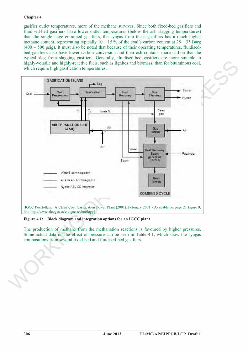
There are many variations in the basic layout of an IGCC plant, with the level of integration between the units being the fundamental aspect of the design. Figure 4.1 shows the typical configuration of an IGCC plant, and its integration possibilities.
Some methane is always produced by decomposition of the coal’s volatile matter and by thermal reactions of the higher-molecular weight primary devolatilisation products. At lower
WORKIN
G DRAFT IN
PROGRESS
Chapter 4
306 June 2013 TL/MC/AP/EIPPCB/LCP_Draft 1
gasifier outlet temperatures, more of the methane survives. Since both fixed-bed gasifiers and fluidised-bed gasifiers have lower outlet temperatures (below the ash slagging temperatures) than the single-stage entrained gasifiers, the syngas from these gasifiers has a much higher methane content, representing typically 10 – 15 % of the coal’s carbon content at 28 – 35 Barg (400 – 500 psig). It must also be noted that because of their operating temperatures, fluidised-bed gasifiers also have lower carbon conversion and their ash contains more carbon that the typical slag from slagging gasifiers. Generally, fluidised-bed gasifiers are more suitable to highly-volatile and highly-reactive fuels, such as lignites and biomass, than for bituminous coal, which require high gasification temperatures.
[IGCC Puertollano. A Clean Coal Gasification Power Plant (2001). February 2001 - Available on page 21 figure 9, link http://www.elcogas.es/en/igcc-technology]
Figure 4.1: Block diagram and integration options for an IGCC plant
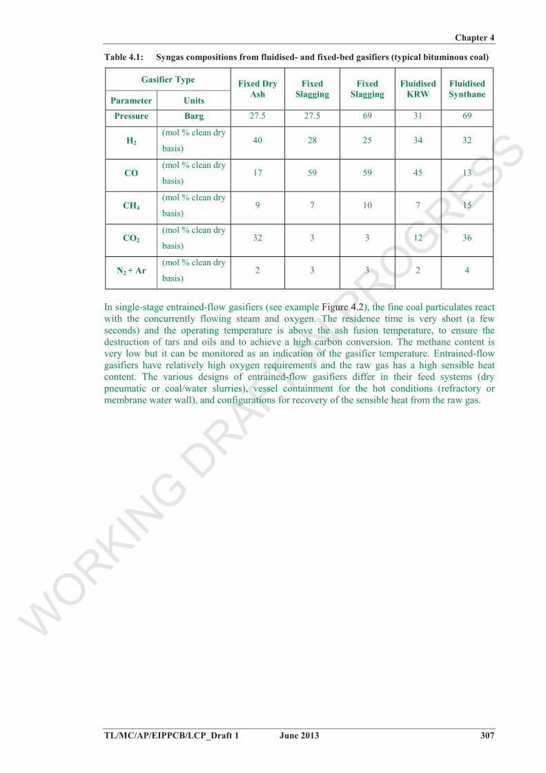
The production of methane from the methanation reactions is favoured by higher pressures. Some actual data on the effect of pressure can be seen in Table 4.1, which show the syngas compositions from several fixed-bed and fluidised-bed gasifiers.
WORKIN
G DRAFT IN
PROGRESS
Chapter 4
TL/MC/AP/EIPPCB/LCP_Draft 1 June 2013 307
Table 4.1: Syngas compositions from fluidised- and fixed-bed gasifiers (typical bituminous coal)
Gasifier Type
Parameter Units
Fixed Dry Ash
Fixed Slagging
Fixed Slagging
Fluidised KRW
Fluidised Synthane
Pressure Barg 27.5 27.5 69 31 69
H2(mol % clean dry
basis)40 28 25 34 32
CO(mol % clean dry
basis)17 59 59 45 13
CH4(mol % clean dry
basis)9 7 10 7 15
CO2(mol % clean dry
basis)32 3 3 12 36
N2 + Ar (mol % clean dry
basis)2 3 3 2 4
In single-stage entrained-flow gasifiers (see example Figure 4.2), the fine coal particulates react with the concurrently flowing steam and oxygen. The residence time is very short (a few seconds) and the operating temperature is above the ash fusion temperature, to ensure the destruction of tars and oils and to achieve a high carbon conversion. The methane content is very low but it can be monitored as an indication of the gasifier temperature. Entrained-flow gasifiers have relatively high oxygen requirements and the raw gas has a high sensible heat content. The various designs of entrained-flow gasifiers differ in their feed systems (dry pneumatic or coal/water slurries), vessel containment for the hot conditions (refractory or membrane water wall), and configurations for recovery of the sensible heat from the raw gas.
WORKIN
G DRAFT IN
PROGRESS
Chapter 4
308 June 2013 TL/MC/AP/EIPPCB/LCP_Draft 1
Figure 4.2: GE single-stage entrained-flow gasifier
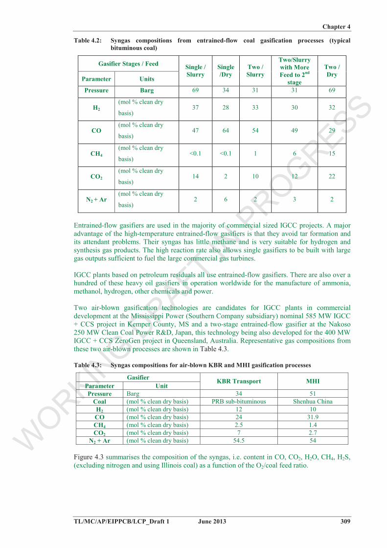
Some gasifier designs use two stages to improve the gasifier cold gas efficiency, to reduce the sensible heat in the raw gas, and to lower the oxygen requirements. In a two-stage entrained-flow gasifier, the coal fed to the second stage reduces the outlet temperature and produces some methane that survives in the syngas. The methane content will increase if a higher proportion of the coal is fed to the second stage. The typical syngas compositions from several entrained-flow gasification processes are shown in Table 4.2.
Entrained-flow gasifiers are used in the majority of commercial sized IGCC projects. A major advantage of the high-temperature entrained-flow gasifiers is that they avoid tar formation and its attendant problems. Their syngas has little methane and is very suitable for hydrogen and synthesis gas products. The high reaction rate also allows single gasifiers to be built with large gas outputs sufficient to fuel the large commercial gas turbines.
IGCC plants based on petroleum residuals all use entrained-flow gasifiers. There are also over a hundred of these heavy oil gasifiers in operation worldwide for the manufacture of ammonia, methanol, hydrogen, other chemicals and power.
Two air-blown gasification technologies are candidates for IGCC plants in commercial development at the Mississippi Power (Southern Company subsidiary) nominal 585 MW IGCC + CCS project in Kemper County, MS and a two-stage entrained-flow gasifier at the Nakoso 250 MW Clean Coal Power R&D, Japan, this technology being also developed for the 400 MW IGCC + CCS ZeroGen project in Queensland, Australia. Representative gas compositions from these two air-blown processes are shown in Table 4.3.
Table 4.3: Syngas compositions for air-blown KBR and MHI gasification processes
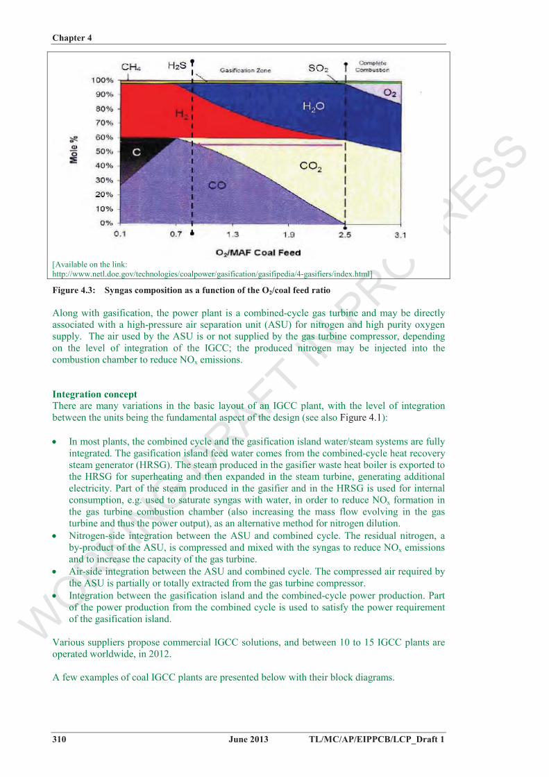
Figure 4.3 summarises the composition of the syngas, i.e. content in CO, CO2, H2O, CH4, H2S, (excluding nitrogen and using Illinois coal) as a function of the O2/coal feed ratio.
WORKIN
G DRAFT IN
PROGRESS
Chapter 4
310 June 2013 TL/MC/AP/EIPPCB/LCP_Draft 1
[Available on the link: http://www.netl.doe.gov/technologies/coalpower/gasification/gasifipedia/4-gasifiers/index.html]
Figure 4.3: Syngas composition as a function of the O2/coal feed ratio
Along with gasification, the power plant is a combined-cycle gas turbine and may be directly associated with a high-pressure air separation unit (ASU) for nitrogen and high purity oxygen supply. The air used by the ASU is or not supplied by the gas turbine compressor, depending on the level of integration of the IGCC; the produced nitrogen may be injected into the combustion chamber to reduce NOx emissions.
Integration concept There are many variations in the basic layout of an IGCC plant, with the level of integration between the units being the fundamental aspect of the design (see also Figure 4.1):
In most plants, the combined cycle and the gasification island water/steam systems are fully integrated. The gasification island feed water comes from the combined-cycle heat recovery steam generator (HRSG). The steam produced in the gasifier waste heat boiler is exported to the HRSG for superheating and then expanded in the steam turbine, generating additional electricity. Part of the steam produced in the gasifier and in the HRSG is used for internal consumption, e.g. used to saturate syngas with water, in order to reduce NOx formation in the gas turbine combustion chamber (also increasing the mass flow evolving in the gas turbine and thus the power output), as an alternative method for nitrogen dilution.
Nitrogen-side integration between the ASU and combined cycle. The residual nitrogen, a by-product of the ASU, is compressed and mixed with the syngas to reduce NOx emissions and to increase the capacity of the gas turbine.
Air-side integration between the ASU and combined cycle. The compressed air required by the ASU is partially or totally extracted from the gas turbine compressor.
Integration between the gasification island and the combined-cycle power production. Part of the power production from the combined cycle is used to satisfy the power requirement of the gasification island.
Various suppliers propose commercial IGCC solutions, and between 10 to 15 IGCC plants are operated worldwide, in 2012.
A few examples of coal IGCC plants are presented below with their block diagrams.
WORKIN
G DRAFT IN
PROGRESS
Chapter 4
TL/MC/AP/EIPPCB/LCP_Draft 1 June 2013 311
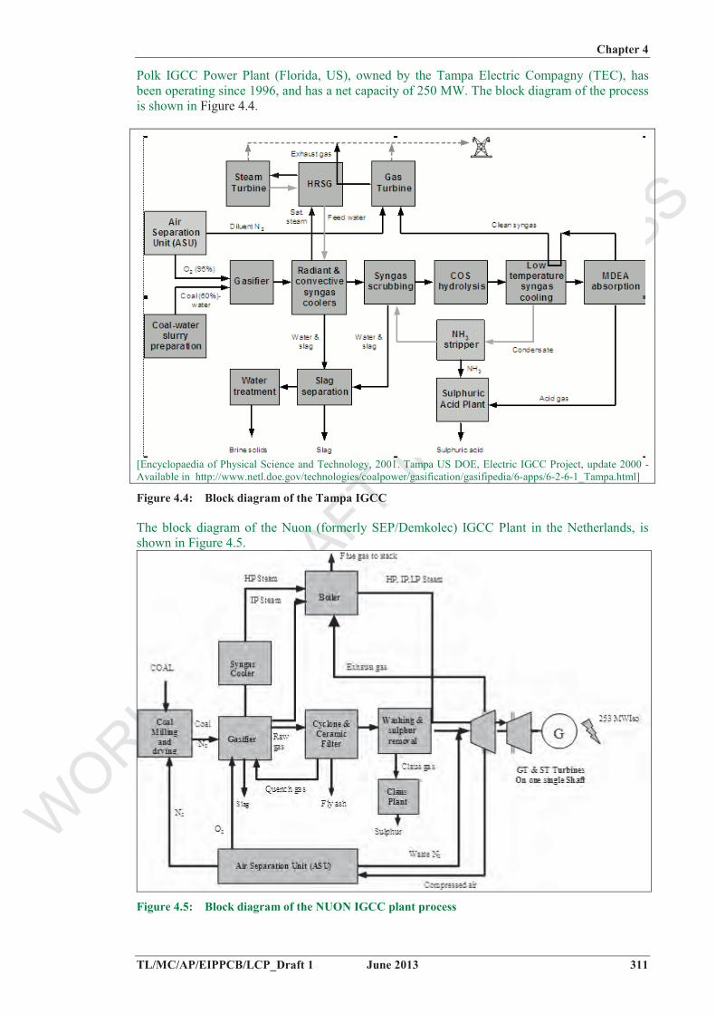
Polk IGCC Power Plant (Florida, US), owned by the Tampa Electric Compagny (TEC), has been operating since 1996, and has a net capacity of 250 MW. The block diagram of the process is shown in Figure 4.4.
[Encyclopaedia of Physical Science and Technology, 2001. Tampa US DOE, Electric IGCC Project, update 2000 - Available in http://www.netl.doe.gov/technologies/coalpower/gasification/gasifipedia/6-apps/6-2-6-1_Tampa.html]
Figure 4.4: Block diagram of the Tampa IGCC
The block diagram of the Nuon (formerly SEP/Demkolec) IGCC Plant in the Netherlands, is shown in Figure 4.5.
Figure 4.5: Block diagram of the NUON IGCC plant process
WORKIN
G DRAFT IN
PROGRESS
Chapter 4
312 June 2013 TL/MC/AP/EIPPCB/LCP_Draft 1
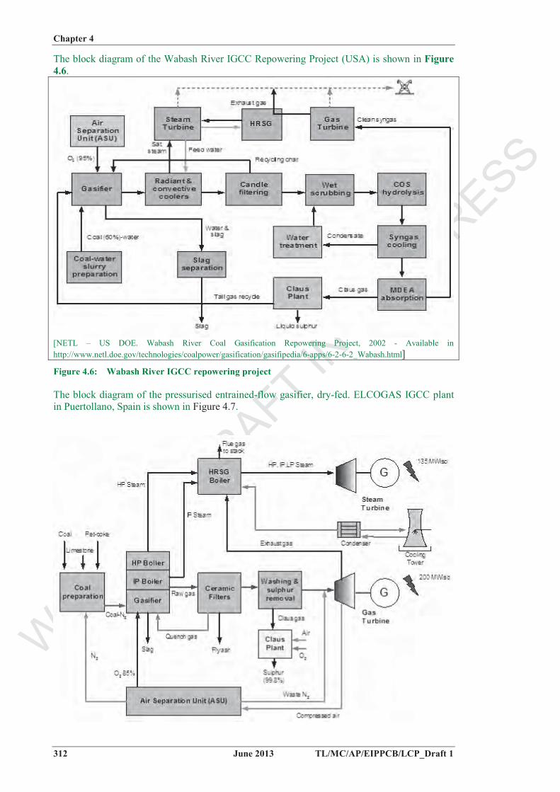
The block diagram of the Wabash River IGCC Repowering Project (USA) is shown in Figure 4.6.
[NETL – US DOE. Wabash River Coal Gasification Repowering Project, 2002 - Available in http://www.netl.doe.gov/technologies/coalpower/gasification/gasifipedia/6-apps/6-2-6-2_Wabash.html]
Figure 4.6: Wabash River IGCC repowering project
The block diagram of the pressurised entrained-flow gasifier, dry-fed. ELCOGAS IGCC plant in Puertollano, Spain is shown in Figure 4.7.
WORKIN
G DRAFT IN
PROGRESS
Chapter 4
TL/MC/AP/EIPPCB/LCP_Draft 1 June 2013 313
Figure 4.7: Block diagram of the Elcogas IGCC plant process.
IGCC plants based on fossil fuels other than coal In Europe and Asia, most of the refinery IGCC plants are based on various refinery heavy oil streams (e.g., vacuum resid, deasphalter bottoms, visbreaker residue), while in the US, petroleum coke is more often considered as the feedstock for IGCC plants.
Heavy oil gasification Heavy oil gasification technology has been widely commercially available since the 1950s with more than 200 units licensed worldwide. Most of the applications prior to 1990 were to supply syngas for chemical manufacture or hydrogen to refineries. The IGCC application only appeared in the 1990s. Available gasifiers are based on single fuel injector, down flow, oxygen blown, refractory lined, entrained-flow reactors:
Three plants in Italy entered full commercial service in 2001. These are Isab Energy S.r.l. 510 MW in Sicily (Italy), Api Energia 260 MW in Falconara (Italy) and Sarlux 550 MW in Sardinia (Italy). In 2000, three additional heavy oil gasification plants were commissioned (1 in US and 2 in Singapore). In 2003, a single train 342 MW IGCC entered commercial service at the Negishi refinery in Japan. Several other gasifiers operating on heavy oil/pitch have also been supplied to China and India in the past decade, most of them being for ammonia, chemicals and fuel gas, not for IGCC.
Pernis (Netherlands), ENI, Sannazzaro-Ferrera E. (Italy) are other example IGCC plants gasifying heavy oil in refineries.
Petroleum coke gasification The main gasification technologies are able to use pet-coke as fuel:
Coffeyville Resources (US) uses pet-coke to produce hydrogen for ammonia manufacture; some of the captured CO2 is used to form urea through reaction with some of the produced ammonia, and it also provides CO2 for enhanced oil recovery (EOR). Also the Tampa IGCC plant in Polk County, Florida usually runs on a mixture of 55 % petroleum coke and 45 % coal in order to reduce feedstock prices.
Elcogas IGCC runs on a 50/50 mixture of petroleum coke. Since the conclusion of the DOE demonstration program in January 2000, the Wabash plant
has been running on 100 % petroleum coke.
4.1.2 Biomass gasifiers
The incentive for biomass gasification is generally attributed to the potential for a much higher power generation efficiency with a biomass IGCC or with the multi-fuel firing of biomass gas in existing boilers, than can be accomplished with direct combustion boilers and steam turbines in the smaller size range appropriate for dedicated biomass projects. Because of the nature of biomass, and the economics and logistics of its gathering and supply, such projects are generally considered in the much smaller 10 – 190 MWth size range than the larger 500 MWth coal-based IGCC plants or other coal-fired units, so the main challenge for potential projects is the diseconomy of scale. Because of the heightened concern over global warming, there is an increased interest in renewable energy projects, including those associated with biomass
The availability of biomass is a limiting factor for the commercialisation of biomass gasifications. However, the occurrence of tars in syngas is also a major problem that has to be overcome in striving to commercialise biomass gasification processes for various purposes, and efforts by vendors and research organisations to alleviate this problem are ongoing. The use of entrained-flow gasifiers may eliminate tar problems, but these are mainly suited to large industrial-scale gasification (> 100 MWth), and therefore generally not relevant for most biomass gasification applications [Brandin et al., 2011]. However it has been demonstrated in
WORKIN
G DRAFT IN
PROGRESS
Chapter 4
314 June 2013 TL/MC/AP/EIPPCB/LCP_Draft 1
coal-based IGCC (Nuon Buggenon, the Netherlands – Elcogas Puertollano, Spain) the easy viability of biomass cogasification in small relative percentages, that still represents considerable biomass power (5 – 30 % of biomass as fuel represents up to 30 – 200 MWth).
There are two main strategies for dealing with the tar once it is present in the syngas: removal or in situ conversion. Removal includes wet/oil-scrubbing systems; partial oxidation and catalytic tar cracking are examples of in situ conversion methods [Brandin et al., 2011]. Another solution for conversion is to keep the gas above the tar dew point and use the tar as a part of the gas to be combusted in the boiler, which increases the energy efficiency by 5 to 10 %. [Power-Gen Europe 2012 - Vaskiluoto plant]
Fixed-bed (updraft and downdraft) and fluidised-bed gasifiers are the three primary varieties of biomass gasification technologies; they are mainly applicable on a small or medium scale.
Updraft and downdraft fixed-bed designs are less complex than a fluidised-bed, but generate lower energy value syngas and are most suitable for small-scale biomass gasification (in the range of a few hundred kWth). The market attractiveness for fixed-bed biomass gasifiers of a scale relevant for this document (> 20 MWth rated input) is currently very limited.
Most of the larger biomass gasification projects in both the US and Europe are based on fluidised-bed gasification under either atmospheric or pressurised conditions.
Circulating and bubbling fluidised bed
Fluidised-bed gasifiers may be circulating (CFB) or bubbling (BFB), and are most useful for fuels, such as biomass, that normally would form corrosive ash, which would damage the walls of a slagging gasifier. CFB/BFB fluidised-bed gasifiers produce higher fuel value syngas and accept a wider range of feedstocks, compared to updraft and downdraft fixed bed gasifiers. They are well suited for continuous operation and scalable to a wide range of sizes, allowing for large-scale industrial plants. Hence, CFB/BFB fluidized bed gasifiers are state-of-the art technology for biomass gasification at a scale covered in this document (> 20 MWth).
CFB/BFB fluidised-bed gasifiers may be air-blown, oxygen-blown and/or steam-blown and operate at pressurised or atmospheric pressure. Steam and oxygen or air are introduced below the fluidised-bed, which is suspended by the fluidisation gases. In a BFB-gasifier, the fuel is fed into the dense bed, flows upwards through the reactor tower, and remains suspended in this stream while gasification takes place. Moderate temperature syngas exits the top of the reactor, while dry (unmelted) ash is evacuated at the bottom. Issues to be addressed in the design include the quality and replenishment of the heat transfer medium and erosion of the reactors (Pytlar, 2010).
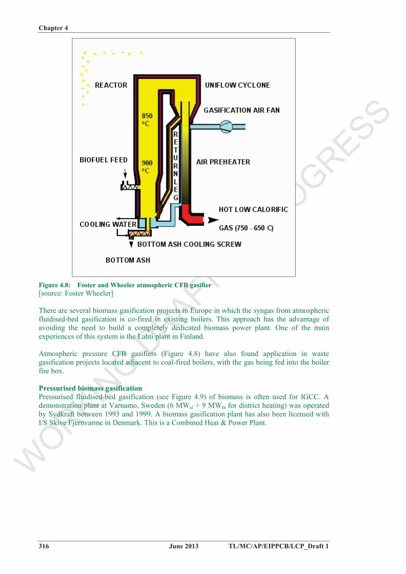
The Circulating Fluidised Bed (CFB) gasifier (see Figure 4.8: Foster and Wheeler atmospheric CFB gasifierconsists of a reactor where the air-blown fluidised gasification takes place, a cyclone to separate the circulating bed material from the gas, and a return pipe for returning the circulating material to the bottom part of the gasifier.
Ranges of syngas compositions from CFB and BFB biomass gasifiers are shown in Figure 4.8
WORKIN
G DRAFT IN
PROGRESS
Chapter 3
315 June 2013
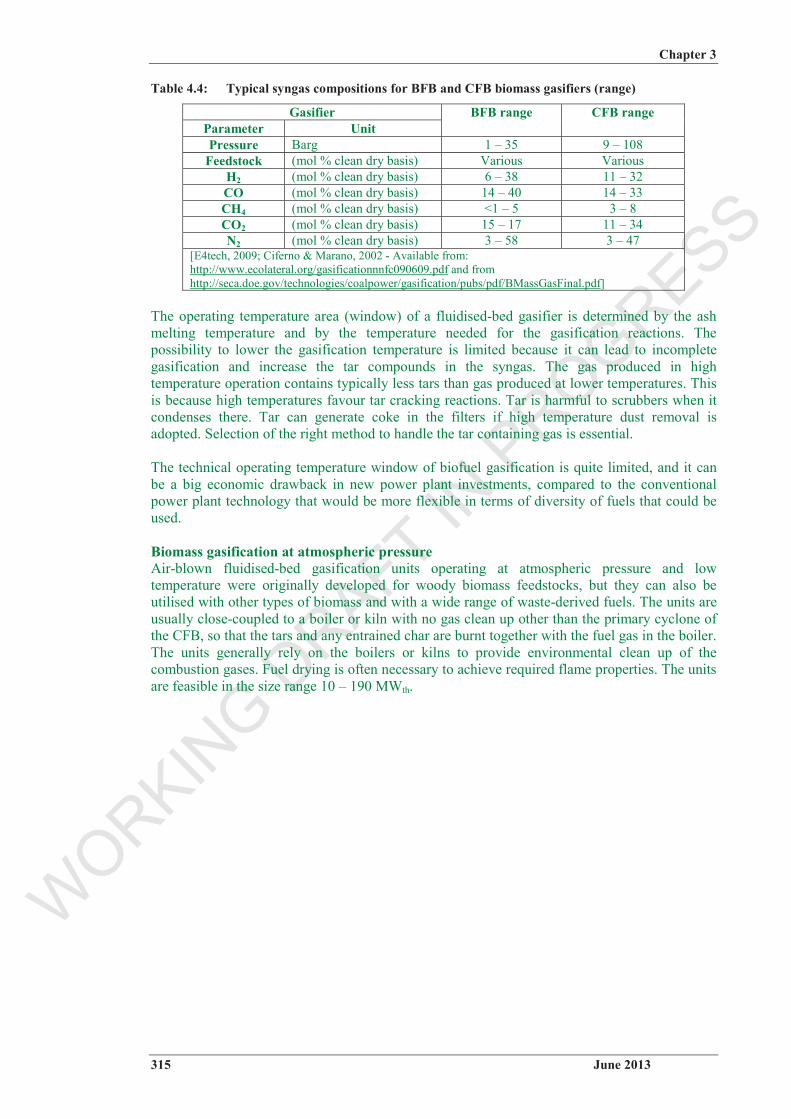
Table 4.4: Typical syngas compositions for BFB and CFB biomass gasifiers (range)
Gasifier Parameter Unit
BFB range CFB range
Pressure Barg 1 – 35 9 – 108 Feedstock (mol % clean dry basis) Various Various
[E4tech, 2009; Ciferno & Marano, 2002 - Available from: http://www.ecolateral.org/gasificationnnfc090609.pdf and from http://seca.doe.gov/technologies/coalpower/gasification/pubs/pdf/BMassGasFinal.pdf]
The operating temperature area (window) of a fluidised-bed gasifier is determined by the ash melting temperature and by the temperature needed for the gasification reactions. The possibility to lower the gasification temperature is limited because it can lead to incomplete gasification and increase the tar compounds in the syngas. The gas produced in high temperature operation contains typically less tars than gas produced at lower temperatures. This is because high temperatures favour tar cracking reactions. Tar is harmful to scrubbers when it condenses there. Tar can generate coke in the filters if high temperature dust removal is adopted. Selection of the right method to handle the tar containing gas is essential.
The technical operating temperature window of biofuel gasification is quite limited, and it can be a big economic drawback in new power plant investments, compared to the conventional power plant technology that would be more flexible in terms of diversity of fuels that could be used.
Biomass gasification at atmospheric pressure Air-blown fluidised-bed gasification units operating at atmospheric pressure and low temperature were originally developed for woody biomass feedstocks, but they can also be utilised with other types of biomass and with a wide range of waste-derived fuels. The units are usually close-coupled to a boiler or kiln with no gas clean up other than the primary cyclone of the CFB, so that the tars and any entrained char are burnt together with the fuel gas in the boiler. The units generally rely on the boilers or kilns to provide environmental clean up of the combustion gases. Fuel drying is often necessary to achieve required flame properties. The units are feasible in the size range 10 – 190 MWth.
There are several biomass gasification projects in Europe in which the syngas from atmospheric fluidised-bed gasification is co-fired in existing boilers. This approach has the advantage of avoiding the need to build a completely dedicated biomass power plant. One of the main experiences of this system is the Lahti plant in Finland.
Atmospheric pressure CFB gasifiers (Figure 4.8) have also found application in waste gasification projects located adjacent to coal-fired boilers, with the gas being fed into the boiler fire box.
Pressurised biomass gasificationPressurised fluidised-bed gasification (see Figure 4.9) of biomass is often used for IGCC. A demonstration plant at Varnamo, Sweden (6 MWel + 9 MWth for district heating) was operated by Sydkraft between 1993 and 1999. A biomass gasification plant has also been licensed with I/S Skive Fjernvarme in Denmark. This is a Combined Heat & Power Plant.
Co-gasification of biomass in IGCC plants and coal gasifiers Large amounts of biomass and wastes (5 – 25 t/h) can be added to the feed in coal gasifiers without compromising the operation or quality of the slag, by limiting the percentage of biomass in the fuel. These limits are mainly determined by the defined syngas clean up systems and the specific composition of used biomass. Some biomass ashes are high in alkalis, such as Na and K, which at some percentage usage could increase fouling and could negatively impact the slag leaching properties.
An example of a co-gasification plant is the Nuon Buggenum gasifier, which can now handle up to 15 % (LHV basis) clean white wood without significant modification; 30 % (LHV basis)biomass has been permitted and up to 70 % (LHV basis) is tested with refined biomass. Elcogas IGCC has also demonstrated viability for feed with 2 – 10 % of biomass (2 – 10 t/h), without any relevant modification in the preinstalled equipment.
Biomass gasification connected to coal boilers Fluidised-bed biomass gasifiers linked to combustion processes can be divided into two main categories: CFB/BFB gasifiers directly connected to a boiler, and CFB/BFB gasifiers with gas filtration/cleaning. The filtered syngas can be used for co-combustion in PC-boilers the same way as unfiltered biomass-derived gas. In addition, clean gas can be combusted alone in large-scale boilers designed for gaseous fuels. The clean gas can also be used for other applications, such as SNG (Synthetic Natural Gas) production, and hence the CFB/BFB gasifiers with gas filtration/cleaning can be further classified into two sub-categories, depending on the main product application:
connected to a boiler/gas engine (for power production); for SNG (Synthetic Natural Gas) production.
SNG can e.g. be used in the natural gas grid, or for transport purposes, but these applications are not included in this document. However, SNG production plants can also include the possibility for some of the SNG to be used in a gas engine or gas turbine; these are covered by this document.
Figure 4.1 illustrates different gasification and gas cleaning options.
WORKIN
G DRAFT IN
PROGRESS
Chapter 4
318 June 2013 TL/MC/AP/EIPPCB/LCP_Draft 1
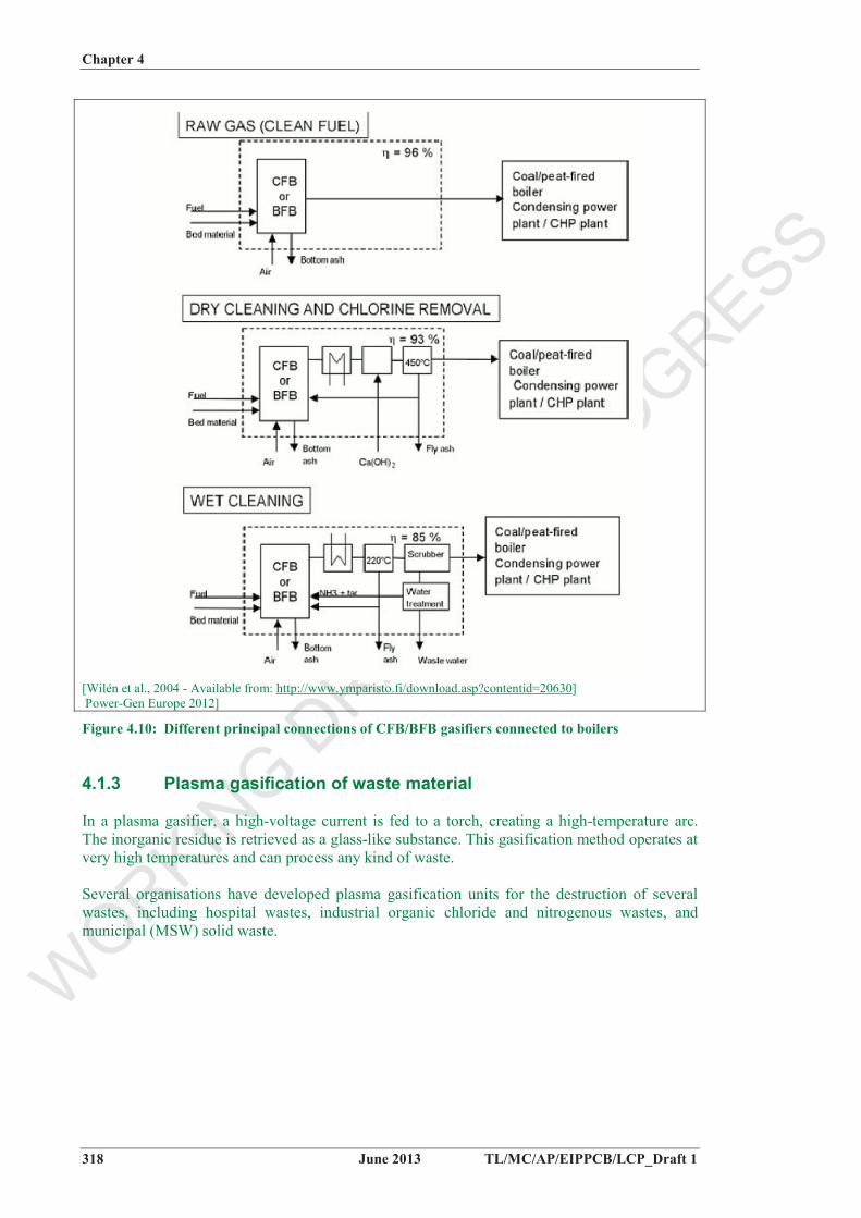
[Wilén et al., 2004 - Available from: http://www.ymparisto.fi/download.asp?contentid=20630] Power-Gen Europe 2012]
Figure 4.10: Different principal connections of CFB/BFB gasifiers connected to boilers
4.1.3 Plasma gasification of waste material
In a plasma gasifier, a high-voltage current is fed to a torch, creating a high-temperature arc. The inorganic residue is retrieved as a glass-like substance. This gasification method operates at very high temperatures and can process any kind of waste.
Several organisations have developed plasma gasification units for the destruction of several wastes, including hospital wastes, industrial organic chloride and nitrogenous wastes, and municipal (MSW) solid waste.
WORKIN
G DRAFT IN
PROGRESS
Chapter 4
TL/MC/AP/EIPPCB/LCP_Draft 1 June 2013 319
4.2 Current emissions and consumption levels
The main environmental issues include:
waste water release (organic content, cyanides, sulphides, ammonia, heavy metals); waste and by product generation: slag, bottom/fly ash, sulphur/sulphuric acid from the
desulphurisation stage, used/saturated catalyst; consumption of water, chemicals (solvent) and energy; fuel handling and pretreatment (diffuse emissions such as dust, VOCs); should the process be integrated with combustion: overall influence on energy
efficiency and on air/water emissions, synergies/drawbacks induced by the integration.
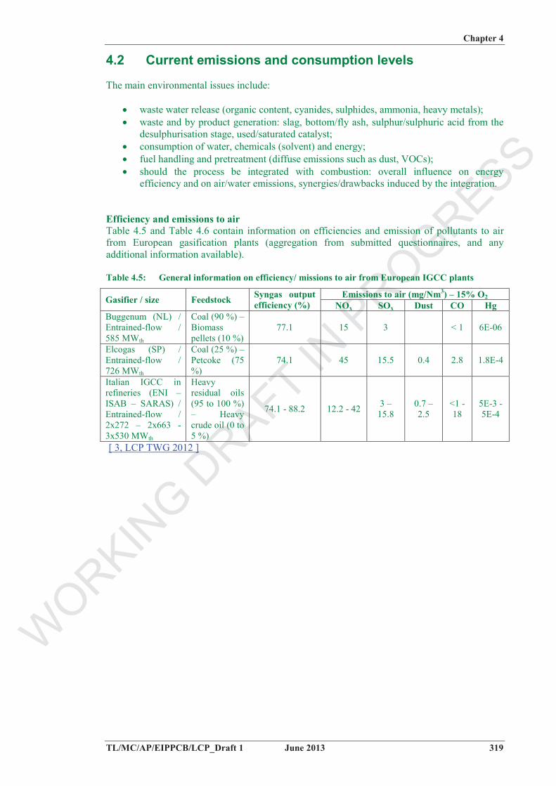
Efficiency and emissions to air Table 4.5 and Table 4.6 contain information on efficiencies and emission of pollutants to air from European gasification plants (aggregation from submitted questionnaires, and any additional information available).
Table 4.5: General information on efficiency/ missions to air from European IGCC plants
Emissions to air (mg/Nm3) – 15% O2Gasifier / size Feedstock Syngas output efficiency (%) NOx SOx Dust CO Hg
Buggenum (NL) / Entrained-flow / 585 MWth
Coal (90 %) – Biomass pellets (10 %)
77.1 15 3 < 1 6E-06
Elcogas (SP) / Entrained-flow / 726 MWth
Coal (25 %) – Petcoke (75 %)
74.1 45 15.5 0.4 2.8 1.8E-4
Italian IGCC in refineries (ENI – ISAB – SARAS) / Entrained-flow / 2x272 – 2x663 - 3x530 MWth
Heavy residual oils (95 to 100 %) – Heavy crude oil (0 to 5 %)
74.1 - 88.2 12.2 - 42 3 – 15.8
0.7 – 2.5
<1 - 18
5E-3 - 5E-4
[ 3, LCP TWG 2012 ]
WORKIN
G DRAFT IN
PROGRESS
Chapter 4
320 June 2013 TL/MC/AP/EIPPCB/LCP_Draft 1
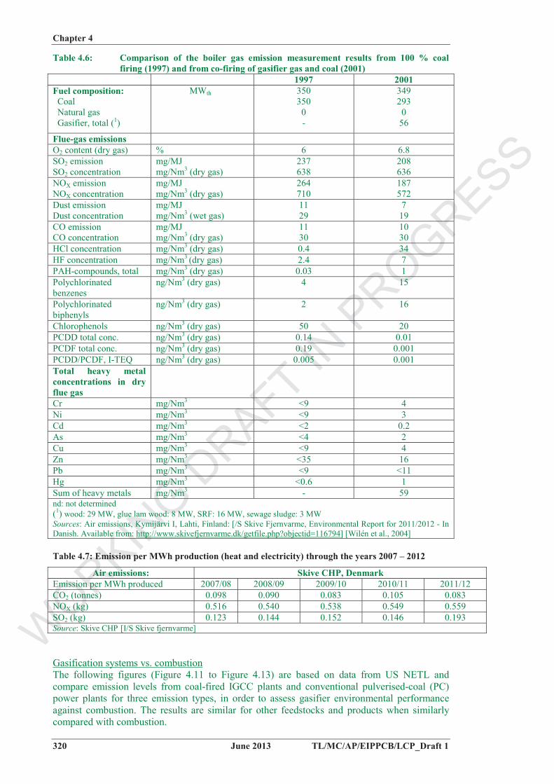
Table 4.6: Comparison of the boiler gas emission measurement results from 100 % coal firing (1997) and from co-firing of gasifier gas and coal (2001)
1997 2001 Fuel composition: Coal Natural gas Gasifier, total (1)
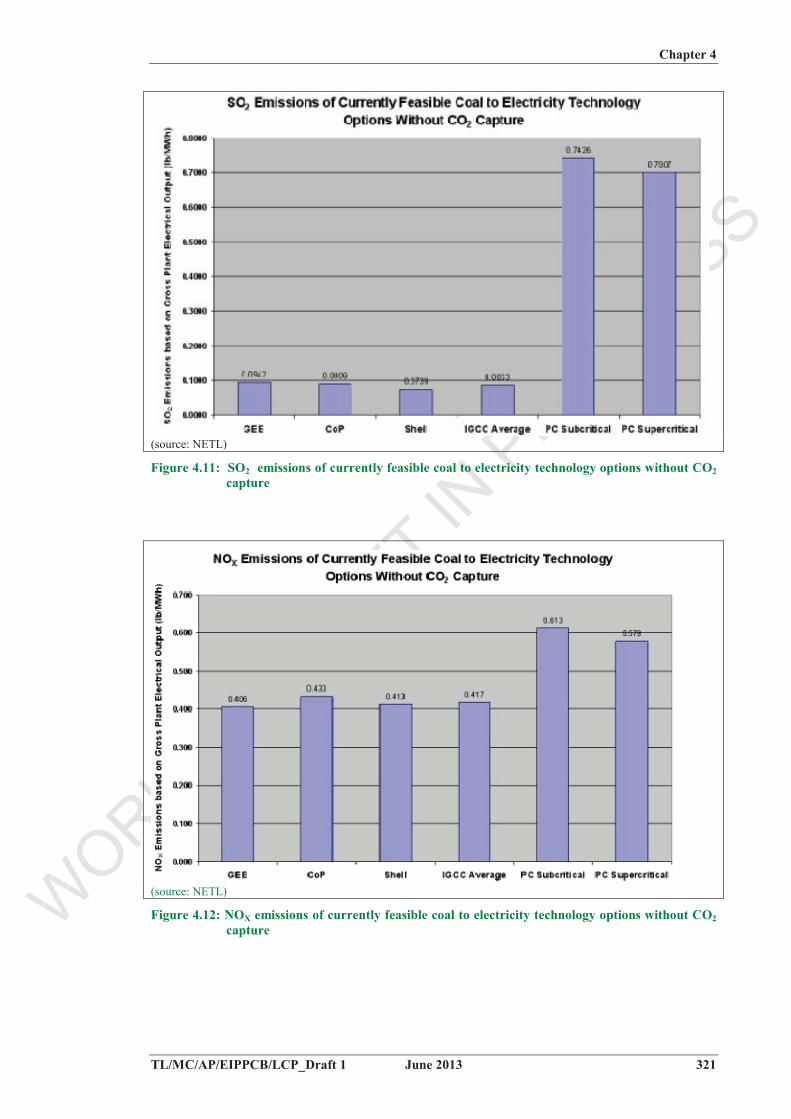
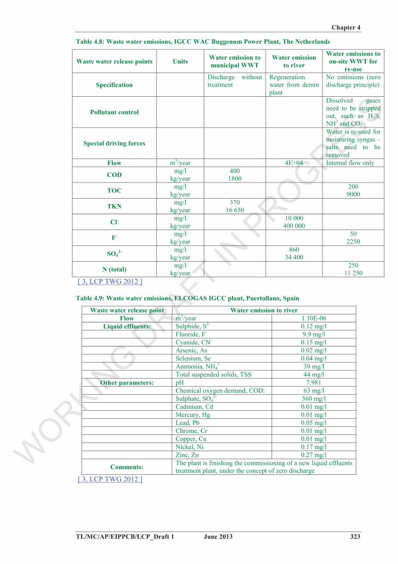
Gasification systems vs. combustionThe following figures (Figure 4.11 to Figure 4.13) are based on data from US NETL and compare emission levels from coal-fired IGCC plants and conventional pulverised-coal (PC) power plants for three emission types, in order to assess gasifier environmental performance against combustion. The results are similar for other feedstocks and products when similarly compared with combustion.
WORKIN
G DRAFT IN
PROGRESS
Chapter 4
TL/MC/AP/EIPPCB/LCP_Draft 1 June 2013 321
(source: NETL)
Figure 4.11: SO2 emissions of currently feasible coal to electricity technology options without CO2capture
(source: NETL)
Figure 4.12: NOX emissions of currently feasible coal to electricity technology options without CO2capture
WORKIN
G DRAFT IN
PROGRESS
Chapter 4
322 June 2013 TL/MC/AP/EIPPCB/LCP_Draft 1
(source: NETL)
Figure 4.13: Particulate emissions of currently feasible coal to electricity technology options without CO2 capture
Figure 4.11 shows that when all else is even, the current IGCC technologies provide nearly an order of magnitude reduction in SO2 emissions compared with their PC counterparts.
Figure 4.12 shows that known methods for controlling NOx formation keep these levels to a minimum in IGCC and result in NOx emissions far below those associated with PC firing. During gasification, most of the nitrogen in the coal is converted into nitrogen gas (N2). Small levels of ammonia (NH3) and hydrogen cyanide (HCN) are produced, however, and can be removed during the syngas cleaning process.
Figure 4.13 illustrates that gasification offers two main advantages for dust control over combustion processes. First, gasification of coal provides the capability of removing most of the ash as slag or bottom ash for disposal or sale as a by-product. Secondly, since the syngas leaving the gasifier is much denser than combustion exhaust gases, dust can be removed more easily with a proper gas cleaning system, to get a syngas quality similar or better than natural gas, as required by the final use, and allowing better optimisation of the environmental and efficiency performance.
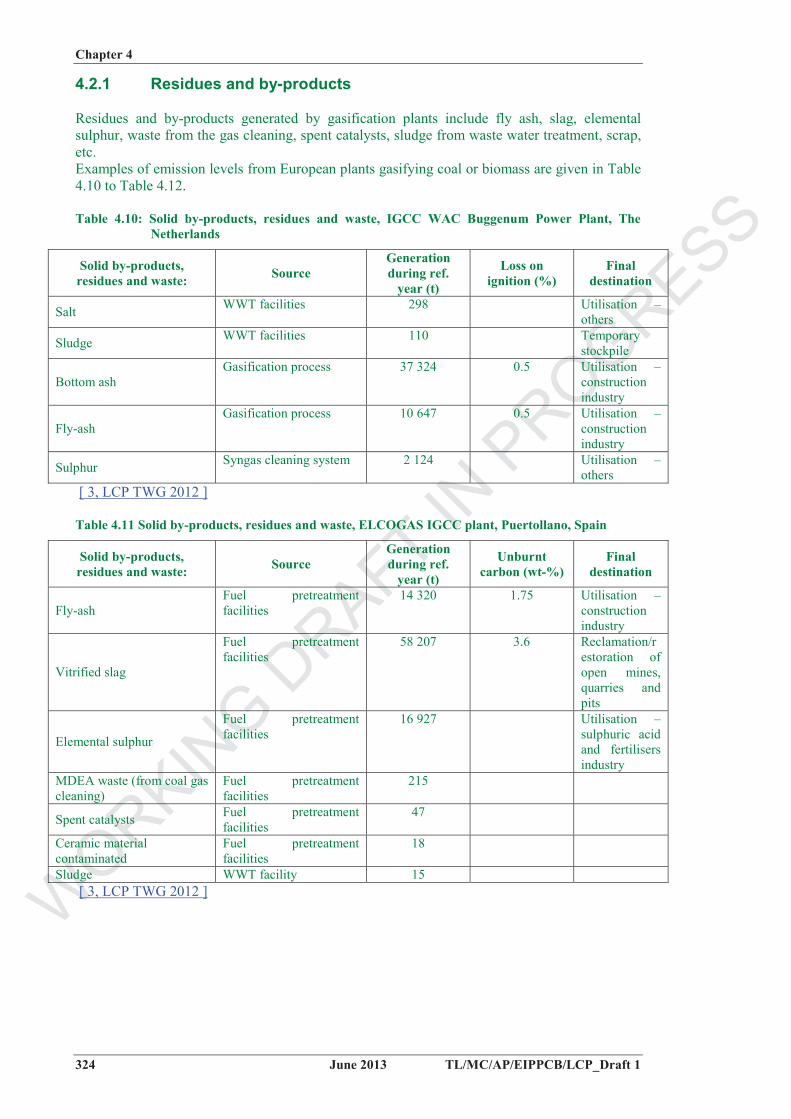
Emissions to water The water emissions correspond to the waste water released at specific release points and to the WWT facilities of only the gasification plant and its auxiliary systems. Examples of emission levels from the European IGCC plants gasifying coal are given in Table 4.8 and Table 4.9.
WORKIN
G DRAFT IN
PROGRESS
Chapter 4
TL/MC/AP/EIPPCB/LCP_Draft 1 June 2013 323
Table 4.8: Waste water emissions, IGCC WAC Buggenum Power Plant, The Netherlands
Waste water release points Units Water emission to municipal WWT
Water emission to river
Water emissions to on-site WWT for
re-use
SpecificationDischarge without treatment
Regeneration water from demin plant
No emissions (zero discharge principle)
Pollutant control
Dissolved gases need to be stripped out, such as H2S, NH3 and CO2
Special driving forces
Water is re-used for moisturing syngas – salts need to be removed
Flow m3/year 4E+04 Internal flow only
COD mg/l kg/year
4001800
TOC mg/l kg/year
200 9000
TKN mg/l kg/year
37016 650
Cl- mg/l kg/year
10 000 400 000
F- mg/l kg/year
50 2250
SO42- mg/l
kg/year 860
34 400
N (total) mg/l kg/year
250 11 250
[ 3, LCP TWG 2012 ]
Table 4.9: Waste water emissions, ELCOGAS IGCC plant, Puertollano, Spain
Waste water release point Water emission to river Flow m3/year 1.10E-06
Comments: The plant is finishing the commissioning of a new liquid effluents treatment plant, under the concept of zero discharge
[ 3, LCP TWG 2012 ]
WORKIN
G DRAFT IN
PROGRESS
Chapter 4
324 June 2013 TL/MC/AP/EIPPCB/LCP_Draft 1
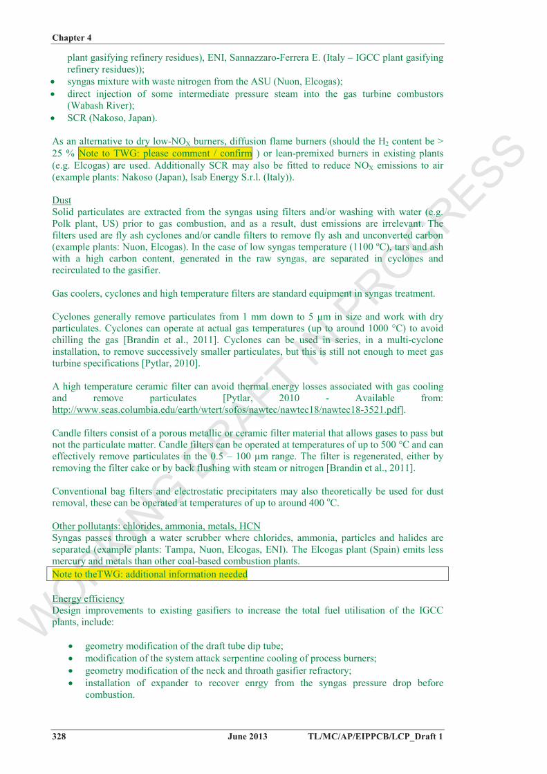
4.2.1 Residues and by-products
Residues and by-products generated by gasification plants include fly ash, slag, elemental sulphur, waste from the gas cleaning, spent catalysts, sludge from waste water treatment, scrap, etc.Examples of emission levels from European plants gasifying coal or biomass are given in Table 4.10 to Table 4.12.
Table 4.10: Solid by-products, residues and waste, IGCC WAC Buggenum Power Plant, The Netherlands
Solid by-products, residues and waste: Source
Generation during ref.
year (t)
Loss on ignition (%)
Final destination
Salt WWT facilities 298 Utilisation – others
Sludge WWT facilities 110 Temporary stockpile
Bottom ash Gasification process 37 324 0.5 Utilisation –
construction industry
Fly-ash Gasification process 10 647 0.5 Utilisation –
construction industry
Sulphur Syngas cleaning system 2 124 Utilisation –others
58 207 3.6 Reclamation/restoration of open mines, quarries and pits
Elemental sulphur
Fuel pretreatment facilities
16 927 Utilisation – sulphuric acid and fertilisers industry
MDEA waste (from coal gas cleaning)
Fuel pretreatment facilities
215
Spent catalysts Fuel pretreatment facilities
47
Ceramic material contaminated
Fuel pretreatment facilities
18
Sludge WWT facility 15 [ 3, LCP TWG 2012 ]
WORKIN
G DRAFT IN
PROGRESS
Chapter 4
TL/MC/AP/EIPPCB/LCP_Draft 1 June 2013 325
Table 4.12: Solid by-products, residues and waste, Kymijärvi I, Lahti, Finland
Solid by-products, residues and waste Source
Generation during ref.
year (t)
Unburnt carbon (wt-%)
Final destination
Bottom ash (gasifier) The only direct solid output is gasifier bottom ash
2 810 Landfilling
[ 3, LCP TWG 2012 ]
4.2.2 Consumption of water, chemical and energy
Example of consumption levels from European plants gasifying coal or biomass are given in Table 4.13 to Table 4.16.
Table 4.13: Consumption data, IGCC WAC Buggenum Power Plant, The Netherlands
Consumption data Parameter Unit
Fuel energy input (as LHV) MWth 2 815 717 Syngas energy output (as LHV) MWth 2 171 191 Water:Total inlet flow m3/year 9.00E+04 Process water consumption m3/year 9.00E+04 Water for cooling system m3/year 2.79E+08 Comments Zero discharge in permit, most water (except cooling water) is recycled [ 3, LCP TWG 2012 ]
Fuel energy input (as LHV) MWth 3.28E+06 Syngas energy output (as LHV) MWth 2.43E+06 Water:Total inlet flow m3/year 5.74E+05 Process water m3/year 2.88E+05 Water for steam system m3/year 2.35E+05 Water for cooling system m3/year 1.82E+06 Comments Consumed water streams are lower than inlet, as more raw water is needed
for demin water production [ 3, LCP TWG 2012 ]
Table 4.15: Consumption data, Kymijärvi I, Lahti, Finland
Table 4.16 Consumption levels per MWh production (heat and electricity) through the years 2007 – 2012 for Skive CHP
Consumption data Parameters
Emission per MWh produced 2007/08 2008/09 2009/10 2010/11 2011/12 Water consumption (L) 236 279 146 176 201 Electricity consumption (kWh) 24 31 32 30 42[I/S Skive fjernvarme]
WORKIN
G DRAFT IN
PROGRESS
Chapter 4
326 June 2013 TL/MC/AP/EIPPCB/LCP_Draft 1
4.2.3 Emissions to land / soil
Emissions to soil / land from gasification facilities may include unexpected incidences, such as leakages from waste water pipes.
WORKIN
G DRAFT IN
PROGRESS
Chapter 4
TL/MC/AP/EIPPCB/LCP_Draft 1 June 2013 327
4.3 Techniques to consider in the determination of BAT
4.3.1 Integrated gasification with the combustion process
This section presents relevant techniques to consider in the determination of BAT for gasification processes associated to combustion processes and with a minimum total rated thermal input of 20 MW. The gasification of refineries residues (e.g. heavy fuel oil) linked to combustion is not covered by this document but is by the Mineral Oil and Gas Refineries BREF. However, as the techniques used are the same as the ones used when gasifying coal of other feedstocks in an integrated way with combustion processes, information provided by such plants gasifying refineries residues is used to further improve the description of the techniques to consider in the determination of BAT.
4.3.1.1 Prevention of emissions and efficient energy use with coal and mulgifuel based Integrated Gasification Combined Cycle (IGCC) plants
Description Coal/mulgifuel gasification prior to combustion of the produced syngas in a combined cycle gas turbine is an alternative to direct coal combustion in a boiler and enables, by implementing a set of appropriate techniques to clean the produced syngas, lower pollutant emissions and a higher energy efficiency.
Technical description All IGCC plants have demonstrated lower or comparable SO2 and NOX emissions than those from a Pulverised Coal (PC) or Combined Cycle using natural gas (NGCC). Some pollutants, such as sulphur, can be turned into re-usable byproducts.
The plant is called integrated because (1) the syngas produced in the gasification section is used as fuel for the gas turbine in the combined cycle, and (2) steam produced by the syngas coolers in the gasification section is integrated in the normal steam cycle of the combined-cycle process. In a normal combined cycle, so-called waste heat from the gas turbine exhaust is used in a Heat Recovery Steam Generator (HRSG) to make steam for the steam turbine cycle.
SOX emissions to airSulphur compounds from the coal feed of a gasification process are generally removed from the syngas via an acid gas removal (AGR) process (e.g including a (HCN/)COS hydrolysis reactor and the absorption of H2S using a solvent such as MDEA amine or Sulfinol M Wash) as a concentrated hydrogen sulphide (H2S) stream. Sulphur is then recovered as either liquid or solid elemental sulphur (e.g. through a Claus unit), or as sulphuric acid, depending on market demands. In the case of the Nuon plant (the Netherlands), the remaining H2S levels are below 20 ppm by volume. In Nakoso (Japan), the H2S rich gas is burnt and the flue-gases scrubbed with limestone slurry to produce gypsum for sale, since there is very little market for elemental sulphur in Japan.
NOx emissions to airDue to the reducing atmosphere in which the gasification process takes place, the syngas does not contain NOX, but ammonia (NH3) in low proportions, which is eliminated during the gas cleaning process by water washing. In addition to dry low-NOX burners, other systems are used in the gas turbine, such as:
syngas saturation with hot water/steam recovered with low level heat or intermediate pressure steam available in the plant (example plants: Nuon, Elcogas, Wabash River, Isab Energy S.r.l. (Italy – IGCC plant gasifying refinery residues), Sarlux Sarroch (Italy – IGCC
syngas mixture with waste nitrogen from the ASU (Nuon, Elcogas); direct injection of some intermediate pressure steam into the gas turbine combustors
(Wabash River); SCR (Nakoso, Japan).
As an alternative to dry low-NOX burners, diffusion flame burners (should the H2 content be > 25 % Note to TWG: please comment / confirm ) or lean-premixed burners in existing plants (e.g. Elcogas) are used. Additionally SCR may also be fitted to reduce NOX emissions to air (example plants: Nakoso (Japan), Isab Energy S.r.l. (Italy)).
DustSolid particulates are extracted from the syngas using filters and/or washing with water (e.g. Polk plant, US) prior to gas combustion, and as a result, dust emissions are irrelevant. The filters used are fly ash cyclones and/or candle filters to remove fly ash and unconverted carbon (example plants: Nuon, Elcogas). In the case of low syngas temperature (1100 ºC), tars and ash with a high carbon content, generated in the raw syngas, are separated in cyclones and recirculated to the gasifier.
Gas coolers, cyclones and high temperature filters are standard equipment in syngas treatment.
Cyclones generally remove particulates from 1 mm down to 5 µm in size and work with dry particulates. Cyclones can operate at actual gas temperatures (up to around 1000 °C) to avoid chilling the gas [Brandin et al., 2011]. Cyclones can be used in series, in a multi-cyclone installation, to remove successively smaller particulates, but this is still not enough to meet gas turbine specifications [Pytlar, 2010].
A high temperature ceramic filter can avoid thermal energy losses associated with gas cooling and remove particulates [Pytlar, 2010 - Available from: http://www.seas.columbia.edu/earth/wtert/sofos/nawtec/nawtec18/nawtec18-3521.pdf].
Candle filters consist of a porous metallic or ceramic filter material that allows gases to pass but not the particulate matter. Candle filters can be operated at temperatures of up to 500 °C and can effectively remove particulates in the 0.5 – 100 µm range. The filter is regenerated, either by removing the filter cake or by back flushing with steam or nitrogen [Brandin et al., 2011].
Conventional bag filters and electrostatic precipitaters may also theoretically be used for dust removal, these can be operated at temperatures of up to around 400 oC.
Other pollutants: chlorides, ammonia, metals, HCNSyngas passes through a water scrubber where chlorides, ammonia, particles and halides are separated (example plants: Tampa, Nuon, Elcogas, ENI). The Elcogas plant (Spain) emits less mercury and metals than other coal-based combustion plants. Note to theTWG: additional information needed
Energy efficiencyDesign improvements to existing gasifiers to increase the total fuel utilisation of the IGCC plants, include:
geometry modification of the draft tube dip tube; modification of the system attack serpentine cooling of process burners; geometry modification of the neck and throath gasifier refractory; installation of expander to recover enrgy from the syngas pressure drop before
combustion.
WORKIN
G DRAFT IN
PROGRESS
Chapter 4
TL/MC/AP/EIPPCB/LCP_Draft 1 June 2013 329
Excess heat from the primary combustion and syngas-fired generation is then passed to a steam cycle, similar to a combined cycle gas turbine. This may result in improved efficiency compared to conventional pulverised-coal combustion but comparable to ultra-supercritical PC combustion. An IGCC plant improves the overall process efficiency by adding the higher-temperature steam produced by the gasification process to the steam turbine cycle. This steam is then used in steam turbines to produce additional electrical power.
To achieve an even higher energy efficiency the plant can be designed with full integration of the air supply unit (ASU) and the gas turbine, all the air fed to the ASU is then supplied (extracted) from the gas turbine compressor (example plant: Elcogas).
CO2 captureCO2 capture in IGCC plants is favoured by the high pressure of the gasification process. By means of the water-gas reaction CO + H2O CO2 + H2, the production of hydrogen can be increased, and CO2 directly captured by using commercial processes, such as MDEA or Selexol absorption technologies, at a pressure that requires less auxiliary power for gas compression. The high moisture content of quenched syngas enables the shift reaction to be conducted with little or no additional steam from the steam cycle.
Achieved environmental benefitsReduction in the emissions of SO2, NOx and particulates, as compared to coal-fired power plants. High efficiency and energy security. Ability to use lower-grade feedstock while keeping the same low emission levels. In conventional units, low-grade fuels usually result in higher emissions. Generation of marketable subproducts.
Environmental performance and operational data Desulphurisation scrubbing can be highly efficient, leading to very low sulphur emissions (e.g. an IGCC unit in Tianjin has an abatement efficiency of > 99 %).
If CO2 scrubbing is installed for subsequent sequestration or other uses, only H2 is combusted, i.e. only water vapour is emitted by the IGCC process. Very low NOX emissions can be achieved (according to General Electric, 2 ppmv with hydrogen-rich combustion gas) when in IGCC-CCS (carbon capture and storage) operation mode.
Particulate emissions are close to zero, as gas turbines require highly efficient particulate abatement techniques, but levels of NOX emissions can be higher than from natural gas-fired turbines.
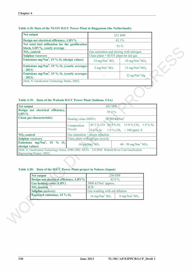
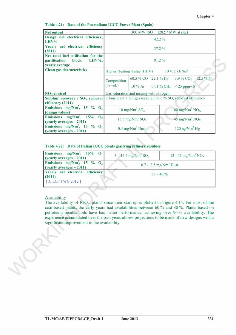
Table 4.17 to Table 4.22 give emission levels and energy efficiencies achieved by IGCC plants fitted with the techniques described in the aforementioned ‘description’ section.
Table 4.17: Data of the Tampa IGCC Power Plant (Florida, USA)
Net output 250 MW Design net efficiency, LHV% 41.2 % Clean gas characteristics Heating value (HHV) 9 932 kJ/Nm3
42.8 % CO 38.4 % H2 14.5 % CO2 3.3 % N2Composition (%vol)
0.9 % Ar 0.1 % CH4 200 ppmv S NOX control Waste N2 to combustion chamber Sulphur recovery 98 % sulphuric acid production plant Emissions mg/Nm3, 6% O2(design values)
40 mg/Nm3 SO2 100 - 125 mg/Nm3 NOX
[Holt, N. Gasification Technology Status, EPRI 2002. Tampa US DOE, Electric IGCC Project, update 2000]
WORKIN
G DRAFT IN
PROGRESS
Chapter 4
330 June 2013 TL/MC/AP/EIPPCB/LCP_Draft 1
Table 4.18: Data of the NUON IGCC Power Plant in Buggenum (the Netherlands)
Net output 253 MW Design net electrical efficiency, LHV% 43.1% Net total fuel utilisation for the gasifiication block, LHV%, yearly average 92 %
NOX control Gas saturation and mixing with nitrogen Sulphur recovery Claus plant + SCOT plant for tail gas Emissions mg/Nm3, 15 % O2 (design values) 14 mg/Nm3 SO2 10 mg/Nm3 NOX
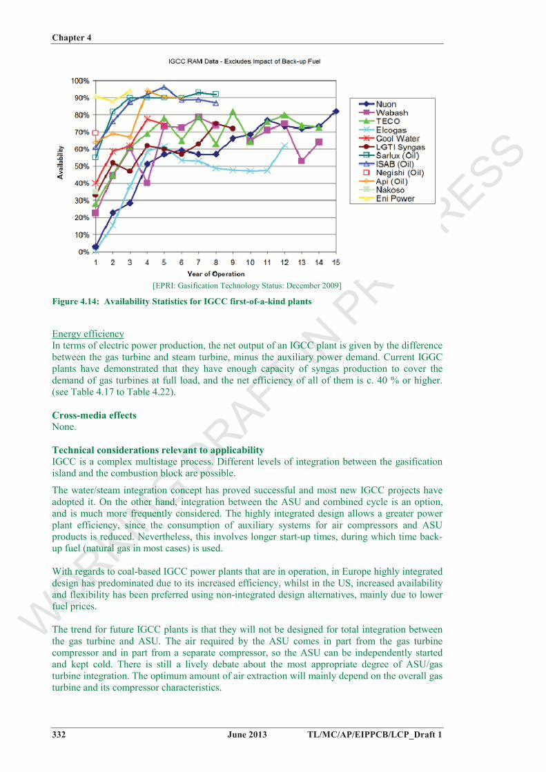
Availability The availability of IGCC plants since their start up is plotted in Figure 4.14. For most of the coal-based plants, the early years had availabilities between 60 % and 80 %. Plants based on petroleum residual oils have had better performance, achieving over 90 % availability. The experience accumulated over the past years allows projections to be made of new designs with a significant improvement in the availability.
WORKIN
G DRAFT IN
PROGRESS
Chapter 4
332 June 2013 TL/MC/AP/EIPPCB/LCP_Draft 1
[EPRI: Gasification Technology Status: December 2009]
Figure 4.14: Availability Statistics for IGCC first-of-a-kind plants
Energy efficiencyIn terms of electric power production, the net output of an IGCC plant is given by the difference between the gas turbine and steam turbine, minus the auxiliary power demand. Current IGGC plants have demonstrated that they have enough capacity of syngas production to cover the demand of gas turbines at full load, and the net efficiency of all of them is c. 40 % or higher. (see Table 4.17 to Table 4.22).
Cross-media effects None.
Technical considerations relevant to applicability IGCC is a complex multistage process. Different levels of integration between the gasification island and the combustion block are possible.
The water/steam integration concept has proved successful and most new IGCC projects have adopted it. On the other hand, integration between the ASU and combined cycle is an option, and is much more frequently considered. The highly integrated design allows a greater power plant efficiency, since the consumption of auxiliary systems for air compressors and ASU products is reduced. Nevertheless, this involves longer start-up times, during which time back-up fuel (natural gas in most cases) is used.
With regards to coal-based IGCC power plants that are in operation, in Europe highly integrated design has predominated due to its increased efficiency, whilst in the US, increased availability and flexibility has been preferred using non-integrated design alternatives, mainly due to lower fuel prices.
The trend for future IGCC plants is that they will not be designed for total integration between the gas turbine and ASU. The air required by the ASU comes in part from the gas turbine compressor and in part from a separate compressor, so the ASU can be independently started and kept cold. There is still a lively debate about the most appropriate degree of ASU/gas turbine integration. The optimum amount of air extraction will mainly depend on the overall gas turbine and its compressor characteristics.
WORKIN
G DRAFT IN
PROGRESS
Chapter 4
TL/MC/AP/EIPPCB/LCP_Draft 1 June 2013 333
Regarding pollutant abatement techniques, they are all generally applicable. The selected techniques depend on the plant configuration and on the raw syngas characteristics.
Economics Capital costs are higher, when compared with combined cycles that use natural gas, with fabrication, cleaning and transport, or with combustion boilers with cleaning of the exhaust. In general, IGCC investment is expected to be higher than for a PC hard-coal plant without CCS, but investment for IGCC+CCS is expected to be smaller than for PC+CCS.
Investment is estimated at between EUR 1 and 1.5 million/MWth (demonstration plant). A study by the International Energy Agency considers that the specific investment for IGCC is about 20 % higher than for pulverised-coal combustion. However, there is more uncertainty in IGCC costs as there are no recently built coal IGCC plants and the existing ones were constructed as demonstration plants. Suppliers have plans to bring the capital costs to within 10 % of that of pulverised-coal combustion. The challenges are reliability, availability, and investment. IGCC technologies could be commercially available around 2020 with CCS. Note to the TWG: please provide additional info on the economics of the pollutant abatement techniques [ 36, EGTEI 2012 ] [ 37, EGTEI 2012 ]
Driving forces High fuel flexibility. High overall efficiency and very low emissions across all pollutants. CO2 capture solution associated to IGCC seems an interesting concept. Higher degree of public acceptance than for pulverised-coal fired units.
Example plants Coal/water slurry-fed IGCC plantsPolk IGCC power plant, Tampa, Florida, USA (55 % petroleum coke/45 % coal) Wabash River IGCC Repowering project, USA (petroleum coke)
Dry fed coalNuon IGCC power plant, the Netherlands Elcogas IGCC plant in Puertollano, Spain (50/50 mixture of coal and petroleum coke) Schwarze Pumpe, germany
Dry fed, enriched air blownIGCC project in Nakoso, Japan Note to the sugbgroup: Additional information needed about this (still?) project
Heavy oil gasificationIsab Energy S.r.l., Italy Api Energia, Falconara, Sarlux, Sardinia Nigishi, Japan PERNIS, Netherlands, Eni, Sannazzaro- Ferrera Erbognone, Italy Fuijan Refinery Ethylene project
4.3.1.2 Reduction of emissions from a gasifier connected to an existing coal boiler
Description Partial replacement of coal by syngas from biomass and/or other feedstocks, with or without previous syngas cleaning, enables the environmental profile of coal-fired boilers to be improved.
Technical description The gasifier is connected to an existing coal boiler, either directly (see Figure 4.15) or with intermediate syngas cleaning steps (see Figure 4.16). CFB/BFB gasification with dry gas cleaning prior to the boiler (Figure 4.10b – dry cleaning and chlorine removal) makes it possible to utilise high-alkali content biofuels (such as straw), as well as SRF with higher chlorine and heavy metal contents.
The gasifier may utilise different feedstocks (solid biofuels and refuse-derived fuels) from the local area. The feedstock is gasified without drying, and the moisture content can be up to 60 %. The capacity of the gasifier depends on the moisture content and of the heating value of the input fuel. Biofuels and/or other feedstocks are gasified at atmospheric pressure at a temperature of about 850 °C.
SOX emissions decrease due to the lower sulphur content of the syngas replacing coal. NOXemissions decrease as the syngas, having a quite high moisture content due the gasification of biomass, has a cooling effect in the combustion chamber, allowing a reduction in thermal NOXgeneration.
Direct connection gasifier – combustion plantThe hot flue-gas flows through the uniflow cyclone and is slightly cooled down in the air pre-heater, before being fed into the main boiler. Simultaneously, the gasification air is heated up in the air pre-heater before feeding it into the gasifier. The syngas is led directly from the gasifier through the air pre-heater to some boiler burners, which are located below the coal burners in the main boiler. This means that the environmental clean up (air emissions) relies on the main boiler flue-gas cleaning installations. The gas can replace roughly 15 % of the coal consumption. Figure 4.15 presents the configuration of the Finish Lahti plant.
Connection gasifier – combustion via dry syngas cleaningThe developed method is based on gas filtration at 200 – 450 oC temperature in a bag filter unit. With solid refuse derived fuels (SRF) and other fuels containing a lot of plastic material, the filtration temperature has to be higher than 350 °C, in order to avoid tar condensation problems [Wilén et al., 2004]. Ceramic filter bags are used. Calcium hydroxide or other alkali sorbents are injected into the gas before the filter unit, if necessary, to improve chlorine capture. However, the inherent fuel alkali metals and the calcium-based bed material also react efficiently with HCl during gas cooling and, especially, in the filter cake. Figure 4.16 shows the configuration of the Finish Vaskiluoto plant.
WORKIN
G DRAFT IN
PROGRESS
Chapter 4
TL/MC/AP/EIPPCB/LCP_Draft 1 June 2013 335
Figure 4.15: Lahti CFB Gasifier
Figure 4.16: Vaskiluoto gasification plant
Achieved environmental benefits Reduction of SO2, NOx, particulate and metal emissions to air. The multi-fuel firing of syngas and coal enables utilisation of an efficient large-scale steam cycle, which results in a high power production efficiency. Possible valorisation of challenging fuels, when using syngas treatment techniques. Reduced emissions of HCl and metals, when using syngas treatment techniques.
Environmental performance and operational data The gasification of varying fuel mixes (biomass, SRF, plastic, paper, railway sleepers, shredded tires) is possible, and with high availabilities (e.g. 96 % availability achieved by the Lahti gasifier, Finland). [Palonen et al., 2005; Palonen & Nieminem, 2001 - Available from: http://www.fwc.com/publications/tech_papers/files/TP_GASFY_04_02.pdf].
Direct connection gasifier – combustion plantA comprehensive one-year monitoring program in 1998 studying changes in the main boiler emissions from the Lahti gasifier (Finland) demonstrated significantly decreased emissions of CO2, NOx, SOx and particulates from the coal-fired boiler, while the emissions of HCl and some metals increased depending on the quality of the gasified waste when the plant was gasifying 40 % waste and 60 % biofuels. Boiler flue-gas emission measurements from co-firing of syngas
WORKIN
G DRAFT IN
PROGRESS
Chapter 4
336 June 2013 TL/MC/AP/EIPPCB/LCP_Draft 1
and coal in 2001 confirmed these effects [Wilén et al., 2004] (see Table 4.6). While no changes were found in the emissions of CO, dioxins, furans, PAH, benzenes and phenols during monitoring in 1998 [Palonen et al., 2005, Palonen & Nieminen, 2001], the 2001 measurements indicated a slight increase in the boiler flue-gas emissions of total PAH-compounds, polychlorinates benzenes, and polychlorinated biphenyls, while the emissions of chlorophenols and dioxins decreased, as compared to coal-alone combustion data from 1997 [Wilén et al., 2004].
The most probable reason for the decrease in dust content in the flue-gas is the increase in the flue-gas moisture content, which enhance the operation of the ESP. The reasons for the decrease in NOX emissions are first, the reburning effect of ammonia and, second (far more importantly), the cooling effect of the low calorific, high moisture syngas in the bottom part of the boiler.
Because of the extremely low sulphur content of biofuels, the main boiler SOX emissions decrease, while in contrast, the HCl content of flue-gas increases, because of the higher chlorine content in SRF fuel and shredded tires in the gasifier, compared to the low-chlorine coal in the main boiler [Palonen & Nieminen, 2001]. With regards to the metal stack emissions, increases in some elements (e.g. Hg) can be seen, but because of the very low base levels in coal combustion, the changes that were measured were in practice very small.
Gasifier – combustion plant connection via syngas treatment techniquesIn the case of waste-derived fuels, all heavy metals except mercury can be removed with over 99 % efficiency by filtration [Wilén et al., 2004]. However, final flue-gas cleaning after the boiler may be necessary, in order to fulfil the emission requirements, especially with mercury-containing waste-fuels.
ResiduesThe only residue from the gasifier is bottom ash. In the case of the Lahti gasifier (Finland), this consists mainly of sand and limestone. Furthermore, small amounts of solid impurities, such as pieces of metal, concrete and glass may be found in the bottom ash if waste is co-gasified. Typically, the carbon content in the bottom ash is less than 0.5 %. No signs of chlorine are detected [Niemen, Kurkela and Palonen, 2004]. When shredded tires are used as a fuel in the gasifier, the zinc content in the gasifier bottom ash increases from a few hundred ppm to 3000 ppm. All other analysed elements are in the range of a few or tens of ppms (As, Cd, Ni, Pb and Hg), or in the range of hundreds of ppms (Cr, Cu) [Palonen & Nieminen, 2001].
In the case of direct connection of the gasifier to the boiler, the share of the gasifier fly-ash of the main coal-boiler total filter ash is small, only 3 to 5 %, and hence changes in the main boiler filter ash quality caused by the gasifier are very small, even in the case of waste co-gasification [Palonen & Nieminen, 2001]. The biggest change is seen in the zinc content when shredded tires are used as fuel in the gasifier [Palonen & Nieminen, 2001].
In case of syngas pretreatment, a dry filter dust is produced, in addition to bottom ash from the gasifier. The filter dust contains unconverted carbon (char), the finest fraction of the bed material, inert matter of the feedstock, and chlorine removal sorbent.
Cross-media effects Depending on the gasified feedstock (e.g. if waste is co-gasified with biomass), some pollutants such as HCl and metal emissions may be increased in emissions to air. For instance, the use of contaminated materials (e.g. gluelam containing nitrogen and sodium in glue) increases the concentration of ammonia, hydrogen cyanide and alkalies in the syngas [Palonen & Nieminen, 2001].
Technical considerations relevant to applicability The most simple process configuration without gas cleaning (see Figure 4.10a – raw gas (clean fuel)) is suitable for feedstocks which do not contain significant amounts of alkali and metals or
WORKIN
G DRAFT IN
PROGRESS
Chapter 4
TL/MC/AP/EIPPCB/LCP_Draft 1 June 2013 337
chlorine, as in this process a relatively large part of the biomass ash is led together with the product gas into the coal boiler. Such feedstock are e.g. wood chips, sawdust and bark, forest residue chips and some clean plastic or paper wastes. This technology is available as a commercial technology.
Due to the effective removal of chlorine, alkali metals and heavy metals, the configuration with dry syngas pretreatment can also be applied for many challenging biomasses and waste-derived fuels. For example straw, energy crops and different agricultural residues are fuels which often require gas cleaning to lower the alkali and chlorine content before combustion in a boiler, which involves high steam temperatures.
Economics The gasifier - PC boiler process connection offers low investment and operation costs, thanks to the utilisation of existing power plant capacity, with only small modifications to the main boiler.
Total costs of the 60 MWth gasification plant at the Kymijärvi power plant were about EUR 12 million, including the fuel preparation plant, civil works, instrumentation and control, as well as electrification works.
Driving forces Replacement of coal by almost CO2-neutral biomass-derived gas reduces fossil-fuel CO2emissions. In PC-boilers, the multi-fuel firing of gas with coal is significantly simpler than the multi-fuel firing of solid biomass with coal.
Example plants A pioneering plant for the configuration without gas cleaning has been in successful operation in Lahti, Finland (example Kymijarvi) since 1998. There the product gas from a 60 MWthgasifier replaces 15 % of the coal input in a PC-boiler. A larger unit of 140 MWth was recently put into operation in Vaasa (Finland) for replacing about 25 % of coal in a PC boiler.
The first industrial gasification plant based on the dry syngas treatment was put into commercial operation in 2012 at Lahti Finland (Lahti II gasification plant with 2 x 80 MW gasification connected to a separate gas-fired boiler). Source-separated industrial and household wastes and demolition wood are used as the feedstock at this plant. Another such example plant is the Finish Vaskiluoto gasification plant.
Other plants:Coronso Oy, Varkhaus, Finland Electrabel, Ruien, Belgium Essent, Amercentrale, Netherlands Biococomb, Austria
Reference litterature[Kurkela, 2002 Available from: http://www.ieatask33.org/app/webroot/files/file/publications/OPETReport4gasification.pdf; Wilén et al., 2004]
4.3.1.3 Biomass gasification connected to engine plants with prior wet gas cleaning
Technical description Gasification with wet gas cleaning (Figure 4.10c – wet cleaning) is a process which can produce a very clean gas for subsequent use in e.g. gas engines. However, it produces a waste water stream, and this waste water treatment may be difficult to design in an environmentally fully acceptable manner [Wilén et al., 2004]. Problematic substances in the waste water from the gas
WORKIN
G DRAFT IN
PROGRESS
Chapter 4
338 June 2013 TL/MC/AP/EIPPCB/LCP_Draft 1
scrubber, which may be difficult to handle/eliminate, include benzene, naphthalene, PAHs and phenol. [Waste Water Discharge Permission for Skive CHP, Skive Municipality, 2005]
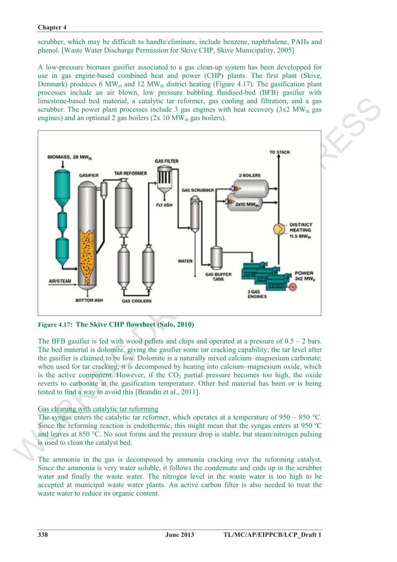
A low-pressure biomass gasifier associated to a gas clean-up system has been developped for use in gas engine-based combined heat and power (CHP) plants. The first plant (Skive, Denmark) produces 6 MWel and 12 MWth district heating (Figure 4.17). The gasification plant processes include an air blown, low pressure bubbling fluidised-bed (BFB) gasifier with limestone-based bed material, a catalytic tar reformer, gas cooling and filtration, and a gas scrubber. The power plant processes include 3 gas engines with heat recovery (3x2 MWth gas engines) and an optional 2 gas boilers (2x 10 MWth gas boilers).
Figure 4.17: The Skive CHP flowsheet (Salo, 2010)
The BFB gasifier is fed with wood pellets and chips and operated at a pressure of 0.5 – 2 bars. The bed material is dolomite, giving the gasifier some tar cracking capability; the tar level after the gasifier is claimed to be low. Dolomite is a naturally mixed calcium–magnesium carbonate; when used for tar cracking, it is decomposed by heating into calcium–magnesium oxide, which is the active component. However, if the CO2 partial pressure becomes too high, the oxide reverts to carbonate at the gasification temperature. Other bed material has been or is being tested to find a way to avoid this [Brandin et al., 2011].
Gas cleaning with catalytic tar reformingThe syngas enters the catalytic tar reformer, which operates at a temperature of 950 – 850 °C. Since the reforming reaction is endothermic, this might mean that the syngas enters at 950 °C and leaves at 850 °C. No soot forms and the pressure drop is stable, but steam/nitrogen pulsing is used to clean the catalyst bed.
The ammonia in the gas is decomposed by ammonia cracking over the reforming catalyst. Since the ammonia is very water soluble, it follows the condensate and ends up in the scrubber water and finally the waste water. The nitrogen level in the waste water is too high to be accepted at municipal waste water plants. An active carbon filter is also needed to treat the waste water to reduce its organic content.
WORKIN
G DRAFT IN
PROGRESS
Chapter 4
TL/MC/AP/EIPPCB/LCP_Draft 1 June 2013 339
Achieved environmental benefits High energy efficiency; high electrical efficiency of gas engines, even at small sizes. [Brandin et al., 2011]. Overall air emission levels: according to the Environmental Approval for Skive CHP (Skive Municipality, 2005), the most important air emissions from the gas engines are NOX, unburnt hydrocarbons, CO, and formaldehyde, and, besides from CO, the emission limit values by legislation are the same as for natural gas-fired engines.
Environmental performance and operational data Such a gasification plant, when fully automated, can use all combinations of gas consumers (gas engines and gas boilers), ensuring a large flexibility.
Achieved efficiencies at Skive CHP (Skive Fjernvarme, 2012) are:
total fuel utilisation: 86 %; electrical efficiency: 30 %; thermal efficiency (heat for district heating): 56 %.
The initial tar conversion over the catalyst was 90 %, but decreased to 70 %. However, no heavy tars were found after the reformer completed 7500 hours of operation. The ammonia conversion over the catalyst is low, and a maximum of 60 % is obtained.
The environmental performance (emissions and consumption levels) per MWh production (heat and electricity) through the years 2007 – 2012 are given in Table 4.7 and Table 4.16.
Cross-media effects Waste water produced from the gas scrubber contains sludge, organic compounds, and inorganic species. At the Skive plant, this is handled by a combination of mechanical treatment, active carbon filtering for removal of CxHy, and pH-neutralisation by NaOH and CH2O2 before the waste water from the scrubber is discharged to the municipal waste water plant. According to the waste water discharge permit for Skive CHP (Skive Municipality, 2005), there are potentially 4 problematic substances in the waste water from the gas scrubber which may compromise the water quality of the recipient, these are: benzene, naphthalene, PAHs and phenol.
Ammonia content of the condensate has also been mentioned as a problem, given the emission regulation at the municipal water treatment plant at the Skive plant, despite the catalytic reforming step for the tars [Brandin et al., 2011].
Another drawback of the system is the gas engine exposure to corrosive combustion products, resulting in short and expensive maintenance intervals [Brandin et al., 2011].
Technical considerations relevant to applicability Note to the TWG: provide additional info
Economics Investment costs are roughly 50 % higher than in the dry gas cleaning or directly connected options [Wilén et al., 2004]
Driving forces High electrical efficiencies of gas engines, even at small sizes, low cost, and reliability; it also works well even at low loads [Brandin et al., 2011].
Example plants Skive CHP, Denmark Varnamo IGCC, Sweden
WORKIN
G DRAFT IN
PROGRESS
Chapter 4
340 June 2013 TL/MC/AP/EIPPCB/LCP_Draft 1
Reference litterature
4.3.2 Techniques for the prevention and control of water pollution from the gasification process
Note to the TWG: Please provide additional information (see below topics lacking of information)
Description Waste water is recirculated after internal treatment for IGCC plants and gasification plants using syngas wet cleaning techniques.
Technical description Gasification plants may use water scrubbing for removing pollutants from the syngas, such as chlorides and other halides, ammonia or particulates. The generated stream is sent to the water treatment unit prior to recirculation. Dissolved gases such as H2S, NH3 and CO2 are stripped out. Because the water is re-used for moisturising the syngas before being combusted in gas turbines or engines, the salt content of the water should be low. The water is evaporated to remove the salts (mainly NaCl) and the condensate is also treated in a dedicated demineralisation plant to achieve a low salt content (Cl < 0.05 mg/l).
Achieved environmental benefit Reduced overall emissions to water. Reduced water consumption.
Environmental performance and operational data
Cross-media effects
Technical considerations relevant to applicability
Economics
Driving forces Zero-discharge in the environmental permit.
Example plants Nuon, Elcogas, Tampa
Reference litterature
4.3.3 Techniques for the handling of residues and by-products from the gasification process
Note to the TWG: Please provide additional information (see below topics lacking of information)
Description Residues and by-product reuse.
Technical description The bottom ashes from gasification may either be removed dry, or as slag if the gasifier operating temperature is well above the ash fusion temperature, which is often the case in e.g. entrained-flow gasifiers. The gasifier slag is separated in a molten state through the bottom of
WORKIN
G DRAFT IN
PROGRESS
Chapter 4
TL/MC/AP/EIPPCB/LCP_Draft 1 June 2013 341
the gasifier, cooled in a bath of water and extracted using lock hoppers. Slag can be removed continuously from the slag bath at the base of the gasifier via a letdown system, which seems to show benefits in relation to lock hopper systems. The quality – and hence the reuse potential – of the gasification slags may be better than for the corresponding combustion ashes due to their glassy and chemically stable form .
Sour gas is converted to solid sulphur in a Claus unit, and tail gas from the Claus unit is hydrogenated before being recycled to the COS hydrolysis unit, allowing recovery of 98 % of the total fuel sulphur content as elemental sulphur. Sulphur can also be recovered as gypsum, e.g. by washing with a limestone solution. The plant flowsheet includes a syngas cooler, hot gas filter and cold gas cleanup using COS hydrolysis and MDEA for H2S removal. The H2S rich gas is burnt and the flue gases scrubbed with limestone slurry to produce gypsum for sale. This technique has been developped where there is very little market for elemental sulphur, like in Japan.
Depending on the market situation, slag and recovered sulphur are likely to be traded. The slag can be used in e.g. the manufacturing of flooring tiles, and sulphur can be used in the manufacture of fertilisers and sulphuric acid.
For the fly ashes, the quality and reuse potential may vary significantly, depending on both the syngas cleaning technology used, the gasification technology, and the quality of the original feedstock. In some cases, the fly ash will have a good quality and will not contain sorbents, and these fly ashes may be marketed (example plants: Nuon and Elcogas IGCC).
Achieved environmental benefits Reduced transfer of pollutants to the environement.
Environmental performance and operational data See Section 4.2.1.
Cross-media effects Slag may contain a fraction of the intermediate size with a high ash content, which makes its sale difficult.
Technical considerations relevant to applicability Filter dust from syngas filtration may contain a mixture of sorbents, unreacted carbon, and all the impurities of the original feedstock, and disposal may be the only option. The final disposal methods of the filter dust must be designed on case-by-case basis, depending on the original feedstock composition.
Economics
Driving forces
Example plants Tampa (US). Nuon (the Netherlands): Wabash River (propietary slag removing system USA) Nakoso (Japon) Elcogas (Spain) Reference litterature
4.3.4 Techniques to increase the energy efficiency of the gasification process
WORKIN
G DRAFT IN
PROGRESS
Chapter 4
342 June 2013 TL/MC/AP/EIPPCB/LCP_Draft 1
4.3.4.1 High temperature and pressure gasification Note to the TWG: Please provide additional information (see below topics lacking of information)
Description The use of a gasification technique with high temperature and pressure operating paramaters enables achieving the maximum carbon conversion rate.
Technical description The use of a gasification technique with high temperature and pressure operating paramaters enables achieving the maximum carbon conversion rate.
Achieved environmental benefit Reduced fuel consumption and increased energy efficiency.
Environmental performance and operational data In Elcogas (Spain), the gasification reaction takes place in the gasifier combustion chamber at a high temperature, between 1600 and 1800 °C, and at a high pressure of 24 bar, enabling a carbon conversion for the gasification of more than 98 %.
In Nakoso (Japan), a low syngas temperature of approximately 1100 ºC, simplifies the cooling system but means a lower conversion rate.
Technical considerations relevant to applicability
Cross-media effects
Economics Pressurised systems significantly reduce the costs of syngas clean-up and overall capital costs. Capital costs decrease largely due to the decreasing gas volume in the cleaning section. The extra costs for air or oxygen compression are more than outweighed by smaller syngas clean-up equipment and reduced compression costs downstream, and hence pressurised systems have a lower total capital cost than atmospheric systems [E4tech, 2009].
Driving forces
Example plants Elcogas (Spain), Nakoso (Japan).
Reference litterature
4.3.4.2 Dry feedstock feeding system Note to the TWG: Please provide additional information (see below topics lacking of information)
Description The use of a dry system for feeding the fuel to the gasifier enables improvements in the energy efficiency of the gasification process.
Technical description In entrained-flow gasification of coal, the fine coal can be fed to the gasifier in either a dry or slurry form. The former uses a lock hopper system, while the latter relies on the use of high-pressure slurry pumps. The slurry feed is a simpler operation, but it introduces water into the reactor which needs to be evaporated. The result of this additional water is a syngas product with higher H2 to CO ratio, but with a lower gasifier thermal efficiency. The feed preparation system needs to be evaluated, along with other process design alternatives.
WORKIN
G DRAFT IN
PROGRESS
Chapter 4
TL/MC/AP/EIPPCB/LCP_Draft 1 June 2013 343
Achieved environmental benefit Reduced energy consumption and increased energy efficiency.
Environmental performance and operational data In Nuon (the Netherlands), the cooled syngas heating value typically contains ~80% of the heating value of the coal feed. This is higher than that achievable with the coal/water slurry fed systems.
Technical considerations relevant to applicability
Cross-media effects
Economics
Driving forces
Example plants Nuon (The Netherlands).
Reference litterature
4.3.4.3 Use of recovered heat from the gasification process Note to the TWG: Please provide additional information (see below topics lacking of information)
Description The heat recovered from syngas cooling is reused internally to dry the fuel or produce additional heat/power in order to reduce heat losses and to improve the process energy efficiency.
Technical description The heat recovered from syngas cooling is reused internally to dry the fuel or produce additional heat/power, in order to reduce heat losses and to improve the process energy efficiency.
For instance, biomass gasification systems are differentiated from combustion systems by the need for some systems (but not all) to dry the biomass prior to feeding into the gasifier. The general requirements for the moisture content in biomass is < 20 % moisture. However, some systems can handle wet biomass with up to 60 % moisture (e.g. at Kymijarvi, Lahti, Finland). A variety of drying methods, including fluidised-bed and rotary mechanisms, direct exposure to flue-gas, or a thermal fluid, exist [Pytlar, 2010]. In order to avoid losing the energy used to drive off water, heat recapture is favoured.
Achieved environmental benefit Reduced energy consumption and increased energy efficiency.
Environmental performance and operational data In Elcogas (Spain), the raw syngas is quenched with recycled syngas to a temperature of 800 °C upon leaving the combustion chamber. The syngas is then cooled in two water-tube boilers down to 250 °C, generating a HP and IP steam that is superheated in the HRSG of the power block and sent to the steam turbine. The recovered energy enables improving the energy efficiency of the gasification process from 74.1 % to 91.2 % (yearly average).
In Nuon (The Netherlands), the raw syngas is quenched with recycled syngas to a temperature of 800 °C upon leaving the gasifier reactor. The syngas is then cooled in a syngas cooler down to 235 °C, generating HP and IP steam (that is superheated in the HRSG of the power block and sent to the steam turbine) and LP steam for gasification and gas cleaning. The recovered energy
WORKIN
G DRAFT IN
PROGRESS
Chapter 4
344 June 2013 TL/MC/AP/EIPPCB/LCP_Draft 1
enables improving the energy efficiency of the gasification process from 77.1 % to 92 % (yearly average).
Technical considerations relevant to applicability
Cross-media effects
Economics
Driving forces
Example plants Elcogas (Spain), Nuon (The Netherlands).
Reference litterature
4.3.4.4 Full integration of the air supply unit (ASU) with the gas turbine in IGCC plants
Note to the TWG: Please provide additional information (see below topics lacking of information)
Description The air separation unit (ASU) and the gas turbine are fully integrated, meaning that all the air feed for the ASU is supplied (extracted) from the gas turbine compressor.
Technical description The air separation unit (ASU) and the gas turbine are fully integrated, meaning that all the air feed for the ASU is supplied (extracted) from the gas turbine compressor.
Achieved environmental benefit Increased energy efficiency.
Environmental performance and operational data
Technical considerations relevant to applicability