Serial Number Purchase Date Questions, problems, missing parts? Before returning to your retailer, call our customer service department at 1-800-584-8089, 7:30 a.m. - 5:00 p.m., EST, Monday - Friday. ATTACH YOUR RECEIPT HERE 4 IN. SUBMERSIBLE WELL PUMP 3 WIRE MODELS: #1450-0009, 1451-0006, 1452-0005, 1452-0007 Zoeller ® is a registered trademark of Zoeller Co. All Rights Reserved. 025096 B Español p. 25
Transcript
Validation code: LB659498
Serial Number Purchase Date
Questions, problems, missing parts? Before returning to your retailer, call our customer service department at 1-800-584-8089, 7:30 a.m. - 5:00 p.m., EST, Monday - Friday.
ATTACH YOUR RECEIPT HERE
4 IN. SUBMERSIBLE WELL PUMP 3 WIRE MODELS: #1450-0009, 1451-0006,
1452-0005, 1452-0007
Zoeller® is a registered trademark of Zoeller Co. All Rights Reserved.
025096 B
Español p. 25
2
PRODUCT SPECIFICATIONS
Pump Performance Chart
ITEM # HP GPMPUMPING DEPTH IN FEET - CAPACITIES IN GALLONS PER
MINUTE AT 40 PSI (PRESSURE PER SQUARE INCH)20 40 60 80 100 125 150 175 200 250 300 325
NOTE: Pump capacity in GPM should equal the total number of water fixtures in the home. If you have 3 bathroom fixtures x 2 bathrooms, plus 3 fixtures in the kitchen and 1 outside fixture, the total fixture count is 10. Your pump should provide 10 GPM per the chart above. Typical 3 - 4 bedroom homes require 8 - 12 GPM.
Please read and understand this entire manual before attempting to assemble, operate or install the product. • NOTE: Pumps with the “UL” Mark and pumps with the “US” mark are tested to UL Standard
UL778.CSA certified pumps are certified to CSA Standard C22.2 No. 108. (CUS)
ELECTRICAL SHOCK HAZARDAlways disconnect power source before performing any work on or near the motor or its connected load. If the power disconnect point is out-of-sight, lock it in the open position and tag it to prevent unexpected application of power. Failure to do so could result in fatal electrical shock.ELECTRICAL SHOCK HAZARDDo not handle the pump with wet hands or when standing in water as fatal electrical shock could occur. Disconnect main power before handling unit for ANY REASON!RISK OF ELECTRIC SHOCKThese pumps have not been investigated for use in swimming pool areas.ELECTRICAL SHOCK HAZARDCan shock, burn or cause death. Ground pump before connecting to power supply.ELECTRICAL SHOCK HAZARDThe pump is intended for use in a well. Motor frame must be connected to power supply ground or fatal electrical shock may result.ELECTRICAL SHOCK HAZARDNEVER leave fused disconnect switch or pressure control switch cover or covers open (either partially or completely) when not being worked on by a qualified electrician or repairman.
SAFETY INFORMATION
DANGER
3
WARNINGELECTRICAL SHOCK ALERTFollow all local electrical and safety codes, as well as the National Electrical Code (NEC) and the Occupational Safety and Health Act (OSHA).ELECTRICAL SHOCK ALERTAll electrical wiring or service should be done by a qualified electrician.EXPLOSION ALERTDo not use to pump flammable or explosive fluids such as gasoline, fuel oil, kerosene, etc. Do not use in flammable and/or explosive atmospheres.HAZARDOUS PRESSURE ALERTInstall pressure relief valve in discharge pipe. Release all pressure on system before working on any component.CHEMICAL ALERT.Prop65 Warning for California residents:
WARNING: Cancer and Reproductive Harm - www.P65Warnings.ca.gov
CAUTION
ELECTRICAL SHOCK MAY OCCURWire motor for correct voltage. See Electrical section and motor nameplate.ELECTRICAL SHOCK MAY OCCURGround motor and controls before connecting to power supply.ELECTRICAL SHOCK MAY OCCURFollow wiring instructions in this manual when connecting to power lines.ELECTRICAL SHOCK MAY OCCURProtect power cable from nicks or cuts from sharp objects or scraping on well casing when lowering pump into well. Do not allow it to come into contact with oil, grease, hot surfaces or chemicals.ELECTRICAL SHOCK MAY OCCURThe motor voltage and phase indicated on the motor nameplate should be checked against the actual electrical supply. Check your power source. Check electrical supply for correct fusing, wire size, and adequate grounding and transformer size.PRODUCT DAMAGE MAY OCCURThe power supply for a submersible pump should be a separate circuit, independent of all other circuits. It must be equipped with a fuse box of ample capacity.PRODUCT DAMAGE MAY OCCURShut off power source when voltage drops 10% below rated voltage of motor.FIRE SAFETYFor fire protection, power supply should be free of any building, preferably on a direct line from transformer. In event of fire, wires will not be destroyed and water supply not cut-off.
NOTE: Install all electrical equipment in protected area to provide adequate ventilation for pressure switch and controls to prevent moisture damage to components.NOTE: Install pump, pressure tank, pitless adaptor or well seal in accordance with state and local plumbing codes.
4
PREPARATION
Before beginning installation of product, make sure all parts are present. Compare parts with package contents drawing. If any part is missing or damaged, do not attempt to assemble the product. Contact customer service for replacement parts.
Estimated Installation Time: 2 hours.
Tools Required for Installation: Hacksaw, screwdriver, pliers, pipe vise, pipe wrenches (2), wire cutters, wire strippers/crimpers, adjustable wrench (medium-large), Ohmmeter, propane torch, knife or round file, small weight.Materials Required for Installation: Control box (see chart below), Submersible pump cable, power cable, pressure tank, shrink tube & butt connectors, 1-1/4 in. check valve, torque arrestor, hose clamps, pipe fittings, pitless adaptor or well seal, pressure switch, pressure gauge, pressure relief valve, tank cross, 1/4 in. minimum safety rope, electrical tape,. You will also need either enough 1-1/4 in. Schedule 80 PVC pipe to reach 20 ft. below the static level or 20 ft. below the drawdown level of your well, or coiled poly pipe rated for 160 PSI. Poly pipe cannot be used for installations any deeper than 200 ft.Optional Materials: 1-1/4 in. male barbed adaptor for use with poly pipe, cable guards to protect wire inside the well, thread tape and thread paste.Submersible Pump Cable and Power Cable SelectionCheck cable size against Submersible Wire Size Chart below. Motor and control box voltage must match. Submersible power cable must be UL listed for submersible pump applications. For Canadian installations, type RWU, TWU, SGOW or SWOW power supply cable is recommended. Cable is selected for the maximum pump setting plus the offset distance to the service entrance.IMPORTANT: Use of wire sizes smaller than those specified in the chart will cause low starting voltage, may cause early pump failure and will void the warranty. Larger wire sizes may always be used for better economy of operation. Be sure voltage at pressure switch or fuse is rated for 230V (between the following limits: 207 & 253 volts).NOTE: A small AWG number, i.e. 10 Ga., is larger in diameter than a large AWG number, i.e. 14 Ga.The National Electric Code (NEC 250-43) requires a separate ground wire be run down the well to the submersible pump and connected to all exposed metal parts of the pump and motor. Refer to the most recent National Electric Code (NEC) Article 250 (grounding) for additional information.NOTE: All wiring should be done by a qualified electrician.
* NOTE: Wire length is the total distance from power source to pump depth.
Submersible Cable and Ground Wire Selection
WARNING: Turn off power at the electrical service box before starting installation.Finding the Depth of Your Well:1. Tie a small, heavy weight to the end of a
cord (make sure the cord is at least 350 ft. long). Lower this weight into the well until it reaches the bottom. Take up any slack and mark the string at ground level. Pull the string from the well and measure from the weight to your mark. This is the depth of your well. Subtract 10 ft. from your well depth. See Performance chart on page 2 to be sure pump is rated for this depth. (FIG 1)
1
DrawdownWater Level
10 Ft. Min.
20 Ft.
Top of Well Screen
Bottom of Well
22. Drawdown is the lowest water level in the well after the pump is turned on. If you know the drawdown, the pump can be set 20 feet below this level. However, the bottom of the motor should be at least 10 feet from the top of the well screen. (FIG 2)
CAUTION: If your pump depth is 200 ft. or more, you may want to consider contacting a professional well pump installer. Piping filled with water, along with the weight of the pump, will be very heavy. Be sure to have assistance during pump installation.
6
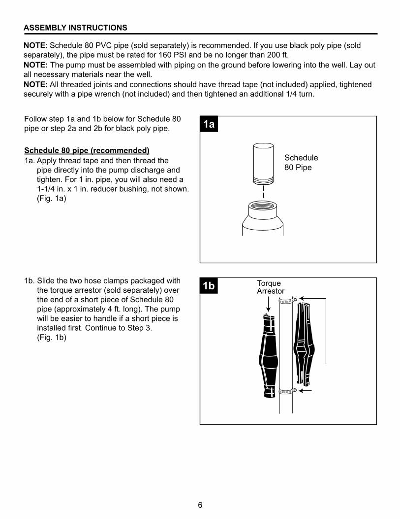
NOTE: Schedule 80 PVC pipe (sold separately) is recommended. If you use black poly pipe (sold separately), the pipe must be rated for 160 PSI and be no longer than 200 ft.NOTE: The pump must be assembled with piping on the ground before lowering into the well. Lay out all necessary materials near the well.NOTE: All threaded joints and connections should have thread tape (not included) applied, tightened securely with a pipe wrench (not included) and then tightened an additional 1/4 turn.
Follow step 1a and 1b below for Schedule 80 pipe or step 2a and 2b for black poly pipe.
Schedule 80 pipe (recommended)1a. Apply thread tape and then thread the
pipe directly into the pump discharge and tighten. For 1 in. pipe, you will also need a 1-1/4 in. x 1 in. reducer bushing, not shown. (Fig. 1a)
Schedule 80 Pipe
Torque Arrestor
1a
1b
ASSEMBLY INSTRUCTIONS
1b. Slide the two hose clamps packaged with the torque arrestor (sold separately) over the end of a short piece of Schedule 80 pipe (approximately 4 ft. long). The pump will be easier to handle if a short piece is installed first. Continue to Step 3. (Fig. 1b)
7
Black poly pipe2a. Apply thread tape and thread a 1-1/4 in.
male barbed adaptor (sold separately) into the top of the pump and tighten. If using 1 in. black poly pipe, install a 1-1/4 in. x 1 in. reducer bushing (sold separately) as shown. (Fig. 2a)
IL1171
1-1/4 in. male barbedadapter
1-1/4 in x 1 in.reducerbushing
2a
IL1172
2b2b. Clamp pipe onto barbed end of male adaptor with two hose clamps (sold separately). (Fig. 2b)
Torque Arrestor
Approx. 4 ft.
33. Firmly clamp the torque arrestor to the pipe approximately 2 to 4 ft. above the pump, using the two clamps provided with the torque arrestor. (Fig. 3)
8
4. Typical installations include the following components. Purchase these items separately depending on your need. (Fig. 4) Discharge pipe - delivers water to homeWell seal or pitless adapter - keeps debris out of wellSafety rope - prevents pump from fallingCheck valve - keeps water in pipeElectrical cable - connects to house electricityTorque arrestor - keeps pump stableDrop pipe - connects pump to dischargeWell casing - holds all components
Discharge Pipe
Spring-Loaded Check Valve (Recommended every 100 ft.)
Safety Rope
Well Seal or Pitless Adapter
Well Casing
Torque ArrestorDrop Pipe
Electrical Cable (Secured to droppipe with tape or clamps every 10 ft.)
4
ELECTRICAL HOOKUP AT THE PUMP
Submersible Cable SplicingPump is equipped with a lead wire assembly with three wires plus the green ground wire. The length of wire needed to attach to this lead wire assembly is equal to the distance from the pump in the well to the top of the well. Additional wire will be needed to run from the top of the well to the house.CAUTION: Follow instructions carefully to make a watertight splice. A leak in the splice can result in pump damage, blown fuses, overload protector tripping or electric shock hazard.
Shrink tube
1Splicing instructions 1. Slide one black shrink tube from a heat
shrink splice kit (sold separately) over each wire (including the green ground wire) coming out of the pump. (Fig 1)
9
Metal Connector
22. NOTE: For each wire coming out of the pump, including the green ground wire, slide the wire from the pump into one end of a metal connector from the splicing kit. Then slide stripped end of wire from electrical cable into other end of metal connector. Connector should be centered over both wires. Squeeze metal connector until it closes tightly over both wire ends. (Fig 2)
IL1145
Shrink tube
Metal Connector33. Slide one shrink tube over each crimped joint. (Fig 3)
ON O
FF
IL1146
44. Hold a torch (not included) approximately 6 in. from the center of the tubing and move it back and forth. Heat one set of wiring tubing at a time until seal is completed. During the heating process, keep all other wires/tubing away from heat to prevent melting together. Avoid overheating, as this may make the tubing brittle. When liquid oozes from end of tube, seal should be complete. (Fig 4)
CAUTION: Do not lift pump by power cable or motor leads! Damage to cable or leads will result.
10
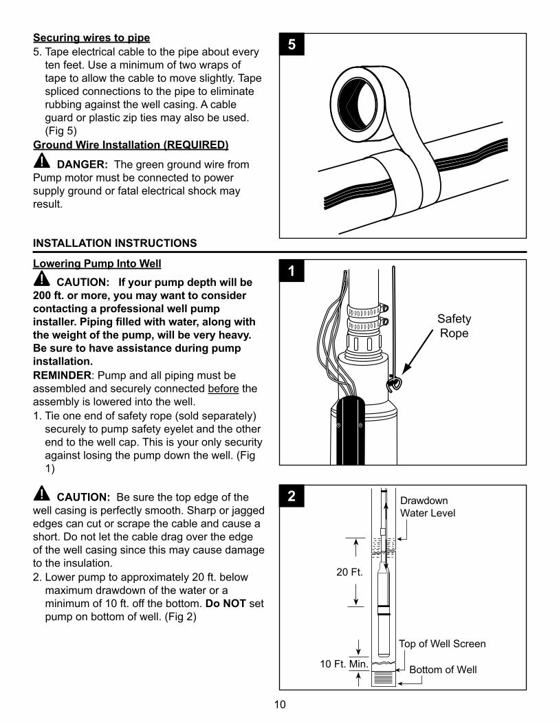
5Securing wires to pipe5. Tape electrical cable to the pipe about every
ten feet. Use a minimum of two wraps of tape to allow the cable to move slightly. Tape spliced connections to the pipe to eliminate rubbing against the well casing. A cable guard or plastic zip ties may also be used. (Fig 5)
Ground Wire Installation (REQUIRED)
DANGER: The green ground wire from Pump motor must be connected to power supply ground or fatal electrical shock may result.
INSTALLATION INSTRUCTIONS
Lowering Pump Into Well CAUTION: If your pump depth will be
200 ft. or more, you may want to consider contacting a professional well pump installer. Piping filled with water, along with the weight of the pump, will be very heavy. Be sure to have assistance during pump installation.REMINDER: Pump and all piping must be assembled and securely connected before the assembly is lowered into the well. 1. Tie one end of safety rope (sold separately)
securely to pump safety eyelet and the other end to the well cap. This is your only security against losing the pump down the well. (Fig 1)
CAUTION: Be sure the top edge of the well casing is perfectly smooth. Sharp or jagged edges can cut or scrape the cable and cause a short. Do not let the cable drag over the edge of the well casing since this may cause damage to the insulation.2. Lower pump to approximately 20 ft. below
maximum drawdown of the water or a minimum of 10 ft. off the bottom. Do NOT set pump on bottom of well. (Fig 2)
SafetyRope
DrawdownWater Level
10 Ft. Min.
20 Ft.
Top of Well Screen
Bottom of Well
1
2
11
3. Use a pipe vise (not included) to prevent the pump and pipe from dropping into the well. (Fig 3)
3
4. Add a well seal or pitless adaptor (sold separately) to allow for the pipe to be connected to house service.
Instalación de un adaptador desmontable
por debajo de la línea
de congelación
Instalación de un sello para pozos en la parte superior del entubado del pozo
O
4
IL1148
4a4a. Pitless Adaptor Installation. Pitless adaptor should be installed below the frost line, and on the side of the well casing where the supply line will run from well, in accordance with the manufacturer’s instructions.
NOTE: Pitless adaptor models vary according to each application. (Fig. 4a)
12
4b4b. Well Seal Installation: After the pump assembly is lowered into the well, mount the well seal onto the well casing and tighten the four bolts in the well seal evenly.
PRELIMINARY TEST RUN
Fuse Box
OutsideFaucet
Pump inWell
OutsideFaucet
Pump inWell
WARNING: All electrical wiring or service should be done by qualified electrician. Be sure to test cable for continuity with an ohmmeter before starting the pump.1. All wells should be flushed clear before
allowing water into the house. (Fig. 1)
2. Open an outside faucet and allow water to run until water is clear of sand or any other impurities. If an outside faucet is not available, place softener in bypass position, remove aerator from a high-flow faucet and allow water to run until it is clear of impurities. Once clear, turn off water flow, replace aerator and put softener back into service position. (Fig. 2)
CAUTION: Be sure you do not stop pump before water runs clear. This may take several hours. If pump stops with sand in it, it may lock.
1
2
13
DrawdownWater Level
10 Ft. Min.
20 Ft.
Top of Well Screen
Bottom of Well
3. If pump lowers water in the well far enough to lose prime, either lower pump in the well (if possible) or throttle (slow down) the discharge of the well with the gate valve to match the capacity of the well. (Fig. 3)
NOTE: If the well is low capacity, use a low water level control.
3
PRESSURE TANK INSTALLATION INSTRUCTIONS
1The purpose of the pressure tank (sold separately) is to allow a certain amount of water to be used before the pressure drops enough to cause the pump to start. Without a pressure tank, the pump would start and stop constantly, every time water is used.NOTE: Use thread tape and thread paste on all threaded connections.1. NOTE: Check the air pressure of the tank
with a tire gauge (sold separately) before the system is charged with water. The pressure should be 2 lbs. less than the low pressure cut in on the pressure switch. For instance, for a 30-50 switch, set the tank pressure at 28 lbs. or less. (Fig. 1)
22. Apply five wraps of thread tape and thread paste, insert a tank tee (sold separately) through the opening in the bottom of the pressure tank, and tighten securely. (Fig. 2)
14
4. Connect a 3/4 in. pipe (sold separately) and union (sold separately) to the 3/4 in. fitting. (Fig. 4)
5. Connect elbows, additional pipe and ball valve (all sold separately) as needed for your particular installation. (Fig. 5)
IL1154
Glue
Glue
4
5
IL1153
Tape
33. Connect a 3/4 in. fitting (sold separately) to the 3/4 in. opening on the pipe tee. (Fig. 3)
15
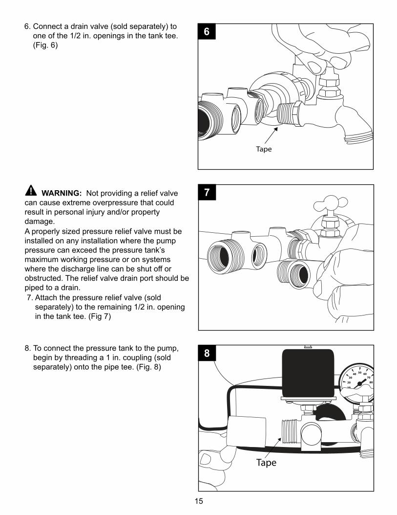
6. Connect a drain valve (sold separately) to one of the 1/2 in. openings in the tank tee. (Fig. 6)
IL1156
Tape
6
WARNING: Not providing a relief valve can cause extreme overpressure that could result in personal injury and/or property damage.A properly sized pressure relief valve must be installed on any installation where the pump pressure can exceed the pressure tank’s maximum working pressure or on systems where the discharge line can be shut off or obstructed. The relief valve drain port should be piped to a drain. 7. Attach the pressure relief valve (sold
separately) to the remaining 1/2 in. opening in the tank tee. (Fig 7)
8. To connect the pressure tank to the pump, begin by threading a 1 in. coupling (sold separately) onto the pipe tee. (Fig. 8)
IL1157
10
20
3040 50 60
70
80
IL1158
Tape
7
8
16
WARNING: This equipment is intended for installation by a technically qualified electrician. Failure to install it in compliance with national and local electrical codes may result in electrical shock or fire hazard, unsatisfactory performance, and equipment failure.
WARNING: Always disconnect power source before working on or near the pump, its connected load and wiring. If the power disconnect is out of sight, lock it in the open position and tag to prevent unexpected application of power.NOTE: Pump is a 3-wire pump and requires a control box (See chart on page 5). All models require 230-volt service.
ELECTRICAL HOOKUP FROM THE HOUSE TO PUMP AND PRESSURE TANK
9. Add additional couplings, unions and pipe (all sold separately) as necessary to reach the pump. (Fig. 9)
NOTE: Schedule 80 pipe recommended10
20
3040 50 60
70
80
Schedule 80 Pipe Shown
9
1. Remove the cover from the control box (sold separately) and mount it in an indoor location protected from moisture. (Fig. 1)
L1 L2 R Y B
TerminalL2
TerminalR
TerminalY
TerminalB
GreenGroundScrew
TerminalL1
GreenGroundScrew
1
17
2. Thread the electrical wire from pump into the right opening in the bottom of the control box and tighten the electric wire strain relief securely. (Fig. 2)
L1 L2 R Y B
IL1174
2
L1 L2 R Y B
IL1176
3. Attach the black, yellow and red wires to the appropriate terminals marked “B”, “Y” and “R”. (Fig. 3)
L1 L2 R Y B
IL1175
3
4. Connect the green ground wire from the pump to the green ground screw in the lower right corner of the control box. (Fig. 4)
4
18
L1 L2 R Y B
IL1178
L1 L2 R Y B
IL1179
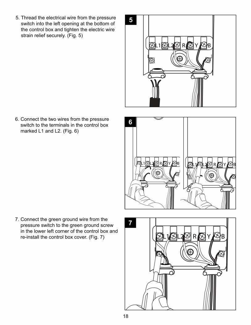
6. Connect the two wires from the pressure switch to the terminals in the control box marked L1 and L2. (Fig. 6)
6
L1 L2 R Y B
IL1180
77. Connect the green ground wire from the pressure switch to the green ground screw in the lower left corner of the control box and re-install the control box cover. (Fig. 7)
L1 L2 R Y B
IL1177
5. Thread the electrical wire from the pressure switch into the left opening at the bottom of the control box and tighten the electric wire strain relief securely. (Fig. 5)
5
19
8. Remove cover from pressure switch and screw the switch into the 1/4 in. opening on the top of the pipe tee. (Fig. 8)
8
IL1162
L4L1
Strain Relief
L4L1 L4L1
9. Thread the cable from the house electrical service through one of the holes in the side of the pressure switch and tighten down the electric wire strain relief.
CAUTION: Do not crush wire. (Fig. 9)
10. Connect the two wires from the house electrical service to the outside pressure switch terminals (L1 and L4). (Fig. 10)
9
10
20
IL1165
L3L2
IL1167
L2L3
11. Thread the cable from the control box through the remaining hole in the side of the pressure switch and tighten down the electric wire strain relief.
CAUTION: Do not crush wire. (Fig. 11)
11
1212. Connect the two wires from the control box to the inside pressure switch terminals (L2 and L3). (Fig. 12)
13. Connect green ground wires from the control box cable and the house electric cable to the two ground screws on base of pressure switch. Replace switch cover. (Fig 13)
IL1182
Ground Screws
FromControl Box
FromPower Source
13
21
TROUBLESHOOTING
PROBLEM POSSIBLE CAUSE CORRECTIVE ACTIONFuses blow 1. Incorrect voltage at motor 1. Check for correct wire size.
Replace undersize wire. Check line voltage, contact power company if voltage is incorrect
2. Defective fuse box or incorrect fuses 2. Inspect fuse box wiring and correct. Install the proper fuses
4. Control box malfunction 4. See control box checking and repairing procedures. Replace defective components
5. Defective drop cable insulation 5. Check drop cable insulation resistance. Pump must be pulled to replace defective cable
6. Motor malfunction 6. Check motor winding resistance. Pump must be pulled to replace defective motor
7. Pump malfunction 7. If all above checks are good, then pump is probably bound. Pump must be pulled. Check for sand or pump shaft misalignment. Correct well condition if sand is the problem
Motor won’t start. Fuses don’t blow
1. No power to start motor 1. Check voltage at line side of fuse box. Contact power company if no power is reaching box. Check voltage at load side of fuse box and at other control devices in circuit. Make necessary corrections
2. Defective drop cable or motor 2. Check motor winding resistance. Pump must be pulled to replace defective cable or motor
22
TROUBLESHOOTING
PROBLEM POSSIBLE CAUSE CORRECTIVE ACTIONMotor runs, but delivers little or no water
1. Air locked pump 1. Normal delivery may resume if water pump is started and stopped at one minute intervals
2. Gas or air in well water 2. Connect hose to service valve. Run water thru hose submerged in water in clear jar. Observe for air bubbles from hose outlet. If tank is standard type, the air volume control may be defective - replace; otherwise, have well checked for proper water level as pump may be drawing air. Lower pump and/or correct well condition
3. Low water level in well or pumping too much from well
3. Throttle pump with gate valve. Lower pump setting if depth of well is adequate
4. Defective or improperly installed check valve
4. Pump must be raised to replace or reinstall correctly
5. Leak in drop pipe damaged section 5. Raise pump, check pipe for leak and replace
6. Pump inlet screen blocked 6. Raise pump and clean screen. Verify that well is clean. Reset pump at less depth if possible
7. Worn pump 7. Pull pump and replace damaged components
8. Broken pump shaft or motor shaft or worn coupling
8. Pull pump, inspect shafts and coupling for damage. Replace defective components
Pump operates properly, but won’t shut off
1. Pressure switch 1. Readjust switch to lower shut off pressure setting, clean contacts or replace switch
2. Low water level 2. Throttle pump outlet at gate valve or readjust pressure switch to lower shutoff pressure setting
3. Leak in drop pipe or worn pump 3. Throttle pump output at gate valve or readjust pressure switch to lower shut off pressure setting. If pump does not shut off, pump must be raised and defect repaired
23
TROUBLESHOOTING
PROBLEM POSSIBLE CAUSE CORRECTIVE ACTIONPump starts too often 1. Pressure switch 1. Readjust switch to wider
2. Air volume in tank incorrect 2. Check pressure in tank. Set at 2 lbs. below turn on pressure of the pressure switch. i.e. 30/50 pressure switch should have tank pressure of 28 lbs.
3. Check valve defect or leak in drop pipe
3. Throttle pump output at gate valve. If pump does not shut off, pump must be raised and defect repaired
This product is warranted for one year afrom the date of purchase or two years from the date of manufacture, whichever occurs first. Subject to the conditions hereinafter set forth, the manufacturer will repair or replace to the original consumer any portion of the product which proves defective due to defective materials or workmanship. To obtain warranty service, contact the dealer from whom the product was purchased. The manufacturer retains the sole right and option to determine whether to repair or replace defective equipment, parts, or components. Damage due to conditions beyond the control of the manufacturer is not covered by this warranty.THIS WARRANTY WILL NOT APPLY: (a) To defects or malfunctions resulting from failure to properly install, operate, or maintain the unit in accordance with printed instructions provided; (b) to failures resulting from abuse, accident, or negligence, or use of inappropriate chemicals or additives in the water; (c) to normal maintenance services and the parts used in connection with such service; (d) to units which are not installed in accordance with normal applicable local codes, ordinances, and good trade practices; and (e) if the unit is used for purposes other than for what it was designed and manufactured.RETURN OF WARRANTED COMPONENTS: Any item to be repaired or replaced under this warranty must be returned to the manufacturer at Kendallville, Indiana or such other place as the manufacturer may designate, freight prepaid.THE WARRANTY PROVIDED HEREIN IS IN LIEU OF ALL OTHER EXPRESS WARRANTIES, AND MAY NOT BE EXTENDED OR MODIFIED BY ANYONE. ANY IMPLIED WARRANTIES SHALL BE LIMITED TO THE PERIOD OF THE LIMITED WARRANTY AND THEREAFTER ALL SUCH IMPLIED WARRANTIES ARE DISCLAIMED AND EXCLUDED. THE MANUFACTURER SHALL NOT, UNDER ANY CIRCUMSTANCES, BE LIABLE FOR INCIDENTAL, CONSEQUENTIAL OR SPECIAL DAMAGES, SUCH AS, BUT NOT LIMITED TO DAMAGE TO, OR LOSS OF, OTHER PROPERTY OR EQUIPMENT, LOSS OF PROFITS, INCONVENIENCE, OR OTHER INCIDENTAL OR CONSEQUENTIAL DAMAGES OF ANY TYPE OR NATURE. THE LIABILITY OF THE MANUFACTURER SHALL NOT EXCEED THE PRICE OF THE PRODUCT UPON WHICH SUCH LIABILITY IS BASED.This warranty gives you specific legal rights, and you may have other rights which vary from state to state. Some states do not allow limitations on duration of implied warranties or exclusion of incidental or consequential damages, so the above limitations may not apply to you.
WARRANTY
In those instances where damages are incurred as a result of an alleged pump failure, the Homeowner must retain possession of the pump for investigation purposes.