Garmin Corporation, No. 68, Zhangshu 2nd Road, Xizhi Dist., New Taipei City 221, Taiwan (R.O.C.) Tel. 886/2.2642.9199 Fax 886/2.2642.9099
Except as expressly provided herein, no part of this addendum may be reproduced, copied, transmitted, disseminated, downloaded, or stored in any storage medium, for any purpose without the express prior written consent of Garmin. Garmin hereby grants permis-sion to download a single copy of this manual and of any revision to this manual onto a hard drive or other electronic storage medium to be viewed and to print one copy of this manual or of any revision hereto, provided that such electronic or printed copy of this manual or revision must contain the complete text of this copyright notice and provided further that any unauthorized commercial distribution of this manual or any revision hereto is strictly prohibited. Information in this document is subject to change without notice. Garmin reserves the right to change or improve its products and to make changes in the content without obligation to notify any person or orga-nization of such changes or improvements.
Garmin® is a registered trademark, and GTX™ and GDL™ are trademarks of Garmin Ltd. or its subsidiaries and may not be used without the express permission of Garmin Ltd. or its subsidiaries. Sirius and XM are trademarks of SiriusXM Radio Inc.
September 2012 190-00356-30 Revision J
190-00356-30 Rev J
The screen display examples shown in this addendum are taken from the GNS 430W and GNS 530W. TIS and Weather Data Link Display Interface functionality is the same for the 400W and 500W Series Units. TIS Traffic Display and Weather Data Link are available only when the 400W/500W units are configured with the GTX 330 Mode S Transponder and GDL 69/69A Data Link
Transceiver, respectively.
i
Introduction
Warnings and Cautions
WARNING: Terrain data are obtained from third party sources. Garmin is not able to independently verify the accuracy of this data which should be used only as an aid for situational awareness. Terrain data must not be used as the sole basis for deci-sions or maneuvers to avoid terrain or obstacles. Terrain data must not be used for navigation.
WARNING: Do not use data link weather information for maneuvering in, near, or around areas of hazardous weather. Infor-mation contained within data link weather products may not accurately depict current weather conditions.
WARNING: Do not use the indicated data link weather product age to determine the age of the weather information shown by the data link weather product. Due to time delays inherent in gathering and processing weather data for data link transmission, the weather information shown by the data link weather product may be significantly older than the indicated weather product age.
CAUTION: Use the 400W/500W Series Units at your own risk. To reduce the risk of unsafe operation, carefully review and understand all aspects of the Owner’s Manual and the Flight Manual Supplement, and thoroughly practice basic operation prior to actual use.
CAUTION: The Global Positioning System is operated by the United States government, which is solely responsible for its accuracy and maintenance. The system is subject to changes which could affect the accuracy and performance of all GPS equipment. Although Garmin 400W/500W Series Units are precision electronic NAVigation AIDS (NAVAID), any NAVAID can be misused or misinterpreted and therefore become unsafe.
CAUTION: The Jeppesen database incorporated in the Garmin 400W/500W Series Units must be updated regularly in order to ensure that its information is current. Updates are released every 28 days. A database information packet is included in your Garmin 400W/500W Series Unit package. Pilots using an out-of-date database do so entirely at their own risk.
CAUTION: The Weather Data Link, TIS, TAWS, HTAWS, and TERRAIN information contained in this Pilot’s Guide Addendum is not intended to replace the documentation that is supplied with the applicable Garmin 400W/500W Series Unit and the GTX 330 Transponder. The user must know how to operate the 400W/500W Series Unit and be knowledgeable of the information in the 400W/500W Pilot’s Guide.
TIS CAUTION: TIS is NOT intended to be used as a collision avoidance system and does not relieve pilot responsibility to “see and avoid” other aircraft. TIS should not be used for avoidance maneuvers during IMC or other times when there is no visual contact with the intruder aircraft. TIS is intended only to assist in visual acquisition of other aircraft in VMC. Avoidance maneu-vers are not recommended, nor authorized, as a direct result of a TIS intruder display or TIS alert. While TIS is a useful aid to visual traffic avoidance, it has some system limitations that must be fully understood to ensure proper use. Many of these limitations are inherent in secondary radar surveillance. In other words, the information provided by TIS will be no better than that provided to ATC.
NOTE: Do not rely solely upon data link services to provide Temporary Flight Restriction (TFR) information. Always confirm TFR information through official sources such as Flight Service Stations or Air Traffic Control.
NOTE: For software version 4.00 and later: when configured for helicopters (the helicopter icon will be displayed), black, circu-lar or oblong “cutouts” will be displayed on the Terrain Page around airports and heliports, to enhance viewing of the informa-tion displayed for those locations. The Terrain legend (shown in the lower right of the display on the Terrain Page) defines the color black as -500 ft. However, this does not apply to the black cutouts surrounding the airports and heliports. The cutouts are for display purposes only and do not affect the performance of HTAWS.
190-00356-30 Rev J
ii
Introduction
Table of Contents
Table of ContentsPart One: Traffic Information Service (TIS) Interface ...................1
Section 1: TIS Operation and Symbology ....................1TIS Operation ............................................................................1How TIS differs from TCAS .........................................................2TIS Limitations ..........................................................................2Improving TIS ............................................................................3TIS Symbology ..........................................................................3
Section 2: Control and Display .....................................5TIS Traffic Display Status and Pilot Response ..............................5Traffic Ground Track .................................................................6Traffic Warning Window ............................................................6Traffic Page ...............................................................................6Traffic Page Display Range ........................................................6Map Page .................................................................................7
Configuring TIS Traffic Data on the Map Page .......................7Highlighting TIS Traffic Using Map Page Panning ........................8
Part Two: XM Radio Interface ......................................................11
Section 1: Introduction ...............................................11Overview ................................................................................11SiriusXM Satellite Radio Pages ................................................11
XM NAV Pages ..................................................................11XM WPT Pages ..................................................................12XM AUX Pages ..................................................................12
Section 2: SiriusXM Weather .......................................12Weather Product Age ..............................................................13SiriusXM Weather ...................................................................14
NEXRAD U.S. and Canadian Coverage ...............................15NEXRAD Intensity ..............................................................15NEXRAD Abnormalities ......................................................15NEXRAD Limitations ..........................................................16
TFR Information ......................................................................19Lightning (LTNG) .....................................................................21
Cell Movement (CELL MOVE) ..................................................21Winds Aloft .............................................................................22
Winds Aloft Altitude ..........................................................23Section 3: XM AUX Pages ............................................23
XM Information Page .............................................................23XM WX Timestamps ................................................................24
XM Audio Menu .....................................................................27Add to Presets List ..................................................................27Enter Channel Number ............................................................28Display Channel In List ............................................................28Display Artist In List ................................................................29Display Title In List ..................................................................29Enable/Mute Audio Output ......................................................30Change Volume ......................................................................30
Part Three: TAWS Interface .............................................................31
External TAWS Inhibit Control ............................................34TAWS Manual Test ..................................................................34TAWS Symbols ........................................................................34General Database Information .................................................36Database Versions ...................................................................36Database Updates ..................................................................37Terrain/Obstacle Database Areas of Coverage ..........................37
Page Menu ........................................................................47Inhibit Mode ...........................................................................48
External HTAWS Inhibit Control ..........................................48Reduced Protection Mode .......................................................48Mute Active Caution ...............................................................49HTAWS Manual Test ................................................................50HTAWS Legend .......................................................................50HTAWS Symbols ......................................................................51Airport/Heliport Terrain “Cutouts” ...........................................52General Database Information .................................................52Database Versions ...................................................................52Database Updates ..................................................................53Terrain Database Areas of Coverage ........................................54Obstacle Database Areas of Coverage .....................................54
Section 3: HTAWS Alerts .............................................54Forward Looking Terrain Avoidance .........................................55Voice Call Out Aural Alert ........................................................55HTAWS Not Available Alert ......................................................56HTAWS Failure Alert ................................................................56HTAWS Alert Summary ............................................................56Pilot Actions ...........................................................................57
Voice Call Out Selection .....................................................58
Part Five: Terrain Proximity Interface .........................................59
Introduction ............................................................................59Displaying Terrain Proximity .....................................................59Terrain Proximity 120° Arc or 360° Rings .................................60Terrain Proximity Aviation Data ................................................60Terrain Proximity Legend .........................................................61Terrain Proximity Limitations....................................................62System Status .........................................................................62
Part Six: Garmin GTS 8XX Series Interface ................................63
Introduction ............................................................................63GTS 8XX Series Description .....................................................63Power-up Self-Test ..................................................................63
User-initiated Test ...................................................................64Voice Announcements .............................................................64Switching Between Standby and Operating Modes ..................64Altitude Display Mode .............................................................65Traffic Page .............................................................................65Traffic Warning Window ..........................................................66Traffic Page Display Range ......................................................66Configuring Traffic Data on the Map Page ................................67Highlighting Traffic Data Using Map Panning ...........................68Monitoring Traffic ....................................................................68Failure Response .....................................................................68Description of Traffic Advisory Criteria ......................................68
Part Seven: Garmin GDL 88 Interface .............................................69
NOTE: Part One of this Addendum assumes the user has experience operating the 400W/500W Series units and the Garmin GTX 330 Transponder.
The Traffic Information Service (TIS) provides a graphic display of traffic advisory information in the cockpit for non-TCAS (Traffic alert and Collision Avoidance System) equipped aircraft. TIS is a ground-based service providing relative location of all ATCRBS (Air Traffic Control Radar Beacon System) Mode A and Mode C transponder-equipped aircraft within a specified service volume. The TIS ground sensor uses real-time track reports to generate traffic notification. TIS Traffic display is available to aircraft equipped with a Mode S Data Link such as the Garmin GTX 330 Transponder. TIS Traffic from a GTX 330 Transponder can then be displayed on a Garmin 400W/500W Series unit. Surveillance data includes all transponder-equipped aircraft within the coverage volume. Aircraft without an operating transponder are invisible to TIS. TIS displays up to eight traffic targets within seven nautical miles horizontally from 3000 feet below to 3500 feet above the requesting aircraft.
The TIS is a ground-based service that displays nearby aircraft on your 400W/500W-series display. For the TIS feature to inform you of a nearby aircraft’s presence, several conditions must be met:
• YouraircraftmustbeequippedwithaModeSdata link transponder, such as the GTX 330.
• YoumustbewithinrangeofaModeSradarthatprovides the TIS service. Not all Mode S ground radars provide TIS service.
• The“intruder”aircraftmustbeequippedwithatransponder, and that transponder must be turned on. Aircraft that are not equipped with operating transponders will not be visible to the Mode S surveillance radar.
• The “intruder”aircraftmustbewithintheTIScoverage volume for your aircraft. TIS displays up to eight traffic targets within seven nautical miles horizontally from the requesting aircraft, and from 3,000 feet below to 3,500 feet above the requesting aircraft.
• Bothyouraircraftandtheintruderaircraftmustbe visible to the Mode S surveillance radar on the ground.
Always remember that TIS cannot alert you to the presence of aircraft that are not equipped with transponders, nor can it alert you to aircraft that may be nearby, but obscured from the ground surveillance radar by intervening terrain.
TIS Coverage Volume (not to scale)
7.0 nm3,500 ft
3,000 ft
TIS Operation and Symbology
190-00356-30 Rev J
2
TIS Operation and Symbology
Part One: Section 1
How TIS differs from TCAS
The main difference between TIS and TCAS is the source of surveillance data. TCAS uses an airborne interrogator with a one-second update rate, while TIS uses the terminal Mode S ground interrogator and its Data Link to provide about a five-second update rate. The range accuracy of TIS and TCAS is similar.
TIS Limitations
NOTE: This section on TIS Limitations is not com-prehensive. Garmin recommends the user review the TIS Limitations section of the Aeronautical Information Manual, Section 1-3-5.
TIS is NOT intended to be used as a collision avoidance system and does not relieve the pilot of responsibility to “seeandavoid”otheraircraft.TISshouldnotbeusedforavoidance maneuvers during IMC or other times when there is no visual contact with the intruder aircraft. TIS is intended only to assist in visual acquisition of other aircraft in VMC. No recommended avoidance maneuvers are provided for, nor authorized, as a direct result of a TIS intruder display or TIS advisory.
While TIS is a useful aid to visual traffic avoidance, it has some system limitations that must be fully understood to ensure proper use. Many of these limitations are inherent in secondary radar surveillance. In other words, the information provided by TIS will be no better than that provided to ATC. TIS will only display aircraft with operating transponders installed.
TIS relies on surveillance of the Mode S radar, which isa“secondarysurveillance”radarsimilartotheATCRBS.TIS operation may be intermittent during turns or other maneuvering. TIS is dependent on two-way, “line-of-sight”communicationbetweentheaircraftandtheModeS radar. Whenever the structure of the client aircraft comes between the transponder antenna (usually located
on the underside of the aircraft) and the ground-based radar antenna, the signal may be temporarily interrupted. Other limitations and anomalies associated with TIS are described in the AIM, Section 1-3-5.
Garmin is not responsible for Mode S geo-graphical coverage. Operation of the ground
stations is the responsibility of the FAA. Refer to the Aeronautical Information Manual for a Terminal Mode S Radar Site Map covering the
U.S.
NOTE: TIS will be unavailable at low altitudes in many areas of the U.S., particularly in mountain-ous regions. Also, when flying near the “floor” of radar coverage in a particular area, intruders below the client aircraft may not be detected by TIS.
TIS information is collected one radar scan prior to the scan during which the uplink occurs. Therefore, the surveillance information is approximately five seconds old. Inordertopresenttheintrudersina“realtime”position,theTISgroundstationusesa“predictivealgorithm”initstracking software. This algorithm uses track history data to extrapolate intruders to their expected positions consistent with the time of display in the cockpit. Occasionally, aircraft maneuvering will cause this algorithm to induce errors in the 400W/500W display. These errors primarily affect relative bearing information and traffic target track vector (it will lag); intruder distance and altitude will remain relatively accurate and may be used to assist in “seeandavoid.”Someofthemorecommonexamplesofthese errors follow:
190-00356-30 Rev J
3
TIS Operation and Symbology
Part One: Section 1
•Whenclientor intruder aircraft maneuvers exces-sively or abruptly, the tracking algorithm may report incorrect horizontal position until the maneuvering aircraft stabilizes.
•When a rapidly closing intruder is on a course that crosses the client aircraft course at a shallow angle (either overtaking or head on) and either aircraft abruptly changes course within ¼ NM, TIS may display the intruder on the opposite side of the client than it actually is.
These are relatively rare occurrences and will be corrected in a few radar scans once the course has stabilized.
Improving TIS
Users of TIS can render valuable assistance in the correction of malfunctions by reporting their observations of undesirable performance. Reporters should identify the time of observation, location, type and identity of aircraft, and describe the condition observed; the type of transponder processor and software in use can also be useful information. Since TIS performance is monitored by maintenance personnel other than ATC, it is suggested that malfunctions be reported in the following ways:
• ByFAAForm8000-7,SafetyImprovementReport,a postage-paid card designed for this purpose. These cards may be obtained at FAA FSSs, General Aviation District Offices, Flight Standards District Offices, and General Aviation Fixed Based Opera-tions.
TIS Symbology
TIS traffic is displayed on the 400W/500W Series unit according to TCAS symbology, graphically displayed on a dedicated graphical page (Traffic Page; see below), and on the moving Map Page. A Traffic Advisory (TA) symbol appears as a solid yellow circle (or half circle on the outer range ring if the traffic is outside the range of the dedicated Traffic Page). Proximity Advisories (PA) are displayed as a solid diamond, and other traffic is displayed as an open diamond. PA and other traffic is normally displayed in white, or it may be alternatively configured for display in cyan. When configured for cyan, the traffic page range rings and markings are displayed in white. Altitude deviation from own aircraft altitude is displayed above the target symbol if traffic is above own aircraft altitude, and below the symbol if they are below own aircraft altitude. Altitude trend is displayed as an up arrow (> +500 ft/min), down arrow (< -500 ft/min), or no symbol if less than 500 ft/min rate in either direction.
•TrafficAdvisories(TA)—Yellow
• P ro x im i t y Ad v i s o r i e s ( PA )—Wh i t e (may be configured as Cyan)
•Other—White(maybeconfiguredasCyan)
190-00356-30 Rev J
4
TIS Operation and Symbology
Part One: Section 1
Own Aircraft
“Other” Traffic—This symbol represents traffic detected within the selected display
range that does not generate a TA.
Traffic Advisory (TA)—This symbol is generated when traffic meets the advisory criteria described in TIS Operational Proce-
dures.
Traffic Ground Track is indicated on the 400W/500W display by a “target track vector”, a short line
displayed in 45-degree increments. This vector shows the flight direc-
tion of the traffic.
The TIS audio alert is generated from the GTX 330 whenever the number of Traffic Ad-visories on the 400W/500W display increases
from one scan to the next. Limiting Traffic Advisories only reduces the “nuisance” alerting due to proximate aircraft. For example, when the first Traffic Advisories appears on the TIS display, the user is alerted audibly. So long as
a single aircraft remains on the TIS display, no further audio alert is generated. If a second (or
more) aircraft appears on the display, a new audio alert is sounded.
If the number of Traffic Advisories on the TIS display decreases and then increases, a new
audio alert is sounded. The TIS audio alert is also generated whenever TIS service becomes unavailable. The volume, pitch, and duration
of the audio alert (including the choice between a male or female voice) is configured during
installation.
The following TIS audio alerts are available:
• “Traffic” —TIS traffic alert is received.• “Traffic Not Available” — TIS service is not
available or out of range.
190-00356-30 Rev J
5
Part One: Section 2
TIS Controls and Display
Section 2: Control and Display
TIS Traffic Display Status and Pilot Response
•STBY—Whenthe400W/500WdisplaysSTBYin the upper right hand corner of the display the TIS system is in standby mode and cannot display traffic data.
•OPER—Whenthe400W/500WdisplaysOPERin the upper right hand corner of the display the TIS system is in operational mode and available to display traffic on the Traffic or Map Page.
•AGE— If traffic data are not refreshed within 6seconds,anageindicator(e.g.,“AGE00:06”)is displayed in the lower right corner of the dis-play (when displaying traffic). The pilot should be aware that the quality of displayed traffic is reduced in this condition.
•TRFCCST—If data are still not received between six and twelve seconds, the“TRFCCST”(trafficcoasting) banner located above the AGE timer will indicate that displayed traffic is held even though the data are not current. The pilot should be aware that the quality of displayed traffic is reduced in this condition.
Traffic Age Indication showing “traffic coasting”.
•TRFCRMVD—If data are still not received after twelve seconds, the“TRFCRMVD”bannerwillindicate that traffic has been removed from the display due to the age of the data being too old
to“coast”(forthetimeperiodafter12secondsfrom the last receipt of a TIS message). The pilot should be aware that traffic may be present but not shown.
Traffic Page displaying “TRFC RMVD” banner.
•UNAVAIL—After a 60 second period elapses with no data, TIS is considered to be unavailable. This stateisindicatedbythetext“UNAVAIL”.Thepilotshouldbeawarethat“UNAVAIL”couldindicatea TIS coverage limitation due to a line-of-sight situation, a low altitude condition, no TIS service, or a result of flying directly over the radar site providing coverage (cone of silence).
•NODATA—“NODATA”isdisplayedwhennodata are being received from the GTX 330. The pilot should be aware that this status may be a normal mode of operation in a dual transponder installation where the GTX 330 with TIS is not the selected transponder. The GTX 330 may not be powered on.
•DATAFAIL— “DATAFAIL” is displayedwhendata are being received from GTX 330, but there was a failure detected in the data stream. The pilot should see the dealer for corrective action.
•FAILED—“FAILED”isdisplayedwhentheGTX330 has indicated it has failed. The pilot should see the dealer for corrective action.
190-00356-30 Rev J
6
Part One: Section 2
TIS Controls and Display
Traffic Ground Track
Traffic ground track is indicated in the 400W/500W displaybya “target trackvector”, a short linedisplayedin 45° increments, extending in the direction of target movement.
Traffic Target Track Vector.
Traffic Warning Window
When the unit is on any page (other than the NAV Traffic Page or when a TAWS/Terrain, or Dead Reckoning pop-up is displayed) and a traffic threat is imminent, the Traffic Warning Window is displayed. The Traffic Warning Window shows a small thumbnail map which can take the user to the Traffic Page by pressing ENT, or go back to the previous page by pressing CLR.
Traffic Warning Window
NOTE: The Traffic Warning Window is disabled when the aircraft ground speed is less than 30 knots or when an approach is active.
Traffic Page
TIS Traffic data are displayed on two 400W/500W Series unit pages, the Traffic Page and the Map Page. The 500W Series unit can also be configured to display a traffic thumbnail window below the VLOC frequency window. Unlike other forms of traffic, TIS traffic does not require heading data to be valid on the map. The only difference between TIS and other traffic data occurs on the Traffic Page. If heading is available, then the traffic data are compensated and displayed as heading-up. If it’s not available, the Traffic Page is a track-up display. It is labeled on the upper portion of the Traffic Page.
Traffic Page Display RangeVarious display ranges can be selected for optimal
display of TIS traffic information.
To change the display range on the Traffic Page:
Press RNG to zoom through the range selections which are: 12/6 NM, 6/2 NM, and 2 NM.
190-00356-30 Rev J
7
TIS Controls and Display
Part One: Section 2
Map PageTIS traffic is displayed on the Map Page in addition to
the Traffic Page.
The Map Page displaying traffic.
Configuring TIS Traffic Data on the Map Page
To configure TIS traffic on the Map Page:
1. Turn the small right knob to select the Map Page.
2. Press the MENU key. Turn the small right knob to select “Setup Map?”
3. The flashing cursor highlights the GROUP field. Turn the small right knob to select “Traffic” and press ENT.
4. Turn the large right knob to select the desired Traffic Mode option. Turn the small right knob to select the desired option and press ENT. Repeat the step for Traffic Symbol and Traffic Label.
5. Press CLR to return the Map Page.
The traffic mode selection menu allows the user to choose from the following: •All trfc - All traffic is displayed on theMap
Page. •TA/PA -Only traffic advisories and proximity
advisories are displayed on the Map Page. •TAonly-Onlytrafficadvisoriesaredisplayedon
the Map Page.
From the Map Page you can display traffic in a thumbnail format in any of the top three (400W Series) or four (500W Series) data fields on the right side of the Map Page.
Thumbnail Traffic displayed on the GNS 430W.
NOTE: The thumbnail will display traffic coasting “TRFC CST” or traffic removed
“TRFC RMVD” in the lower right when TIS messages have been missed.
To display Thumbnail Traffic on the Map Page:
1. Turn the small right knob to select the Map Page.
2. Press the MENU key and display the Page Menu.
3. Turn the small right knob to select “Change Fields?” and press ENT.
4. Select one of the top three (400W Series) or four (500W Series) configurable fields. Select “TRFC” from the Select Field Type List and press ENT. Note that the thumbnail range defaults to 6 NM and cannot be changed.
190-00356-30 Rev J
8
TIS Controls and Display
Part One: Section 2
Highlighting TIS Traffic Using Map Page Panning
Another Map Page feature is panning, which allows you to move the map beyond its current limits without adjusting the map scale. When you select the panning function — by pressing the small right knob — atarget pointer will flash on the map display. A window also appears at the top of the map display showing the latitude/longitude position of the pointer, plus the bearing and distance to the pointer from your present position.
Displaying traffic range and altitude separa-tion using the Map Panning feature.
To activate the panning feature and pan the map display:
1. Press the small right knob to activate the panning target pointer.
2. Turn the small right knob to move up (turn clockwise) or down (counterclockwise).
3. Turn the large right knob to move right (turn clockwise) or left (counterclockwise).
4. To cancel the panning function and return to your present position, press the small right knob.
When the target pointer is placed on traffic, the traffic range and altitude separation are displayed.
190-00356-30 Rev J
9
TIS Operational Procedures
Part One: Section 3
Section 3: TIS Operational Procedures
Introduction
TIS warns the user with voice and visual traffic advisories whenever it predicts an intruder to be a threat (see illustration). Voice and visual data are sent from the GTX 330. The user should not start evasive maneuvers using information from the 400W/500W display or on a traffic advisory only. The display and advisories are intended only for assistance in visually locating the traffic, due to the lack in resolution and coordination ability. The flight crew should attempt to visually acquire the intruder aircraft and maintain a safe separation in accordance with the regulatory requirements and good operating practice. If the flight crew cannot visually acquire the aircraft, they should contact ATC to obtain any information that may assist concerning the intruder aircraft. Based on the above procedures, minor adjustment to the vertical flight path consistent with air traffic requirements are not considered evasive maneuvers.
Power-Up Test
The TIS interface performs an automatic test during power-up.
•If the system passes the power-up test, the Standby Screen appears on the Traffic Page.
•If the systempasses thepower-up test and theaircraft is airborne (as determined by system configuration at the time of installation, see your installer for detailed criteria information), traffic is displayable on the Traffic Page in operating mode.
•If the system fails the power-up test, the “NODATA”, “DATAFAIL”, or “FAILED”message isdisplayed. See your installer for corrective action if the “DATA FAIL”, or “FAILED”message isdisplayed.The“FAILED”message indicates the
GTX330hasfailed.The“DATAFAIL”messageindicates data are being received from the GTX 330 but a failure was detected in the data stream. The“NODATA”messageindicatesthatdataarenot being received from the GTX 330.
NOTE: “NO DATA” may be a normal mode of operation in a dual transponder installation where the GTX 330 with TIS is not the selected transponder.
•UNAVAIL—When a 60 second period elapses with no data, TIS is considered to be unavailable. Thisstateisindicatedbythetext“UNAVAILABLE”(500WSeries) and “UNAVAIL” (400WSeries).Thepilotshouldbeawarethat“UNAVAIL”couldindicate a TIS coverage limitation due to a line-of-sight situation, a low altitude condition, no TIS service, or a result of flying directly over the radar site providing coverage (cone of silence).
Conditions for Traffic Advisories
The following condition causes TIS to display a Traffic Advisory (TA) on the 400W/500W Series unit:
• The intruder aircraft approaches your aircraft on a course that will intercept (defined by a 0.5 NM horizontal radius and a relative altitude of ± 500 feet) your course within 34 seconds.
0.5 nm
Intruder Aircraft
+ 500 ft
This area within 34 seconds - 500 ft
190-00356-30 Rev J
10
TIS Operational Procedures
Part One: Section 3
Manual Override
Theusercanmanuallyswitchbetweenstandby(STBY)and operating (OPER) mode of operation to manually override automatic operation.
To place the display into operating mode from the standby mode (to display TIS traffic):
1. Turn the cursor on and highlight “STBY”.
2. Turn the small right knob to select “OPER?”.
3. Press ENT to confirm.
To place the display into standby mode from operating mode (to stop displaying TIS traffic):
1. Turn the cursor on and highlight “OPER”.
2. Turn the small right knob to select “STBY?”
3. Press ENT to confirm.
“DATA FAIL” Message
The “NO DATA” message indicates that data are not being received from the GTX 330.
NOTE: This may be a normal mode of opera-tion in a dual transponder installation where
the GTX 330 with TIS is not the selected transponder.
Flight Procedures
Once the aircraft is airborne (determined by system configuration at the time of installation) the system switches from standby mode to operating mode. The 400W/500W Series unit displays OPER in the upper right hand corner of the display and begins to display traffic on the Traffic or Map Page.
The TIS Traffic Advisory (TA) should alert the crew to use additional vigilance to identify the intruding aircraft. Any time the traffic symbol becomes a yellow circle or a voice warning is announced, conduct a visual search for the intruder. If successful, maintain visual contact to ensure safe operation. See Section 2: Control and Display for a description of pilot responses to TIS display messages.
After Landing
Once the aircraft is “ground-borne” (determined bysystem configuration at the time of installation) the system switches from operating mode to standby mode. The 400W/500W Series unit displays “STBY”. As describedpreviously, both the standby and operating modes can be manually overridden by the display controls.
190-00356-30 Rev J
11
XM Radio Introduction
Part Two: Section 1
Part Two: XM Radio InterfaceSection 1: Introduction
Overview
The GDL 69 is a remote sensor that receives broadcast weather data from a data service of SiriusXM Satellite Radio Inc. The GDL 69A is similar to the GDL 69, but also receives audio entertainment broadcasts from another service of SiriusXM Satellite Radio. The 400W and 500W series units serve as the display and control head for your remotely mounted GDL 69/69A radio.
Before the GDL 69/69A can be used, the unit must be activated by SiriusXM Satellite Radio with a service subscription through SiriusXM Satellite Radio. Please note that the GDL 69 is a weather data link. The GDL 69A is a weather data link and audio receiver. The data link service and the audio entertainment services must be activated separately.
YourGDL69orGDL69Aisshippedwithoneortworadio hardware identifications, respectively. These IDs serve as identification codes for your SiriusXM Satellite Radio-equipped GDL 69/69A and are needed in the activation process. The ID(s) is (are) attached to the Activation Instructions and printed on a label on the back of the unit. The IDs can also be retrieved through your unit in the SiriusXM Satellite Radio Information page of the Aux function. Contact your dealer or customer service if you are unable to locate the radio hardware IDs.
Weather and/or audio data from your GDL 69/69A are provided by SiriusXM Satellite Radio, a company separate and independent from Garmin Corporation. Have your radio hardware IDs ready before contacting SiriusXM Satellite Radio. During the process, you can select services for subscription. Keep in mind that the GDL 69 has no audio capability, audio services will not be available with the unit.
Follow the GDL 69/69A XM Satellite Radio Activation Instructions (190-00355-04) enclosed with your GDL 69/69A unit to activate the XM products.
The latest subscription information is available at: http://www.garmin.com/xm/
SiriusXM Satellite Radio PagesTo reach the SiriusXM Satellite Radio pages: 1. From any page, press and hold CLR to select
the Default NAV Page. (You may skip this step if you are already viewing any of the main pages.)
2. Turn the large right knob to select the AUX page group. “AUX” appears in the lower right corner of the screen.
3. Turn the small right knob to select the SiriusXM Audio, SiriusXM Satellite Radio Information, or XM WX Timestamps pages.
XM Weather page is displayed in the NAV page group. The XM Audio function pages are displayed in the AUX page group.
XM NAV PagesWhen a GDL 69 or GDL 69A is installed, the following
XM-related pages appear in the NAV group of pages:
•MapPage.TheMappage(thesecondpageintheNAV page group) becomes capable of displaying weather data and the boundaries of areas with Temporary Flight Restrictions (TFRs).
• XMWeatherPage.TheXMWeatherpageisinsertedin the NAV page group, immediately before the Terrain page. This page is like the map page, but can show NEXRAD weather data, colored flags showing which airports have METARs (current weatherobservations—MeteorologicalAerodromeReports), Lightning (LTNG) reports, Cell Move-ment, or Winds Aloft.
190-00356-30 Rev J
12
Part Two: Section 2
XM Weather
XM WPT Pages
When a GDL 69 or GDL 69A is installed, two SiriusXM Weather-relatedpagesareaddedto“airport”pagesintheWPT page group:
•Textual METAR Page. The Textual METAR page shows the text of the most recent METAR (Meteorological Aerodrome Report) that has been received for an airport.
•TAF Page. The TAF page shows the text of the most recent TAF (Terminal Aerodrome Forecast) that has been received for an airport.
XM AUX Pages
When a GDL 69 or GDL 69A is installed, the following XM pages appear in the AUX group of pages:
•XM Audio Page (GDL 69A only). See Section 4 below for a description of this page.
•XM Information Page. This page contains infor-mation that you will use when activating your XM satellite radio subscription. It also reports the GDL 69/69A’s software version number. SiriusXM Satel-lite Radio and SiriusXM Weather subscriptions are sold separately.
•XM Weather Timestamp Pages. This page show timestamp data for the most recently received XM weather data.
Section 2: SiriusXM WeatherThe SiriusXM Weather Function is capable of displaying
graphical weather information through the SiriusXM Satellite Radio Service when activated in the optional installation of the GDL 69/69A. Next Generation Weather Radar (NEXRAD), METARs symbols (METAR), Lightning (LTNG), Cell Movement (CELL MOVE), and Winds Aloft (WINDS) are displayed on the NAV pages. The types of products available depend on the subscription service with XM Satellite Radio.
Once you have activated an aviation weather service from SiriusXM Weather, the 400W/500W series unit can display the following aviation-related data:
•NEXRAD. An indication of the intensity of weather radar echoes from the National Weather Service’s network of NEXRAD (NEXt generation RADar) sites can be shown on the SiriusXM Weather Page and can optionally be overlaid on the Map page. (Both these pages are in the NAV page group.) Canadian Radar may also be avail-able.
•Radar Coverage. Whenever NEXRAD is shown, a cross-hatch pattern indicates the limits of NEXRAD radar coverage. The cross-hatched area shows where NEXRAD information is unavailable.
•Lightning (LTNG). When enabled, lightning strikesandcellsareshownasyellow“+”signs.Lightning information indicates the location of cloud-to-ground lightning strikes.
•Cell Movement (CELL MOVE). When enabled, Cell Movement shows the storm cells identified by the ground-based system. The movement is depicted by an arrow. The tip of the arrow represents where the cell is expected to be in 10 minutes from the time the cell location was determined.
190-00356-30 Rev J
13
Part Two: Section 2
XM Weather
•Winds Aloft (WINDS). The Winds Aloft selection provides the pilot with wind speed and direction. The winds at a given altitude are selected in the Winds Aloft Alt below the WINDS selection. The selected altitude is shown along with the product time.
•Textual Meteorological Aerodrome Reports (METARs). When you zoom in to show the air-port symbol associated with the colored flag for a graphical METAR, and move the Map Pointer to highlight that airport, you can then press ENT to see the Textual METAR page for that airport. The Textual METAR page is one of the airport pages of the WPT page group.
•Graphical Meteorological Aerodrome Reports (METARs). The XM Weather page (in the NAV page group) can show colored flags to indicate the level of current weather conditions at those airports for which textual METAR reports are available. The flags are color-coded to indicate the severity of the current weather at the airport: cyan for VFR conditions, green for Marginal VFR conditions, yellow for IFR conditions, or magenta of Low IFR conditions.
•Terminal Aerodrome Forecast (TAFs). A TAF page is added among the airport pages of the WPT page group. The TAF page differs from the Textual METAR page in that it describes forecast future weather conditions rather than current conditions.
•Temporary Flight Restrictions (TFRs). The boundaries of areas with TFRs are outlined in yellow on the Map and XM Weather pages of the NAV page group. In the 500W-series, TFR boundaries are also shown on the NAV main page.Youcanobtainmoreinformationabouta
TFR by bringing up the map cursor, moving the map cursor to within the yellow outlined area, and pressing the ENT key.
Weather Product Age
The age of the displayed weather product—or theeffectivetimeofWindsAloftpredictions—isshownintheupper right corner of the display. For example, if NEXRAD isdisplayed,“0:05”indicatesthatthedataarefiveminutesold.IfWindsAloftpredictionsarebeingdisplayed,“10:00”indicates the effective time for the displayed prediction is 10:00 AM.
The data for each XM Weather product are updated regularly from the GDL 69/69A. XM Weather products expire after the following intervals:
When the age of the displayed XM Weather product reaches one half of its expiration time, the color of the displayed time changes from green to amber. Expired XM Weather products are never displayed. In the unlikely event that the data should expire before a fresh update is received, the time will be dashed out and the data removed from the display.
NOTE: Product age for individual reports of XM AIRMETs, SIGMETs, City Forecasts, County Warnings, Cell Movement and TFRs are not provided by XM Weather Service.
190-00356-30 Rev J
14
Part Two: Section 2
XM Weather
Product age indication for XM Icing Potential and Turbulence is not included on the weather map. The valid time for these products is displayed on the weather map in place of the generation time. The valid time indication for XM Freezing Level, Winds Aloft and Canada Winds Aloft is not dis-played. Instead, the generation time for these is displayed.
SiriusXM Weather
The National Weather Service’s network of WSR-88D Doppler weather surveillance radars—also calledNEXRAD, for Next Generation Radar—has greatlyimproved the detection of meteorological events such as thunderstorms, tornados, and hurricanes. An extensive network of NEXRAD weather radars provides almost complete coverage of the continental United States, Alaska, and Hawaii. The unobstructed range of each NEXRAD is up to 250 nautical miles.
When enabled, composite data from all the NEXRAD radar sites in the United States is shown. This data are composed of the maximum reflectivity from the individual radar sweeps. Canadian radar may also be displayed. The display is color-coded to indicate the weather level severity. Information about with sites are operational or off-line is also available.
To display NEXRAD weather on the Map page:
1. With the Map page (second page of the NAV page group) displayed, press the MENU key. The Page Menu for the Map page appears. NEXRAD is also available on the Nav 1 page of the 500W series.
2. Turn the large right knob to highlight “Display US NEXRAD?” or “Display CN NEXRAD?,” and then press ENT. (If “Hide US NEXRAD?” or
“Hide CN NEXRAD?) appears, NEXRAD radar data are already enabled; just press MENU again to exit the Page Menu.)
NOTE: US and Canadian radar may not be dis-played simultaneously.
To display NEXRAD weather on the XM Weather page:
1. With the XM Weather page (the third page of the NAV page group) displayed, look at the upper left corner of the page. Under the page title (“XM Weather”) either “NEXRAD-US,” “NEXRAD-CN,” or another weather product appears. If the word is “NEXRAD-US” or “NEXRAD-CN,” do nothing; NEXRAD weather is already being displayed.
2. If the word in the upper left corner of the page is another weather product (rather than “NEXRAD-US” or “NEXRAD-CN”), press the small right (CRSR) knob to highlight that word. Then turn the small right knob to change to “NEXRAD-US” or “NEXRAD-CN.”
3. Press the small right knob again to bring down the cursor (that is, to stop the blinking highlighting of “NEXRAD-US” or “NEXRAD-CN”) and retain the selection.
190-00356-30 Rev J
15
Part Two: Section 2
XM Weather
NEXRAD U.S. and Canadian CoverageSW Version 3.30 adds the ability to display Canadian
NEXRAD on the moving map pages and the XM Weather page. The display has been modified to specify whether the NEXRAD displayed is U.S. or Canadian.
NEXRAD Intensity
Colors are used to identify the different NEXRAD echo intensities (reflectivity) measured in dBZ (decibels of Z). “Reflectivity”istheamountoftransmittedpower returned to the radar receiver. Reflectivity (designated by the letter Z) covers a wide range of signals (from very weak to very strong). So, a more convenient number for calculations and comparison, a decibel (or logarithmic) scale (dBZ), is used. The dBZ values increase as the strength of the signal returned to the radar increases. There are seven gradations for rain, two gradations for mixed rain and snow, and two gradations for snow.
To display the NEXRAD Intensity Legend:
1. While viewing the XM Weather page, press the MENU key to display the Page Menu.
2. Turn the large or small knob to select “Display legend?”
3. Press ENT to display the NEXRAD Intensity Legend.
4. Turn the large or small knob to scroll through the full table. Press CLR to return to the normal view.
NEXRAD Abnormalities
There are possible abnormalities regarding displayed NEXRAD images. Some, but not all, causes of abnormal displayed information include:
•GroundClutter
•Strobesandspuriousradardata
•Sun strobes, when the radar antenna points directly at the sun
•Militaryaircraftdeploymetallicdustwhichcancause alterations in radar scans
•Interferencefrombuildingsormountains, which may cause shadows
•Scheduledmaintenancemayputaradaroff-line
190-00356-30 Rev J
16
Part Two: Section 2
XM Weather
XM Weather Label and NEXRAD SourceU.S.
XM Weather Label and NEXRAD SourceCanada
NOTE: The only weather products available for Canada are Canadian NEXRAD, METARS, and TAFs. METARS and TAFs will be shown when available.
NEXRAD Limitations
Certain limitations exist regarding the NEXRAD radar displays. Some, but not all, are listed for the user’s awareness:
•NEXRADbasereflectivity does not provide suf-ficient information to determine cloud layers or precipitation characteristics (hail vs. rain, etc).
• NEXRAD base reflectivity is sampled at theminimum antenna elevation angle. An individual NEXRAD site cannot depict high altitude storms at close ranges, and has no information about storms directly over the site.
• NeitherNEXRADweatherdatanortheageoftheNEXRAD weather data are displayed at a zoom range of less than 10 NM. The resolution of dis-played NEXRAD data is 2 kilometers. Therefore, when zoomed in on the display, each square block is 2 kilometers. The intensity level reflected by the square will be the highest level sampled within the 2 kilometer square area.
WARNING: Do not use data link weather infor-mation for maneuvering in, near, or around areas of hazardous weather. Information contained within data link weather products may not accu-rately depict current weather conditions.
NOTE: Do not rely solely upon data link services to provide Temporary Flight Restriction (TFR) information. Always confirm TFR information through official sources such as Flight Service Stations or Air Traffic Control.
190-00356-30 Rev J
17
Part Two: Section 2
XM Weather
SiriusXM Weather METARs
SiriusXM Weather METARs (Meteorological Aerodrome Reports) are available on the XM Weather page. When enabled (that is,when “METAR” is shown in theupperleft corner of the page), airports with METAR information above a certain severity level are marked with colored flags on the display. Refer to the XM Weather legend for a description of the color code. The update rate is every 12 minutes.
SW Version 5.00 adds the ability to display Canadian METARs and TAFs.
To display METARs on the XM Weather page:
1. While viewing the XM Weather page, check the upper left corner to see whether “METAR” or another weather product is displayed in the upper left corner.
2. If another weather product (rather than “METAR”) is shown, press the small right (CRSR) knob to highlight the product name, such as “NEXRAD”. Turn the small right knob to change to “METAR,” and press that small right knob again to bring down the cursor (stop the highlighting) and retain the “METAR” selection.
3. Now, colored flags will be displayed at those airports that have METARs above a certain severity level. (If there are no colored flags visible, you may have to search a wider area—zoom out with the RNG key—before you see some METAR flags.)
To display the METAR Legend:
1. Press the MENU key to display the Page Menu.
2. Turn the large or small right knob to select “Display legend?”
3. Press ENT to display the METAR symbols legend. Press the CLR key to remove the METAR Symbols legend.
190-00356-30 Rev J
18
Part Two: Section 2
XM Weather
XM Weather METAR SymbolsVFR - Ceiling > 3000 ft and visibility > 5 statute miles
Cyan
MVFR (Marginal VFR) - Ceiling 1000 to 3000 ft, and/or visibility 3 to 5 statute miles
Green
IFR - Ceiling 500 to 1000 ft, and/or visibility 1 to 3 statute miles
Yellow
LIFR (Low IFR) - Ceiling less than 500 ft and/or visibility less than 1 statute mile
Magenta
Textual METAR Page
When the GDL 69/69A is installed, a Textual METAR page is added among the APT (airport) pages of the WPT page group. This page can be accessed from the XM Weather page as well as from the WPT page group.
To display Textual METARs from the Nav XM Weather page: 1. While viewing the Nav XM Weather page, press
the MENU key to display the Page Menu.
2. Turn the large or small right knob to highlight “Show Map Pointer?” and then press ENT.
3. Turn the large or small right knob to move the Map Pointer to highlight an airport with a METAR flag.
4. Press ENT to display the METAR text. With “Done?” highlighted, press ENT to return to the map view.
To view any airport’s Textual METAR page:
1. If not viewing the WPT page group, press CLR and turn the large right knob to select the WPT page group.
2. Turn the small right knob until the Textual METAR page appears.
190-00356-30 Rev J
19
Part Two: Section 2
XM Weather
3. To select another airport, press the small right (CRSR) knob to highlight the airport ID (in the “APT” field).
4. Turn the small and large right knobs to edit the airport identifier for the desired airport. Then, press ENT to confirm the airport name.
5. Press the small right (CRSR) knob again to remove the cursor (that is, to stop highlighting the APT field).
Textual METAR/TAF Code
The current airport weather reports on the Textual METAR page (and the airport weather forecasts on the TAF page, too) use a rather cryptic format originally devised for teleprinters.Youcanfindinformationaboutthisformatinan FAA publication, Aviation Weather Formats: METAR/TAF, which can be downloaded from the FAA Web site. You may see the following codes, which differ
slightly from the codes described in the FAA publication referenced above, at the start of a METAR on the Textual METAR page:
• SA =METAR— a standard hourlyMETARreport.
• SP=SPECI—aSpecialReportinsertedbetweenregular hourly METARs to provide late-breaking weather news.
TAF Page
When a GDL 69/69A is installed, the TAF (Terminal Aerodrome Forecast) page is inserted into the WPT page group, immediately after the Textual METAR page.
This page shows a text message giving a weather forecast for a particular airport. The format is similar to that used for METARS, but describes a weather forecast rather than current weather at the particular airport.
TFR Information
Areas with TFRs (Temporary Flight Restrictions) are shown outlined in yellow on the NAV main page of the 500W-series and on the Map and XM Weather page of both the 400W and 500W-series. More information about Temporary Flight Restrictions can be seen on the TFR Information page, which can be accessed from the Map page or the XM Weather page.
1a. With the Map page (the second page of the NAV page group) displayed, press the small right knob to bring up the map pointer.
or
1b. With the XM Weather page (the third page of the NAV page group) displayed, press the MENU key to bring up the Page Menu. Then, turn the large right knob to highlight “Show Map Pointer” and press ENT to bring up the map pointer.
190-00356-30 Rev J
20
XM Weather
Part Two: Section 2
2. Turn the large and small right knobs to move the map pointer to the yellow boundary of a TFR region. When the map pointer is within the TFR region, its boundary will be highlighted with a wider yellow line.
3. Press ENT. The first item is the pop-up Page Menu will be “Review TFR?”.
4. Press ENT again to see the TFR Information page.
5. Press ENT when done viewing the TFR Information page.
The fields of the TFR Information page are as follows:
•Type. A brief description of the reason for the temporary flight restriction appears here. Some examples of the text that might appear here are: “Fire,”“Miscellaneous,”“NationalSecurityArea,”“NaturalDisaster,”and“SportsEvent.”
•Facility/NOTAM. This filed contains a code for the name of the FAA facility that issued the NOTAM (Notice to Airmen) announcing the TFR, followed by the NOTAM number. For instance, “ZSE 6/9507”wouldmeanNOTAM number6/9507 from the Seattle ARTCC (KZSE).
NOTE: The full text of the NOTAM may be obtained from a local FSS or from the FAA web site, using the contents of this field as a reference to locate the particular NOTAM. However, the information shown on the TFR Information page is sufficient to let you comply with the Temporary Flight Restriction by avoiding the affected area.
•Active Time. This field is for the beginning and ending times of the temporary flight restriction. It may be blank, in which case the TFR is active “untilfurthernotice.”
•Vert Limits. This field gives the upper and lower limits of the airspace to which the TFR applies.
190-00356-30 Rev J
21
Part Two: Section 2
XM Weather
Lightning (LTNG)
When enabled, lightning strikes and cells are shown. Lightning information indicates the location of cloud-to-ground lightning strikes. Lightning strikes are noted by yellow plus (+) signs.
To view XM Weather Lightning Strikes:
1. While viewing the XM Weather page, check the upper left corner to see whether “LTNG” or another weather product is displayed.
2. If another weather product (rather than “LTNG”) is shown, press the small right (CRSR) knob to highlight the product name, such as “NEXRAD”. Turn the small right knob to change to “LTNG,” and press that small right knob again to bring down the cursor (stop the highlighting) and retain the “LTNG” selection.
Cell Movement (CELL MOVE)
When enabled, Cell Movement shows the storm cells identified by the ground-based system. The movement is depicted by an arrow. The tip of the arrow represents where the cell is expected to be in 10 minutes from the time the cell location was determined. Cell Movement is noted by a yellow box with an arrow showing reported the direction of travel.
To view XM Weather Cell Movement:
1. While viewing the XM Weather page, check the upper left corner to see whether “CELL MOVE” or another weather product is displayed.
2. If another weather product (rather than “CELL MOVE”) is shown, press the small right (CRSR) knob to highlight the product name, such as “NEXRAD”. Turn the small right knob to change to “CELL MOVE,” and press that small right knob again to bring down the cursor (stop the highlighting) and retain the “CELL MOVE” selection.
To view XM Weather Cell Movement details:
1. While viewing the XM Weather page with Cell Movement active, activate the Map Pointer by pressing the MENU key, highlighting “Show Map Pointer,” and press ENT.
2. Turn the large right knob to move the cursor left and right. Turn the small right knob to move the cursor up and down.
3. Move the cursor into the Cell Movement symbol to view details about the Cell.
190-00356-30 Rev J
22
Part Two: Section 3
XM Weather
Winds Aloft
The Winds Aloft selection provides the pilot with a graphic display of predicted winds at any one of 15 selectable altitudes. The winds at a given altitude are selected in the Winds Aloft Alt selection. The selected altitude is shown along with the product effective time. Winds Aloft predictions are updated every hour and are made available via the GDL 69/69A at a more frequent interval.
The display includes:
•Windbarbs,representingwindspeed,anddirec-tion
• The selected altitude
• The effective time for the prediction.
Winds Aloft are represented by meteorological symbols knownas“windbarbs”.Awindbarbconsistsofanarrow-like line that indicates the direction in which the wind is blowing,withmarks(“barbs”)alongonesideofthelineto indicate wind speed. The barbed end of the symbol points in the direction from which the wind is coming. Barbs, which are used singly and in combinations, have the following values:
•A short line: 5 knots
•A long line: 10 knots
•A pennant (triangle): 50 knots
For example, a vertically oriented wind barb with a pennant, two long lines and a short line at its upper end would denote a 75-knot wind blowing from the north.
To view XM Weather Winds Aloft:
1. While viewing the XM Weather page, check the upper left corner of the display. If a weather product other than “WINDS” is shown, press the small right (CRSR) knob to highlight the product name. Turn the small right knob until “WINDS” is displayed.
2. Turn the large right knob to move the cursor down to the Altitude field, then use the small right knob to select an altitude from ground level up to 42,000 feet (in 3,000-foot increments). Note that you can move up and down the atmosphere, comparing wind predictions at different altitudes.
190-00356-30 Rev J
23
3. When done, press the small right (CRSR) knob again to remove the cursor (remove highlighting from the altitude field).
Winds Aloft Altitude
The Winds Aloft Altitude selection provides the pilot with the ability to select any wind altitude from the ground up to 42,000 feet in 3,000 foot increments. When no data are shown at a given altitude, the data for that altitude has not been received. Wait for the next update. The selected altitude is depicted below the WINDS label.
To change the XM Weather Winds Aloft altitude:
1. With the “WINDS” product selected, turn the large right knob to highlight the altitude value.
2. Turn the small right knob to change the value.
3. When done, press the small right (CRSR) knob again to remove the cursor (remove highlighting from the altitude field).
Section 3: XM AUX PagesWhen a GDL 69 (or GDL 69A) is installed, three (or
four) pages are inserted into the 500W/500W’s AUX page group. Here we discuss the two pages that are inserted regardless of whether the SiriusXM Satellite Radio receiver is a GDL 69 or GDL 69A: •XM Information Page. This page contains infor-
mation that you will use when activating your SiriusXM Satellite Radio satellite radio subscrip-tion.
•XM Weather Timestamp Pages. These pages show timestamp data for the most recently received XM weather data.
The other AUX page, which is installed only if the SiriusXM Satellite Radio receiver is a GDL 69A, is the XM audio page.
XM Information Page The XM Information page in the AUX page group is the
page you will refer to when activating your subscription to the SiriusXM Satellite Radio services.
• Audio ID. The Audio ID contains the eight-character identification code of the XM Audio radio built into the GDL 69A. Provide this ID to SiriusXM Satellite Radio when activating an Siri-usXM Satellite Radio audio subscription. (In the case of a GDL 69, this field shows eight hyphens
Part Two: Section 3
XM Aux Pages
190-00356-30 Rev J
24
instead of an audio ID, because the GDL 69 is a data-only receiver.)
•Audio Signal. The Audio Signal field indicates the signal strength of the GDL 69A’s audio signal. (In thecaseofaGDL69,thisfieldshows“antenna”rather than a signal strength indication.)
•Data ID. The Data ID field contains the eight-character ID code of the XM data radio built into the GDL 69 or GDL 69A. Provide this ID to SiriusXM Satellite Radio when activating your XM aviation data subscription.
•Data Signal. The Data Signal field displays an indication of the XM data signal strength.
•Service Class. Once you have activated your SiriusXM Satellite Radio service, the Service Class field will show the XM subscription plan you have purchased.Typicalvalueswouldbe“AviatorLT”or“Aviator.”Currently,the400Wand500W-seriesonly support a subset of the Aviator LT service from SiriusXM Satellite Radio.
Lightning • * Canadian METARs and TAFs are not available in
the Aviator LT service.
NOTE: If an unrecognized service class is detected, “Activated” will be displayed along with a service class code.
•GDL 69 Version. This field shows the version number of the software in your GDL 69 or GDL 69A XM radio receiver.
XM WX Timestamps
The XM WX Timestamp pages, like the XM Information page, is added to the 400W/500W’s AUX page group when a GDL 69/69A is installed. These pages display date/time stamps showing when the various items of SiriusXM Weather data were most recently downloaded.
Part Two: Section 4
XM Audio
190-00356-30 Rev J
25
Each of these time stamps is a date-time group in “DDHHMMZ”format,where:
•DD is the day of the month
•HH is the hour of the day
•MM is the minute of the hour
•Z is a time zone designator indicating that the date and time are for standard time on the Greenwich meridian: that is, UTC (Coordinated Universal Time).
Section 4: SiriusXM Satellite Radio Audio
Audio entertainment is available through the SiriusXM Satellite Radio Service when activated in the optional installation of the GDL 69A. The 400W and 500W series units serve as the display and control head for your remotely mounted GDL 69A. SiriusXM Satellite Radio allows you to enjoy a variety of radio programming over long distances without having to constantly search for new stations. Based on signal from satellites, coverage far exceeds land-based transmissions. When enabled, the SiriusXM Satellite Radio audio entertainment is accessible in the AUX function.
The information on the SiriusXM Satellite Radio display is composed of four areas: the Active channel, available Channels, Category of the highlighted channel, and the Volume setting. The Active Channel window shows the Channel Name and Number, Artist, Song Title, Category, and provides an indication of signal strength. A bar graph next to the antenna symbol describes the signal strength. Maximum signal strength is shown by three full bars.
Part Two: Section 4
SiriusXM Satellite Radio Audio
Category name
Song titleAudio output (enabled or disabled)
Slider
Channel Name
Signal strength indicator
Artist name
Channel number
Pointer showing current selection
being played
Channel nameXM Audio Page Description
Channel number
190-00356-30 Rev J
26
The XM Audio page allows you to control the functions of the SiriusXM Satellite Radio Audio receiver in the GDL 69A, such as, category and channel selection, artist selection, and volume. Pressing the MENU key displays the Page Menu selections.
Selecting categories
1. Press the small right (CRSR) knob to highlight the category names. The categories will be listed below in numeric order.
2. Turn the small right knob to scroll through the list of categories. Categories are shown in the upper section of the display. The channels for each category are shown in the list below the category title.
3. Press ENT to select the highlighted category. The first channel in the selected category will now be highlighted and the current song being played in that channel will be shown in the lower window.
4. Turn the large right knob counterclockwise to move the highlight back up to the category name window.
Selecting channels
1. Press the small right (CRSR) knob to highlight the category names.
2. Turn the large right knob clockwise, or press ENT, to move the highlight into the channel selections.
3. Turn the small right knob to highlight a channel.
4. Press ENT to select the highlighted channel for listening. A triangle will point to the song currently being played.
Part Two: Section 4
SiriusXM Satellite Radio Audio
190-00356-30 Rev J
27
Part Two: Section 4
SiriusXM Satellite Radio Audio
XM Audio Menu
The XM Audio Menu provides choices for selecting a channel, displaying the channel, artist, or title, enabling audio output, and controlling the volume.
1. While viewing the XM Audio page, press the MENU key.
2. Turn the large or small right knobs to highlight the choices. Press the ENT key to make a selection.
Add to Presets List
Up to fifteen channels may be saved as presets to easily return to your favorite channels.
1. While viewing the XM Audio page, selected the desired channel.
2. While the desired channel is highlighted, press the MENU key. With “Add to Presets List?” highlighted, press ENT.
3. Turn the large right knob clockwise to move the highlight into the presets list. Turn the small right knob to highlight the position where you want to place the preset.
4. Press ENT to replace the previous preset channel with the newly selected channel.
1. While viewing the XM Audio page, press the MENU key. Turn the large right knob to highlight “Enter Channel Number.”
2. Turn the large right knob to move the highlight and the small right knob to select a number.
3. Press the ENT key to make a selection. The selected channel will now play and is displayed in the window at the bottom of the display.
Display Channel In List
Channels can be shown in a list of channels in the middlepanebyusingthe“DisplayChannelInList”itemfrom the Page Menu.
1. While viewing the XM Audio page, press the MENU key. Turn the large right knob to highlight “Display Channel In List.”
2. Press the ENT key.
190-00356-30 Rev J
29
Part Two: Section 4
SiriusXM Satellite Radio Audio
Display Artist In List
The name of the artists in the range of displayed channels can be shown in the middle pane by using the “DisplayArtistInList”itemfromthePageMenu.
1. While viewing the XM Audio page, press the MENU key. Turn the large right knob to highlight “Display Artist In List.”
2. Press the ENT key.
Display Title In List
The Titles of the songs in the range of displayed channels can be shown in the middle pane by using the “DisplayTitleInList”itemfromthePageMenu.
1. While viewing the XM Audio page, press the MENU key. Turn the large right knob to highlight “Display Title In List.”
2. Press the ENT key.
190-00356-30 Rev J
30
Part Two: Section 4
SiriusXM Satellite Radio Audio
Enable/Mute Audio Output
The Enable/Mute Audio Output selection of the Page Menu allows you to toggle the audio output On or Off. When Audio Output is muted, a green slash will cross over the music symbol in the song pane.
1. While viewing the XM Audio page, press the MENU key. Turn the large right knob to highlight “Enable Audio Output” or “Disable Audio Output.”
2. Press the ENT key to perform the highlighted action. Pressing the CLR key toggles the audio output.
Change Volume
The XM Audio volume may be changed in two ways: directly with the Range keys or through the Page Menu.
1. While viewing the XM Audio page, press the MENU key. Turn the large right knob to highlight “Change Volume.”
2a. Press the ENT key and then turn the small right knob to change the volume.
or
2b. Press the Range keys to adjust the volume.
190-00356-30 Rev J
31
Part Three: Section 1
TAWS Introduction
Part Three: TAWS Interface
Section 1: Introduction
NOTE: Either the TERRAIN, TAWS (500W-series only), HTAWS, or Terrain Proximity functionality will be available via the Terrain page, depending on the installed hardware and configuration.
OverviewGarmin’s Terrain Awareness Warning System (TAWS)
is an optional feature (500W-series only) to increase situational awareness and aid in reducing controlled flight into terrain. Garmin TAWS satisfies TSO-C151b Class B requirements for certification. Class B TAWS is required for all Part 91 aircraft operations with six or more passenger seats and for Part 135 turbine aircraft operations with six to nine passenger seats (FAR Parts 91.223, 135.154).
TAWS provides visual and aural annunciations when terrain and obstacles are within the given altitude threshold from the aircraft.
Garmin TAWS satisfies TSO-C151b Class B requirements for certification
NOTE: TAWS-enabled units can be identified by observing the power-up screens. TAWS-enabled units will display “TAWS” after the model number. TAWS-enabled units can also be identi-fied by going to the Terrain page and checking the upper left-corner for “TAWS.”
Operating CriteriaGarmin TAWS requires the following to operate
properly:
•Thesystemmusthaveavalid3DGPSpositionsolution
•The systemmust have a valid terrain/obstacle/airport terrain database
Limitations
NOTE: The data contained in the terrain and obstacle databases comes from government agencies. Garmin accurately processes and cross-validates the data, but cannot guarantee the accuracy and completeness of the data.
TAWS displays terrain and obstructions relative to the altitude of the aircraft. Individual obstructions may be shown if available in the database. However, all obstructions may not be available in the database and data may be inaccurate. Never use this information for navigation.
Terrain information is based on terrain elevation data contained in a database that may contain inaccuracies. Terrain information should be used as an aid to situational awareness. Never use it for navigation or to maneuver to avoid terrain.
TAWS uses terrain and obstacle information supplied by government sources. The data undergoes verification by Garmin to confirm accuracy of the content, per TSO-C151b. However, the displayed information should never be understood as being all-inclusive.
190-00356-30 Rev J
32
Part Three: Section 2
TAWS Operation
Section 2: TAWS Operation
TAWS Alerting
TAWS uses information provided from the GPS receiver to provide a horizontal position and altitude. GPS altitude is derived from satellite measurements. GPS altitude is converted to a mean sea level (MSL)-based altitude (GSL altitude) and is used to determine TAWS alerts. GSL altitude accuracy is affected by factors such as satellite geometry, but it is not subject to variations in pressure and temperature that normally affect pressure altitude devices. GSL altitude does not require local altimeter settings to determine MSL altitude. Therefore, GPS altitude provides a highly accurate and reliable MSL altitude source to calculate terrain and obstacle alerts.
TAWS utilizes terrain and obstacle databases that are referenced to mean sea level (MSL). Using the GPS position and GSL altitude, TAWS displays a 2-D picture of the surrounding terrain and obstacles relative to the position and altitude of the aircraft. Furthermore, the GPS position and GSL altitude are used to calculate and “predict”the aircraft’s flight path in relation to the surrounding terrain and obstacles. In this manner, TAWS can provide advanced alerts of predicted dangerous terrain conditions. Detailed alert modes are described later in this section.
Baro-Corrected Altitude
Baro-corrected altitude (or indicated altitude) is derived by adjusting the altimeter setting for local atmospheric conditions. The most accurate baro-corrected altitude can be achieved by frequently updating the altimeter setting to the nearest reporting station along the flight path. However, because actual atmosphere conditions seldom match the standard conditions defined by the International Standard Atmosphere (ISA) model (where pressure, temperature, and lapse rates have fixed values), it is common for the baro-corrected altitude (as read
from the altimeter) to differ from the GSL altitude. This variation results in the aircraft’s true altitude differing from the baro-corrected altitude.
Power UpDuring power-up of the 500W Series unit, the terrain/
obstacle database versions are displayed along with a disclaimer to the pilot. At the same time, TAWS self-test begins. During this self-test all external TAWS annunciator lamps are lighted for a visual check by the pilot that they are operating. TAWS gives the following aural messages upon test completion:
•“TAWS System Test, OK”, if the system passes the test
•“TAWS System Failure”, if the system fails the test
A test failure is also annunciated visually for TAWS, as shown in the TAWS Alert Summary table.
TAWS PageThe TAWS Page is in the NAV group of pages (see
the 500W Series Pilot’s Guide for detailed information regarding page groups and pages).
The TAWS Page
To display the TAWS Page, select the NAV group and turn the small right knob until the TAWS Page is displayed. Terrain information, aircraft ground track, and GPS-derived MSL altitude are displayed on the page.
190-00356-30 Rev J
33
Part Three: Section 2
TAWS Operation
Altitude is shown in increments of 20 feet or in increments of 10 meters, depending on unit configuration. The “GSL”above theMSLaltitudedisplay reminds thepilotthat altitude is GPS-derived. The TAWS Page has two selectable view settings:
120˚ Viewing Angle on the TAWS Page
• 360˚View—Viewfromaboveaircraftdepictingsurrounding terrain on all sides
• 120˚View—Viewofterrainaheadofand60˚toeither side of the aircraft flight path
NOTE: The TAWS Page gives a “Track Up” dis-play orientation, as indicated by the “TRK” label shown on the display. This is the only orientation available for the TAWS Page.
To display a 120˚ view: 1. Select the TAWS Page and press MENU. Select
“View 120˚?”.
2. Press ENT. The TAWS Page displays the 120˚ view. To change to a 360˚ view, repeat step 1, select “View 360˚?”, and press ENT.
Seven display ranges are available, allowing for a more complete view of the surrounding area.
To change the display range:
Select the TAWS Page and press up or down on the RNG key to select the desired range:
1 NM, 2 NM, 5 NM, 10 NM, 25 NM, 50 NM, 100 NM.
Aviation information such as airports, VORs, and other navaids can be turned on or off on the TAWS Page.
To show or hide aviation information: 1. Press MENU.
2. Select “Show (or Hide) Aviation Data?” and press ENT. Pressing the CLR key when the TAWS Page is displayed can also be used to toggle aviation information on or off.
Aviation Data
To show or hide Legend: 1. Press MENU.
2. Select “Show (or Hide) Legend?” and press ENT.
Select Show/Hide Legend
Inhibit Mode
TAWS provides an “inhibit mode”. This mode isdesigned to deactivate PDA/FLTA aural and visual alerts when they are deemed unnecessary by the aircrew. Flying VFR into an area where unique terrain exists could cause
190-00356-30 Rev J
34
Part Three: Section 2
TAWS Operation
the system to annunciate a nuisance alert. Pilots should use discretion when inhibiting the TAWS system and always remember to enable the system when appropriate. Only the PDA and FLTA alerts are disabled in the inhibit mode. See section 3 for more information on TAWS alerts.
TERRAIN configured units will restore the “inhibitstate” at startup to the last pilot-selected setting. TAWSconfigured units will always start up with TAWS alerts uninhibited.
Inhibiting Terrain
To inhibit PDA and FLTA alerts:
1. Select the TAWS Page and press MENU. “Inhibit Terrain?” is selected by default.
2. Press ENT. The PDA/FLTA alerts are inhibited. The annunciation is displayed in the terrain annunciator field whenever TAWS is inhibited.
To enable PDA and FLTA alerts: 1. Select the TAWS Page and press MENU.
“Enable Terrain?” is selected by default.
2. Press ENT. The PDA/FLTA alerts are functional again.
External TAWS Inhibit ControlAn optional installation is allowed for providing an
external TAWS Inhibit switch. Pressing the external TAWS Inhibit switch toggles the TAWS inhibit on and off in the same manner as using the Page Menu selection.
TAWS Manual TestGarmin TAWS provides a manual test capability which
verifies the proper operation of the aural and visual annunciations of the system prior to a flight.
“Test TAWS” selection
To manually test the TAWS system: 1. Select the TAWS Page and press MENU.
2. Select the “Test TAWS?” option.
3. Press ENT to confirm the selection.
An aural message is played giving the test results:
•“TAWS System Test, OK”ifthesystempassesthetest
•“TAWS System Failure”ifthesystemfailsthetest
NOTE: TAWS System Testing is disabled when ground speed exceeds 30 knots so as not to impede TAWS alerting.
TAWS SymbolsThe symbols and colors in the following figure and
table are used to represent obstacles and potential impact points on the TAWS Page. TAWS uses yellow and red to depict terrain information relative to aircraft altitude.
190-00356-30 Rev J
35
Part Three: Section 2
TAWS Operation
Each color is associated with an alert severity level. Terrain graphics and visual annunciations also use these color assignments.
The zoom range of obstacles (on the TAWS and NAV pages)iscontrolledbytheNAVmap’s“SetupMap”menuoption in the “Terrain” group under the “Obstacles”option. Obstacles can be shown up to the maximum zoom range on the TAWS page. However, obstacles are ALWAYSshownontheTAWSpageat10NMandbelow.Gray/White obstacles are shown on the Nav Map pages, but not on the TAWS page.
NOTE: If an obstacle and the projected flight path of the aircraft intersect, the display automatically zooms in to the closest potential point of impact on the TAWS Page.
Potential Impact Point Alert LevelWARNING (Red)
CAUTION (Yellow)
TAWS Alert Coloring and Symbology
Unlighted Obstacle Lighted Obstacle
Color Obstacle Location
Obst
acle
Sym
bol
< 1000 ft AGL
> 1000 ft AGL
< 1000 ft AGL
> 1000 ft AGL
Red Obstacle at or within 100 ft below current aircraft altitude
YellowObstacle between 100 ft and 1000 ft below current aircraft altitude
TAWS Obstacle Colors and Symbology
Potential Impact Point
Unlighted Obstacle
Projected Flight Path
1000 ft
100 ft Threshold
Terrain more than 1000 ft below the aircraft altitude (Black)
Terrain between 100 ft and 1000 ft below the aircraft altitude (Yellow)
Terrain above or within 100 ft below the aircraftaltitude (Red)
TAWS Terrain Colors
190-00356-30 Rev J
36
Part Three: Section 2
TAWS Operation
General Database Information
Garmin TAWS uses terrain and obstacle information supplied by government sources. The data undergoes verification by Garmin to confirm accuracy of the content, per TSO-C151b. However, the displayed information should never be understood as being all-inclusive. Pilots must familiarize themselves with the appropriate charts for safe flight.
NOTE: The data contained in the terrain and obstacle databases comes from government agencies. Garmin accurately processes and cross-validates the data, but cannot guarantee the accuracy and completeness of the data.
The terrain/obstacle databases are contained on a datacard which is inserted in the right-most slot of the 400W/500W Series units.
Database Versions
The version and area of coverage of each terrain/obstacle database is shown on the Terrain Database Versions Page, located in the AUX Page Group. Databases are checked for integrity at power-up. If a database is found to be missing and/or deficient, the TAWS system fails the self-test and displays the TAWS system failure message.
Terrain Database Information
190-00356-30 Rev J
37
Part Three: Section 2
TAWS Operation
Database Updates
Terrain/obstacle databases are updated periodically with the latest terrain and obstacle data. Visit the Garmin website to check for newer versions of terrain/obstacle databases. Compare database cycle numbers to determine if a newer version is available.
The database update process includes either reprogramming or replacing the database card and inserting the updated card in the right card slot on the unit front panel. The terrain/obstacle database may be downloaded via the internet and the card reprogrammed using a USB programmer available from Garmin. Contact Garmin at 800-800-1020 or at www.garmin.com for more information.
To update your terrain/obstacle databases:1. Acquire a new terrain data card from
Garmin.
2. Turn off the power to the 500W Series unit.
3. Remove the old terrain data card and insert the new card into the right-most slot of the 500W Series unit.
4. Turn on the 500W Series unit and verify that the TAWS system passes self-test.
Terrain/Obstacle Database Areas of Coverage
The following describes the area of coverage available in each database. Regional definitions may change without notice.
Database Coverage Area
Worldwide (WW)
Latitudes: N75° to S60° Longitudes: W180° to E180°Cycle 09T1 and later: Latitudes: N90° to S90° Longitudes: W180° to E180°
United States (US)Limited to the United States plus some areas of Canada, Mexico, Caribbean, and the Pacific.
US/Europe
Alaska, Austria, Belgium, Canada*, Caribbean*, Czech Republic, Denmark, Estonia, Finland, France, Germany, Greece, Hawaii, Iceland, Ireland, Italy, Latvia, Lithuania, Mexico*, Netherlands, Norway, Poland, Portugal, Slovakia, Spain, Sweden, Switzerland, United Kingdom, United States
* Indicates partial coverage
NOTE: It is very important to note that not all obstacles are necessarily charted and therefore may not be contained in the Obstacle Data-base.
190-00356-30 Rev J
38
Part Three: Section 2
TAWS Alerts
Section 3: TAWS AlertsAlerts are issued when flight conditions meet
parameters that are set within TAWS software algorithms. TAWS alerts typically employ either a CAUTION or a WARNING alert severity level, or both. When an alert is issued, visual annunciations are displayed. Aural alerts are simultaneously issued. Annunciations appear in a dedicated field in the lower left corner of the display.
TAWS Annunciation Field
TAWS Annunciation Field
Annunciations are color-coded according to the TAWS Alert Summary table. Pop-up terrain alerts can also appear during an alert, but only when the TAWS Page is not displayed. There are two options when an alert is displayed:
To acknowledge the pop-up alert and return to the currently viewed page:
Press the CLR button.
To acknowledge the pop-up alert and quickly access the TAWS Page:
Press the ENT button.
NOTE: To further capture the attention of the pilot, TAWS issues aural (voice) messages that accompany visual annunciations and pop-up alerts. Some aural messages are configurable during installation of the system. For a summary of aural messages, see the TAWS Alert Summary table.
NOTE: TAWS Caution Alerts are displayed as constant black text on a yellow background; TAWS Warning Alerts are displayed as constant white text on a red background.
Forward Looking Terrain Avoidance
The unit will issue terrain alerts not only when the aircraft altitude is below the terrain elevation but also when the aircraft is projected to come within minimum clearance values of the terrain. This alerting, called Forward Looking Terrain Avoidance (FLTA), is also provided for obstacles. Any potential impact points are depicted on the display. There are 2 levels of severity for FLTA alerts. They are cautionary (amber) and warning (red) in nature and are described in further detail below.
CAUTION—Estimated potential impact in approximately 30 sec-onds after a FLTA Caution pop-up alert and annunciation. FLTA caution alerts are accompanied by the aural message “Caution Terrain; Caution Terrain” OR “Terrain Ahead; Terrain Ahead”. Similarly, a “Caution Obstacle; Caution Obstacle” or “Obstacle Ahead; Obstacle Ahead” alert is also provided. The time to an alert can vary with conditions, therefore there is no guarantee of a 30 second caution alert being issued.
190-00356-30 Rev J
39
Part Three: Section 3
TAWS Alerts
WARNING— Estimated potential impact in approximately 15 seconds after a FLTA warning pop-up alert. FLTA warning pop-up alerts are accompanied by the aural message “Terrain, Terrain; Pull Up, Pull Up” or “Terrain Ahead, Pull Up; Terrain Ahead, Pull Up”. Similarly, a “Obstacle, Obstacle; Pull Up, Pull Up” or “Obstacle Ahead, Pull Up; Obstacle Ahead, Pull Up” alert is also provided. The time to an alert can vary with condi-tions, therefore there is no guarantee of a 15 second warning alert being issued.
Phase of Flight Level Flight DescendingEn Route 700 ft. 500 ft.Terminal 350 ft. 300 ft.Approach 150 ft. 100 ft.Departure 100 ft. 100 ft.
Minimum TERRAIN Clearance Values for FLTA Alerts
NOTE: During the final approach phase of flight, FLTA alerts are automatically inhibited when the aircraft is below 200 feet AGL while within 0.5 NM of the approach runway or is below 125 feet AGL while within 1.0 NM of the runway.
Premature Descent Alerting (PDA)
The TAWS system issues a Premature Descent Alert (PDA) when the system detects that the aircraft is significantly below the normal approach path to a runway. PDA begins when the aircraft is within 15 NM of the destination airport.
PDA ends when the aircraft is either: • 0.5 NM from the runway threshold OR • is below an altitude of 125 feet AGL while within 1.0 NM of the threshold.
CAUTION — The above annunciation and pop-up terrain alert are displayed during a PDA alert. For TAWS, the PDA alert is accompanied by the aural
message “Too Low, Terrain”.
190-00356-30 Rev J
40
Part Three: Section 3
TAWS Alerts
Excessive Descent Rate Alert (EDR)
The purpose of the Excessive Descent Rate alert is to provide suitable notification when the aircraft is determined to be closing (descending) upon terrain at an excessive speed. The parameters for the alert as defined by TSO-C151b are shown in the Descent Rate graph.
6000
5500
5000
4500
4000
3500
3000
2500
2000
1500
1000
500
02000 4000 6000 8000 10000 12000
����� �������� ���
����� �����
Descent Rate
���
��
� �
��
�� �
����
�� ��
����
Excessive Descent Rate Graph
Excessive Descent Rate Severity Levels
CAUTION—The annunciation and pop-up terrain alert are accompanied by the aural message “Sink Rate”.
WARNING—The annunciation and pop-up terrain alert are accompanied by the aural message “Pull Up”.
Negative Climb Rate After Takeoff Alert (NCR)
The purpose of the Negative Climb Rate After Takeoff alert(alsoreferredtoas“AltitudeLossAfterTakeoff”) isto provide suitable alerts to the pilot when the system determines that the aircraft is losing altitude (closing upon terrain) after takeoff. The auralmessage “Don’t Sink” isgiven for NCR alerts, accompanied by an annunciation and a pop-up terrain alert on the display.
NOTE: NCR alerting is only active when departing from an airport and when the follow-ing conditions are met: • The height above the terrain is less than 700 feet • The distance from the departure airport is 2 NM or less • The heading change from the heading at the time of departure is less than 110 degrees
The NCR alerting parameters as defined by TSO-C151b are shown in the Negative Climb Rate Alert Criteria figures below. The NCR alert is issued when the altitude loss and height are within the range in the first figure, or when the sink rate (negative vertical speed) and height are within the range in the second figure.
190-00356-30 Rev J
41
Part Three: Section 3
TAWS Alerts
1000
800
600
400
200
Hei
ght A
bove
Ter
rain
(Fee
t)Altitude Loss (Feet)
0 20 40 60 80 100 120 140
“DON’T SINK”“DON’T SINK”
Negative Climb Rate (NCR) Alert Criteria
1000
900
800
700
600
500
400
300
200
100
Hei
ght A
bove
Ter
rain
(F
eet)
Sink Rate (Feet Per Minute)0
“DON’T SINK”“DON’T SINK”
500 1000 1500 2500 35002000 3000 4000
190-00356-30 Rev J
42
Part Three: Section 3
TAWS Alerts
“Five-Hundred” Aural Alert
The purpose of the aural alert message “Five-Hundred” is to provide an advisory alert to the pilot that the aircraft is five-hundred feet above terrain. When the aircraft descends within 500 feet of terrain, the aural message “Five-hundred” is generated. There are no display annunciations or pop-up alerts that accompany the aural message.
TAWS Not Available AlertGarmin TAWS requires a 3-D GPS navigation solution
along with specific vertical accuracy minimums. Should the navigation solution become degraded, or if the aircraft isoutofthedatabasecoveragearea,theannunciation“TERN/A”isgeneratedintheannunciationwindow.WhentheGPS signal is re-established and the aircraft is within the database coverage area, the “TER N/A” annunciation isremoved.
“TERRAIN NOT AVAILABLE” Display
Position Outside Terrain Database Coverage
No GPS Position
TAWS Failure Alert
TAWS continually monitors several system-critical items, such as database validity, hardware status, and GPS status. If the terrain/obstacle database is not available, the aural message “TAWS System Failure” is issued along with the“TERFAIL”annunciation.
TAWS FAILED Display
TAWS Alert Summary
The aural alert voice gender is configurable to be either male or female. Also, there are different alert text phrases available for several of the alerts, as shown below. See your Garmin installer for further information on configuring the alert system.
190-00356-30 Rev J
43
Part Three: Section 3
TAWS Alerts
TAWS Alerts Summary
TAWSAnnunciation
Pop-Up Alert Aural Message Description
None “TAWS System Failure” TAWS has failed
None None TAWS has been inhibited by flight crew
None “Terrain Not Available” TAWS not available
“Sink Rate” Excessive Descent Rate Caution
“Pull Up” Excessive Descent Rate Warning
or
“Caution, Terrain; Caution, Terrain”
or
“Terrain Ahead; Terrain Ahead”
Forward Looking Terrain Avoidance Caution for Terrain
or “Terrain, Terrain; Pull Up, Pull Up”
or
“Terrain Ahead, Pull Up; Terrain Ahead, Pull Up”
Forward Looking Terrain Avoidance Warning for Terrain
or
“Obstacle Ahead; Obstacle Ahead”
or
“Caution, Obstacle; Caution, Obstacle”
Forward Looking Terrain Avoidance Caution for Obstacle
None None “Five-Hundred” 500 ft. AGL Altitude Callout
NOTE: TAWS Caution Alerts are displayed as constant black text on a yellow background; TAWS Warning Alerts are displayed as constant white text on a red background.
190-00356-30 Rev J
44
Part Three: Section 3
TAWS Alerts
Pilot Actions
If a TAWS warning and associated aural are received, the pilot should immediately respond to the aural and pull up with maximum power and climb rate unless the terrain or obstacle is clearly identified visually and determined to not be a safety of flight factor. Reference FAR 91.223.
A TAWS caution indicates terrain or obstacle nearby. If possible visually locate the terrain or obstacle for avoidance. A TAWS warning may follow a TAWS caution unless the aircraft’s path towards the terrain or obstacle is changed.
NOTE: Display of terrain and obstacles on the display is supplemental data only. Maneuvering solely by reference to the terrain and obstacle data is not recommended or authorized.
190-00356-30 Rev J
45
Part Four: Section 1
HTAWS Introduction
Part Four: HTAWS Interface
Section 1: Introduction
NOTE: Either the TERRAIN, TAWS (500W-series only), HTAWS, or Terrain Proximity functionality will be available via the Terrain page, depending on the installed hardware and configuration.
System (HTAWS) is an optional feature to increase situational awareness and aid in reducing controlled flight into terrain. Garmin TAWS satisfies TSO-C194 requirements for certification.
HTAWS provides visual and aural annunciations when terrain and obstacles are a hazard to the aircraft.
HTAWS Page with Terrain Alert
NOTE: HTAWS-enabled units can be identified by observing the power-up screens. HTAWS-enabled units will display “HTAWS” after the model number. HTAWS-enabled units can also be identified by going to the Terrain page and checking the upper left-corner for “HTAWS.”
Operating CriteriaGarmin HTAWS requires the following to operate
properly:
•The systemmusthave a valid3DGPSpositionsolution
• The systemmust have a valid terrain/obstacledatabase.
Limitations
NOTE: The data contained in the terrain and obstacle databases comes from government agencies. Garmin accurately processes and cross-validates the data, but cannot guarantee the accuracy and completeness of the data.
HTAWS displays terrain and obstructions relative to the flight path of the aircraft. Individual obstructions may be shown if available in the database. However, all obstructions may not be available in the database and data may be inaccurate. Never use this information for navigation.
Terrain information is based on terrain elevation data contained in a database that may contain inaccuracies. Terrain information should be used as an aid to situational awareness. Never use it for navigation or to maneuver to avoid terrain.
HTAWS uses terrain and obstacle information supplied by government sources. The data undergoes verification by Garmin to confirm accuracy of the content. However, the displayed information should never be understood as being all-inclusive.
190-00356-30 Rev J
46
Part Four: Section 2
HTAWS Operation
Section 2: HTAWS Operation
HTAWS Alerting
HTAWS uses information provided from the GPS receiver to provide a horizontal position and altitude. GPS altitude is derived from satellite measurements. GPS altitude is converted to a mean sea level (MSL)-based altitude (GSL altitude) and is used to determine HTAWS alerts. GSL altitude accuracy is affected by factors such as satellite geometry, but it is not subject to variations in pressure and temperature that normally affect pressure altitude devices. GSL altitude does not require local altimeter settings to determine MSL altitude. Therefore, GPS altitude provides a highly accurate and reliable MSL altitude source to calculate terrain and obstacle alerts.
HTAWS utilizes terrain and obstacle databases that are referenced to mean sea level (MSL). Using the GPS position and GSL altitude, HTAWS displays a 2-D picture of the surrounding terrain and obstacles relative to the position and altitude of the aircraft. The GPS position and GSL altitude are used to calculate and “predict” the aircraft’sflight path in relation to the surrounding terrain and obstacles. In this manner, HTAWS can provide advanced alerts of predicted dangerous terrain conditions. Detailed alert modes are described later in this section.
Baro-Corrected Altitude
Baro-corrected altitude (or indicated altitude) is derived by adjusting the altimeter setting for local atmospheric conditions. The most accurate baro-corrected altitude can be achieved by frequently updating the altimeter setting to the nearest reporting station along the flight path. However, because actual atmosphere conditions seldom match the standard conditions defined by the International Standard Atmosphere (ISA) model (where pressure, temperature, and lapse rates have fixed values), it is common for the baro-corrected altitude (as read from
the altimeter) to differ from the GSL altitude. This variation results in the aircraft’s true altitude differing from the baro-corrected altitude.
Power Up
During power-up of the unit, the terrain/obstacle database versions are displayed along with a disclaimer to the pilot. At the same time, HTAWS self-test begins. HTAWS gives the following aural messages upon test completion:
•“HTAWS System Test, OK”, if the system passes the test
•“HTAWS System Failure”, if the system fails the test
A test failure is also annunciated visually for HTAWS, as shown in the HTAWS Alert Summary table.
HTAWS Page
The HTAWS Page is in the NAV group of pages (see the Pilot’s Guide for detailed information regarding page groups and pages).
HTAWS Page
To display the HTAWS Page, select the NAV group and turn the small right knob until the HTAWS Page is displayed. Terrain information, aircraft ground track, and GPS-derived MSL altitude are displayed on the page.
190-00356-30 Rev J
47
Part Four: Section 2
HTAWS Operation
Altitude is shown in increments of 20 feet or in increments of10meters,dependingonunitconfiguration.The“GSL”above altitude display in the top right corner of the display reminds the pilot that altitude is GPS-derived.
Page Menu
The HTAWS page menu provides options to acknowledge caution alerts, reduce protection, or inhibit alerting. The acknowledge caution alert functionality suppresses the issuance of caution aural messages, while still displaying the visual annunciations, but allows warnings to remain annunciated both visually and aurally.
The HTAWS Page has two selectable view settings:
120˚ Viewing Angle on the HTAWS Page
• 360˚View—View from above aircraft depictingsurrounding terrain on all sides.
• 120˚View—Viewofterrainaheadofand60˚toeither side of the aircraft flight path.
NOTE: The HTAWS Page gives a “Track Up” dis-play orientation, as indicated by the “TRK” label shown on the display. This is the only orientation available for the HTAWS Page.
To display 120˚ or 360˚ view: 1. Select the HTAWS Page and press MENU. Select
“View 120˚?” or “View 360˚?”.
2. Press ENT. The HTAWS Page displays the selected view. Repeat step 1 to select the alternate view, and press ENT.
Seven display ranges are available, allowing for a more complete view of the surrounding area.
To change the display range:
Select the HTAWS Page and press up or down on the RNG key to select the desired range: 1 NM, 2 NM, 5 NM, 10 NM, 25 NM, 50 NM, 100 NM.
Aviation information such as airports, VORs, and other navaids can be turned on or off on the HTAWS Page.
To show or hide aviation information: 1. Press MENU.
2. Select “Show (or Hide) Aviation Data?” and press ENT. Pressing the CLR key when the HTAWS Page is displayed can also be used to toggle aviation information on or off.
Aviation Data
190-00356-30 Rev J
48
Part Four: Section 2
HTAWS Operation
Inhibit Mode
HTAWS provides an “inhibit mode”. This mode isdesigned to deactivate aural and visual alerts when they are deemed unnecessary by the aircrew. Pilots should use discretion when inhibiting the HTAWS system and always remember to enable the system when appropriate. VCO’s are not inhibited in Inhibit Mode. See section 3 for more information on HTAWS alerts. When alerting is inhibited, all FLTA aural and visual alerting is suppressed. HTAWS should only be inhibited when in visual contact with terrain and when the pilot can be assured of maintaining clearance from terrain and obstacles. When conducting en route operations and operations from published airports and heliports HTAWS should be operated in Normal mode. HTAWS configured units will always start up with HTAWS alerts uninhibited.
Inhibiting HTAWS
To inhibit HTAWS alerts: 1. Select the HTAWS Page and press MENU.
“Inhibit HTAWS?” is selected by default.
2. Press ENT. The HTAWS alerts are inhibited. The annunciation is displayed in the
terrain annunciator field whenever HTAWS is inhibited.
NOTE: When the ground speed falls below 30 knots HTAWS will automatically display the “TAWS INHB” annunciation. This indicates that HTAWS is no longer providing CFIT protection. This automatic “TAWS INHB” cannot be removed by menu option selection. In fact, the menu option can still list the “Inhibit HTAWS” option when HTAWS is automatically inhibited due to speed. If the pilot selects any mode on the Menu while the unit is Auto-Inhibited because it is less than 30 knots then the unit will enter that mode once ground speed exceeds 30 knots. Hence the pres-ence of these selections on the Menu.
External HTAWS Inhibit ControlAn optional installation is allowed for providing an
external HTAWS Inhibit switch. Pressing the external HTAWS Inhibit switch toggles the HTAWS inhibit on and off in the same manner as using the Page Menu selection.
operating with a reduction in the alerting thresholds, and suppresses visual and aural annunciation of caution alerts. Reduced protection allows low level operations and landings off airport with a minimum number of alerts while continuing to provide protection from terrain and obstacles. Reduced Protection should only be selected when operating in visual contact with the terrain as alerting times are significantly less than in normal mode. There is support for an external RP Mode switch and an external Mute Caution switch.
190-00356-30 Rev J
49
Part Four: Section 2
HTAWS Operation
Reducing HTAWS ProtectionTo reduce protection: 1. Select the HTAWS Page and press MENU. Turn
the large or small right knob to highlight “Reduce Protection?”.
2. Press ENT. Protection is reduced. The “RP Mode” annunciation is displayed in the terrain annunciator field whenever protection is reduced.
To enable full protection: 1. Select the HTAWS Page and press MENU. Turn
the large or small right knob to highlight “Enable Full Protection?”.
“Enable Full Protection” selection
2. Press ENT. Full protection is functional again.
Mute Active CautionWhen an HTAWS Caution occurs, the “Mute Active
Caution?”selectionwillbeavailableonthePageMenu.
NOTE: 1) Selecting this only mutes the caution that is presently active - if the caution goes away, then the next caution will be heard, 2) It does not mute warnings, only cautions., 3) Mute Caution functionality via a remote switch may be installed.
To mute a caution: 1. Select the HTAWS Page and press MENU. Turn
the large or small right knob to highlight “Mute Active Caution?”.
Mute HTAWS Caution2. Press ENT. The caution will be muted. To unmute active caution: 1. Select the HTAWS Page and press MENU. Turn
the large or small right knob to highlight “Unmute Active Caution?”.
2. Press ENT. The active cautions will be unmuted.
190-00356-30 Rev J
50
Part Four: Section 2
HTAWS Operation
HTAWS Manual Test
Garmin HTAWS provides a manual test capability which verifies the proper operation of the aural and visual annunciations of the system prior to a flight.
“Test HTAWS” selection
To manually test the HTAWS system: 1. Select the HTAWS Page and press MENU.
2. Select the “Test HTAWS?” option.
3. Press ENT to confirm the selection.
HTAWS Test Display
An aural message is played giving the test results:
•“HTAWS System Test, OK”ifthesystempassesthe test
•“HTAWS System Failure”ifthesystemfailsthetest
NOTE: HTAWS System Testing is disabled when ground speed exceeds 30 knots so as not to impede HTAWS alerting.
HTAWS Legend1. Select the HTAWS Page and press
MENU. Turn the large or small right knob to highlight “Hide Legend?” or “Show Legend?.”
2. Press ENT. The legend will be hidden or shown as selected.
HTAWS Display with Legend
Color DescriptionRed Terrain is more than 250 ft above the aircraft.
Orange Terrain is between 0 ft and 250 ft above the aircraft.
Yellow Terrain is between 250 ft and 0 ft below the aircraft.
Green Terrain is between 250 ft and 500 ft below the aircraft.
Black Terrain is more than 500 ft below the aircraft.
190-00356-30 Rev J
51
Part Four: Section 2
HTAWS Operation
HTAWS SymbolsThe symbols and colors in the following figures and table are used to represent obstacles and potential impact points
on the HTAWS Page. Each color is associated with a height above terrain.
NOTE: If an obstacle or terrain cell and the projected flight path of the aircraft intersect, the display automati-cally zooms in to the closest potential point of impact on the HTAWS Page.
Terrain more than 500 ft below the aircraft altitude
Terrain is between 0 ft and 250 ft below the aircraft altitude
Terrain is more than 250 ft above the aircraft altitude
Terrain is between 250 ft and 0 ft above the aircraft altitude
Aircraft Altitude -250 ft
Terrain is between 250 ft and 500 ft below the aircraft altitude
Aircraft Altitude +250 ft
Aircraft Altitude -500 ft
Aircraft Altitude
Red
Orange
Yellow
Green
Black
HTAWS Terrain Altitude Colors and Symbology
Unlighted Obstacle Lighted ObstacleObstacle
ColorObstacle Location< 1000 ft
AGL> 1000 ft
AGL< 1000 ft
AGL> 1000 ft
AGL
Obst
acle
Sym
bol Red Obstacle is at or above current aircraft altitude
YellowObstacle is between 250 ft and 0 ft below current aircraft altitude
White Obstacle is 250 ft, or more, below current aircraft altitude
HTAWS Obstacle Colors and Symbology
190-00356-30 Rev J
52
Part Four: Section 2
HTAWS Operation
Obstacle is at or above the aircraft altitude (Red)
250 ft
250 ft Obstacle is between 250 ft and 0 ft below the aircraft altitude (Yellow)
Obstacle is 250 ft, or more, below the aircraft altitude (Gray)
HTAWS Obstacle Altitude Colors and Symbology
Potential Impact Point Alert LevelWARNING (Red)
CAUTION (Yellow)
HTAWS Alert Coloring and Symbology
Airport/Heliport Terrain “Cutouts”For software version 4.00 and later: when configured
for helicopters (the helicopter icon will be displayed), black, circular or oblong “cutouts” will be displayed onthe Terrain Page around airports and heliports, to enhance viewing of the information displayed for those locations. The Terrain legend (shown in the lower right of the display on the Terrain Page) defines the color black as -500 ft. However, this does not apply to the black cutouts surrounding the airports and heliports.
Airport and Heliport Cutouts
NOTE: The cutouts are for display purposes only and do not affect the performance of HTAWS.
General Database Information
Garmin HTAWS uses terrain and obstacle information supplied by government sources. The data undergoes verification by Garmin to confirm accuracy of the content. However, the displayed information should never be understood as being all-inclusive. Pilots must familiarize themselves with the appropriate charts for safe flight.
NOTE: The data contained in the terrain and obstacle databases comes from government agencies. Garmin accurately processes and cross-validates the data, but cannot guarantee the accuracy and completeness of the data.
The terrain/obstacle databases are contained on a datacard which is inserted in the right-most slot of the 400W/500W Series units.
Database VersionsThe version and area of coverage of each terrain/obstacle
database is shown on the Terrain Database Versions Page, located in the AUX Page Group. Databases are checked for integrity at power-up. If a database is found to be missing and/or deficient, the HTAWS system fails the self-test and displays the HTAWS system failure message.
190-00356-30 Rev J
53
Part Four: Section 3
HTAWS Alerts
Terrain Database Information
To function properly HTAWS requires the use of databases specific to helicopters and HTAWS. The databases required are:
• 6 arc-second Terrain Database
• Helicopter Obstacle Database
• Helicopter Aviation Database including Heliports
Database Updates
Terrain/obstacle databases are updated periodically with the latest terrain and obstacle data. Visit the Garmin website to check for newer versions of terrain/obstacle databases. Compare database cycle numbers to determine if a newer version is available.
The database update process includes either reprogramming or replacing the database card and inserting the updated card in the right card slot on the unit front panel. The terrain/obstacle database may be downloaded via the internet and the card reprogrammed using a USB programmer available from Garmin. Contact Garmin at 800-800-1020 or at www.garmin.com for more information.
To update your terrain/obstacle databases:
1. Acquire a new terrain data card from Garmin.
2. Turn off the power to the unit.
3. Remove the old terrain data card and insert the new card into the right-most slot of the unit.
4. Turn on the unit and verify that the HTAWS system passes self-test.
190-00356-30 Rev J
54
Part Four: Section 3
HTAWS Alerts
Terrain Database Areas of CoverageThe following describes the area of coverage available
in each database. Regional definitions may change without notice.
Database Coverage Area
Americas - North Latitudes: 0° to N90° Longitudes: W180° to W30°
Americas - South Latitudes: N30° to S90° Longitudes: W180° to W30°
Atlantic - North Latitudes: 0° to N90° Longitudes: W30° to E90°
Atlantic - South Latitudes: N30° to S90° Longitudes: W30° to E90°
Pacific - North Latitudes: 0° to N90° Longitudes: E60° to E180°
Pacific - South Latitudes: N30° to S90° Longitudes: E60° to E180°
Obstacle Database Areas of CoverageThe following describes the area of coverage available
in each database. Regional definitions may change without notice.
Database Coverage Area
United States (US)Limited to the United States plus some areas of Canada, Mexico, Caribbean, and the Pacific.
US/Europe
Alaska, Austria, Belgium, Canada*, Caribbean*, Czech Republic, Denmark, Estonia, Finland, France, Germany, Greece, Hawaii, Iceland, Ireland, Italy, Latvia, Lithuania, Mexico*, Netherlands, Norway, Poland, Portugal, Slovakia, Spain, Sweden, Switzerland, United Kingdom, United States
* Indicates partial coverage
NOTE: It is very important to note that not all obstacles are necessarily charted and therefore may not be contained in the Obstacle Database.
Section 3: HTAWS AlertsAlerts are issued when flight conditions meet parameters
that are set within HTAWS software algorithms. HTAWS alerts employ either a CAUTION or a WARNING alert severity level. When an alert is issued, visual annunciations are displayed. Aural alerts are simultaneously issued. Annunciations appear in a dedicated field in the lower left corner of the display.
HTAWS Annunciation Field
HTAWS Annunciation Field
Annunciations are color-coded according to the HTAWS Alert Summary table. Pop-up terrain alerts will occur if an HTAWS alert is activated while not on the HTAWS page. There are two options when an alert is displayed:
To acknowledge the pop-up alert and return to the currently viewed page:
Press the CLR button.
To acknowledge the pop-up alert and quickly access the HTAWS Page:
Press the ENT button.
NOTE: To further capture the attention of the pilot, HTAWS issues aural (voice) messages that accompany visual annunciations and pop-up alerts. Some aural messages are configurable during installation of the system. For a summary of aural messages, see the HTAWS Alert Summary table.
190-00356-30 Rev J
55
Part Four: Section 3
HTAWS Alerts
NOTE: HTAWS Caution Alerts are displayed as constant black text on a yellow background; HTAWS Warning Alerts are displayed as constant white text on a red background.
Forward Looking Terrain AvoidanceThe unit will issue terrain alerts not only when the
aircraft altitude is below the terrain elevation but also when the aircraft is projected to come within minimum clearance values of the terrain. This alerting, called Forward Looking Terrain Avoidance (FLTA), is also provided for obstacles.
The FLTA functionality looks ahead of the aircraft using GPS position information and the terrain and obstacle databases to provide alerts when the predicted flight path does not clear the terrain or obstacle by the required clearance. The amount of clearance required varies depending on position relative to airports and heliports, in order to reduce the occurrence of nuisance alerting.
Any potential impact points are depicted on the display. There are 2 levels of severity for FLTA alerts. They are cautionary (amber) and warning (red) in nature and are described in further detail below.
FLTA CAUTION—Estimated potential impact in approximately 30 seconds after a caution pop-up alert and annunciation. FLTA caution alerts are accompanied by the aural message “Caution Terrain; Caution Terrain” OR “Terrain Ahead; Terrain Ahead”. Similarly, a “Caution Obstacle; Caution Obstacle” or “Obstacle Ahead; Obstacle Ahead” alert is also provided. The time to an alert can vary with conditions, therefore there is no guarantee of a 30 second caution alert being issued.
FLTA WARNING— Warning pop-up alerts are issued 15 seconds prior to an estimated potential impact in normal mode and approximately 10 seconds in RP Mode. FLTA warning alerts are accompanied by the aural message “Warning - Terrain, Terrain” . Similarly, a “Warning - Obstacle, Obstacle” alert is also provided. The time to an alert can vary with conditions, therefore there is no guarantee of a 15/10 second warning alert being issued.
The alerts are annunciated visually through the annunciator status bar, a pop-up alert box, and the red and yellow X’s on the HTAWS page. The alerts are annunciated aurally through a voice message indicating the potential threat,suchas“Caution-Terrain,Terrain”or“Warning-Obstacle,Obstacle”.
Voice Call Out Aural Alert
The purpose of the Voice Call Out aural alert messages are to provide an advisory alert to the pilot that the aircraft is between 500 feet and 100 feet above terrain in 100 foot increments. When the aircraft descends within the selected distance from the terrain, the aural message for the selected distance is generated. There are no display annunciations or pop-up alerts that accompany the aural message.
190-00356-30 Rev J
56
HTAWS Not Available Alert
Garmin HTAWS requires a 3-D GPS navigation solution along with specific vertical accuracy minimums. Should the navigation solution become degraded, or if the aircraft is outofthedatabasecoveragearea,theannunciation“TAWSN/A”isgeneratedintheannunciationwindow.WhentheGPS signal is re-established and the aircraft is within the databasecoveragearea, the “TAWSN/A”annunciation isremoved.
“TAWS NOT AVAILABLE” Display
Position Outside Terrain Database Coverage
No GPS Position
HTAWS Failure Alert
HTAWS continually monitors several system-critical items, such as database validity, hardware status, and GPS status. If the terrain/obstacle database is not available, the aural message “HTAWS System Failure” is issued along with the“TAWSFAIL”annunciation.
HTAWS FAILED Display
HTAWS Alert Summary
The aural alert voice gender is configurable to be either male or female. See your Garmin installer for further information on configuring the alert system.
Part Four: Section 3
HTAWS Alerts
190-00356-30 Rev J
57
Part Four: Section 3
HTAWS Alerts
Pilot ActionsIf a HTAWS warning and associated aural are received, the pilot should immediately maneuver the rotorcraft in
response to the alert unless the terrain or obstacle is clearly identified visually and determined by the pilot not to be a factor to the safety of the operation.
A HTAWS caution alert indicates terrain or obstacle nearby. If possible visually locate the terrain or obstacle for avoidance. A HTAWS warning alert may follow a HTAWS caution unless the aircraft’s path towards the terrain or obstacle is changed.
NOTE: Display of terrain and obstacles on the display is supplemental data only. Maneuvering solely by refer-ence to the terrain and obstacle data is not recommended or authorized.
HTAWS Alerts Summary
HTAWSAnnunciation
Pop-Up Alert Aural Message Description
None “HTAWS System Failure” HTAWS has failed
None None HTAWS has been inhibited by the crew, or the aircraft groundspeed has fallen below 30 knots (automatic inhibiting).
None None Alerting thresholds are reduced. Visual and aural annunciation of caution alerts
are suppressed.
None None “Five Hundred”
“Four Hundred”
“Three Hundred”
“Two Hundred”
“One Hundred”
HTAWS provides optional 500 ft through 100 ft (in 100 ft increments) altitude call
out alerts.
NOTE: HTAWS Caution Alerts are displayed as constant black text on a yellow background; HTAWS Warning Alerts are displayed as constant white text on a red background.
190-00356-30 Rev J
58
Voice Call Out Selection
The Voice Call Out (VCO) selection is available where HTAWS is installed. The VCO functionality provides a voice annunciation of the aircraft’s height above terrain or the nearest airport, heliport, runway, or helipad when that threshold is first crossed. The available call outs include “FiveHundred”through“OneHundred”inonehundredfoot intervals. The voice call outs can be enabled and disabled through the Voice Call Out Selection option on the AUX - SETUP 2 page.
To select the Voice Call Out choices, in the Setup 2 page select the Voice Call Out Selection item and then select the desired options.
1. Select “Voice Callout Selection” from the Setup 2 Page and press ENT.
2. The flashing cursor highlights the VCO selection.
3. Turn the small right knob to highlight the desired VCO value.
4. Press ENT. The values above the selected value will be disabled.
Part Four: Section 3
HTAWS Alerts
190-00356-30 Rev J
59
Part Five
Terrain Proximity
Part Five: Terrain Proximity Interface
NOTE: Either the TERRAIN, TAWS (500W-series only), HTAWS, or Terrain Proximity functionality will be available via the Terrain page, depending on the installed hardware and configuration. .
IntroductionGarmin Terrain Proximity is an optional non-TSO-
certified terrain awareness feature of the 400W/500W series available in helicopter configurations to increase situational awareness and help reduce controlled flight into terrain (CFIT). Terrain Proximity is available in the Nav page group Terrain pages. Terrain Proximity depicts nearby terrain and obstacles relative to the aircraft altitude, however it does not provide any alerts.
Terrain Proximity uses information provided from the GPS receiver to provide a horizontal position and altitude. GPS altitude is derived from satellite measurements. GPS altitude is converted to a Mean Sea Level (MSL)-based altitude (GSL altitude) and is used to provide terrain coloring that depicts terrain elevation relative to the aircraft. GSL altitude accuracy is affected by factors such as satellite geometry, but it is not subject to variations in pressure and temperature that normally affect pressure altitude devices. GSL altitude does not require local altimeter settings to determine MSL altitude.
Terrain Proximity utilizes terrain and obstacle databases that are referenced to mean sea level (MSL). Using the GPS position and GSL altitude, Terrain Proximity displays a 2-D picture of the surrounding terrain and obstacles relative to the position and altitude of the aircraft. In this manner, Terrain Proximity increases awareness of the aircraft proximity to terrain and obstacles.
Terrain Proximity requires the following to operate properly:
• Thesystemmusthaveavalid3-DGPSpositionsolution.
• Thesystemmusthaveavalidterraindatabase.
Displaying Terrain Proximity
The Terrain Proximity page is in the Map page group.
1. Turn the large right knob to the Map function.
2. Then, the small right knob to the Terrain Proximity page.
Terrain Proximity Page
190-00356-30 Rev J
60
Part Five
Terrain Proximity
Terrain Proximity 120° Arc or 360° Rings
Select the 120º Arc or 360º rings overlay for the Terrain Proximity page with the Page Menu.
1. Press the MENU key to display the Page Menu. The “View 120°” or “View 360°” option will be highlighted.
Select 120° View
2. Press the ENT key to accept the displayed selection. Repeat these steps to toggle between the two selections.
120° View Selected
Terrain Proximity Aviation Data
Select the display of Aviation data on the Terrain Proximity page. The Page Menu selections allow you to hide or show aviation data overlay on the Terrain Proximity page.
1. Press the MENU key to display the Page Menu and turn the small right knob to highlight the Aviation Data selection.
Select “Show Aviation Data”
2. Press the ENT key to accept the displayed selection. Repeat these steps to toggle between the two selections.
190-00356-30 Rev J
61
Part Five
Terrain Proximity
Terrain Proximity Legend
Select the display of the Terrain color legend on the Terrain Proximity page from the Page Menu.
1. Press the MENU key to display the Page Menu and turn the small right knob to highlight the Legend selection.
Select “Show Legend”
2. Press the ENT key to accept the displayed selection. Repeat these steps to toggle between the two selections.
Terrain Legend Shown in Lower Right Corner
Terrain more than 500 ft below the aircraft altitude
Terrain is between 0 ft and 250 ft below the aircraft altitude
Terrain is more than 250 ft above the aircraft altitude
Terrain is between 250 ft and 0 ft above the aircraft altitude
Aircraft Altitude -250 ft
Terrain is between 250 ft and 500 ft below the aircraft altitude
Aircraft Altitude +250 ft
Aircraft Altitude -500 ft
Aircraft Altitude
Red
Orange
Yellow
Green
Black
Terrain Proximity Terrain Colors
190-00356-30 Rev J
62
Part Five
Terrain Proximity
Terrain Proximity Limitations
Terrain Proximity displays terrain and obstructions relative to the altitude of the aircraft. Individual obstructions may be shown if available in the database. However, all obstructions may not be available in the database and data may be inaccurate. Never use this information for navigation or to maneuver to avoid obstacles.
Terrain Proximity information is based on terrain elevation information in a database that may contain inaccuracies. Terrain Proximity information should be used as an aid to situational awareness. Never use it for navigation or to maneuver to avoid terrain.
Terrain Proximity uses terrain and obstacle information supplied by government sources. The displayed information should never be understood as being all-inclusive.
NOTE: The data contained in the terrain and obstacle databases comes from government agencies. Garmin accurately processes and cross-validates the data but cannot guarantee the ac-curacy and completeness of the data.
System Status
The Terrain Proximity system continually monitors several system-critical items, such as Terrain Proximity database validity, hardware status, and GPS status. The TerrainProximitypagewillpostthemessage“NODATA”when the terrain database is not available.
A blue cross-hatching pattern is shown when out of the area of coverage, but no system message is posted.
Unlighted Obstacle Lighted Obstacle
Color Obstacle Location
Obst
acle
Sym
bol
< 1000 ft AGL
> 1000 ft AGL
< 1000 ft AGL
> 1000 ft AGL
Red Obstacle is at or above current aircraft altitude
YellowObstacle is between 250 ft and 0 ft below current aircraft altitude
White Obstacle is 250 ft, or more, below current aircraft altitude
Terrain Proximity Obstacle Coloring and Symbology
190-00356-30 Rev J
63
Part Six
GTS 800 Interface
Part Six: Garmin GTS 8XX Series
Interface
Introduction
The Garmin GTS 8XX Series unit is a Traffic Advisory System (TAS - GTS 800 and GTS 820) or Traffic Alert and Collision Avoidance System (TCAS I - GTS 850). The GTS 8XX Series enhances flight crew situational awareness by displaying traffic information for transponder-equipped aircraft. The GTS 8XX Series also provides visual and aural traffic alerts including voice announcements to assist in visually acquiring traffic. The GTS 800 and GTS 820 are TAS systems, the GTS 850 is a TSO-approved TCAS I system. The GTS 8XX uses active interrogations of Mode A/C/S transponders to provide Traffic Advisories.
The Standby Screen appears when the GTS 8XX series passes the power-up test.
NOTE: when the system is in standby, the GTS 8XX series does not transmit, interro-
gate, or track intruders aircraft.
GTS 8XX Series Description
Please refer to the GTS 8XX Series Pilot’s Guide for a complete description of the GTS 8XX Series Traffic system.
Traffic Page showing GTS 8XX series traffic near the 40 NM mile range, at
10 o’clock above.
Power-up Self-Test
Check for the following test criteria on the Traffic Page during power-up:
1. If the GTS 8XX series unit passes the power-up test and your aircraft has both a squat switch and is on the ground, the Standby Screen is displayed (see sidebar).
2. If the GTS 8XX series unit passes the power-up test and your aircraft has both a squat switch and is airborne, the Traffic Page is displayed on the 6-NM display range and in the normal altitude display mode.
3. If the GTS 8XX series unit passes the power-up test and your aircraft does not have a squat switch, the Standby Screen is displayed.
4. If the display indicates that the GTS 8XX series unit has failed, please refer to the failure response section in the GTS 8XX Series Pilot’s Guide on actions to take.
190-00356-30 Rev J
64
Part Six
GTS 800 Interface
To begin tracking intruder aircraft:
1. Press the cursor knob and highlight STBY.
2. Turn the small right knob to select OPER.
3. Press ENT to confirm operating mode and begin tracking intruder aircraft.
Operating Mode is confirmed by the display of “OPER” in the upper right-hand corner of
the Traffic Page.
NOTE: The FAILED message occurs when the system detects an error and prohibits further traffic display operation as long as this message stays on the screen.
User-initiated Test
NOTE: A user-initiated test can only be performed when in standby or failed mode.
In addition to the power-up test, the GTS 800 series unit performs a continuous self-test. This continuous self-test is performed several times per minute. A user-initiated test of the GTS 8XX series unit interface can also be performed.
To perform a user-initiated test:
1. Turn the small right knob to select the Traffic Page.
2. From the Traffic Page, press MENU to display the Page Menu.
3. Turn the small right knob to select “Self Test?” and press ENT.
Voice Announcements
See the GTS 8XX Series Pilot’s Guide for information on voice announcements.
Switching Between Standby and Operating Modes
The unit must be in operating mode for traffic to be displayed. The ability to switch out of standby into operating mode on the ground is especially useful for scanning the airspace around the airport before takeoff.
To switch into Operating Mode from Standby Mode:
1. Press the cursor knob and highlight “STBY”. Turn the small right knob to select “OPER?”.
2. Press ENT to confirm and place the GTS 8XX series unit in operating mode.
NOTE: The GTS 8XX series unit switches out of standby into the 6-NM display range. If your air-craft has a squat switch and you do not manually switch out of standby, the GTS 8XX series unit will automatically switch out of standby 8 to 10 seconds after takeoff.
To switch into Standby Mode from the Traffic Page:
1. Press the cursor knob and highlight “OPER”.
2. Turn the small right knob to select “STBY?”.
3. Press ENT to confirm and place the GTS 8XX series unit in standby mode.
NOTE: If your aircraft has a squat switch, STBY is not displayed while you are airborne but will go into standby 24 seconds after landing. This delay allows the GTS 8XX series unit to remain in the operating mode during a touch-and-go maneuver.
190-00356-30 Rev J
65
Part six
GTS 800 Interface
Altitude Display Mode
The GTS 8XX has four altitude display modes: Normal (±2,700 feet, Above (-2,700 feet to +9,000 feet), Below (-9,000 feet to +2,700 feet), and Unrestricted (±9,900 feet). The GTS 8XX continues to track up to 30 intruder aircraft within its maximum surveillance range, regardless of the altitude display mode selected.
The selected altitude display mode is displayed in the upper left-hand corner of the Traffic page.
The name of the selected altitude display mode (ABV: look up, NRM: normal, BLW: look down, or UNR: unrestricted) is displayed in the upper left-hand corner of the Traffic Screen. The GTS 8XX series continues to track up to 30 intruder aircraft within its maximum surveillance range, regardless of the altitude display mode selected.
To change the Altitude Display Mode:
1. From the Traffic Page, turn the cursor on, highlight the current mode and turn the small right knob to cycle through the options.
2. With each turn of the knob, the screen changes to display the traffic detected within the selected altitude display range. The 400W/500W Series screen also displays unrestricted traffic (UNR) having a range of maximum specified by the GTS 8XX series unit Pilot’s Guide. Please refer to the GTS 8XX series unit Pilot’s Guide for information regarding altitude display ranges.
3. Note that confirmation is not required. The mode is changed immediately when using the small right knob. Turn the cursor off when selection is made.
Traffic Page
Traffic can be displayed both on the Map Page (only if heading is available) and on the Traffic Page.
Altitude Display Mode
Display Range
Traffic Advisory (with no bearing information)
Operating Mode
Traffic
Traffic Page
+2,700 ft
Drawing Not to Scale Nor
mal
(N
RM
)
Bel
ow (
BLW
)
+2,700 ft
-9,900 ft
Abo
ve (
AB
V)
0 ft
+9,900 ft
Unr
estr
icte
d (U
NR
)
0 ft
-2,700 ft
-9,000 ft
+9,000 ft
Altitude Display Modes
190-00356-30 Rev J
66
Part Six
GTS 800 Interface
Traffic Warning Window
When the unit is not on the traffic page and a traffic threat is imminent, the Traffic Warning Window is displayed. The Warning Window shows a small map and can display the Traffic Page (if the user presses ENT) or return to the previous page (if the user presses CLR).
Traffic Warning Window
NOTE: The Traffic Warning Window is disabled when the aircraft ground speed is less than 30 knots or when an approach is active, unless the unit is configured for helicopter operation as noted by the helicopter ownship icon.
NOTE: GTS 8XX series unit data is only displayed on the Map Page if suitable aircraft heading data is available. See the Garmin 400W or 500W Series Installation Manuals available at your authorized Garmin service center for details.
Press the RNG Key to cycle through the following range options:
• GTS800-2NM,2and6NM,and6and12NM.
• GTS820and850-2NM,6NM,12NM,24NM,and 40 NM.
TAS Symbol Traffic Type Description
Other Traffic Symbol
The hollow white (may be configured as cyan) diamond represents traffic detected within the selected display range that does not meet the criteria for a TA or a PA and does not pose an immediate collision threat.
Proximity Advisory (PA)
Proximity Advisories (PA) are displayed as solid white (may be configured as cyan) diamonds. PA’s are defined as traffic within 6 NM, within 1200 feet of vertical separation, and are not a Traffic Advisory (TA)
Traffic Advisory (TA)
A Traffic Advisory (TA) is generated when the GTS 8XX predicts that an intruder aircraft may pose a collision threat. A solid yellow circle represents an intruder aircraft that meets the TA criteria as described in the TA Alerting Conditions section. A TA consists of the traffic symbol and an aural alert (e.g., “traffic, 12 o’clock, high, 3 miles”).
Out-of-Range Traffic Advisory
This solid yellow half circle appears (on the outer range ring) under the same conditions and has the same urgency as a TA. Its appearance differs from the TA only to signify that the intruder is outside of the current range of the Traffic page.
TAS/TCAS Symbology
190-00356-30 Rev J
67
Part Six
GTS 800 Interface
Configuring Traffic Data on the Map Page
Traffic is only displayed on the Map Page if aircraft heading data is available. When heading is not available, Traffic Advisories are displayed as non-bearing banners on the Map Page.
Selections for configuring traffic data are made from the Map Setup Menu on the Map
Page.
To configure traffic on the Map Page:
1. Turn the small right knob to select the Map Page.
2. Press MENU to display the Page Menu. Turn the small right knob to select “Setup Map?” and press ENT.
3. The flashing cursor highlights the GROUP field. Turn the small right knob to select Traffic and press ENT.
4. Turn the large right knob to select the desired Traffic Mode option. Turn the small right knob to select the desired option and press ENT. Repeat the step for Traffic Symbol and Traffic Label.
5. Return to the Map Page by pressing CLR.
Traffic mode allows the operator to choose which traffic is displayed (all traffic, traffic and proximity advisories, or traffic advisories only). The traffic symbol is the symbol used to depict the type of traffic:
NOTE: Proximity Advisories (PA) are dis-played as solid white diamonds (may be con-figured as cyan). The GTS 800 shows these PAs as “other” (hollow diamonds). PAs are defined as traffic within the 6.0-NM range, with ± 1200 feet of altitude separation, and not a traffic advisory (TA).
The traffic label is the altitude separation above or below the symbol and the vertical speed sense arrow to the right of the symbol. From the Map Page, you can display traffic in a thumbnail format in any of the top three data fields (top four fields on the 500W Series) on the right side of the Map Page.
When a Traffic Advisory is active, the “Traffic” banner is dis-played in the lower right corner of the Map Page.
To display Thumbnail Traffic on the Map Page
1. Turn the small right knob to select the Map Page.
2. Press MENU to display the Page Menu.
3. Turn the small right knob to select “Change Fields?” and press ENT.
4. Select one of the top three fields (top four fields on the 500W Series). Select TRFC from the Select Field Type List and press ENT. Note that the thumbnail range defaults to 6 NM and cannot be changed.
190-00356-30 Rev J
68
Part Six
GTS 800 Interface
Highlighting Traffic Data Using Map Panning
Another map page function is panning, which allows you to move the map beyond its current limits without adjusting the map scale. When you select the panning function—by pressing the small right knob—a targetpointer flashes on the map display. A window also appears at the top of the map display showing the latitude/longitude position of the pointer, plus the bearing and distance to the pointer from your present position.
When the target pointer is placed on traffic, the traffic range and altitude separation are displayed.
To select the panning function and pan the map display:
1. Press the small right knob to activate the panning target pointer.
2. Turn the small right knob clockwise to move up, or turn it counterclockwise to move down.
3. Turn the large right knob clockwise to move right, or turn it counterclockwise to move left.
4. To cancel the panning function and return to your present position, press the small right knob.
When the target pointer is placed on traffic, the traffic range and altitude separation are displayed. The traffic is identified as:
TA: Traffic Advisory, PA: Proximity Advisory,
TRFC: Other Traffic
Monitoring Traffic
See the information in the GTS 8XX Series Pilot’s Guide regarding monitoring traffic on the display and the corresponding actions to take.
Failure Response
Errorsindicatedbya“FAILED”messageonthescreenprevent continued use of the GTS 8XX Series unit. Please see the GTS 8XX Series Pilot’s Guide for detailed information on Failure Response.
Description of Traffic Advisory Criteria
For a description of Traffic Advisory criteria and display interpretation, please see the GTS 8XX Series Pilot’s Guide.
The GTS 8XX Series Pilot’s Guide contains detailed information on traffic advisory and display interpretation.
190-00356-30 Rev J
69
Part Seven: Garmin GDL 88 Interface
Section 1: Introduction
The GDL 88 is a remote-mounted product that contains a 978 MHz Universal Transceiver (UAT) and a 1090 MHz receiver. The GDL 88 will transmit ownship ADS-B data via the UAT data link. It will receive data from other UAT and 1090ES equipped aircraft, as well as Flight Information Service Broadcast (FIS-B) weather. The received data may be output to an appropriate display.
Part Seven: Section 1
GDL 88 Interface: Introduction
190-00356-30 Rev J
70
Section 2: FIS-B Weather
Flight Information Services (FIS) Description
The Flight Information Services (FIS) function is capable of displaying text and graphic weather information with GDL 88 installations. The current version of FIS is FIS-B and no subscription for the services is required with the GDL 88.
The FIS-B Function is a graphic weather display capable of displaying graphical weather information on UAT equipped installations. Graphical data is overlaid on the map indicating the precipitation (rain, hail, or mixed) detected by ground based radar for a specific area. The colors indicating increasing levels of rainfall progresses from green for light precipitation to red for heavy precipitation. Review the Limitations section in the front of this guide for the limitations that apply to the FIS-B data. Precipitation data is color coded as follows:
FIS-B Weather Legend
A cyan checkerboard pattern indicates that no data is available for that area.
When weather data is received, the airborne system will display Region NEXRAD data for 30 minutes and CONUS NEXRAD for 60 minutes. After the expiration time the data willberemoved,“NXRD:N/A”willbedisplayed.
The FIS-B Function is based on a ground-to-air data link and requires that the appropriate ground systems are broadcasting weather data and the aircraft is within reception range of the Ground Broadcast Transceiver (GBT). Low flying aircraft may not receive FIS-B weather updates due to terrain blocking the GBT broadcast.
UAT FIS-B Graphic Weather Info with the GDL 88
The ground system determines the weather coverage area and extent of data that is transmitted by each ground station. The GDL 88 can provide weather information from multiple sources.
Text Display
FIS-B text messages are available on the text display and include METARs and TAFs. Messages are composed of four parts: message type, location, time, and message body.
Part Seven: Section 2
GDL 88 Interface: FIS-B Weather
190-00356-30 Rev J
71
NEXRAD DescriptionWSR-88D weather surveillance radar or NEXRAD
(NEXt generation RADar) is a Doppler radar system that has greatly improved the detection of meteorological events such as thunderstorms, tornadoes, and hurricanes. An extensive network of NEXRAD stations provides almost complete radar coverage of the continental United States, Alaska, and Hawaii. The unobstructed range of each NEXRAD is 124 nautical miles. The update rate is 2.5 minutes for Region NEXRAD and 15 minutes for CONUS NEXRAD.
NEXRAD AbnormalitiesThere are possible abnormalities regarding displayed
NEXRAD images. Some, but not all, causes of abnormal displayed information include: •GroundClutter
•Strobesandspuriousradardata
•Sunstrobes,whentheradarantenna points directly at the sun
•Military aircraftdeploymetallicdustwhichcancause alterations in radar scans
•Interferencefrombuildingsormountains, which may cause shadows
•Scheduledmaintenancemayputaradaroff-line
NEXRAD LimitationsCertain limitations exist regarding the NEXRAD
radar displays. Some, but not all, are listed for the user’s awareness: • NEXRADbase reflectivity does not provide suf-
ficient information to determine cloud layers or precipitation characteristics (hail vs. rain, etc).
• NEXRAD base reflectivity is sampled at theminimum antenna elevation angle. An individual NEXRAD site cannot depict high altitude storms at close ranges, and has no information about storms directly over the site.
•The resolution of displayed Region NEXRAD data is approximately two kilometers and the resolution of displayed CONUS NEXRAD data is approximately 10 kilometers. Therefore, when zoomed in on the display, each square block is two kilometers (1.08 NM) or 10 kilometers (5.4 NM) on a side. The intensity level reflected by the square will be the highest level sampled within the area covered by each block.
NEXRAD IntensityColors are used to identify the different NEXRAD echo
intensities (reflectivity) measured in dBZ (decibels of Z). “Reflectivity”istheamountoftransmittedpower returned to the radar receiver. Reflectivity (designated by the letter Z) covers a wide range of signals (from very weak to very strong). So, a more convenient number for calculations and comparison, a decibel (or logarithmic) scale (dBZ), is used. The dBZ values increase as the strength of the signal returned to the radar increases. There are six gradations for precipitation intensity.
information is shown. Composite data from all of the NEXRAD radar sites in the United States for the selected area is shown. This data is composed of the maximum reflectivity from the individual radar sweeps. The display of the information is color-coded to indicate the weather level severity. Information about which sites are operational or off-line is also available (see coverage below). Refer to the legend for a description of the color code.
The NEXRAD option has selections of REGION NEXRAD or CONUS NEXRAD. REGION NEXRAD shows NEXRAD radar information for the region around the aircraft location. CONUS NEXRAD shows NEXRAD radar information for the continental United States.
Part Seven: Section 2
GDL 88 Interface: FIS-B Weather
190-00356-30 Rev J
72
To select CONUS NEXRAD, REGION NEXRAD, or graphic METARs on the Nav Weather page:
1. In NAV mode, turn the small right knob to the FIS-B Weather page.
2. Press the small right knob to activate selection.
3. Turn the small right knob to select CONUS NEXRAD, REGION NEXRAD, or METARs.
4. Press the small right knob to save the displayed selection.
To select CONUS NEXRAD or REGION NEXRAD on the Nav Map pages:
1. In NAV mode, turn the small right knob to one of the Nav Map pages (Nav pages 1 or 2).
2. Press the MENU key.
3. Turn the small right knob to select Display CONUS NEXRAD or Display RGN NEXRAD.
4. Press the ENT key to save the displayed selection.
Continental US NEXRAD (CONUS)
The Display CONUS NEXRAD selection shows NEXRAD radar information for the entire continental United States.
NEXRAD Coverage
Aircraft Position
NEXRAD Weather
Outside of NEXRAD Coverage
Weather Page With CONUS NEXRAD Displayed
Region NEXRAD
The Display RGN NEXRAD selection shows NEXRAD radar information for the region around the aircraft location. By covering a smaller region than is shown in the CONUS display, Region NEXRAD will be provide a higher resolution display of the weather data.
Outside of NEXRAD Coverage
NEXRAD Coverage
Aircraft Position
Weather Page With Region NEXRAD Display
NEXRAD Weather
Select Region NEXRAD, CONUS
NEXRAD, or METAR
Part Seven: Section 2
GDL 88 Interface: FIS-B Weather
190-00356-30 Rev J
73
METARs
When enabled, graphic METARs (METeorological Aviation Reports) are shown as colored flags at airports that provide METAR reports in Nav mode. Refer to the Legend for a description of the color code. The update rate is every five minutes and there is a 90 minute expiration time. When a GDL 88 is installed, two weather-related pages are added to the “airport”pages in theWPTpagegroup: the Textual METAR page and the TAF page. If both the GDL 88 and GDL 69 are installed, the Textual METAR and TAF pages show the most recent data as well as the data source (FIS-B or XM).
To view Textual METARs:
1. In WPT mode, turn the small right knob to the FIS-B Weather METAR page.
2. Press the small right knob to activate the cursor.
3. Turn the small or large right knob to scroll through the page of Textual METARs.
Terminal Area Forecast (TAF)
TAF (Terminal Aerodrome or Area Forecast) is the standard format for 24-hour weather forecasts. A TAF typically forecasts significant weather changes, temporary changes, probable changes, and expected changes in weather conditions.
To view TAFs:
1. In WPT mode, turn the small right knob to the TAF page.
2. Press the small right knob to activate the cursor.
3. Turn the small or large right knob to scroll through the page of TAFs.
Part Seven: Section 2
GDL 88 Interface: FIS-B Weather
190-00356-30 Rev J
74
Part Seven: Section 2
GDL 88 Interface: FIS-B Weather
This page intentionally left blank
190-00356-30 Rev J
75
Section 3: Traffic
IntroductionThe GDL 88 transceivers are remote-mount modules
that interface with panel-mount avionics to display traffic and weather, and for equipment control. Enhanced situational awareness and ATC surveillance are achieved through Automatic Dependent Surveillance – Broadcast (ADS-B) position reports sent and received from the GDL 88.
There are four versions of the GDL 88:
• GDL88=noWAAS,oneantenna
• GDL88/D=noWAAS,twoantennas(Diversity)
• GDL88w/WAAS=WAAS,oneantenna
• GDL88/Dw/WAAS=WAAS,twoantennas(Diversity)
The GDL 88 has the ability to receive broadcast services provided by the FAA – including Flight Information Services-Broadcast (FIS-B) weather and Traffic Information Services Broadcasts (TIS-B) traffic – when the aircraft is within range of UAT base stations. The 1090 MHz ADS-B receiver included in the GDL 88 Datalink Transceiver products provides a complete traffic picture of all equipped aircraft, without regard to proximity to a ground station, and without limitations imposed by the ground-based services.
ADS ON – in greenADS INC – in green*ADS TEST – in whiteADS OFF – in whiteADS N/A – in white**ADS FAIL – in yellow
* ADS INC - ADS Incomplete. When the GDL 88 reports to the GNS that “TIS-B/ADS-R Service Status is unavailable”, the GNS sets the status to “ADS INC.”
** if the GDL 88 with TCAD/TCAS is configured on the GNS and the GDL 88 reports invalid heading, invalid track, and a valid GPS position, the ADS state shall display as N/A (not available).
The Garmin GDL 88 receives traffic information from an Extended Squitter-capable transponder, such as the Garmin GTX 32/327/33/330. The GDL 88 series using TIS-B enhances flight crew situational awareness by displaying traffic information for transponder-equipped aircraft. The GDL 88 also provides visual and aural traffic alerts including voice announcements to assist in visually acquiring traffic.
The Standby Screen appears when the GDL 88 passes the power-up test.
NOTE: when the system is in standby, the GDL 88 does not transmit, interrogate, or
track intruders aircraft.
Traffic Information Services-Broadcast (TIS-B)
TIS-B is a ground-based uplink of air traffic radar targets. TIS-B is an advisory-only application designed to enhance the pilot’s visual acquisition of surrounding traffic and increase situational awareness. The GDL 88 will receive TIS-B from the UAT and 1090 datalinks when in range of a ground station.
ADS-B technology is an important part of the FAA’s Next Generation Air Transportation System (NextGen), allowing for enhanced safety, efficiency, and the ability of the system to handle greater numbers of aircraft. ADS-B In allows a properly-equipped aircraft to access FAA broadcast services such as TIS-B and FIS-B. With ADS-B Out, the avionics transmit an aircraft’s precise location, as well as specific information about that aircraft, to ground stations and other aircraft equipped with 978 MHz ADS-B technology.
Traffic Display Management
The GDL 88 will assemble traffic reports for targets received from the following traffic interfaces: UAT TIS-B uplink, 1090 TIS-B uplink, UAT ADS-B messages, 1090 ADS-B messages, and from an external TAS source, if installed. The GDL 88 will determine which traffic reports will be sent to the connected display. The GDL 88 can send a maximum of 30 targets. The GNS can display up to eight targets.
Power-up Self-Test
Check for the following test criteria on the Traffic Page during power-up:
1. If the GDL 88 series unit passes the power-up test and your aircraft has both a squat switch and is on the ground, the Standby Screen is displayed.
2. If the GDL 88 series unit passes the power-up test and your aircraft has both a squat switch and is airborne, the Traffic Page is displayed on the 6-NM display range and in the normal altitude display mode.
3. If the GDL 88 series unit passes the power-up test and your aircraft does not have a squat switch, the Standby Screen is displayed.
4. If the display indicates that the GDL 88 series unit has failed, please refer to the failure response section in the Pilot’s Guide for actions to take.
NOTE: The FAILED message occurs when the system detects an error and prohibits further traffic display operation as long as this message stays on the screen.
User-initiated Test
NOTE: A user-initiated test can only be performed when in standby or failed mode.
In addition to the power-up test, the GDL 88 performs a continuous self-test. This continuous self-test is performed several times per minute. A user-initiated test of the GDL 88 series unit interface can also be performed.
To perform a user-initiated test:
1. In the Nav page group, turn the small right knob to select the Traffic Page.
2. From the Traffic Page, press MENU to display the Page Menu.
3. Turn the small right knob to select “Self Test?” and press ENT.
Part Seven: Section 3
GDL 88 Interface: Traffic
190-00356-30 Rev J
77
Altitude Display Mode
There are four altitude display modes: Normal (±2,700 feet, Above (-2,700 feet to +9,000 feet), Below (-9,000 feet to +2,700 feet), and Unrestricted (±9,900 feet). The selected altitude display mode is displayed in the upper left-hand corner of the Traffic page. The GDL 88 continues to track up to 30 intruder aircraft within its maximum surveillance range, regardless of the altitude display mode selected and will display up to eight intruders.
The name of the selected altitude display mode (ABV: look up, NRM: normal, BLW: look down, or UNR: unrestricted) is displayed in the upper left-hand corner of the Traffic Screen.
To change the Altitude Display Mode:
1. From the Traffic Page, turn the cursor on, highlight the current mode and turn the small right knob to cycle through the options.
2. With each turn of the knob, the screen changes to display the traffic detected within the selected altitude display range.
3. Note that confirmation is not required. The mode is changed immediately when using the small right knob. Turn the cursor off when selection is made.
Switching Between Standby and Operating Modes
The unit must be in operating mode for traffic to be displayed. The ability to switch out of standby into operating mode on the ground is especially useful for scanning the airspace around the airport before takeoff.
To switch into Operating Mode:
To set the mode to Operating when GDL 88 is not connected to either TCAD or TCAS:
1. Press the cursor knob and highlight “ADS OFF”. Turn the small right knob to select “ADS ON?”.
2. Press ENT to confirm and place the GDL 88 series unit in operating mode.
3. Press the cursor knob to exit the menu option and view the updated mode.
To set the mode to Operate on the GNS units connected to GDL 88 with TCAD or TCAS, the pilot will need to place both ADS and TCAS/TCAD the Operating mode.
1. Press the cursor knob and highlight “TCAD STBY” or “TCAS STBY”. Turn the small right knob to select “TCAS OPER?” or “TCAD OPER?”.
2. Press ENT to confirm.
3. Change the ADS to Operational mode, if it is not already set. Turn the small right knob to select “ADS ON?”.
4. Press ENT to confirm.
5. Press the cursor knob to exit the menu option and view the updated mode.
Part Seven: Section 3
GDL 88 Interface: Traffic
190-00356-30 Rev J
78
NOTE: The GDL 88 series unit switches out of standby into the 6-NM display range. If your aircraft has a squat switch and you do not manu-ally switch out of standby, the GDL 88 series unit will automatically switch out of standby 8 to 10 seconds after takeoff.
To switch into Standby Mode: To set the mode to Standby when GDL 88 is not
connected to either TCAD or TCAS:
1. Press the cursor knob and highlight “ADS ON”. Turn the small right knob to select “ADS OFF?”.
2. Press ENT to confirm and place the GDL 88 series unit in Standby mode.
3. Press the cursor knob to exit the menu option and view the updated mode.
To set the mode to Standby on the GNS units connected to GDL 88 with TCAD or TCAS, the pilot will need to place both ADS and TCAS/TCAD to the Standby modes.
1. Press the cursor knob and highlight “TCAD OPER” or “TCAS OPER”. Turn the small right knob to select “TCAS STBY?” or “TCAD STBY?”.
2. Press ENT to confirm.
3. Change the ADS to Standby mode, if it is not already set. Turn the small right knob to select “ADS OFF?”.
4. Press ENT to confirm.
5. Press the cursor knob to exit the menu option and view the updated mode.
NOTE: If your aircraft has a squat switch, STBY is not displayed while you are airborne but will go into standby 24 seconds after landing. This delay allows the GDL 88 series unit to remain in the operating mode during a touch-and-go maneuver.
Traffic Page
Traffic can be displayed (only if heading is available) both on the Nav Map Page(s) and on the Traffic Page.
Altitude Display Mode
Display Range
Orientation Source (TRK or HDG) Is Received From the GDL 88
Traffic
Operating Mode
Traffic Page
Display Range
Traffic Advisory (with no bearing information)
Traffic BannerTraffic
Traffic On Map Page
Traffic Off-Scale (Map Page)
Part Seven: Section 3
GDL 88 Interface: Traffic
190-00356-30 Rev J
79
+2,700 ft
Drawing Not to Scale Nor
mal
(N
RM
)
Bel
ow (
BLW
)+2,700 ft
-9,900 ft
Abo
ve (
AB
V)
0 ft
+9,900 ftU
nres
tric
ted
(UN
R)
0 ft
-2,700 ft
-9,000 ft
+9,000 ft
Altitude Display Modes
Traffic Target Track Vector
ADS ON – in greenADS INC – in greenADS TEST – in whiteADS OFF – in whiteADS N/A – in whiteADS FAIL – in yellow
Traffic With GDL 88The vectors extending from the traffic targets display how
the traffic target is moving relative to the ground. The vector length is fixed and has no correlation to the speed of the target.
ADS ON – in greenADS INC – in greenADS TEST – in whiteADS OFF – in whiteADS N/A – in whiteADS FAIL – in yellow
TCAS/TCAD modes:TCAS STBY – in whiteTCAS OPER – in greenTCAS FAIL – in yellowTCAS TEST – in white
Traffic With GDL 88 With TCAS
ADS ON – in greenADS INC – in greenADS TEST – in whiteADS OFF – in whiteADS N/A – in whiteADS FAIL – in yellow
TCAD modes:TCAD STBY – in whiteTCAD OPER – in greenTCAD FAIL – in yellowTCAD TEST – in whiteTCAD APR – in greenTCAD GND – in green
Traffic With GDL 88 With TCAD
If GDL 88 is configured (not integrated with TCAD/TCAS system) and it reports invalid heading, invalid track, andvalidGPSposition, “UNAVAIL”willbedisplayed inthe center of the page.
Traffic With GDL 88 and Invalid Heading or Track
If either TCAS or ADS is in failed state, valid data may still be available. Intruders may still be displayed from the operational device.
The yellow FAIL indication is shown in the center of the screen only when both ADS and TCAS/TCAD have failed.
Part Seven: Section 3
GDL 88 Interface: Traffic
190-00356-30 Rev J
80
Traffic Alert Pop-UpWhen the unit is not on the traffic page and a traffic
threat is imminent, the Traffic Alert Pop-Up is displayed. The Traffic Alert Pop-Up shows a small map and can display the Traffic Page (if the user presses ENT) or return to the previous page (if the user presses CLR).
Traffic Alert Pop-Up
NOTE: The Traffic Alert Pop-Up is displayed only in normal operating conditions when the aircraft is airborne and there is no terrain alerting or dead reckoning alert.
NOTE: The Traffic Alert Pop-Up is disabled when the aircraft ground speed is less than 30 knots or when an approach is active, unless the unit is configured for helicopter operation as noted by the helicopter ownship icon.
NOTE: GDL 88 series unit data is only displayed on the Map Page if suitable aircraft heading data is available. See the Garmin 400W or 500W Series Installation Manuals available at your authorized Garmin service center for details.
Traffic is only displayed on the Map Page if aircraft heading data is available. When a TA is detected and the Traffic page is not being viewed, the Traffic Pop-Up will be displayed. Pressing the CLR key will close the Pop-Up and a“TRAFFIC”bannerwillbeshownontheMappage.
Selections for configuring traffic data are made from the Map Setup Menu on the Map Page.
From the Map Page, you can display traffic in a thumbnail format in any of the top three data fields (top four fields on the 500W Series) on the right side of the Map Page.
Part Seven: Section 3
GDL 88 Interface: Traffic
190-00356-30 Rev J
81
To configure traffic on the Map Page:
1. Turn the small right knob to select the Map Page.
2. Press MENU to display the Page Menu. Turn the small right knob to select “Setup Map?” and press ENT.
3. The flashing cursor highlights the GROUP field. Turn the small right knob to select Traffic and press ENT.
4. Turn the large right knob to select the desired Traffic Mode option. Turn the small right knob to select the desired option and press ENT. Repeat the step for Traffic Symbol and Traffic Label.
5. Return to the Map Page by pressing CLR.
Traffic mode allows the operator to choose which traffic is displayed (all traffic, traffic and proximity advisories, or traffic advisories only). The traffic symbol is the symbol used to depict the type of traffic:
NOTE: Proximity Advisories (PA) are dis-played as solid white diamonds (may be con-figured as cyan). The GDL 88 shows these PAs as “other” (hollow diamonds). PAs are defined as traffic within the 6.0-NM range, with ± 1200 feet of altitude separation, and not a traffic advisory (TA).
From the Map Page, you can display traffic in a thumbnail format in any of the top three data fields (top four fields on the 500W Series) on the right side of the Map Page.
When a Traffic Advisory is active, the “Traffic” banner is dis-played in the lower right corner of the Map Page.
To display Thumbnail Traffic on the Map Page
1. Turn the small right knob to select the Map Page.
2. Press MENU to display the Page Menu.
3. Turn the small right knob to select “Change Fields?” and press ENT.
4. Select one of the top three fields (top four fields on the 500W Series). Select TRFC from the Select Field Type List and press ENT. Note that the thumbnail range defaults to 6 NM and cannot be changed.
Part Seven: Section 3
GDL 88 Interface: Ryan TCAD Traffic
190-00356-30 Rev J
82
Highlighting Traffic Data Using Map Panning
Another map page function is panning, which allows you to move the map beyond its current limits without adjusting the map scale. When you select the panning function—by pressing the small right knob—a targetpointer flashes on the map display. A window also appears at the top of the map display showing the latitude/longitude position of the pointer, plus the bearing and distance to the pointer from your present position.
When the target pointer is placed on traffic, the traffic range and altitude separation are displayed.
To select the panning function and pan the map display:
1. Press the small right knob to activate the panning target pointer.
2. Turn the small right knob clockwise to move up, or turn it counterclockwise to move down.
3. Turn the large right knob clockwise to move right, or turn it counterclockwise to move left.
4. To cancel the panning function and return to your present position, press the small right knob.
When the target pointer is placed on traffic, the traffic range and altitude separation are displayed. The traffic is identified as:
prevent continued use of the GDL 88 Series unit. If the GDL 88 is configured (not integrated with TCAD/TCAS system) and reports an invalid heading, invalid track, andvalidGPSposition, “UNAVAIL”willbedisplayed inthe center of the page. See the GDL 88 Status page for information on Failure Response.
GDL 88 STATUS page, lists some of the problems with the GDL 88, which might cause the failure.
GDL 88 STATUS page menu allows Arming/Disarming Anon mode and turning Pressure Altitude Reporting On/Off.
Part Seven: Section 3
GDL 88 Interface: Ryan TCAD Traffic
190-00356-30 Rev J
83
One of the features of the optional GDL 88 is to send Automatic Dependent Surveillance – Broadcast (ADS-B) position reports for enhanced situational awareness. The GDL 88 is a remote-mount module that communicates with panel-mounted avionics for traffic and weather display, and for equipment control. The GDL 88 receives position information from the GTN GPS receiver. The display and control of the information sent depends on the equipment installation and configuration by the installer. Some installations allow control by the pilot of the information sent, while others do not.
The Anonymous Mode, when armed, will replace the Flight ID with a temporary randomized number for privacy while the position information will still be provided. The call sign will be sent as “VFR.” To enable AnonymousMode, the Squawk Code must be set to the VFR code (based on the GDL 88 configuration) and the Anonymous Mode must be armed.
RYAN TCAD
Ryan TCAD is a system that provides audio and visual alerts for traffic near your aircraft. The information from this system can be interfaced through the GDL 88 to the GNS 400W/500W series. Operating instructions and details on the modes of operation are described in the Ryan TCAD operator’s handbooks.
Setting Altitude Display Mode
The GDL 88 TCAD has four altitude display modes: Normal (±2,700 feet, Above (-2,700 feet to +9,000 feet), Below (-9,000 feet to +2,700 feet), and Unrestricted (±9,900 feet). The GDL 88 continues to track up to 30 intruder aircraft within its maximum surveillance range, regardless of the altitude display mode selected.
The selected altitude display mode is displayed in the upper left-hand corner of the Traffic page.
1. While viewing the Traffic page, press the small right knob to activate the cursor and highlight the current mode. Turn the small right knob to cycle through the options.
2. With each turn of the knob, the screen changes to display the traffic detected within the selected altitude display range. The 400W/500W Series screen also displays unrestricted traffic (UNR) having a maximum range available.
3. Press ENT to confirm and save the selected value.
TCAD Traffic Page Menu
1. Press MENU to display the page menu. Turn the small or large right knob to highlight the desired choice of commands to send to the Ryan TCAD.
2. With the TCAD APR Mode selected, pressing ENT toggles between Enabled and Disabled.
3. With TCAD GND Mode selected, pressing ENT toggles between Enter and Exit GND mode.
4. Select Setup? and press ENT to reach the Setup page.
5. Select Self Test? and press ENT to start the Self Test process.
Part Seven: Section 3
GDL 88 Interface: Ryan TCAD Traffic
190-00356-30 Rev J
84
Ryan TCAD Setup
1. From the Nav mode Traffic page, press the MENU key. Turn the small right knob to highlight “Setup?” and then press ENT.
2. The RYAN TCAD Setup screen will now be displayed and the Baro Pressure selection will be activated for selection. Turn the small knob to select a numeric value and turn the large right to move the cursor and then press ENT to save the selected value.
3. The Ground/Field Elevation value is now activated for selection. Turn the small knob to select a numeric value and turn the large right to move the cursor and then press ENT to save the selected value.
4. The Volume field is now activated for selection. Turn the small knob to select a numeric value and turn the large right to move the cursor and then press ENT to save the selected value.
Traffic Watch
If your 400W/500W-series unit is connected to other equipment providing traffic alert information (e.g., L3 SKYWATCH™orRYANTCAD),a trafficalertpop-up isprovided to display traffic information. This allows you tomonitortrafficconditionsfromANYpageandquicklyidentify traffic hazards.
Traffic Watch
Window
Traffic Information
1. In Aux mode, select “Data Field Configuration” from the Setup 1 Page.
2. Turn the small right knob to select the desired data field option. The following options are available:
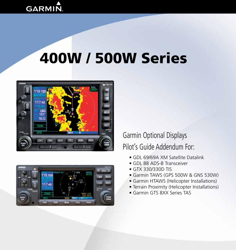

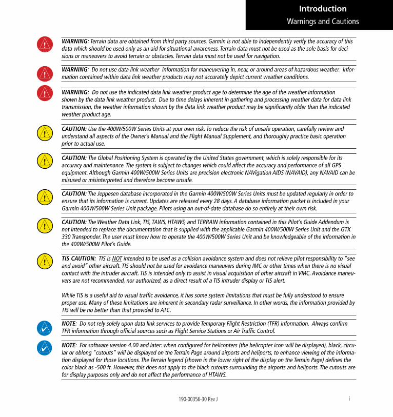


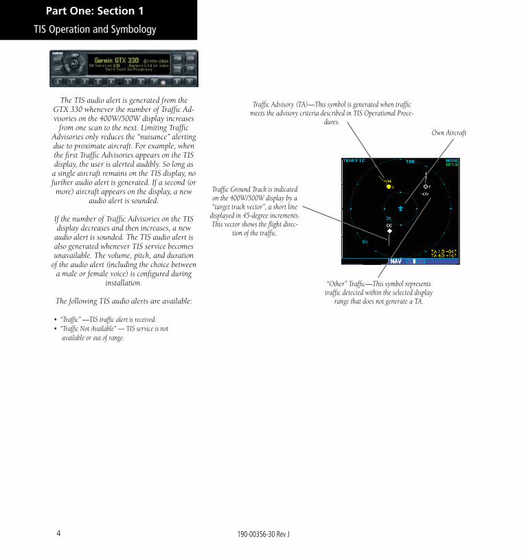


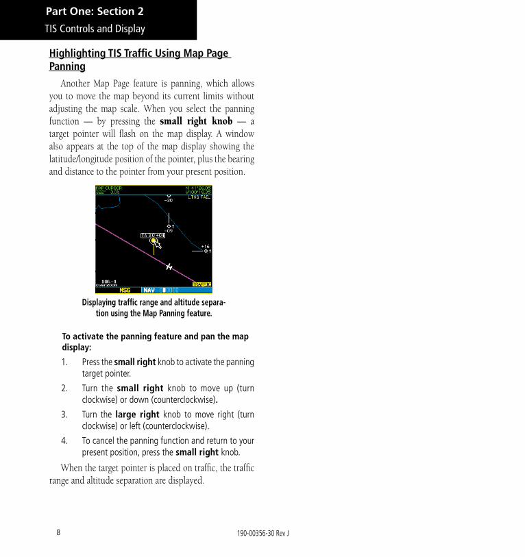
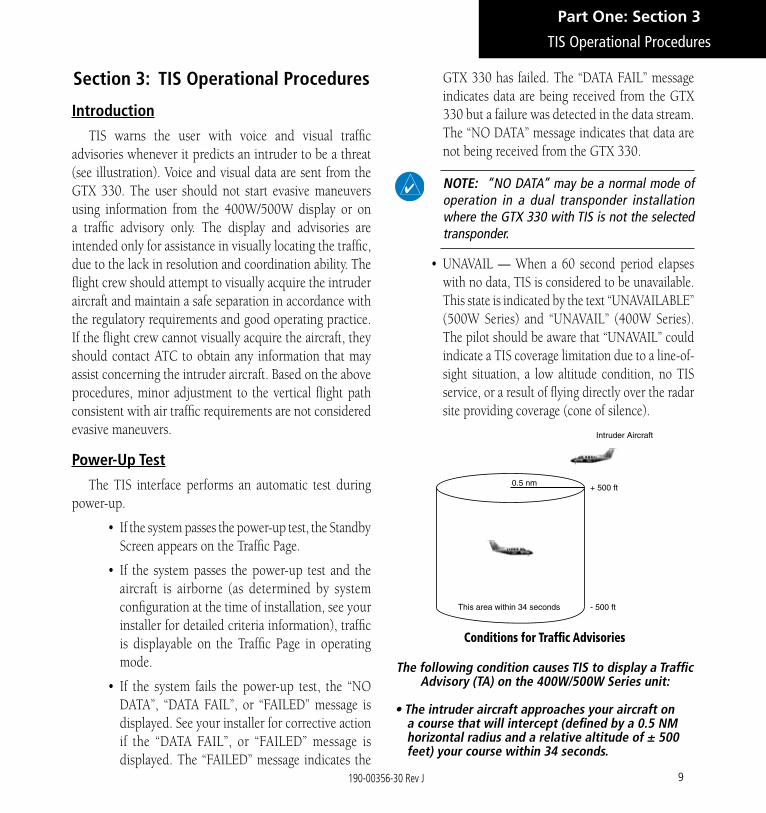
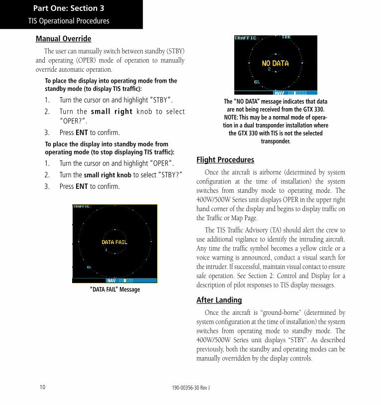


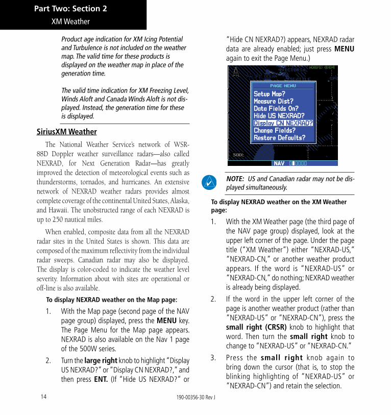
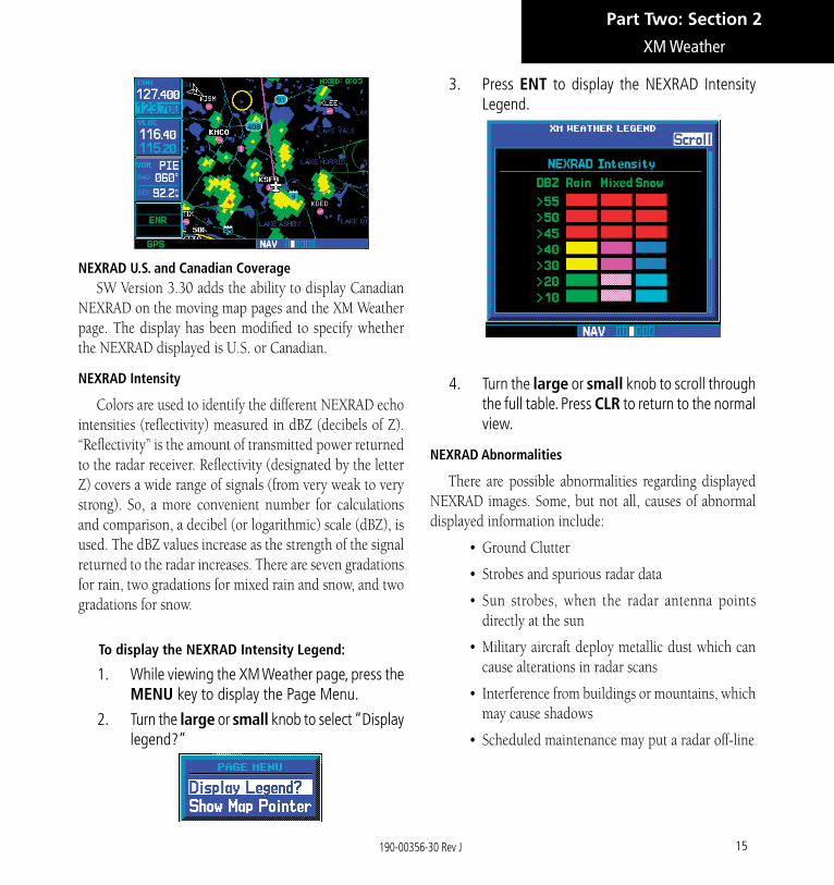

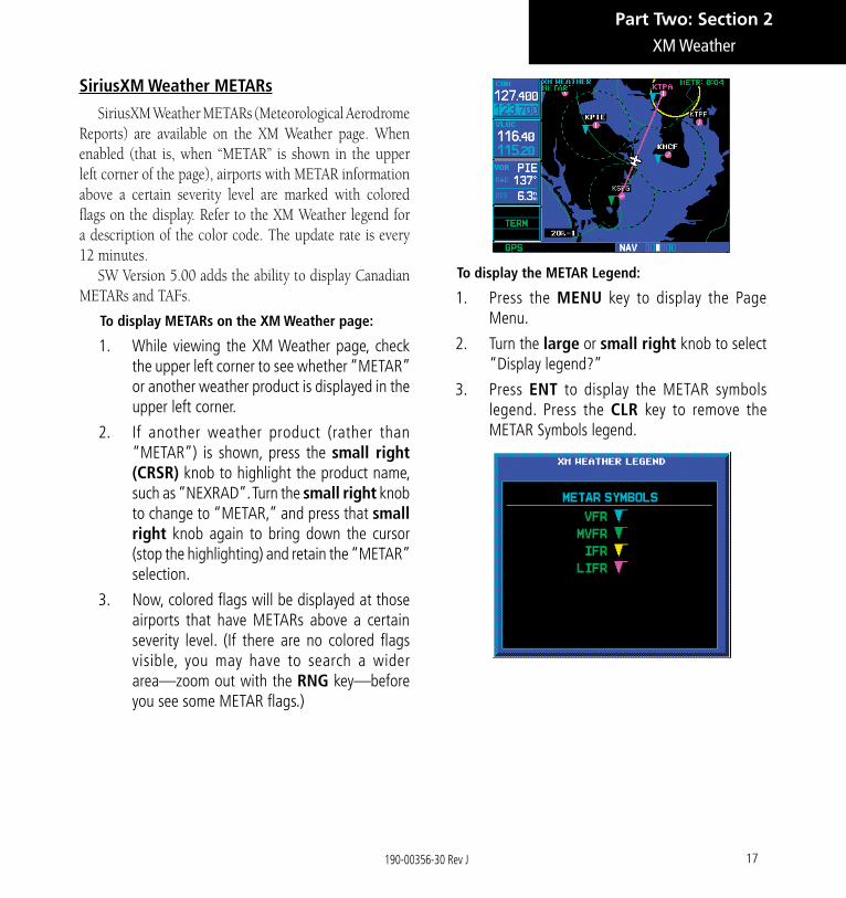
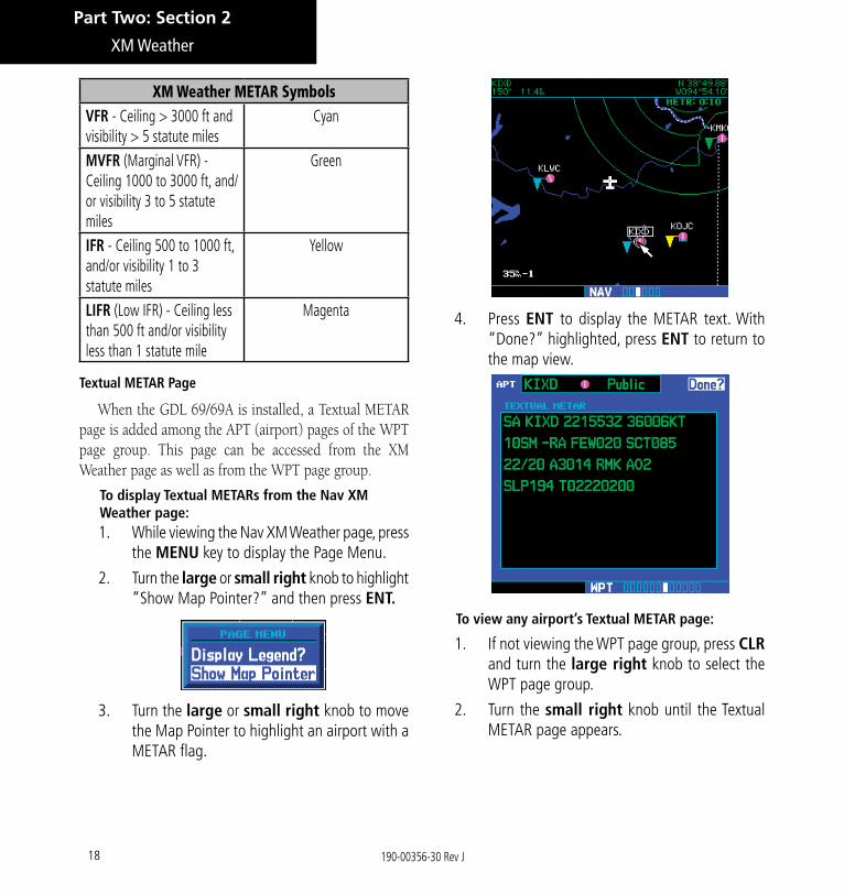
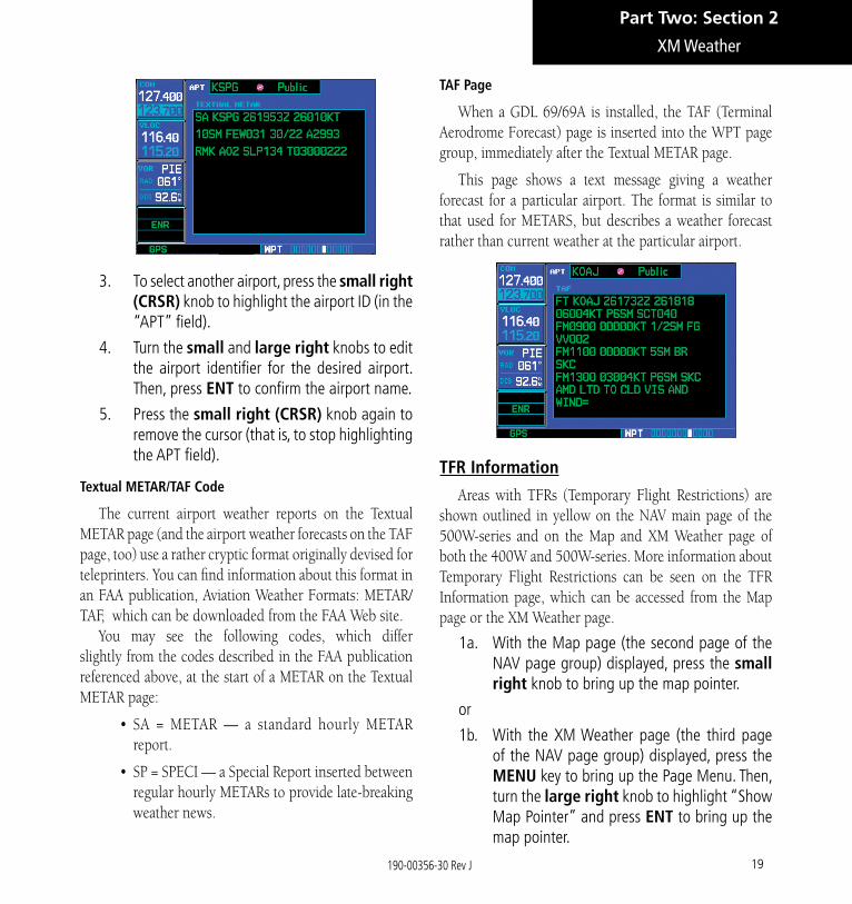
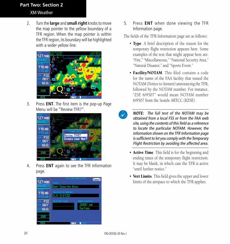


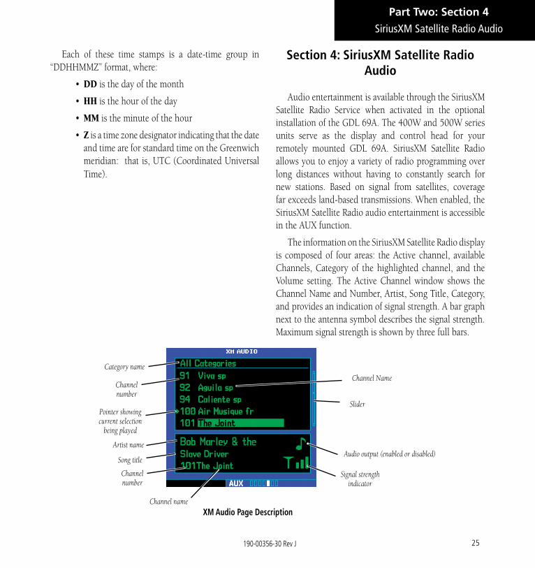
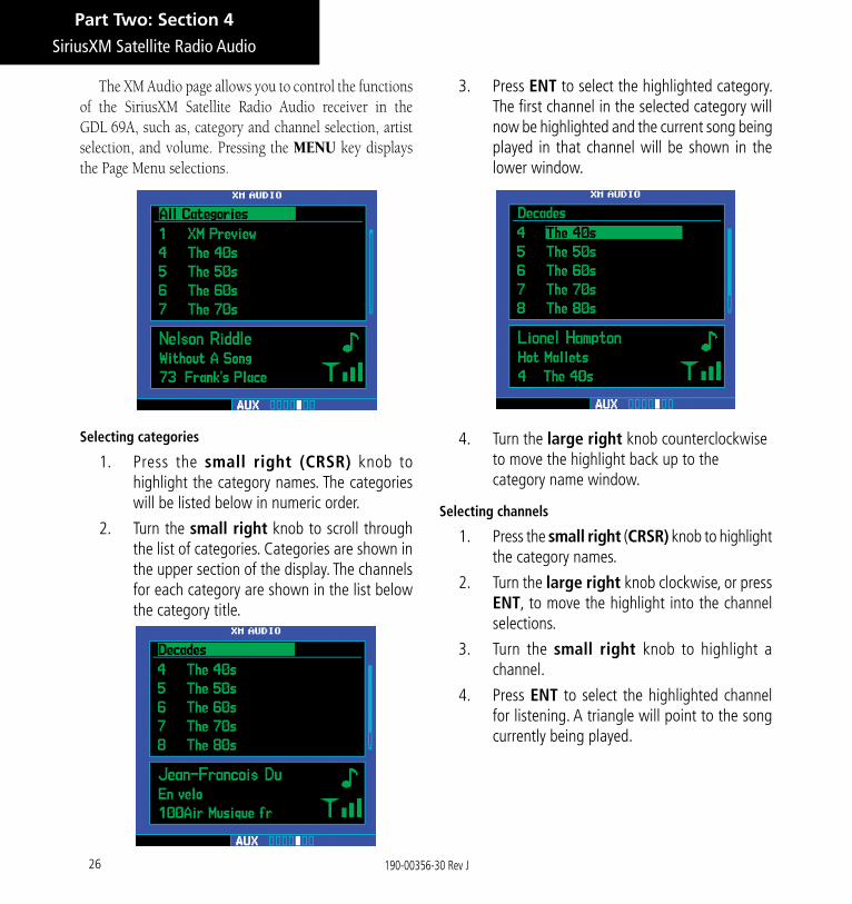
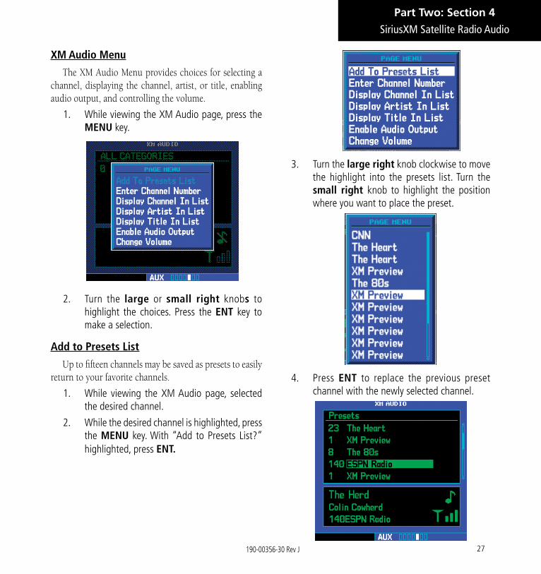
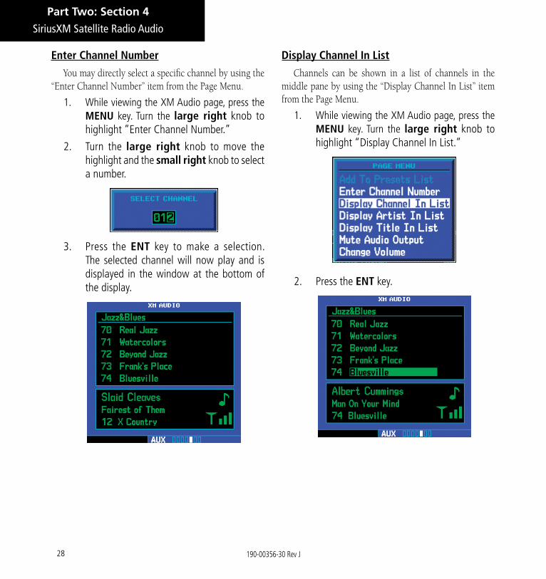


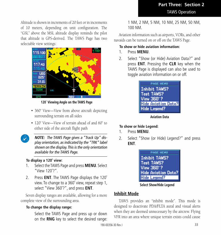


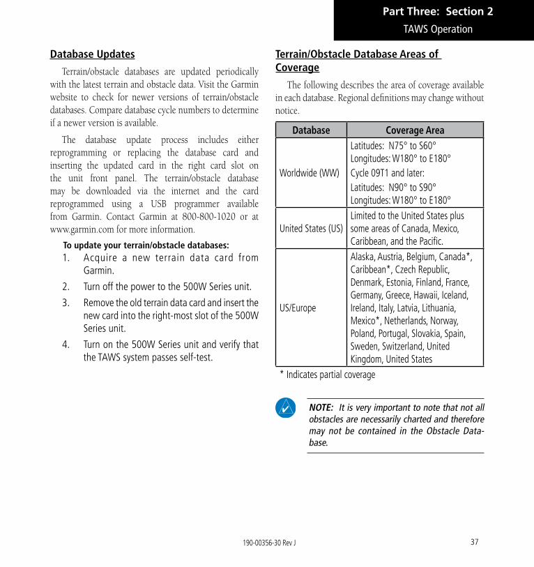


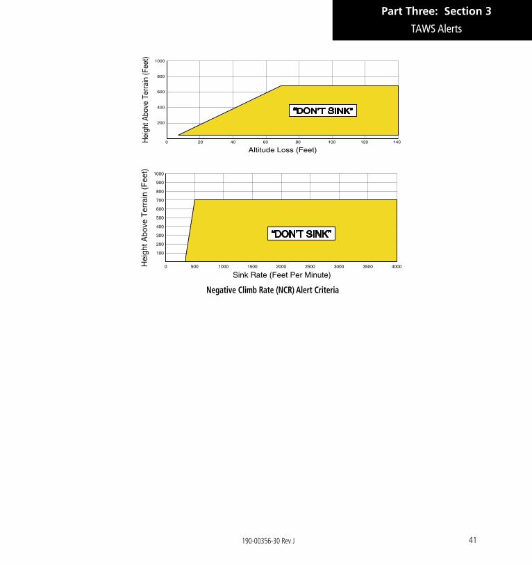


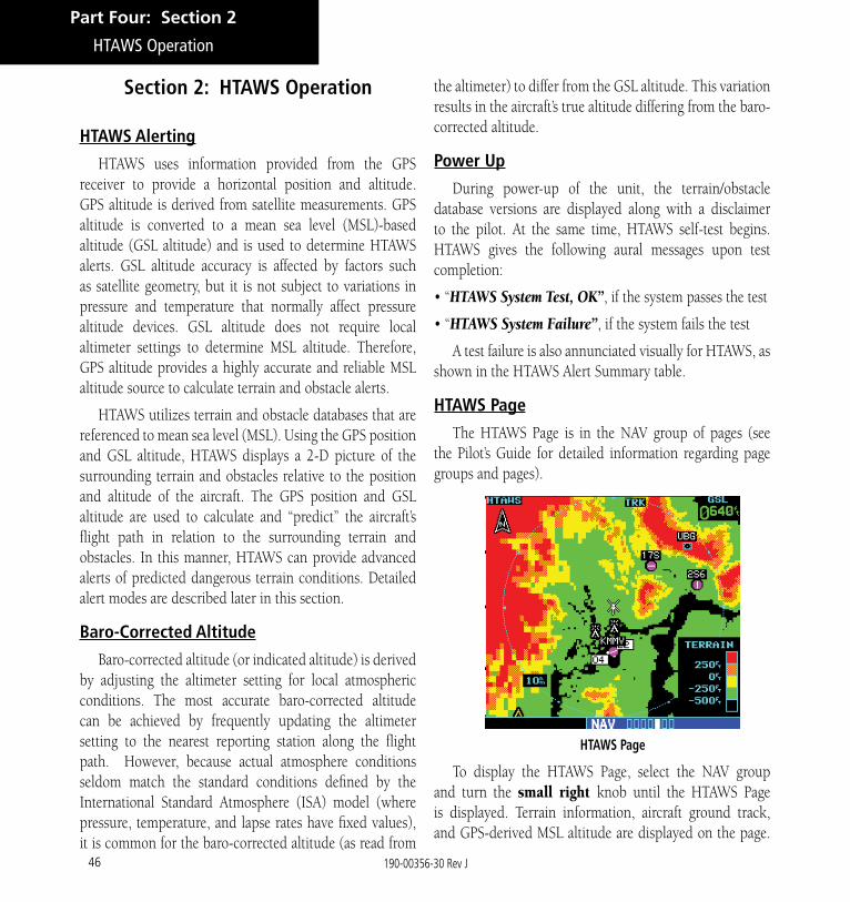

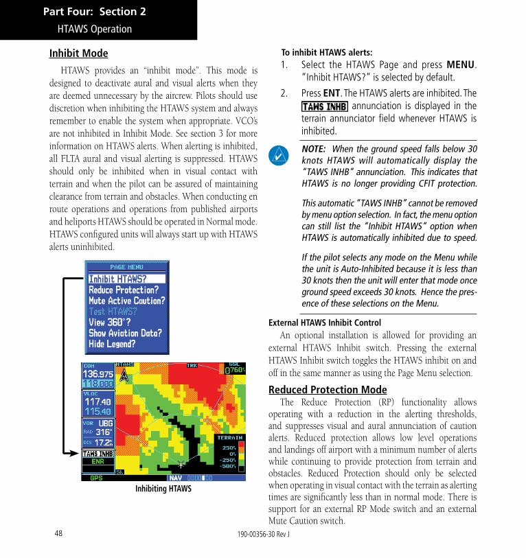

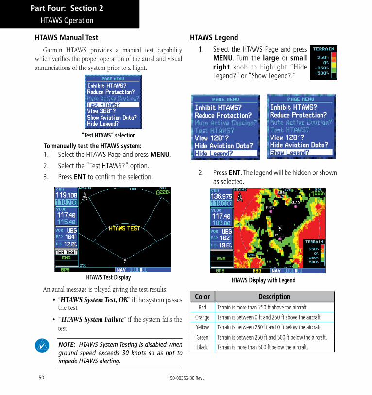

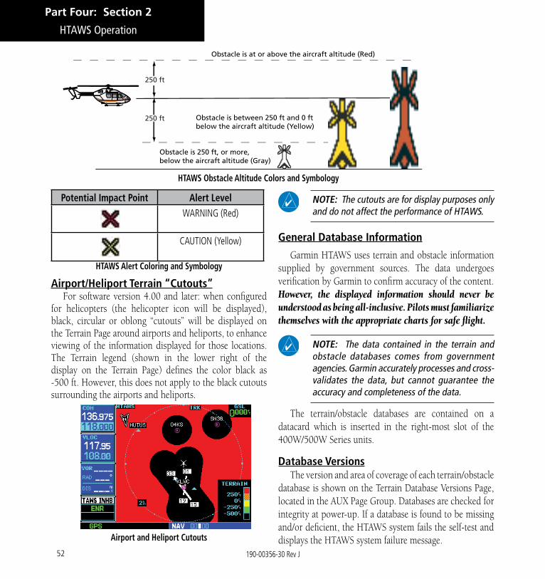
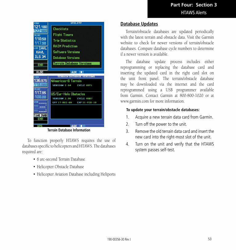

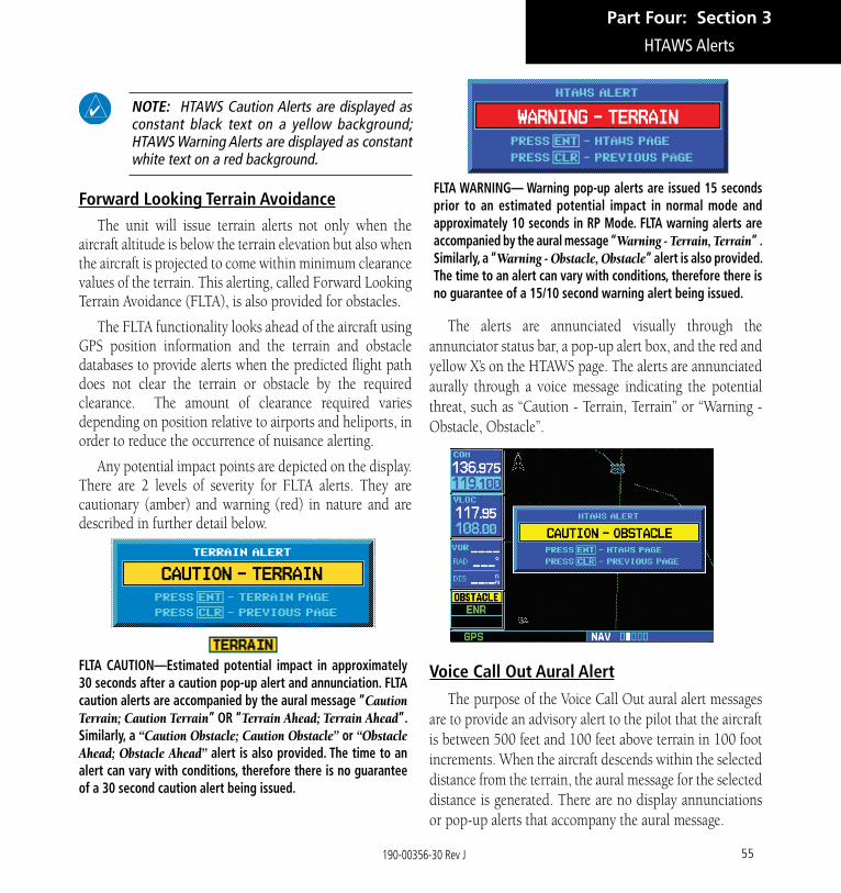
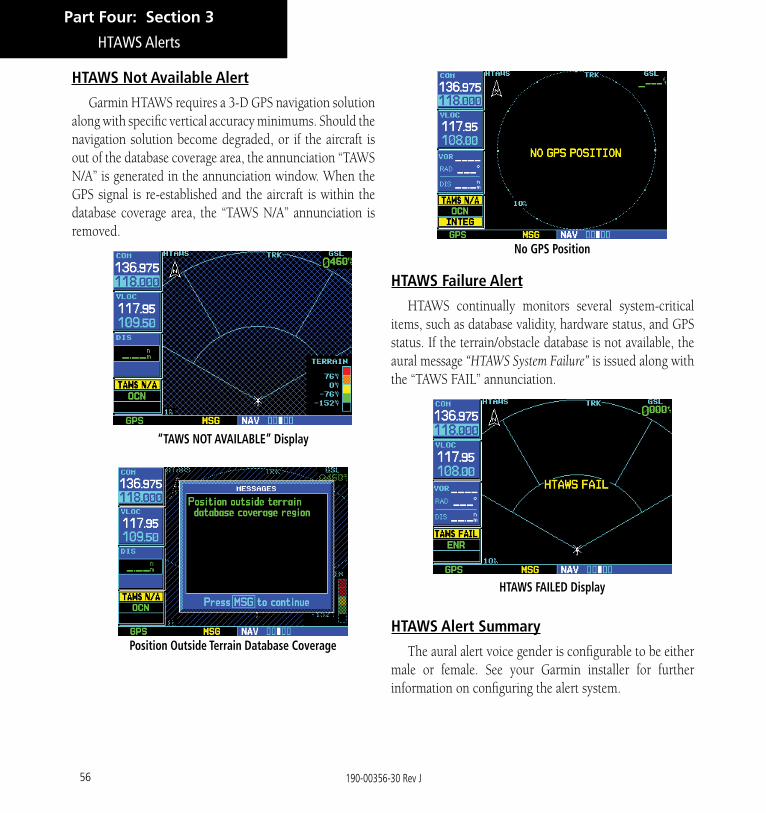

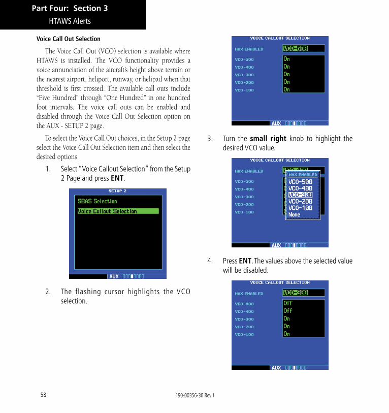


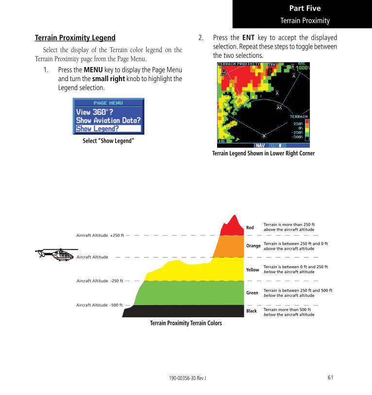

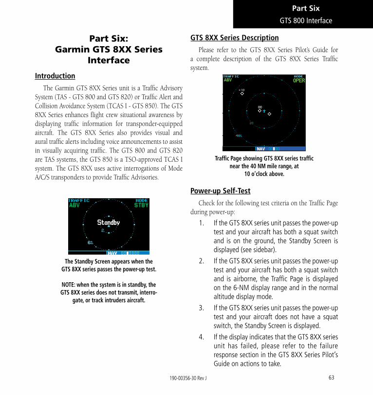


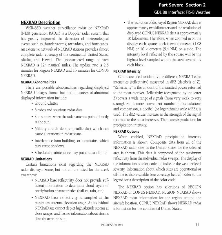
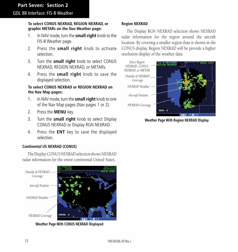
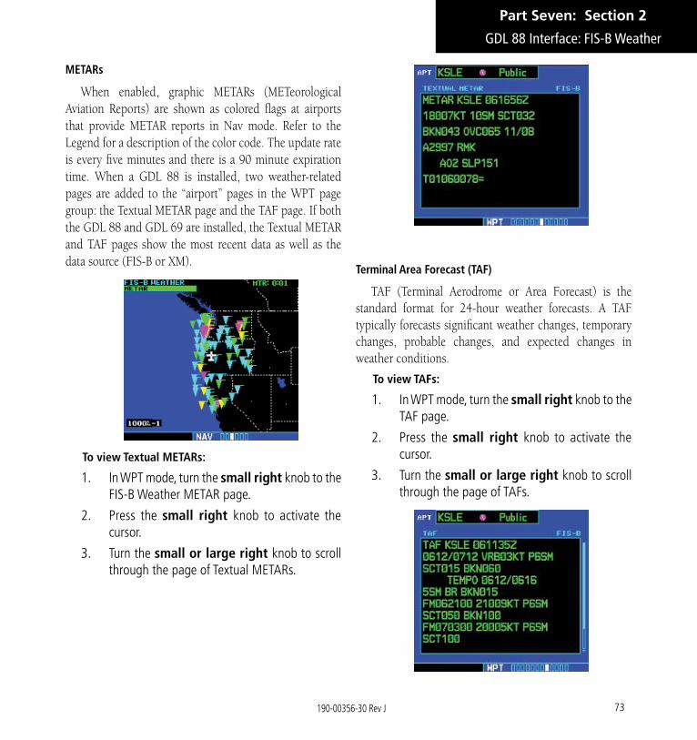

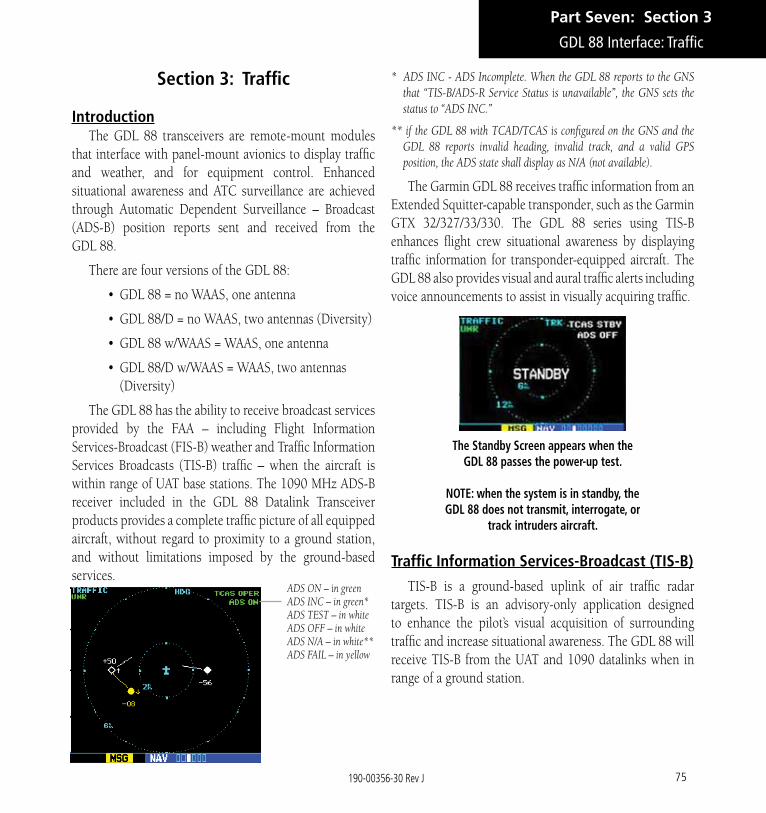
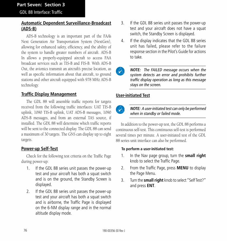

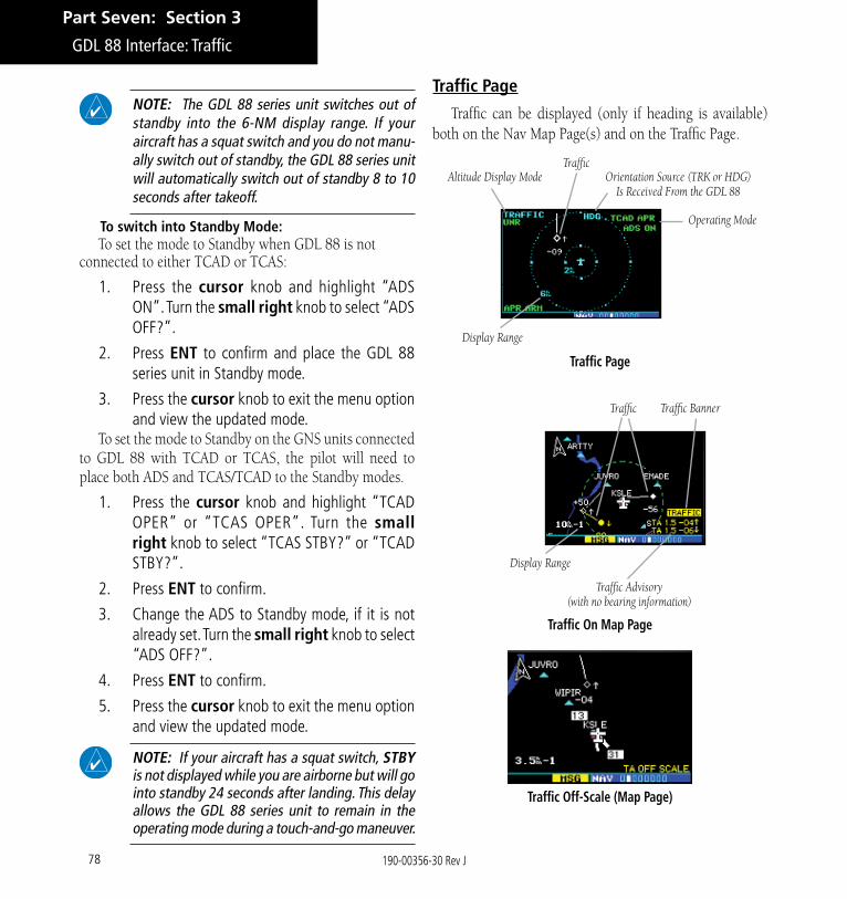
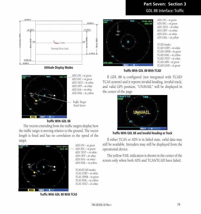
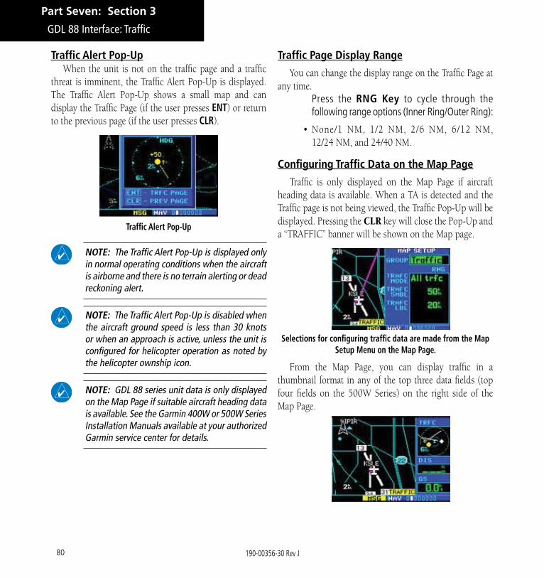
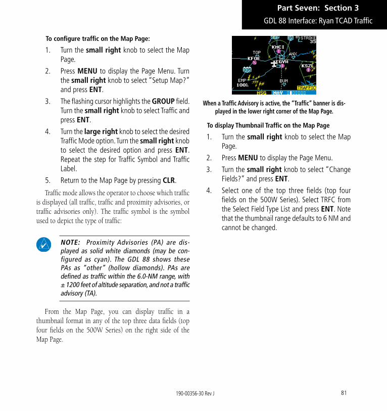

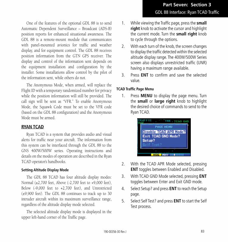


![Untitled-1 []...Power backup for common areas and 300W in I BHK, 400W in 2BHK, 500W in 3BHK apartments General amenities: Landscape on suitable open spaces & pavements with paver blocks](https://static.documents.pub/doc/80x56/5f3f0d80adb43b70f706ae90/untitled-1-power-backup-for-common-areas-and-300w-in-i-bhk-400w-in-2bhk.jpg)


![IP66 IK10 5YEARS flood light.pdf · LED FLOOD LIGHT HD-FL03-400W/500W/630W 480.6mm 338.63mm 545.66mm ]i( Á Píórïõïì EKs/>hD WP Wñ}(íì ...](https://static.documents.pub/doc/80x56/5f98a441cceaa613500e4c29/ip66-ik10-flood-lightpdf-led-flood-light-hd-fl03-400w500w630w-4806mm-33863mm.jpg)


