164
Fire 4100ES Fire Indicator Panel Installation & Maintenance Australian Installation & Maintenance Manual LT0350 Iss 1.5

Fire
Australian Installation Manual
4100 ES Fire Indicator Panel
Installation & Maintenance
Australian Installation & Maintenance Manual LT0350 Iss 1.5

iii
2006, 2013 Tyco Australia Pty Limited. All Rights Reserved.
All specifications and other information shown were current as of document revision date, and are subject to change without notice.
Tyco, Simplex, the Simplex logo, MAPNET II, IDNet, TrueAlarm, SmartSync, WALKTEST, MINIPLEX, and TrueAlert are trademarks of Tyco International Services AG or its affiliates in the U.S. and/or other countries. VESDA is a trademark of Xtralis. Simplex fire alarm technology is protected by the following U.S. Patent Numbers: TrueAlarm analog smoke detection: 5,155,468; 5,173,683 and 5,543,777. IDNet and MAPNET II addressable communications; 4,796,025. TrueAlert addressable notification; 6,313,744 and 6,426,697. SmartSync horn/strobe control; 6,281,789.
Australian Standard AS 4428.1
ActivFire Listing Number afp1682
The 4100ES is a Fire Indicator Panel manufactured for Tyco Fire Protection Products:
Tyco Fire Protection Products 47 Gilby Road Mt Waverley VIC 3149 AUSTRALIA Phone : 1300 725 688 Fax : 1300 720 733
Name Serial # Manufacture Date
Copyrights and Trademarks
Approvals
Manufacture
Product / Site

iv
Tyco (THE COMPANY) and the User of this/these document(s) desire to share proprietary technical information concerning electronic systems. For this reason the company is disclosing to the User information in the form of this/these document(s). In as much as the company considers this information to be proprietary and desires that it be maintained in confidence, it is hereby agreed by the User that such information shall be maintained in confidence by the User for a period of TEN YEARS after the issue date and only be used for the purpose for which it was supplied. During this period, the User shall not divulge such information to any third party without the prior written consent of the company and shall take reasonable efforts to prevent any unauthorised disclosure by its employees. However, the User shall not be required to keep such information in confidence if it was in their possession prior to its receipt from the company; if it is or becomes public knowledge without the fault of the User; or the information becomes available on an unrestricted basis from a third party having a legal right to disclose such information. The User's receipt and retention of this information constitutes acceptance of these terms. This information is copyright and shall not be reproduced in any form whatsoever.
The 4100ES Fire Alarm System provides a configuration programming facility, which may be accessed via a programming computer using a “dongle”. Because this programming facility allows the user to define in detail the operation of the 4100ES System being customised, changes may be made by the user that prevent this installation from meeting statutory requirements. The Company, therefore cannot accept any responsibility as to the suitability of the functions generated by the user using this programming facility.
Non-Disclosure Agreement
End User Liability Disclaimer
v
This manual applies to product with the following: Model number : 4100ES Firmware revision : 1.02.04 and on
Document Name : LT0350 4100ES Installation & Maintenance Manual
Issue : 1.5 25 Feb, 2015
14 May, 2004 Issue 1.0.6 Original based on 574-848 Rev G 16 June, 2005 Issue 1.0.7 Added Tyco 614 detectors to Appendix F 30 Oct, 2005 Issue 1.0.8 Added System Sensor detector 885WP-B to List of
Approved Devices in Appendix F. 6 October 2006
Issue 1.0.9 References to LT0432 and 1976-181 Wiring Diagrams added.
30 Nov. 2006 Issue 1.0.10 Updated drawings 1976-181 Sheets 102, 203, 500. 23 Jan. 2007 Issue 1.0.11 Clarification to RUI cabling limits (Chapter 3),
Checking wiring (Appendix C), T-GEN connection. 9 Aug. 2012 Issue 1.2 Changes for 4100ES introduction. 3-Oct-13 Issue 1.3 Changes for InfoAlarm display introduction 29-Jan-15 25-Feb-15
Issue 1.4 Issue 1.5
Battery charger adjustment updated. Updated drawing 1976-174 sheet 1.
Model Number & Firmware Revision
Document
Amendment Log
vi
READ AND SAVE THESE INSTRUCTIONS. Follow the instructions in this installation manual. These instructions must be followed to avoid damage to this product and associated equipment. Product operation and reliability depends upon proper installation. DO NOT INSTALL ANY SIMPLEX® PRODUCT THAT APPEARS DAMAGED. Upon unpacking your Simplex product, inspect the contents of the carton for shipping damage. If damage is apparent, immediately file a claim with the carrier and notify your Simplex product supplier. SAFETY HAZARD - The 4100ES CPU Card includes a lithium battery. There is danger of explosion if the battery is incorrectly replaced. Replace only with the same or equivalent type recommended by the manufacturer. Dispose of used batteries according to the manufacturer’s instructions. ELECTRICAL HAZARD - Disconnect electrical field power when making any internal adjustments or repairs. All repairs should be performed by a representative or authorized agent of your local Simplex product supplier. STATIC HAZARD - Static electricity can damage components. Therefore, handle as follows: Ground yourself before opening or installing components (use the 553-484 Static
Control Kit). Prior to installation, keep components wrapped in anti-static material at all times. EYE SAFETY HAZARD - Under certain fibreoptic application conditions, the optical output of this device may exceed eye safety limits. Do not use magnification (such as a microscope or other focusing equipment) when viewing the output of this device. RADIO FREQUENCY ENERGY - This equipment generates, uses, and can radiate radio frequency energy and if not installed and used in accordance with the instruction manual, may cause interference to radio communications. It has been tested and found to comply with the limits defined in AS 4428.0-1997 and Amendment 1 : 2002. CLASS A PRODUCT – In a domestic environment this product may cause radio interference. In which case the user may be required to take adequate measures. SYSTEM REACCEPTANCE TEST AFTER SOFTWARE CHANGES - To ensure proper system operation, this product must be tested in accordance with AS 1670 after any programming operation or change in site-specific software. Reacceptance testing is required after any change, addition or deletion of system components, or after any modification, repair or adjustment to system hardware or wiring. All components, circuits, system operations, or software functions, known to be affected by a change must be 100% tested. In addition, to ensure that other operations are not inadvertently affected, at least 10% of initiating devices that are not directly affected by the change, up to a maximum of 50 devices, should also be tested and proper system operation verified. IMPORTANT: Verify 4100ES System Programmer, Executive, and Slave Software compatibility when installing or replacing system components. Refer to Solution Bulletin SB11002 for compatibility information.
Cautions, Warnings, and Regulatory Information
vii
Copyrights and Trademarks ......................................................................................... iii
Approvals ..................................................................................................................... iii
Manufacture .................................................................................................................. iii
Product / Site ................................................................................................................ iii
Non-Disclosure Agreement ........................................................................................... iv
End User Liability Disclaimer ........................................................................................ iv
Model Number & Firmware Revision ............................................................................. v
Document ...................................................................................................................... v
Amendment Log ............................................................................................................ v
Cautions, Warnings, and Regulatory Information .......................................................... vi
Table of Contents ........................................................................................................ vii
List of Figures .............................................................................................................. xv
List of Tables .............................................................................................................. xvi
Chapter 1 Introduction to the 4100ES Fire Alarm System .............. 1
Introduction ............................................................................................................... 1 In this Chapter .......................................................................................................... 1
System Configurations .................................................................................................. 1 Overview ................................................................................................................... 1
Standalone Configuration ............................................................................................. 2 Overview ................................................................................................................... 2 System Design .......................................................................................................... 2
MINIPLEX/RTU Configuration ...................................................................................... 3 Overview ................................................................................................................... 3 System Design .......................................................................................................... 3 RUI Communication .................................................................................................. 4
Network Configuration .................................................................................................. 5 Overview ................................................................................................................... 5 Hub and Star Configurations ..................................................................................... 5 Connecting Loops ..................................................................................................... 6 System Design .......................................................................................................... 6 Network Communication ........................................................................................... 6
Glossary ....................................................................................................................... 7
Chapter 2 Installing 4100ES FIP Components ................................. 2-1
Introduction ............................................................................................................ 2-1 In this Chapter ....................................................................................................... 2-1
Introduction to FIPs (4100ES).................................................................................... 2-2 Overview ................................................................................................................ 2-2 CPU Bay ................................................................................................................ 2-2
Table of Contents XE "Table of Contents"
viii
Master Motherboard .............................................................................................. 2-3 CPU Card .............................................................................................................. 2-4 Additional Modules ................................................................................................ 2-4 CPU Card LEDs ..................................................................................................... 2-5 Operator Interface .................................................................................................. 2-6 System Power Supply (SPS) ................................................................................. 2-7 System Power ........................................................................................................ 2-8 The Power Distribution Interface (PDI) .................................................................. 2-8
Step 1. Mounting Cabinets (4100ES) ........................................................................ 2-9 Overview ................................................................................................................ 2-9
Step 2. Mounting Card Bays to Cabinets (4100ES) ................................................... 2-9 Overview ................................................................................................................ 2-9 Front Mounting Bays .............................................................................................. 2-9 Rear Mounting Bays ............................................................................................ 2-10
Step 3. Configuring Cards (4100ES) ....................................................................... 2-11 Overview .............................................................................................................. 2-11 Master Motherboard Configuration ...................................................................... 2-11 CPU Card Configuration ...................................................................................... 2-11 SPS Configuration ............................................................................................... 2-11 PDI Configuration ................................................................................................ 2-12 Configuring Other Cards ...................................................................................... 2-12
Step 4. Interconnecting Modules and Bays .............................................................. 2-12 Overview .............................................................................................................. 2-12 Guidelines ............................................................................................................ 2-12 Card Interconnections in the CPU Bay ................................................................ 2-13 Card Interconnections Within Expansion Bays .................................................... 2-13 Basic Bay-To-Bay Interconnections ..................................................................... 2-13 Connecting to Motherboards ................................................................................ 2-14
Step 5. Installing Modules into Expansion Bays (4100ES) ....................................... 2-16 Overview .............................................................................................................. 2-16 Placement Guidelines .......................................................................................... 2-16 Installing 4” X 5” Cards ........................................................................................ 2-19
Step 6. Installing LED/Switch Modules into Expansion Bays (4100ES) ................... 2-21 Overview .............................................................................................................. 2-21 The LED/Switch User Interface ............................................................................ 2-21 LED/Switch Controller Card ................................................................................. 2-21 LED/Switch Modules ............................................................................................ 2-22 Configuring the LED/Switch Controller Card ........................................................ 2-22 Activating the Communication Loss Feature ........................................................ 2-22 Mounting LED/Switch Modules to the Expansion Bay .......................................... 2-23 Mounting the Controller Card Assembly............................................................... 2-24 Changing Display Card LEDs .............................................................................. 2-24 Interconnecting Cards .......................................................................................... 2-25 Wiring Instructions ............................................................................................... 2-26
Chapter 3 Installing 4100ES MINIPLEX/RTU Components ............. 3-1
Introduction ............................................................................................................ 3-1 In this Chapter ....................................................................................................... 3-1
Introduction to MINIPLEX Transponders (4100ES) ................................................... 3-2 Overview ................................................................................................................ 3-2 Transponder Cabinets ........................................................................................... 3-2 Transponder Interface Cards (TICs) ...................................................................... 3-2 Basic TIC ............................................................................................................... 3-2 Card Specifications ................................................................................................ 3-3
ix
MINIPLEX System Guidelines (4100ES) ................................................................... 3-4 Overview ................................................................................................................ 3-4 Guidelines .............................................................................................................. 3-4
Configuring Cards (4100ES) ...................................................................................... 3-5 Overview ................................................................................................................ 3-5 CPU Motherboard DIP Switch ............................................................................... 3-5 TIC Configuration ................................................................................................... 3-5 Configuring Other Cards ........................................................................................ 3-5
TIC/Riser Mounting (4100ES) .................................................................................... 3-6 Overview ................................................................................................................ 3-6 Mounting Instructions ............................................................................................. 3-6
TIC/Motherboard Interconnections (4100ES) ............................................................ 3-7
RUI Wiring (4100ES) ................................................................................................. 3-8 Overview ................................................................................................................ 3-8 Wiring Configurations............................................................................................. 3-8 Figure 3-4 The Ferrite Bead .................................................................................. 3-8
Chapter 4 Networking ......................................................................... 4-1
Introduction ............................................................................................................ 4-1 In this Chapter ....................................................................................................... 4-1
Getting Started .......................................................................................................... 4-2 Overview ................................................................................................................ 4-2
Introduction to the 4100 Network Interface Card (NIC) .............................................. 4-2 Overview ................................................................................................................ 4-2 Network Interface Card .......................................................................................... 4-3 NIC Card LED Indications ...................................................................................... 4-3 NIC Media Cards ................................................................................................... 4-4 Requirements and Limitations ............................................................................... 4-5
Step 1. Configuring Network Cards ........................................................................... 4-5 Motherboard Jumper Settings ............................................................................... 4-5 NIC Card Address Setting ..................................................................................... 4-5 NIC Card Jumper Settings .................................................................................... 4-6 Wired Media Card Jumper Settings ...................................................................... 4-6
Step 2. Mounting Media Cards to the NIC ................................................................. 4-7 Overview ................................................................................................................ 4-7 Media Card Mounting ............................................................................................ 4-7
Step 3. Mounting Network Cards ............................................................................... 4-8
Step 4. Wiring Network Cards.................................................................................... 4-9 Overview ................................................................................................................ 4-9 Wiring Guidelines ................................................................................................... 4-9 Wiring Distances .................................................................................................. 4-10 Related Documentation ....................................................................................... 4-10 Fiber-Optic Wiring ................................................................................................ 4-11 Fiber Optic Connection Types ............................................................................. 4-11 4190-9010 Coupler Requirements ....................................................................... 4-12 Wiring with the Wired Media Card ........................................................................ 4-13 Loop Wiring, mixed Fibre and Cable .................................................................... 4-15
Chapter 5 The System Power Supply & Alarm Relay Card ............ 5-1
Introduction ............................................................................................................ 5-1
x
In this Chapter ....................................................................................................... 5-1
SPS Specifications .................................................................................................... 5-2 Input/Output/BatterySpecifications ......................................................................... 5-2 SPS Current Consumption ..................................................................................... 5-3 Environmental Requirements ................................................................................. 5-4
SPS Configuration ..................................................................................................... 5-4 Overview ................................................................................................................ 5-4 Jumper Settings ..................................................................................................... 5-4 Setting the Device Address .................................................................................... 5-4 Adjusting Voltages ................................................................................................. 5-4
SPS LED Indications ................................................................................................. 5-5 LEDs ...................................................................................................................... 5-5
Troubleshooting an SPS ............................................................................................ 5-6 Overview ................................................................................................................ 5-6 IDNet Power Monitor Trouble................................................................................ 5-6 Extra Device .......................................................................................................... 5-6 Class A Trouble ..................................................................................................... 5-6 Earth Fault Search ................................................................................................. 5-6 Short Circuit ........................................................................................................... 5-6 Channel Fail .......................................................................................................... 5-6 No Answer/ Bad Answer ........................................................................................ 5-6 Output Abnormal .................................................................................................... 5-6
The Alarm Relay Card ............................................................................................... 5-7 Overview ................................................................................................................ 5-7 Mounting ................................................................................................................ 5-7 Configuration ......................................................................................................... 5-8 Notes ..................................................................................................................... 5-8 Warning ................................................................................................................. 5-8 Specification .......................................................................................................... 5-8
Chapter 6 SPS Field Wiring (4100ES) ............................................... 6-1
Introduction ............................................................................................................ 6-1 In this Chapter ....................................................................................................... 6-1
General Field Wiring Guidelines ................................................................................ 6-2 General Guidelines ................................................................................................ 6-2
SPS NAC Field Wiring Guidelines ............................................................................. 6-3 Overview ................................................................................................................ 6-3 Guidelines .............................................................................................................. 6-3 Class A NAC Wiring ............................................................................................... 6-4 Class B NAC Wiring ............................................................................................... 6-5
Power Supply Wiring Distances ................................................................................. 6-6 Overview ................................................................................................................ 6-6 Class A NAC Wiring Table .................................................................................... 6-6 Class B NAC Wiring Table .................................................................................... 6-7
Using T-GEN 50 with 4100ES ................................................................................... 6-8 Overview ................................................................................................................ 6-8 Powering the T-GEN 50 ......................................................................................... 6-8 Controlling a T-GEN 50 with a Relay Module ...................................................... 6-10 T-GEN 50 Setting for Relay Operation ................................................................. 6-11 Controlling a T-GEN 50 from a NAC Output ........................................................ 6-12 T-GEN 50 Settings for NAC Operation ................................................................ 6-13 Fitting an EvacuationControl ................................................................................ 6-14

xi
SPS Auxiliary Power Wiring ..................................................................................... 6-15 Overview .............................................................................................................. 6-15 Guidelines ............................................................................................................ 6-15 Wiring .................................................................................................................. 6-16
SPS Relay Wiring .................................................................................................... 6-17 Overview .............................................................................................................. 6-17 Aux 1 Relay ......................................................................................................... 6-17 Alarm Relay Card ................................................................................................ 6-17 Relays .................................................................................................................. 6-18
Chapter 7 IDNet Wiring Rules ............................................................ 7-1
Introduction ............................................................................................................ 7-1 In this Chapter ....................................................................................................... 7-1
IDNet Ports in 4100ES ............................................................................................... 7-2 Overview ................................................................................................................ 7-2 IDNet Port Characteristics ..................................................................................... 7-2
Wiring to IDNet Devices ............................................................................................. 7-3 Overview ................................................................................................................ 7-3 Guidelines .............................................................................................................. 7-3 Notes ..................................................................................................................... 7-4 Class A Wiring ....................................................................................................... 7-5 Class B Wiring ....................................................................................................... 7-6
Troubleshooting IDNet Faults .................................................................................... 7-7 Overview ................................................................................................................ 7-7 IDNet Power Monitor Trouble................................................................................ 7-7 Extra Device .......................................................................................................... 7-7 Class A Trouble ..................................................................................................... 7-7 Earth Fault Search ................................................................................................. 7-7 Short Circuit ........................................................................................................... 7-7 Channel Fail .......................................................................................................... 7-7 No Answer ............................................................................................................. 7-7 Bad Answer ........................................................................................................... 7-7 Output Abnormal .................................................................................................... 7-7
Chapter 8 Using Install Mode............................................................. 8-1
Introduction ............................................................................................................ 8-1 In this Chapter ....................................................................................................... 8-1
Adding Devices to Install Mode .................................................................................. 8-2 Adding a Single Device to Install Mode .................................................................. 8-2 Adding Multiple Devices to Install Mode................................................................. 8-3
Viewing Devices in Install Mode ................................................................................ 8-5 Viewing Contents of Install Mode list ..................................................................... 8-5
Removing Devices from Install Mode ........................................................................ 8-6 Removing Individual Devices from Install Mode ..................................................... 8-6 Removing Many Points from Install Mode .............................................................. 8-6
Chapter 9 PC Software Connections ................................................ 9-1
Introduction ............................................................................................................ 9-1 In this Chapter ....................................................................................................... 9-1
Connection and Modes .............................................................................................. 9-2
xii
Overview ................................................................................................................ 9-2 Connections and Modes ........................................................................................ 9-2
Chapter 10 Australian Version Specifics.......................................... 10-1
Introduction .......................................................................................................... 10-1 In this Chapter ..................................................................................................... 10-1
Summary of Australian Version Specifics ................................................................ 10-2 Overview .............................................................................................................. 10-2 AS 4428 Requirements ........................................................................................ 10-2
Australian Panel Format .......................................................................................... 10-3 Overview .............................................................................................................. 10-3 Australian / USA Differences ............................................................................... 10-3 4100ES/4100A Differences .................................................................................. 10-3
4100ES Fan Control Module ................................................................................... 10-4 Overview .............................................................................................................. 10-4 Labeling ............................................................................................................... 10-4 Mounting & Connection ........................................................................................ 10-4 Programming ....................................................................................................... 10-4
Brigade Interfaces ................................................................................................... 10-6 Overview .............................................................................................................. 10-6 Format ................................................................................................................. 10-6 Applications ......................................................................................................... 10-6
Chapter 11 Installation Checklist, Commissioning & Maintenance ............................................................. 11-1
Introduction .......................................................................................................... 11-1 In this Chapter ..................................................................................................... 11-1
Installation Checklist ................................................................................................ 11-2 Overview .............................................................................................................. 11-2
Alignment & Adjustment .......................................................................................... 11-3 Overview .............................................................................................................. 11-3
Power Up & Placing into Operation ......................................................................... 11-4
Maintenance ............................................................................................................ 11-4
Appendix A The Device Configuration DIP Switch ......................... 1
Overview ................................................................................................................... 1
Appendix B Programming Requirements ........................................ 1
Introduction ............................................................................................................... 1 In this Chapter .......................................................................................................... 1 Required Features .................................................................................................... 1 Notes ........................................................................................................................ 1
Appendix C Checking System Wiring ............................................... 1
Overview ................................................................................................................... 1 Using the Volt/ Ohm Meter ....................................................................................... 1

xiii
Meter Readings ........................................................................................................ 2
Appendix D Earth Fault Detection ..................................................... 1
Overview ................................................................................................................... 1
General Guidelines ....................................................................................................... 2
Earth Fault Searching from the Front Panel .................................................................. 3 Overview ................................................................................................................... 3 Access Level Selection ............................................................................................. 3 Starting the Earth Fault Search ................................................................................. 3 Location Search ........................................................................................................ 4 IDNet Channel Search .............................................................................................. 5 Last Search Result ................................................................................................... 6 Completing the Search ............................................................................................. 6
Search Results ............................................................................................................. 7 Overview ................................................................................................................... 7 Non-Point Faults ....................................................................................................... 7 Point Faults ............................................................................................................... 7 Fault Not Found ........................................................................................................ 8 No Fault .................................................................................................................... 8 Result Not Available ................................................................................................. 8
Earth Fault Search Example ......................................................................................... 9
Appendix E Compatible Actuating Devices ..................................... 1
Introduction ............................................................................................................... 1 In this Chapter .......................................................................................................... 1
List of Approved Devices .............................................................................................. 1
Compatible Detectors, IDNET ....................................................................................... 4
Compatible Addressable Field Devices, IDNet ............................................................. 5
Appendix F Compatible Batteries ..................................................... 1
Appendix G 4100ES Specifications .................................................. 1
General ..................................................................................................................... 1 Fuses ........................................................................................................................ 1 Firmware Features .................................................................................................... 1
Voltage & Current Ratings of Modules & Assemblies ................................................... 2
Appendix H Power Supply & Battery Capacity Calculations ........ 1
Power Supply ............................................................................................................ 1 Battery Capacity ....................................................................................................... 1
Appendix J Cable Characteristics ..................................................... 1
IDNet ........................................................................................................................ 1 4100 MAPNET II ....................................................................................................... 1 NETWORK ............................................................................................................... 1

xiv
Appendix K List of Spare Parts ......................................................... 1
Spare Part Order Codes .......................................................................................... 1
Appendix L List of Drawings ............................................................. 1

xv
Figure 1-1. Standalone 4100ES System ........................................................................... 2 Figure 1-2. MINIPLEX/RTU 4100ES System .................................................................... 4 Figure 1-3. Star/Ring Configuration ................................................................................. 5 Figure 1-4. Interconnected Loop Configuration ................................................................ 6 Figure 2-1. Master Motherboard (566-227) ................................................................... 2-3 Figure 2-2. CPU Card (566-719) .................................................................................. 2-4 Figure 2-3. InfoAlarm Operator Interface ...................................................................... 2-6 Figure 2-4. System Power Supply ................................................................................ 2-7 Figure 2-5. The Power Distribution Interface (PDI) ........................................................ 2-8 Figure 2-6. Bracket and Bay Mounting – earlier style ................................................. 2-10 Figure 2-7. Bay Mounting – later style ......................................................................... 2-10 Figure 2-8. Bay-to-Bay Interconnections ..................................................................... 2-14 Figure 2-9. Power and Communication Wiring for Motherboards ............................... 2-15 Figure 2-10. Expansion Bay 4”x 5” Card Placement ................................................... 2-16 Figure 2-11. Expansion Bay Motherboard Placement ................................................ 2-17 Figure 2-12. Mixed Module Placement ....................................................................... 2-18 Figure 2-13. Slave Card/PDI Connection ..................................................................... 2-19 Figure 2-14. Installing the Motherboard in a 4100ES Expansion Bay .......................... 2-20 Figure 2-15. LED/Switch Modules ............................................................................... 2-21 Figure 2-16. LED/Switch Controller ............................................................................. 2-21 Figure 2-17. LED/Switch Card Mounting on a bay mounted door (earlier style) ......... 2-23 Figure 2-18. Controller Card Mounting ........................................................................ 2-24 Figure 2-19. Assembling / Disassembling the LED Display Card (pluggable LED
version, only) ........................................................................................................ 2-25 Figure 2-20. LED/Switch Controller Wiring .................................................................. 2-26 Figure 3-1. Transponder Interface Cards ....................................................................... 3-2 Figure 3-2. TIC Mounting ............................................................................................... 3-6 Figure 3-3. Transponder Cabinet Interconnections ........................................................ 3-7 Figure 3-4 The Ferrite Bead ......................................................................................... 3-8 Figure 3-5. TIC Wiring to the Host Panel ....................................................................... 3-8 Figure 4-1. 4100-6014 Network Interface Card .............................................................. 4-3 Figure 4-2. The 4100-6057 Fiber-Optic Media Card ...................................................... 4-4 Figure 4-3. The 4100-6056 Wired Media Card .............................................................. 4-4 Figure 4-4. Media Card Mounting .................................................................................. 4-7 Figure 4-5. Installing the NIC ......................................................................................... 4-8 Figure 4-6. Fiber Wiring ............................................................................................... 4-11 Figure 4-7. Coupler Wiring .......................................................................................... 4-13 Figure 4-8. Wired Media Interconnections between 4100ES Master Motherboards .... 4-14 Figure 4-9. Example of Ring/Loop NetworkWiring ....................................................... 4-15 Figure 5-1. The Alarm Relay Card ................................................................................. 5-7 Figure 6-1. The Ferrite Bead ......................................................................................... 6-2 Figure 6-2. Class A NAC Wiring .................................................................................... 6-4 Figure 6-3. Class B Wiring ............................................................................................. 6-5 Figure 7-1. Ferrite Bead Wiring ..................................................................................... 7-3 Figure 7-2. Cable Distance & Device Limits for Common Cable Sizes .......................... 7-4 Figure 7-3. Class A (loop) Wiring ................................................................................... 7-5 Figure 7-4. Class B (spur or string) Wiring ..................................................................... 7-6 Figure 8-1. Sample Fault List Display Showing a Missing Card ..................................... 8-2 Figure 8-2. MoreInfo on this Fault with Add Inst Option ................................................ 8-2 Figure 8-3. Fault List Now With Only a Single Install Mode Fault .................................. 8-3 Figure 8-4. Fault List with Additional Missing Devices ................................................. 8-3 Figure 8-5. Service/Diagnostics Option on Main Menu ................................................. 8-3 Figure 8-6. Install Mode Option on Diagnostic Menu Screen ........................................ 8-4 Figure 8-7. Add Options on the Install Mode Menu Screen .......................................... 8-4 Figure 8-8. View Option on the Install Mode Menu Screen ........................................... 8-5 Figure 8-9. Displaying Contents of Install Mode List ..................................................... 8-5 Figure 8-10. More Info on a Device in the Install Mode List .......................................... 8-6 Figure 8-11. Remove Options on the Install Mode Menu Screen .................................. 8-6
List of Figures XE "List of Figures"

xvi
Figure 9-1. Serial Connection (slower) .......................................................................... 9-2 Figure 9-2. Ethernet Connection (fast) ........................................................................... 9-2 Figure 10-1. Fan Control Module ................................................................................. 10-5 Figure A-1 Dip Switch SWx ...................................................................................... A-1 Figure D-1. Earth Fault Search Example ................................................................... D-8
Table 2-1 Master Controller LEDs 1 through 4 ............................................ 2-5 Table 3-1 TIC Specifications ....................................................................... 3-3 Table 4-1 4100 NIC & Media Cards – Electrical and Environmental Specifications .............................................................................. 4-5 Table 4-2 Wiring Distances ....................................................................... 4-10 Table 4-3 Dual Fiber Optic Cable Communications Distance Examples ... 4-12 Table 4-4 Single Fiber Optic Cable Communications Distance Examples using 4190-9010 Bi-Directional Couplers.................. 4-12 Table 4-5 566-227 CPU Motherboard Wired Media Connections .............. 4-14 Table 5-1 SPS Input and Output Specifications .......................................... 5-2 Table 5-2 SPS Current Specifications ......................................................... 5-3 Table 5-3 Alarm Relay Card Jumper Positions ............................................ 5-8 Table 6-1 Class A Wiring Distances ............................................................ 6-6 Table 6-2 Class B Wiring Distances ............................................................ 6-7 Table 6-3 T-GEN 50 Settings for Relay Operation .................................... 6-11 Table 6-4 T-GEN 50 Switch Settings for Relay Operation ......................... 6-11 Table 6-5 T-GEN 50 Link Settings for Relay Operation ............................. 6-11 Table 6-6 T-GEN 50 Settings for NAC Operation ...................................... 6-13 Table 6-7 T-GEN 50 Switch Settings for NAC Operation .......................... 6-13 Table 6-8 T-GEN 50 Link Settings for NAC Operation .............................. 6-13 Table 10-1 Switch/LED Format ................................................................... 10-4 Table 10-2 Switch Status ............................................................................ 10-4 Table A-1 Card Addresses .......................................................................... A-2 Table C-1 Acceptable Zone and Signal Circuit Meter Readings ................. C-2 Table J-1 Network: Maximum Transmission Distances, “Wired” Network ... J-1 Table J-2 Network: Maximum Distances, Optical Fibre ............................... J-2
List of Tables XE "List of Tables"
1-1
The 4100ES is an expandable fire alarm system that can be used as a standalone system with one host panel, or as a wide-ranging system with several remote cabinets, with one or more host panels. This chapter is an overview of standalone, MINIPLEX, and network 4100ES system concepts. xe "4100 Fire Alarm System"
Refer to the page number listed in this table for information on a specific topic.
Topic See Page #
System Configurations 1-1
Standalone Configuration 1-2
MINIPLEX/RTU Configuration 1-3
Network Configuration 1-5
Glossary 1-7
The 4100ES is available as a standalone system with one host panel, or as an expanded system with several remote cabinets, with one or more host panels. The type of configuration used depends on the size of the site into which it is being installed. The following types of configurations are offered: Standalone. Comprised of one FIP and its assorted warning devices, initiating devices, and signaling line circuit devices.xe "4100 Fire Alarm System: standalone (definition)"xe "Standalone 4100 Fire Alarm System: definition" MINIPLEX/Remote Transponders. A standalone system plus remote transponder cabinets, which allow for additional slave modules to be used. Typically used for multi-level buildings and small multi-building applications.xe "4100 Fire Alarm System: MINIPLEX (definition)"xe "MINIPLEX 4100 Fire Alarm System: definition" Network. A multi-FIP system connected by network cards. Each panel maintains the status and control of its own circuit points while monitoring and controlling activity at other locations. Network nodes may perform similar tasks, or may be dedicated to specific functions.xe "4100 Fire Alarm System: network (definition)"xe "Network 4100 Fire Alarm System: definition" This chapter outlines the fundamental concepts of each configuration.
Chapter 1 Introduction to the 4100ES Fire Alarm System
Introduction
In this Chapter
System Configurations
Overview
1-2
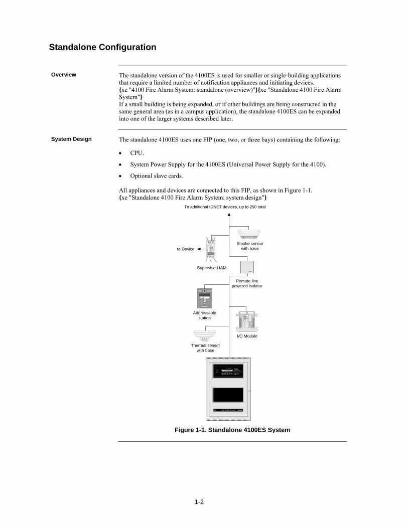
The standalone version of the 4100ES is used for smaller or single-building applications that require a limited number of notification appliances and initiating devices. xe "4100 Fire Alarm System: standalone (overview)"xe "Standalone 4100 Fire Alarm System" If a small building is being expanded, or if other buildings are being constructed in the same general area (as in a campus application), the standalone 4100ES can be expanded into one of the larger systems described later.
The standalone 4100ES uses one FIP (one, two, or three bays) containing the following:
CPU.
System Power Supply for the 4100ES (Universal Power Supply for the 4100).
Optional slave cards. All appliances and devices are connected to this FIP, as shown in Figure 1-1. xe "Standalone 4100 Fire Alarm System: system design"
ALARMFIRE
PULL DOWN
Addressablestation
I/O Module
Supervised IAM
Smoke sensorwith base
Remote linepowered isolator
To additional IDNET devices, up to 250 total
4100 FIRE ALARM CONTROL
PULL TO OPENOO EMERGENCY
OPERATINGINSTRUCTIONSALARM OR TROUBLE
- SYSTEM INDICATOR TO - PRESS "ACK" LOCATED - REPEAT OPERATION UNTIL TO SILENCE - PRESS "ALARM TO RESTORE SYSTEM - PRESS - PRESS "ACK" TO
OPERATO
INTERFAC
PANEL
TROU
SILEN
O
ALA
SYSTSUPERVI
SYSTEM IS NORMAL12:35:15 am MON 29 JAN 96
ACKNO
TBAC ALA
SIMPLEX TIME
2190-9155 .09
2190-9157 .012A
INSTAL. INSTRUC.
2190-9161 .04
2190-9163 .04
INSTAL..INSTRUC.
3333 BAUDRATE 28 VD
519-57
1 2 3 4 5
ADDRESS CO
1 2 3 4 5 6 7
A D D R E S S C O
519-63
1 2 3 4 5 6
O
Thermal sensorwith base
to Device
Figure 1-1. Standalone 4100ES System
Standalone Configuration
Overview
System Design

1-3
The MINIPLEX/Remote Transponder version of the 4100 Fire Alarm System is designed for moderately larger applications than the standalone configuration, and allows up to 1000 monitor and/or control points and 2000 annunciator points to be controlled by a single FIP. xe "4100 Fire Alarm System: miniplex (overview)"xe "Miniplex 4100 Fire Alarm System: about" Like the standalone system, only one CPU is used. Remote Unit Interface (RUI) data, and optionally power, is distributed from the host panel to the Remote Transponder Units (RTU) remote boxes called transponder cabinets. 4100ES xe "transponder interface card (TIC): definition"xe "MINIPLEX 4100 Fire Alarm System: transponder interface card (TIC)"Transponder interface cards (TICs), located in RTU cabinets, take the RUI data directly from the CPU motherboard and distribute it to the modules in the RTU cabinet.
The MINIPLEX 4100ES FIP must contain the following:
CPU.
System Power Supply for the 4100ES.
Optional slave cards. xe "MINIPLEX 4100 Fire Alarm System: system design" Each transponder cabinet must contain a Transponder Interface Card (TIC) and any number of optional slave cards.
Continued on next page
MINIPLEX/RTU Configuration
Overview
System Design
1-4
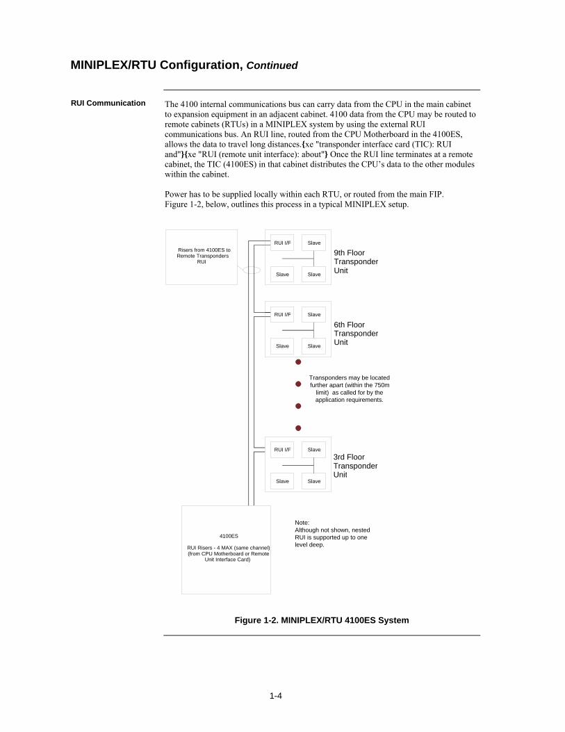
The 4100 internal communications bus can carry data from the CPU in the main cabinet to expansion equipment in an adjacent cabinet. 4100 data from the CPU may be routed to remote cabinets (RTUs) in a MINIPLEX system by using the external RUI communications bus. An RUI line, routed from the CPU Motherboard in the 4100ES, allows the data to travel long distances.xe "transponder interface card (TIC): RUI and"xe "RUI (remote unit interface): about" Once the RUI line terminates at a remote cabinet, the TIC (4100ES) in that cabinet distributes the CPU’s data to the other modules within the cabinet. Power has to be supplied locally within each RTU, or routed from the main FIP. Figure 1-2, below, outlines this process in a typical MINIPLEX setup.
Figure 1-2. MINIPLEX/RTU 4100ES System
MINIPLEX/RTU Configuration, Continued
RUI Communication
4100ES
RUI Risers - 4 MAX (same channel)(from CPU Motherboard or Remote
Unit Interface Card)
Transponders may be locatedfurther apart (within the 750m
limit) as called for by theapplication requirements.
Risers from 4100ES toRemote Transponders
RUI
9th FloorTransponderUnit
6th FloorTransponderUnit
3rd FloorTransponderUnit
RUI I/F Slave
Slave Slave
RUI I/F Slave
Slave Slave
RUI I/F Slave
Slave Slave
Note:Although not shown, nestedRUI is supported up to onelevel deep.
1-5
The 4100ES can be expanded to become a network system by using network interface cards (NICs). When a NIC is installed into a 4100ES host panel, it is used to connect to other network nodes. Nodes may be other host 4100 panels, or they may be other things such as Graphical Command Centers (GCCs), and Visual Command Centers (VCCs). A node is a self-sufficient CPU that controls appliances and devices, which also has the capability of controlling and communicating with other nodes.
xe "4100 Fire Alarm System: network (overview)"xe "Network 4100 Fire Alarm System: about"
xe "Network 4100 Fire Alarm System: hub configuration"xe "Network 4100 Fire Alarm System: ring configuration"xe "Network 4100 Fire Alarm System: star configuration"xe "hub configuration"xe "ring configuration"xe "star configuration"The network configuration supports two basic architectures (or wiring configurations): ring or star. A networked system can also use a combination of the two.
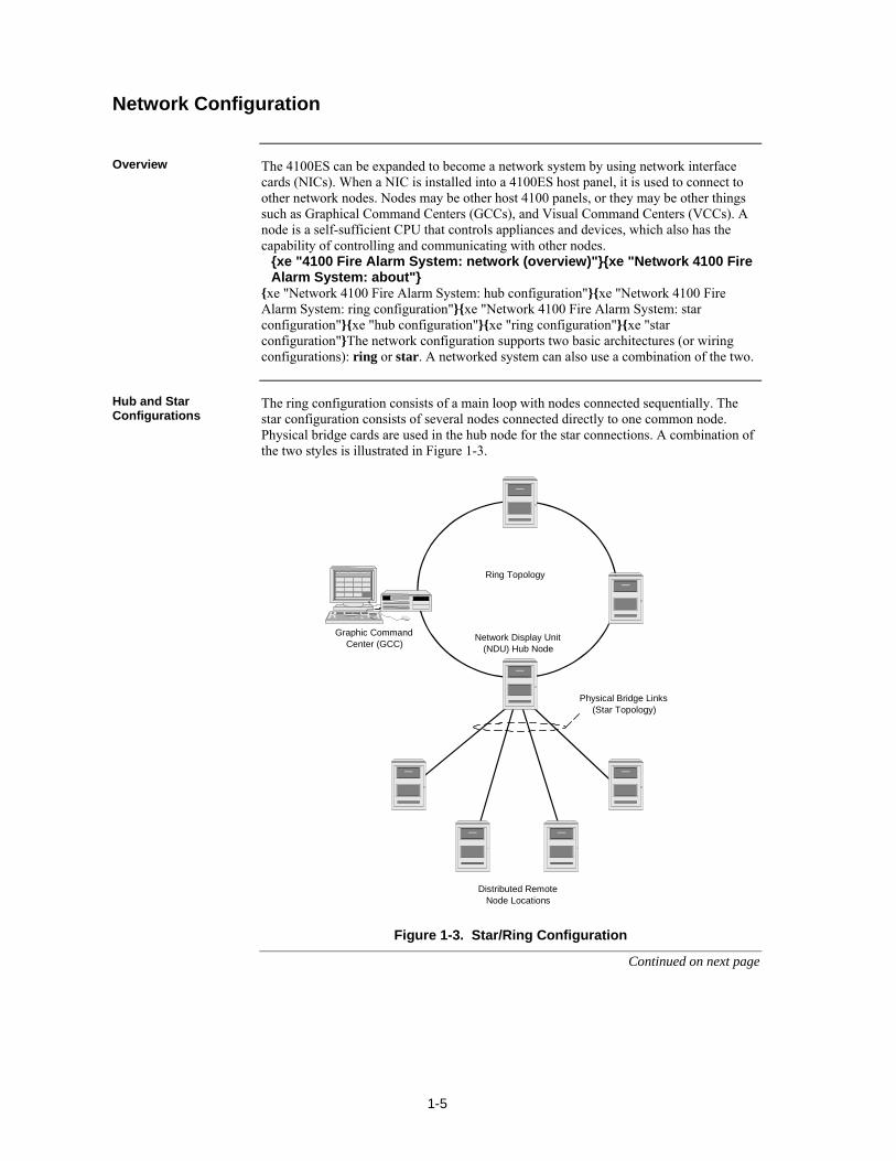
The ring configuration consists of a main loop with nodes connected sequentially. The star configuration consists of several nodes connected directly to one common node. Physical bridge cards are used in the hub node for the star connections. A combination of the two styles is illustrated in Figure 1-3.
Ring Topology
Physical Bridge Links (Star Topology)
Graphic CommandCenter (GCC)
Network Display Unit(NDU) Hub Node
Distributed RemoteNode Locations
Figure 1-3. Star/Ring Configuration
Continued on next page
Network Configuration
Overview
Hub and Star Configurations
1-6
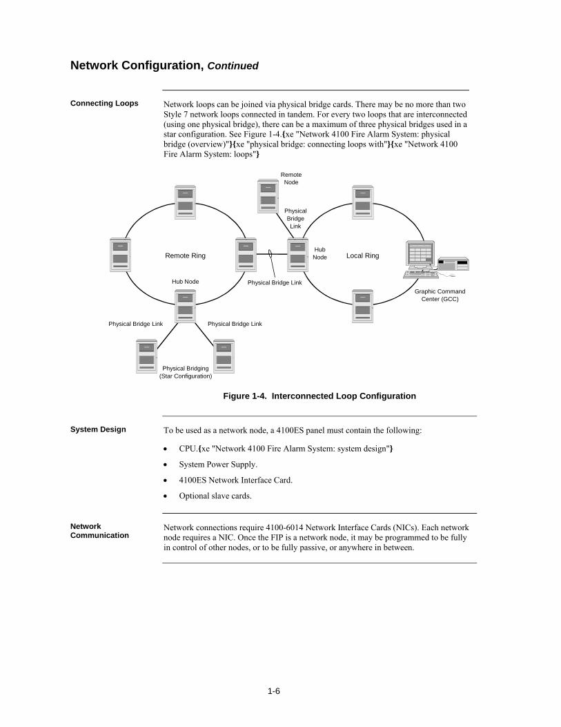
Network loops can be joined via physical bridge cards. There may be no more than two Style 7 network loops connected in tandem. For every two loops that are interconnected (using one physical bridge), there can be a maximum of three physical bridges used in a star configuration. See Figure 1-4.xe "Network 4100 Fire Alarm System: physical bridge (overview)"xe "physical bridge: connecting loops with"xe "Network 4100 Fire Alarm System: loops"
Remote Ring
Physical Bridge Link
Local Ring
Physical Bridging(Star Configuration)
Graphic CommandCenter (GCC)
PhysicalBridgeLink
Physical Bridge Link
Hub Node
HubNode
RemoteNode
Physical Bridge Link
Figure 1-4. Interconnected Loop Configuration
To be used as a network node, a 4100ES panel must contain the following:
CPU.xe "Network 4100 Fire Alarm System: system design"
System Power Supply.
4100ES Network Interface Card.
Optional slave cards.
Network connections require 4100-6014 Network Interface Cards (NICs). Each network node requires a NIC. Once the FIP is a network node, it may be programmed to be fully in control of other nodes, or to be fully passive, or anywhere in between.
Network Configuration, Continued
Connecting Loops
System Design
Network Communication
1-7
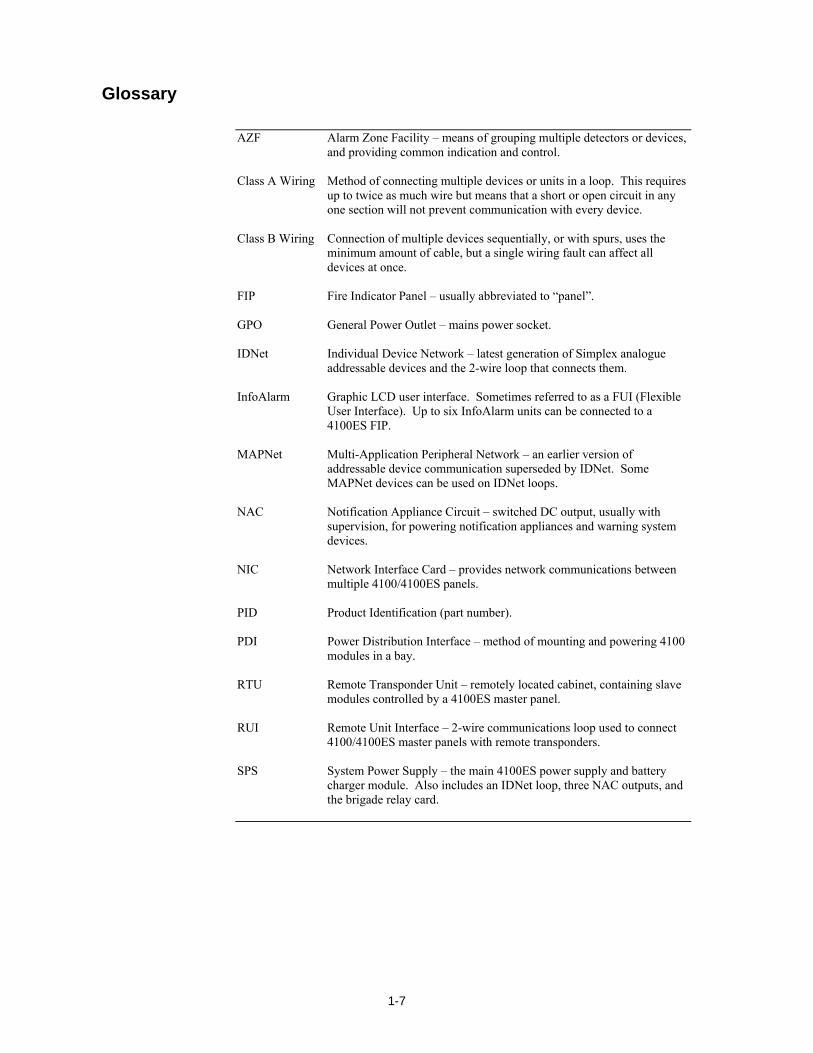
AZF Alarm Zone Facility – means of grouping multiple detectors or devices,
and providing common indication and control. Class A Wiring Method of connecting multiple devices or units in a loop. This requires
up to twice as much wire but means that a short or open circuit in any one section will not prevent communication with every device.
Class B Wiring Connection of multiple devices sequentially, or with spurs, uses the
minimum amount of cable, but a single wiring fault can affect all devices at once.
FIP Fire Indicator Panel – usually abbreviated to “panel”. GPO General Power Outlet – mains power socket. IDNet Individual Device Network – latest generation of Simplex analogue
addressable devices and the 2-wire loop that connects them. InfoAlarm Graphic LCD user interface. Sometimes referred to as a FUI (Flexible
User Interface). Up to six InfoAlarm units can be connected to a 4100ES FIP.
MAPNet Multi-Application Peripheral Network – an earlier version of
addressable device communication superseded by IDNet. Some MAPNet devices can be used on IDNet loops.
NAC Notification Appliance Circuit – switched DC output, usually with
supervision, for powering notification appliances and warning system devices.
NIC Network Interface Card – provides network communications between
multiple 4100/4100ES panels. PID Product Identification (part number). PDI Power Distribution Interface – method of mounting and powering 4100
modules in a bay. RTU Remote Transponder Unit – remotely located cabinet, containing slave
modules controlled by a 4100ES master panel. RUI Remote Unit Interface – 2-wire communications loop used to connect
4100/4100ES master panels with remote transponders. SPS System Power Supply – the main 4100ES power supply and battery
charger module. Also includes an IDNet loop, three NAC outputs, and the brigade relay card.
Glossary

1-8
2-1
4100ES cabinets are available in one-, two-, and three-bay sizes. Each can be equipped with a solid or windowed door. This chapter describes how to mount all types of 4100ES cabinets to a wall, and how to mount system card bays into the cabinets, modules to bays, etc. FIPs are assembled to order within the factory. Steps 2 to 6 below are therefore not typically required in the field, but are included in case of in-field system expansion. The section Introduction to FIPs describes the various components that make up the FIP.
Refer to the page number listed in this table for information on a specific topic.
Topic See Page #
Introduction to FIPs (4100ES) 2-2
Step 1. Mounting Cabinets (4100ES) 2-9
Step 2. Mounting Card Bays to Cabinets (4100ES) 2-9
Step 3. Configuring Cards (4100ES)
2-11
Step 4. Interconnecting Modules and Bays 2-12
Step 5. Installing Modules into Expansion Bays (4100ES) 2-16
Step 6. Installing LED/Switch Modules into Expansion Bays (4100ES)
2-21
Chapter 2 Installing 4100ES FIP Components
Introduction
In this Chapter

2-2
4100ES FIP cabinets contain the CPU, Operator Interface, system power supply (SPS), backup batteries, and any additional modules that the panel requires. The FIP is the central hub (often referred to as a host panel) of a standalone or MINIPLEX fire alarm system. In a networked system, the FIP can be connected to other FIPs, so that each host panel is a node on the network. In the Australian 4100ES, the SPS is fitted to a bracket behind the hinged 8U door that has the InfoAlarm operator I/F on it. The CPU Motherboard is fitted to the right hand side of an expansion bay mounted directly below the power supply bay. This bay has a PDI fitted so can house 4”x 5”cards as well as legacy cards.
Continued on next page
Introduction to FIPs (4100ES)
Overview
CPU Bay
2-3
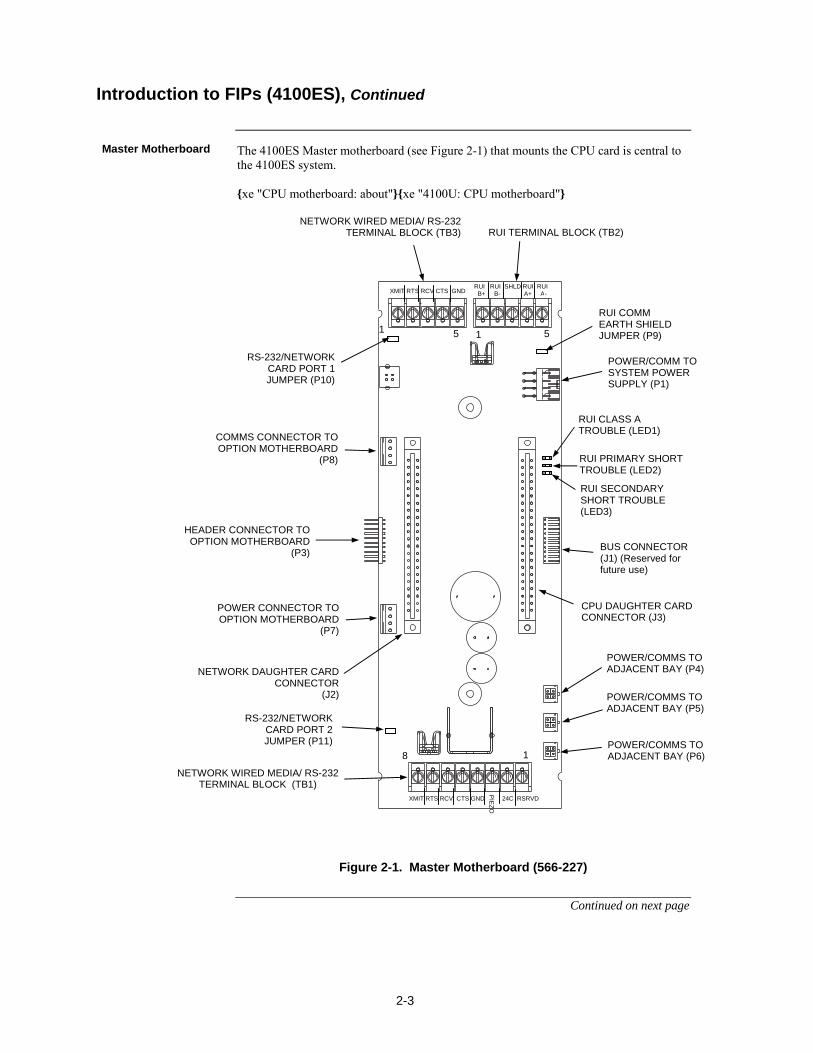
The 4100ES Master motherboard (see Figure 2-1) that mounts the CPU card is central to the 4100ES system. xe "CPU motherboard: about"xe "4100U: CPU motherboard"
Figure 2-1. Master Motherboard (566-227)
Continued on next page
Introduction to FIPs (4100ES), Continued
Master Motherboard
RUI TERMINAL BLOCK (TB2) NETWORK WIRED MEDIA/ RS-232
TERMINAL BLOCK (TB3)
POWER/COMM TO SYSTEM POWER SUPPLY (P1)
RUI CLASS A TROUBLE (LED1)
RUI PRIMARY SHORT TROUBLE (LED2)
RUI SECONDARY SHORT TROUBLE (LED3)
BUS CONNECTOR (J1) (Reserved for future use)
POWER/COMMS TO ADJACENT BAY (P4)
POWER/COMMS TO ADJACENT BAY (P5)
POWER/COMMS TO ADJACENT BAY (P6)
NETWORK WIRED MEDIA/ RS-232 TERMINAL BLOCK (TB1)
HEADER CONNECTOR TO OPTION MOTHERBOARD
(P3)
CPU DAUGHTER CARD CONNECTOR (J3)
POWER CONNECTOR TO OPTION MOTHERBOARD
(P7)
COMMS CONNECTOR TO OPTION MOTHERBOARD
(P8)
NETWORK DAUGHTER CARD CONNECTOR
(J2)
RUI COMM EARTH SHIELD JUMPER (P9)
RS-232/NETWORK CARD PORT 1 JUMPER (P10)
RS-232/NETWORK CARD PORT 2 JUMPER (P11)
XMIT RTS RCV CTS GND RUI RUI SHLD RUI RUI B+ B- A+ A-
1 1 5 5
XMIT RTS RCV CTS GND 24C RSRVD
PIE
ZO
1 8
2-4
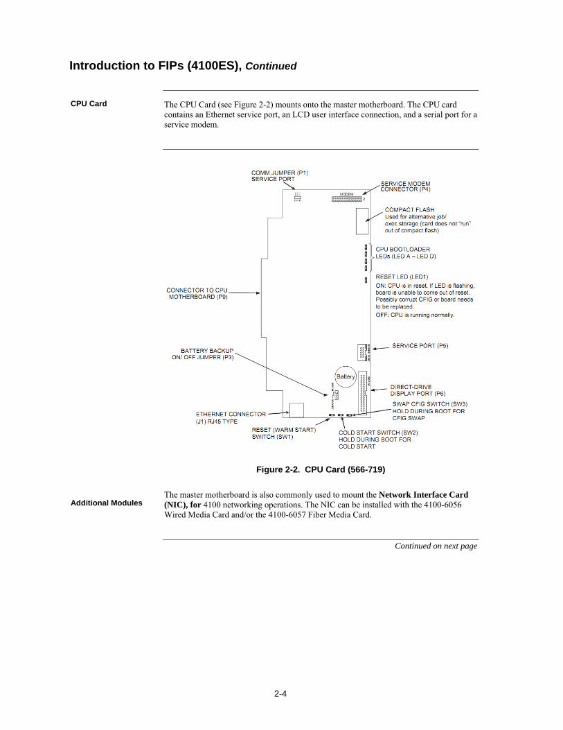
The CPU Card (see Figure 2-2) mounts onto the master motherboard. The CPU card contains an Ethernet service port, an LCD user interface connection, and a serial port for a service modem.
Figure 2-2. CPU Card (566-719)
The master motherboard is also commonly used to mount the Network Interface Card (NIC), for 4100 networking operations. The NIC can be installed with the 4100-6056 Wired Media Card and/or the 4100-6057 Fiber Media Card.
Continued on next page
Introduction to FIPs (4100ES), Continued
CPU Card
Additional Modules
2-5
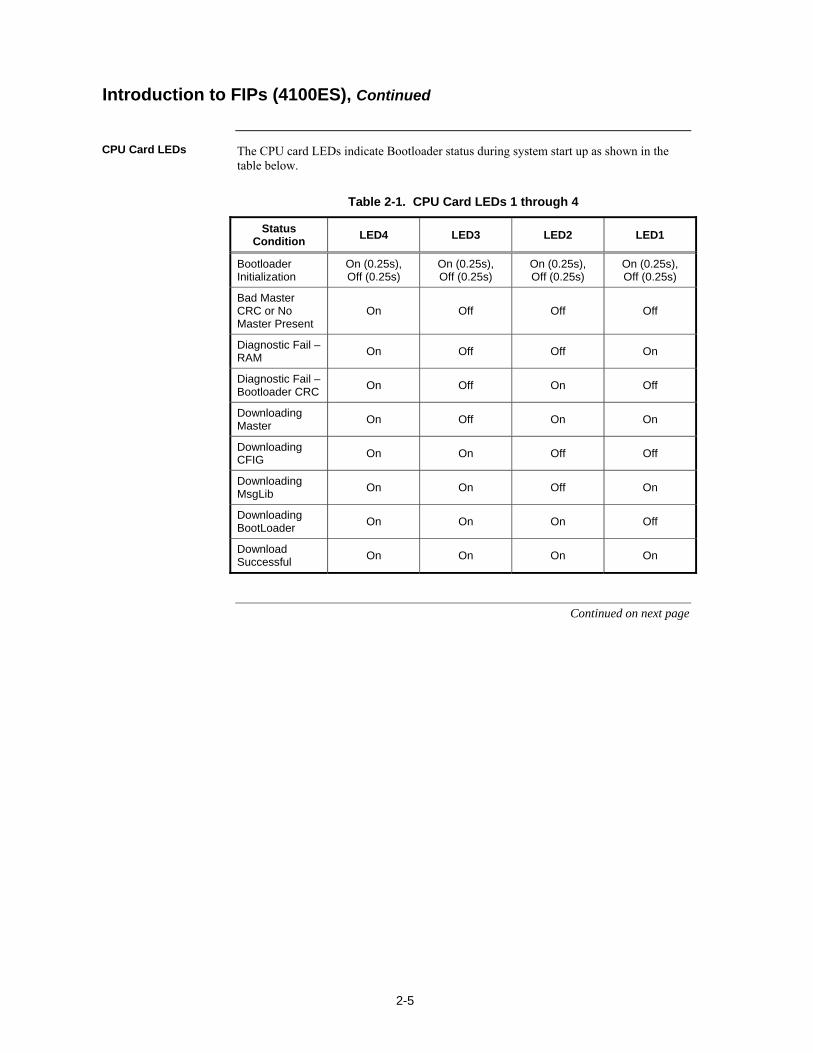
The CPU card LEDs indicate Bootloader status during system start up as shown in the table below.
Table 2-1. CPU Card LEDs 1 through 4
Status Condition
LED4 LED3 LED2 LED1
Bootloader Initialization
On (0.25s), Off (0.25s)
On (0.25s), Off (0.25s)
On (0.25s), Off (0.25s)
On (0.25s), Off (0.25s)
Bad Master CRC or No Master Present
On Off Off Off
Diagnostic Fail – RAM
On Off Off On
Diagnostic Fail – Bootloader CRC
On Off On Off
Downloading Master
On Off On On
Downloading CFIG
On On Off Off
Downloading MsgLib
On On Off On
Downloading BootLoader
On On On Off
Download Successful
On On On On
Continued on next page
Introduction to FIPs (4100ES), Continued
CPU Card LEDs
2-6
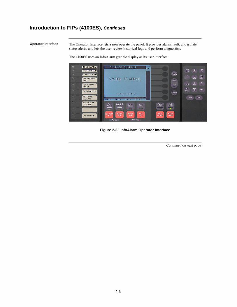
The Operator Interface lets a user operate the panel. It provides alarm, fault, and isolate status alerts, and lets the user review historical logs and perform diagnostics. The 4100ES uses an InfoAlarm graphic display as its user interface.
Figure 2-3. InfoAlarm Operator Interface
Continued on next page
Introduction to FIPs (4100ES), Continued
Operator Interface
2-7
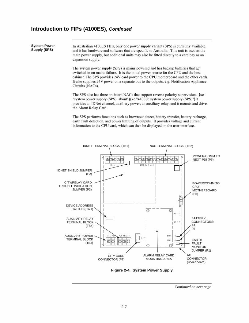
In Australian 4100ES FIPs, only one power supply variant (SPS) is currently available, and it has hardware and software that are specific to Australia. This unit is used as the main power supply, but additional units may also be fitted directly to a card bay as an expansion supply. The system power supply (SPS) is mains powered and has backup batteries that get switched in on mains failure. It is the initial power source for the CPU and the host cabinet. The SPS provides 24V card power to the CPU motherboard and the other cards. It also supplies 24V power on a separate bus to the outputs, e.g. Notification Appliance Circuits (NACs). The SPS also has three on-board NACs that support reverse polarity supervision. xe "system power supply (SPS): about"xe "4100U: system power supply (SPS)"It provides an IDNet channel, auxiliary power, an auxiliary relay, and it mounts and drives the Alarm Relay Card. The SPS performs functions such as brownout detect, battery transfer, battery recharge, earth fault detection, and power limiting of outputs. It provides voltage and current information to the CPU card, which can then be displayed on the user interface.
Figure 2-4. System Power Supply
Continued on next page
Introduction to FIPs (4100ES), Continued
System Power Supply (SPS)
ALARM RELAY CARD MOUNTING AREA
CITY CARD CONNECTOR (P7)
AUXILIARY RELAY TERMINAL BLOCK
(TB4)
AUXILIARY POWER TERMINAL BLOCK
(TB3)
AC CONNECTOR (under board)
BATTERY CONNECTORS: P4 P5
POWER/COMM TO CPU MOTHERBOARD (P8)
DEVICE ADDRESS SWITCH (SW1)
IDNET SHIELD JUMPER (P2)
CITY/RELAY CARD TROUBLE INDICATION
JUMPER (P3)
EARTH FAULT MONITOR JUMPER (P1)
NAC TERMINAL BLOCK (TB2) IDNET TERMINAL BLOCK (TB1)
POWER/COMM TO NEXT PDI (P6)
2-8
The FIP is powered by the SPS (System Power Supply) which gets its primary power from the AC mains and its secondary power from the backup batteries. The 24VDC bulk power on the SPS is unregulated, and is divided into three feeds, i.e. 24V Card, 24V Signal, and 24V Aux Power. 24V Card, which supplies the slave cards, and Aux power, which is accessible on screw terminals, are each rated at 2A and protected by a PTC. The 27.3V regulated battery charger is powered from the bulk supply and is switched off during alarm. The batteries only get connected to the bulk supply when the mains supply fails. The charger has two programmable options of rating, 1.4A for 6-18Ahr, and 3.3A for batteries above 18Ahr. The “heavy” 24V Signal feed is only accessible via the NACs on the SPS, or via a wire harness. xe "4100U: power connections"xe "system power: 4100U" IMPORTANT: AC power must be provided to the 4100ES from a dedicated
branch circuit.
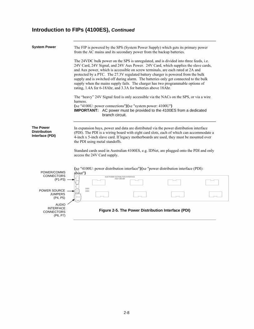
In expansion bays, power and data are distributed via the power distribution interface (PDI). The PDI is a wiring board with eight card slots, each of which can accommodate a 4-inch x 5-inch slave card. If legacy motherboards are used, they must be mounted over the PDI using metal standoffs. Standard cards used in Australian 4100ES, e.g. IDNet, are plugged onto the PDI and only access the 24V Card supply. xe "4100U: power distribution interface"xe "power distribution interface (PDI): about"
4100 POWER DISTRIBUTION INTERFACEASSY 566-084
Figure 2-5. The Power Distribution Interface (PDI)
Introduction to FIPs (4100ES), Continued
System Power
The Power Distribution Interface (PDI)
POWER/COMMS CONNECTORS
(P1-P3)
AUDIO INTERFACE
CONNECTORS (P6, P7)
POWER SOURCE JUMPERS
(P4, P5)

2-9
The important aspects of mounting the cabinet are: Access for the operator; Height of displays and controls; Free space for door opening; Cable entry for field wiring. Refer to AS 1670.1 for the height requirement and minimum access requirements for the cabinet. In general, 18U – 28U cabinets will need to be wall mounted. Mounting holes and cabinet dimensions are shown in drawing 1919-22. Door opening left/right should be specified with the order. The cabinets are symmetrical, top to bottom, so door opening can be swapped by removing the equipment, rotating the cabinet 180, then re-fitting the equipment.
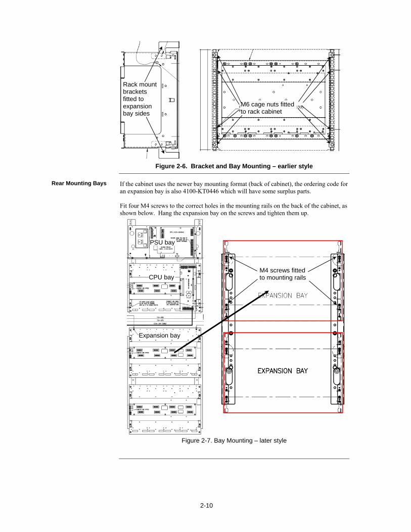
FIPs are ordered from the factory with bays and cards fitted as per the panel order spreadsheet. There are two formats used for bay mounting. In the earlier format, used with the 4U LCD user interface door, the bays are mounted to the front of the cabinet, with fold-down display doors fitted to the cabinets, and a 9U dress panel fastened in front of each bay. In the current format, used with the InfoAlarm graphic LCD user interface, the bays are mounted to the rear of the cabinet. The InfoAlarm and Zone LED displays are mounted on hinged doors mounted to the front of the cabinet. This allows the number of bays and number of display doors to be independently chosen, and allows better internal access for field wiring. Additional mounting bays may be ordered to fit to an existing cabinet.
If the cabinet uses the earlier bay mounting format, the ordering code for a new bay is 4100-KT0446 which includes the 19” rack mounting brackets and earth loom. Attach each mounting bracket to the two studs in the top and bottom of the front of each bayside plate as shown in Figure 2-6. Fit M6 cage nuts to the appropriate 19”rack holes, then attach the bay using M6 countersunk screws.
Step 1. Mounting Cabinets (4100ES)
Overview
Step 2. Mounting Card Bays to Cabinets (4100ES)
Overview
Front Mounting Bays
2-10
Figure 2-6. Bracket and Bay Mounting – earlier style
If the cabinet uses the newer bay mounting format (back of cabinet), the ordering code for an expansion bay is also 4100-KT0446 which will have some surplus parts. Fit four M4 screws to the correct holes in the mounting rails on the back of the cabinet, as shown below. Hang the expansion bay on the screws and tighten them up.
Figure 2-7. Bay Mounting – later style
Rear Mounting Bays
Rack mount brackets fitted to expansion bay sides
M6 cage nuts fitted to rack cabinet
M4 screws fitted to mounting rails
PSU bay
CPU bay
Expansion bay
2-11
xe "4100U: card configuration"
The CPU, SPS, and all other modules to be mounted in the FIP cabinets must be configured to operate correctly in the system via their DIP switch and jumper ports. This section describes the hardware configuration for the CPU and SPS, since they will always be used in the CPU bay.
The Master motherboard must be jumpered as follows: xe "card configuration: CPU"xe "CPU motherboard: configuring"
P9 determines whether the RUI SHIELD signal is connected to 24 C or Earth: Position 1 – 2: SHIELD to 24 C (default). Set to this position unless the system
uses a TrueAlert Power Supply (not listed for use in Australia). Position 2 – 3: SHIELD to Earth. Set to this position only if the system uses a
TrueAlert Power Supply.
Note: Some devices that connect to RUI have inherently grounded shield terminals, in which case 24 C cannot be used. If 24 C is used, a Negative Ground Fault will occur.
P10/P11: P10 is associated with Port 1 and P11 is associated with Port 2. P10 and P11 are used to set the CPU motherboard up to be attached to either a network card or a RS-232/2120 card: Position 1 – 2: Network card (NIC) fitted to CPU motherboard (default). Position 2 – 3: RS-232 card fitted to CPU motherboard.
The CPU card must be jumpered as follows: xe "card configuration: CPU (4100U)"xe "CPU motherboard: configuring"
P1 is used for engineering diagnostics (COMLAB): Position 1 – 2 : Download or no connection. Position 2 – 3 : Diagnostic mode.
P3 configures the RAM battery as ON or OFF: Position 1 – 2 : ON (use for normal operation). Position 2 – 3 : OFF.
The SPS must be configured as follows: xe "card configuration: SPS"xe "system power supply (SPS): configuring"
SW1: Using DIP switch SW1, set the SPS slave address. Use the address table in Appendix A.
P2: If the SPS IDNet outputs are being used, you may change P2 to configure the IDNet shield connection: Position 1 – 2 (bottom) : Connects the shield to 0 V (default). Position 2 – 3 (top) : Connects the shield to earth ground.
P3 configures relay 3 on the 4100-6033 Alarm Relay Card: Position 1 – 2 (top) : Removes fault monitoring on relay 3 (default). Position 2 – 3 (bottom) : Makes relay 3 activate when there is a fault. P1: Earth connect jumper: Position 1 – 2 (rhs): Enables Earth fault monitoring. Set to this position unless the
system uses a TrueAlert Power Supply under common 0V. Position 2 – 3 (lhs): Disables Earth fault monitoring. Set to this position only if the
system uses a TrueAlert Power Supply under common 0V.
Continued on next page
Step 3. Configuring Cards (4100ES)
Overview
Master Motherboard Configuration
CPU Card Configuration
SPS Configuration
2-12
P4/P5: The PDI backplane can be configured to draw its power from different sources via P4 and P5:xe "power distribution interface (PDI): configuring"xe "card configuration: power distribution interface (PDI)" To draw power from an XPS on the PDI, set jumpers on P4 and P5 to position 2
– 3. To draw power from P1 (from the previous bay), set jumpers on P4 and P5 to
position 1 – 2 (default). To remove power from the PDI, remove the jumper from P4.
Refer to the appropriate installation instructions to configure other cards that are located in CPU and expansion bays.
xe "4100U: card configuration"
Each card has to be interconnected with every other card in its bay. At the same time, bays in the FIP also have to be connected together. Read this section to ensure that cards and bays are interconnected.
Review the following guidelines before interconnecting modules and bays: The SPS provides 24V power to the CPU motherboard.
The CPU motherboard provides 8 V (3 A capacity) for use by Legacy 4100 slave cards. 24 V card power is routed through the motherboard for slave card use.
4100 internal comms and power are harnessed to other bays. Do not connect the 8 V at P7 to an 8 V converter on a Goldwing power supply or remote interface card.
24 V Card power from the SPS is rated at 2 A.
The 4-wire communications and power harness carries only the 24 V Card supply to a PDI, and not the 24V Signal supply.
Some of the wire harnesses supplied with cards are not required. These can be stored in case of future requirements.
Continued on next page
Step 3. Configuring Cards (4100ES), Continued
PDI Configuration
Configuring Other Cards
Step 4. Interconnecting Modules and Bays
Overview
Guidelines
2-13
Use the following directions to connect the CPU to the SPS and other motherboards: 1. Connect P3 on the SPS to P1 on the CPU motherboard using the 8 wire harness
733-998.
2. Make sure the 10 way right angle header, connector P3 on the master motherboard is secured to J1 on the next motherboard to the left. Repeat this for the third (leftmost) motherboard, and on if applicable.
xe "mounting: cards onto the PDI"The power distribution interface (PDI) mounted to the back of each expansion cabinet carries 24V Card power and data to each 4”x 5” card. Refer to “Step 5: Installing Modules into Expansion Bays (4100ES)” for instructions on mounting 4”x 5” cards to the PDI. Also bear in mind the following variations: In a Remote Transponder Unit (RTU), a transponder interface card (TIC) requires
additional interconnections. Refer to Chapter 3.
Regular motherboards require non-PDI interconnections to each other and to the CPU. Refer to “Step 5: Installing Modules into Expansion Bays (4100ES).”
The 4 wire harness 734-008 is used to carry 24V Card power and comms from bay to bay. Connector P1 on the PDI receives power from P3 on the previous PDI or from P6 on the SPS or from P7 or P8 on the CPU Motherboard. P2 on the PDI is used to carry power and comms to a 64/64 Controller. P3 is used to carry power and comms to the next PDI. Jumpers P4 and P5 on the PDI are normally set to positions 1-2 (left) to provide card power to the bay from P1 on the PDI. Set P4 and P5 to positions 2-3 (right) to provide card power to the bay only if an expansion SPS is fitted in that bay. Note: Interconnections can become more involved if 4100 motherboards are
used. Refer to “Step 5: Installing Modules into Expansion Bays (4100ES)” if this is the case.
Continued on next page
Step 4. Interconnecting Modules and Bays, Continued
Card Interconnections in the CPU Bay
Card Interconnections Within Expansion Bays
Basic Bay-To-Bay Interconnections
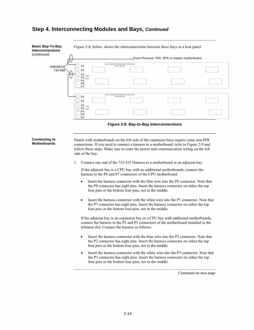
2-14
Figure 2-8, below, shows the interconnections between three bays in a host panel.
4100 POWER DISTRIBUTION INTERFACEASSY 566-084
4100 POWER DISTRIBUTION INTERFACEASSY 566-084
Figure 2-8. Bay-to-Bay Interconnections
Panels with motherboards on the left side of the expansion bays require some non-PDI connections. If you need to connect a harness to a motherboard, refer to Figure 2-9 and follow these steps. Make sure to route the power and communication wiring on the left side of the bay. 1. Connect one end of the 733-525 Harness to a motherboard in an adjacent bay.
If the adjacent bay is a CPU bay with no additional motherboards, connect the harness to the P8 and P7 connectors of the CPU motherboard:
Insert the harness connector with the blue wire into the P8 connector. Note that the P8 connector has eight pins. Insert the harness connector on either the top four pins or the bottom four pins, not in the middle.
Insert the harness connector with the white wire into the P7 connector. Note that the P7 connector has eight pins. Insert the harness connector on either the top four pins or the bottom four pins, not in the middle.
If the adjacent bay is an expansion bay or a CPU bay with additional motherboards, connect the harness to the P2 and P3 connectors of the motherboard installed in the leftmost slot. Connect the harness as follows:
Insert the harness connector with the blue wire into the P2 connector. Note that the P2 connector has eight pins. Insert the harness connector on either the top four pins or the bottom four pins, not in the middle.
Insert the harness connector with the white wire into the P3 connector. Note that the P3 connector has eight pins. Insert the harness connector on either the top four pins or the bottom four pins, not in the middle.
Continued on next page
Step 4. Interconnecting Modules and Bays, Continued
Basic Bay-To-Bay Interconnections (continued)
Connecting to Motherboards
HARNESS 734-008
From Previous PDI, SPS or master motherboard
P1
P2
P3 P4 P5 P6 P7
P1
P2
P3 P4 P5 P6 P7
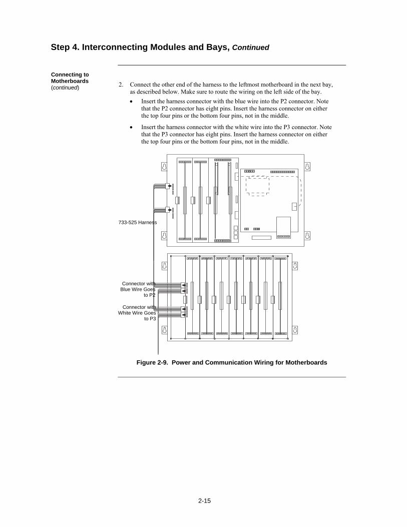
2-15
2. Connect the other end of the harness to the leftmost motherboard in the next bay, as described below. Make sure to route the wiring on the left side of the bay.
Insert the harness connector with the blue wire into the P2 connector. Note that the P2 connector has eight pins. Insert the harness connector on either the top four pins or the bottom four pins, not in the middle.
Insert the harness connector with the white wire into the P3 connector. Note that the P3 connector has eight pins. Insert the harness connector on either the top four pins or the bottom four pins, not in the middle.
Figure 2-9. Power and Communication Wiring for Motherboards
Step 4. Interconnecting Modules and Bays, Continued
Connecting to Motherboards (continued)
Connector with Blue Wire Goes
to P2
Connector with White Wire Goes
to P3
733-525 Harness
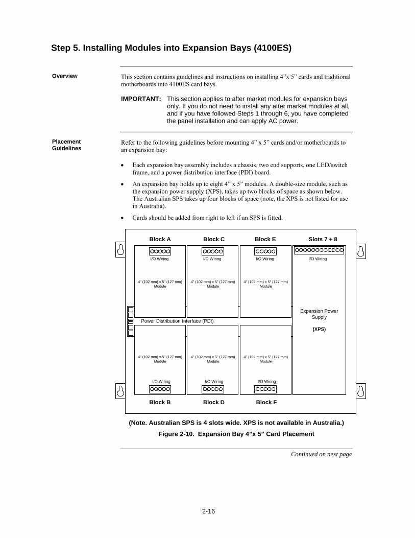
2-16
This section contains guidelines and instructions on installing 4”x 5” cards and traditional motherboards into 4100ES card bays. IMPORTANT: This section applies to after market modules for expansion bays
only. If you do not need to install any after market modules at all, and if you have followed Steps 1 through 6, you have completed the panel installation and can apply AC power.
Refer to the following guidelines before mounting 4” x 5” cards and/or motherboards to an expansion bay: Each expansion bay assembly includes a chassis, two end supports, one LED/switch
frame, and a power distribution interface (PDI) board.
An expansion bay holds up to eight 4” x 5” modules. A double-size module, such as the expansion power supply (XPS), takes up two blocks of space as shown below. The Australian SPS takes up four blocks of space (note, the XPS is not listed for use in Australia).
Cards should be added from right to left if an SPS is fitted.
Power Distribution Interface (PDI)
Expansion PowerSupply
(XPS)
I/O Wiring I/O Wiring I/O Wiring
I/O Wiring I/O Wiring I/O Wiring
I/O Wiring
Block A Block C
Block B Block D
Block E Slots 7 + 8
Block F
4" (102 mm) x 5" (127 mm)Module
4" (102 mm) x 5" (127 mm)Module
4" (102 mm) x 5" (127 mm)Module
4" (102 mm) x 5" (127 mm)Module
4" (102 mm) x 5" (127 mm)Module
4" (102 mm) x 5" (127 mm)Module
(Note. Australian SPS is 4 slots wide. XPS is not available in Australia.)
Figure 2-10. Expansion Bay 4”x 5” Card Placement
Continued on next page
Step 5. Installing Modules into Expansion Bays (4100ES)
Overview
Placement Guidelines
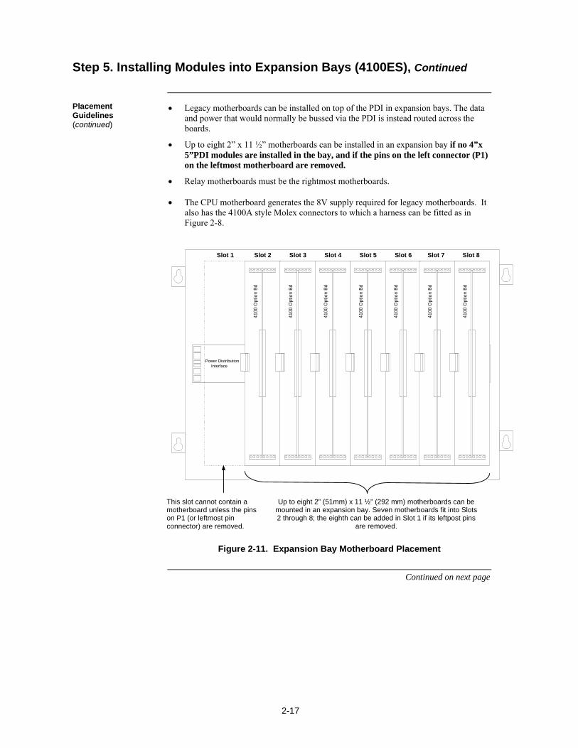
2-17
Legacy motherboards can be installed on top of the PDI in expansion bays. The data and power that would normally be bussed via the PDI is instead routed across the boards.
Up to eight 2” x 11 ½” motherboards can be installed in an expansion bay if no 4”x 5”PDI modules are installed in the bay, and if the pins on the left connector (P1) on the leftmost motherboard are removed.
Relay motherboards must be the rightmost motherboards.
The CPU motherboard generates the 8V supply required for legacy motherboards. It also has the 4100A style Molex connectors to which a harness can be fitted as in Figure 2-8.
Power Distribution Interface
4100
Opt
ion
Bd
4100
Opt
ion
Bd
4100
Opt
ion
Bd
4100
Opt
ion
Bd
4100
Opt
ion
Bd
4100
Opt
ion
Bd
4100
Opt
ion
Bd
Slot 2 Slot 3 Slot 4 Slot 5 Slot 6 Slot 7 Slot 8Slot 1
This SlotMust
RemainEmpty
Figure 2-11. Expansion Bay Motherboard Placement
Continued on next page
Step 5. Installing Modules into Expansion Bays (4100ES), Continued
Placement Guidelines (continued)
This slot cannot contain a motherboard unless the pins on P1 (or leftmost pin connector) are removed.
Up to eight 2” (51mm) x 11 ½” (292 mm) motherboards can be mounted in an expansion bay. Seven motherboards fit into Slots 2 through 8; the eighth can be added in Slot 1 if its leftpost pins
are removed.
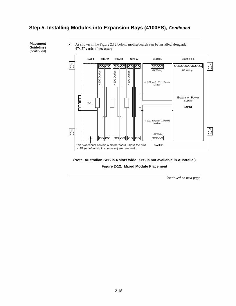
2-18
As shown in the Figure 2.12 below, motherboards can be installed alongside 4”x 5” cards, if necessary.
No BoardsAllowed
inThis Slot
PDI
Expansion PowerSupply
(XPS)
I/O Wiring
I/O Wiring
I/O Wiring
410
0 O
ptio
n
410
0 O
ptio
n
410
0 O
ptio
n
Slot 1 Slot 2 Slot 3 Slot 4Position
5
Position6
Position7 & 8
Block E Slots 7 + 8
Block FThis slot cannot contain a motherboard unless the pins on P1 (or leftmost pin connector) are removed.
4" (102 mm) x 5" (127 mm)Module
4" (102 mm) x 5" (127 mm)Module
(Note. Australian SPS is 4 slots wide. XPS is not available in Australia.)
Figure 2-12. Mixed Module Placement
Continued on next page
Step 5. Installing Modules into Expansion Bays (4100ES), Continued
Placement Guidelines (continued)
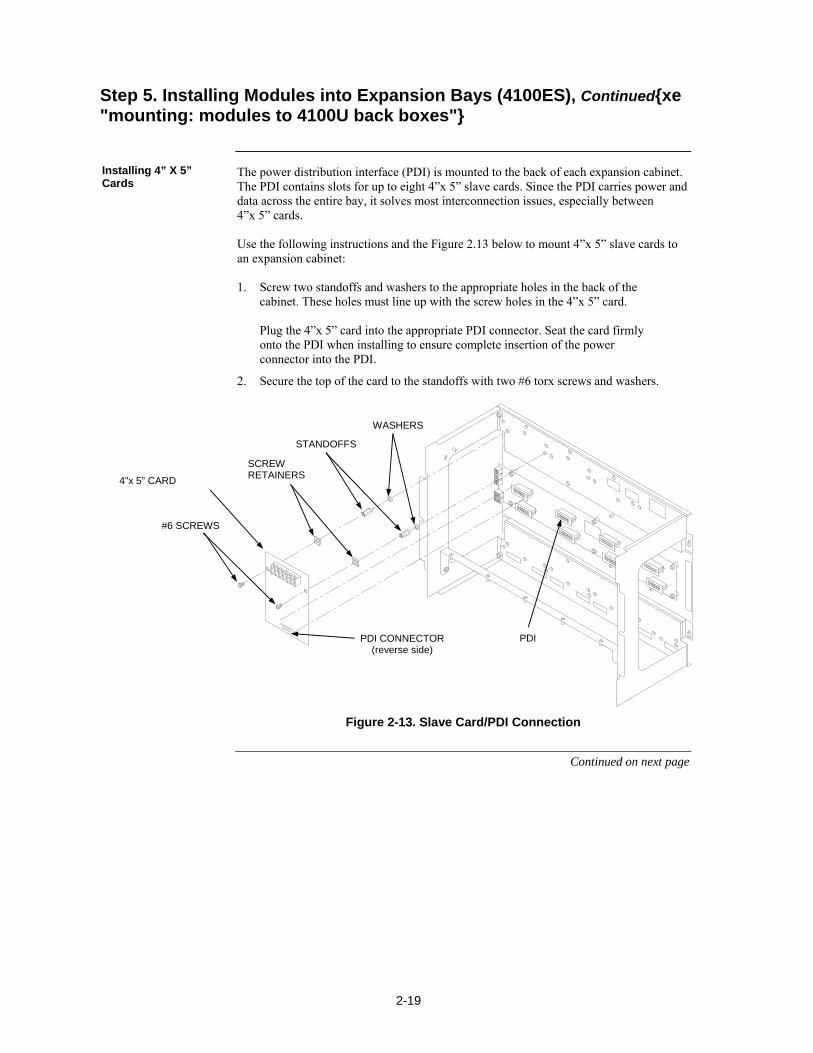
2-19
The power distribution interface (PDI) is mounted to the back of each expansion cabinet. The PDI contains slots for up to eight 4”x 5” slave cards. Since the PDI carries power and data across the entire bay, it solves most interconnection issues, especially between 4”x 5” cards. Use the following instructions and the Figure 2.13 below to mount 4”x 5” slave cards to an expansion cabinet: 1. Screw two standoffs and washers to the appropriate holes in the back of the
cabinet. These holes must line up with the screw holes in the 4”x 5” card. Plug the 4”x 5” card into the appropriate PDI connector. Seat the card firmly onto the PDI when installing to ensure complete insertion of the power connector into the PDI.
2. Secure the top of the card to the standoffs with two #6 torx screws and washers.
Figure 2-13. Slave Card/PDI Connection
Continued on next page
Step 5. Installing Modules into Expansion Bays (4100ES), Continuedxe "mounting: modules to 4100U back boxes"
Installing 4” X 5” Cards
4”x 5” CARD
STANDOFFS
#6 SCREWS
WASHERS
PDI CONNECTOR (reverse side)
PDI
SCREW RETAINERS
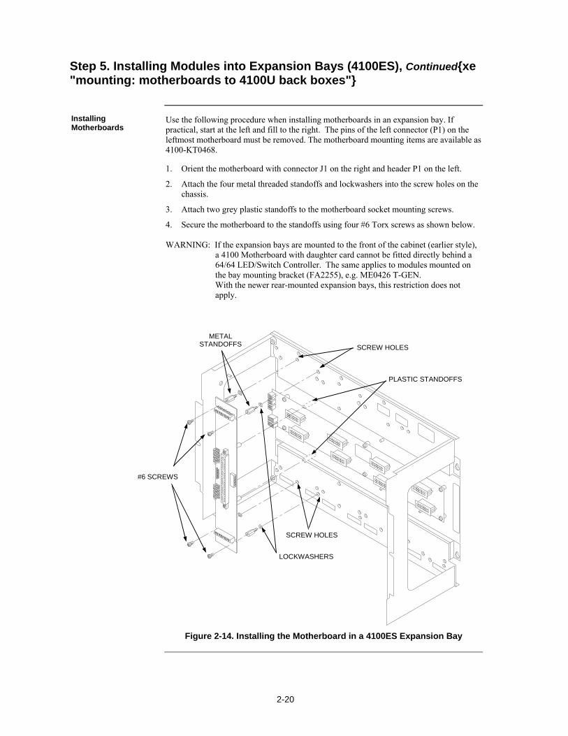
2-20
Use the following procedure when installing motherboards in an expansion bay. If practical, start at the left and fill to the right. The pins of the left connector (P1) on the leftmost motherboard must be removed. The motherboard mounting items are available as 4100-KT0468.
1. Orient the motherboard with connector J1 on the right and header P1 on the left.
2. Attach the four metal threaded standoffs and lockwashers into the screw holes on the chassis.
3. Attach two grey plastic standoffs to the motherboard socket mounting screws.
4. Secure the motherboard to the standoffs using four #6 Torx screws as shown below. WARNING: If the expansion bays are mounted to the front of the cabinet (earlier style),
a 4100 Motherboard with daughter card cannot be fitted directly behind a 64/64 LED/Switch Controller. The same applies to modules mounted on the bay mounting bracket (FA2255), e.g. ME0426 T-GEN. With the newer rear-mounted expansion bays, this restriction does not apply.
Figure 2-14. Installing the Motherboard in a 4100ES Expansion Bay
Step 5. Installing Modules into Expansion Bays (4100ES), Continuedxe "mounting: motherboards to 4100U back boxes"
Installing Motherboards
#6 SCREWS
LOCKWASHERS
METAL STANDOFFS SCREW HOLES
SCREW HOLES
PLASTIC STANDOFFS
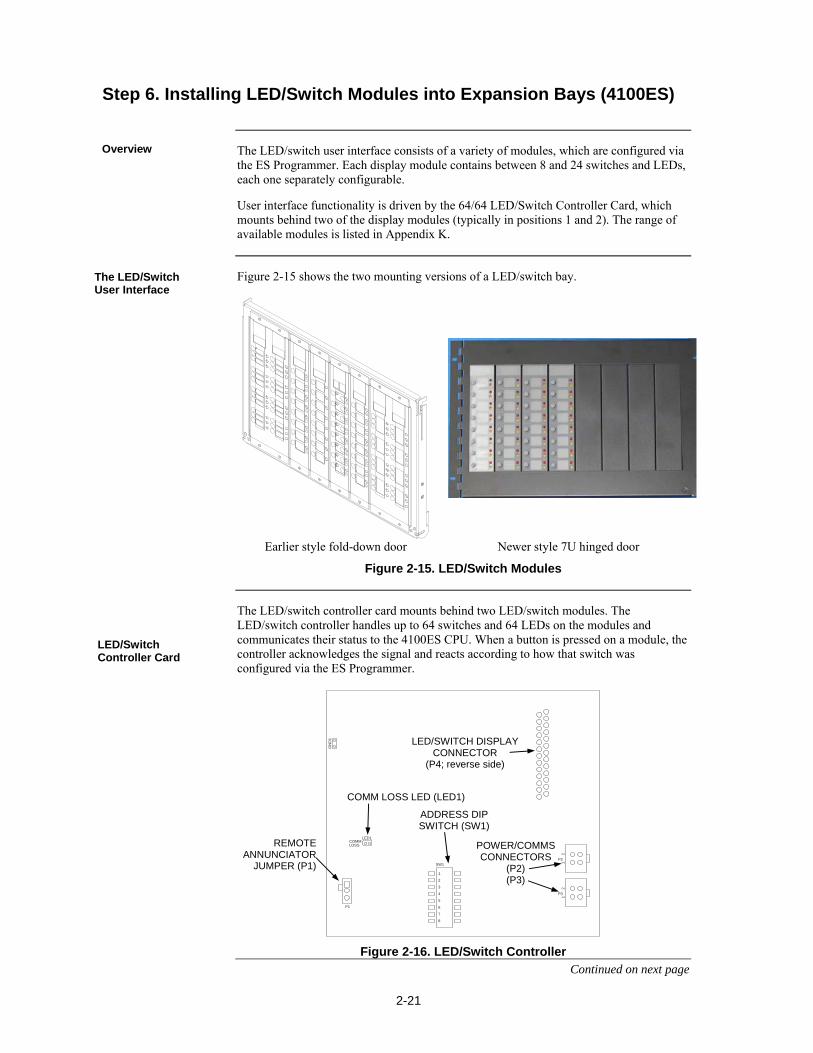
2-21
The LED/switch user interface consists of a variety of modules, which are configured via the ES Programmer. Each display module contains between 8 and 24 switches and LEDs, each one separately configurable.
User interface functionality is driven by the 64/64 LED/Switch Controller Card, which mounts behind two of the display modules (typically in positions 1 and 2). The range of available modules is listed in Appendix K.
Figure 2-15 shows the two mounting versions of a LED/switch bay.
Earlier style fold-down door Newer style 7U hinged door
Figure 2-15. LED/Switch Modules
The LED/switch controller card mounts behind two LED/switch modules. The LED/switch controller handles up to 64 switches and 64 LEDs on the modules and communicates their status to the 4100ES CPU. When a button is pressed on a module, the controller acknowledges the signal and reacts according to how that switch was configured via the ES Programmer.
GN
D1
LED1
P2
12
SW1
1
2
3
4
5
6
7
8
P1
COMMLOSS
P3
12
Figure 2-16. LED/Switch Controller Continued on next page
Step 6. Installing LED/Switch Modules into Expansion Bays (4100ES)
Overview
The LED/Switch User Interface
LED/Switch Controller Card
LED/SWITCH DISPLAY CONNECTOR
(P4; reverse side)
POWER/COMMS CONNECTORS
(P2) (P3)
COMM LOSS LED (LED1)
ADDRESS DIP SWITCH (SW1)
REMOTE ANNUNCIATOR
JUMPER (P1)
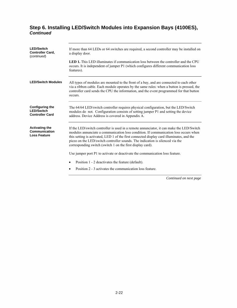
2-22
If more than 64 LEDs or 64 switches are required, a second controller may be installed on a display door. LED 1. This LED illuminates if communication loss between the controller and the CPU occurs. It is independent of jumper P1 (which configures different communication loss features).
All types of modules are mounted to the front of a bay, and are connected to each other via a ribbon cable. Each module operates by the same rules: when a button is pressed, the controller card sends the CPU the information, and the event programmed for that button occurs.
The 64/64 LED/switch controller requires physical configuration, but the LED/Switch modules do not. Configuration consists of setting jumper P1 and setting the device address. Device Address is covered in Appendix A.
If the LED/switch controller is used in a remote annunciator, it can make the LED/Switch modules annunciate a communication loss condition. If communication loss occurs when this setting is activated, LED 1 of the first connected display card illuminates, and the piezo on the LED/switch controller sounds. The indication is silenced via the corresponding switch (switch 1 on the first display card). Use jumper port P1 to activate or deactivate the communication loss feature. Position 1 - 2 deactivates the feature (default).
Position 2 - 3 activates the communication loss feature.
Continued on next page
Step 6. Installing LED/Switch Modules into Expansion Bays (4100ES), Continued
LED/Switch Controller Card, (continued)
LED/Switch Modules
Configuring the LED/Switch Controller Card
Activating the Communication Loss Feature
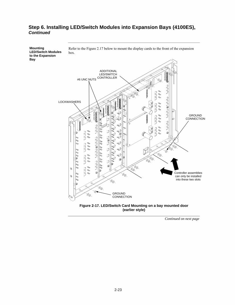
2-23
Refer to the Figure 2.17 below to mount the display cards to the front of the expansion box.
Figure 2-17. LED/Switch Card Mounting on a bay mounted door (earlier style)
Continued on next page
Step 6. Installing LED/Switch Modules into Expansion Bays (4100ES), Continued
Mounting LED/Switch Modules to the Expansion Bay
#6 UNC NUTS
GROUND CONNECTION
ADDITIONAL LED/SWITCH
CONTROLLER
GROUND CONNECTION
LOCKWASHERS
Controller assemblies can only be installed into these two slots
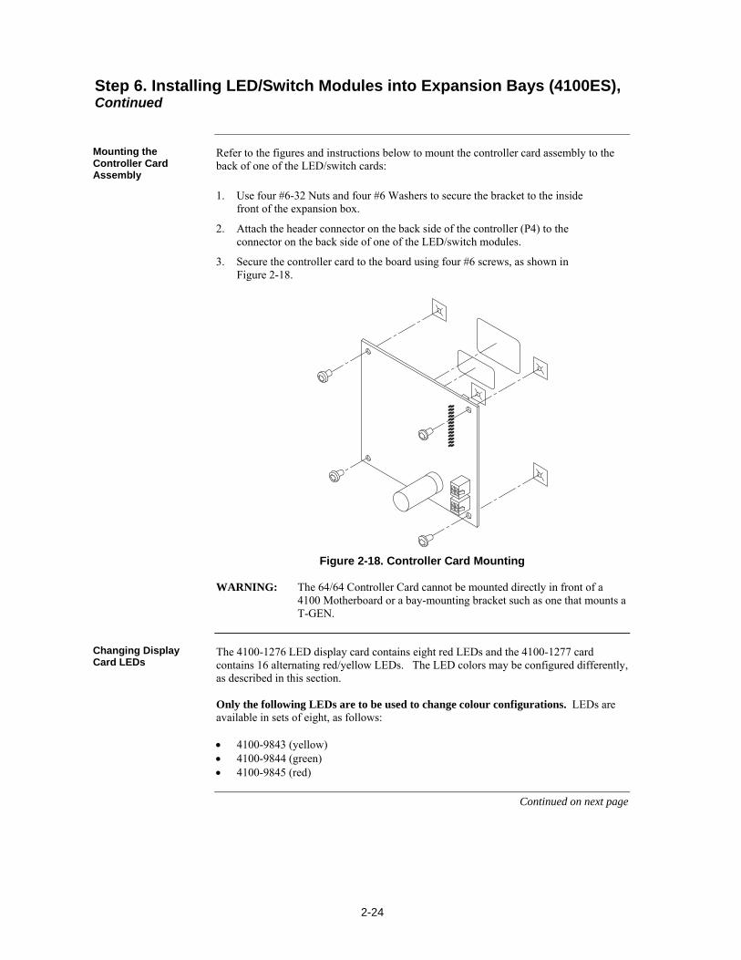
2-24
Refer to the figures and instructions below to mount the controller card assembly to the back of one of the LED/switch cards:
1. Use four #6-32 Nuts and four #6 Washers to secure the bracket to the inside front of the expansion box.
2. Attach the header connector on the back side of the controller (P4) to the connector on the back side of one of the LED/switch modules.
3. Secure the controller card to the board using four #6 screws, as shown in Figure 2-18.
Figure 2-18. Controller Card Mounting WARNING: The 64/64 Controller Card cannot be mounted directly in front of a 4100 Motherboard or a bay-mounting bracket such as one that mounts a T-GEN.
The 4100-1276 LED display card contains eight red LEDs and the 4100-1277 card contains 16 alternating red/yellow LEDs. The LED colors may be configured differently, as described in this section. Only the following LEDs are to be used to change colour configurations. LEDs are available in sets of eight, as follows: 4100-9843 (yellow) 4100-9844 (green) 4100-9845 (red)
Continued on next page
Step 6. Installing LED/Switch Modules into Expansion Bays (4100ES), Continued
Mounting the Controller Card Assembly
Changing Display Card LEDs
2-25
Figure 2-19. Assembling / Disassembling the LED Display Card (pluggable LED version, only)
User interface wiring consists of connecting the LED/switch controller card to the expansion bay’s power distribution interface (PDI), and connecting display cards to each other. This section describes both procedures.
Continued on next page
Step 6. Installing LED/Switch Modules into Expansion Bays (4100ES), Continued
Changing Display Card LEDs, (continued)
Interconnecting Cards
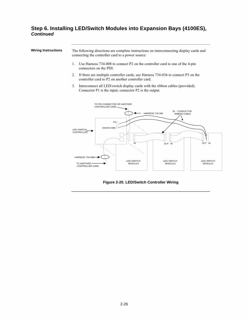
2-26
The following directions are complete instructions on interconnecting display cards and connecting the controller card to a power source: 1. Use Harness 734-008 to connect P2 on the controller card to one of the 4-pin
connectors on the PDI.
2. If there are multiple controller cards, use Harness 734-036 to connect P3 on the controller card to P2 on another controller card.
3. Interconnect all LED/switch display cards with the ribbon cables (provided). Connector P1 is the input; connector P2 is the output.
TO PDI CONNECTOR OR ANOTHER CONTROLLER CARD
P4
(reverse side)
HARNESS 734- 036
LED/ SWITCHCONTROLLER
26 - CONDUCTORRIBBON CABLE
LED/ SWITCHMODULE 3
LED/ SWITCHMODULE 2
LED/ SWITCHMODULE 1TO ANOTHER
CONTROLLER CARD
HARNESS 734 008
IN OUT IN OUT IN
Figure 2-20. LED/Switch Controller Wiring
Step 6. Installing LED/Switch Modules into Expansion Bays (4100ES), Continued
Wiring Instructions
3-1
MINIPLEX transponder interface cards (TICs) allow for data and power interconnections between the 4100ES host panel and remote locations. This chapter describes the transponder installation for 4100ES MINIPLEX/RTU systems. xe "MINIPLEX 4100 Fire Alarm System: transponder interface card (TIC)"xe "transponder interface card (TIC)"
Refer to the page number listed in this table for information on a specific topic.
Topic See Page #
Introduction to MINIPLEX Transponders (4100ES) 3-2
MINIPLEX System Guidelines (4100ES) 3-4
Configuring Cards (4100ES) 3-5
TIC/Riser Mounting (4100ES) 3-6
TIC/Motherboard Interconnections (4100ES) 3-7
RUI Wiring (4100ES) 3-8
Chapter 3 Installing 4100ES MINIPLEX/RTU Components
Introduction
In this Chapter

3-2
The 4100ES MINIPLEX/RTU system is comprised of a host panel containing everything required in a standalone cabinet (see Chapter 1), plus: One or more remote MINIPLEX transponder cabinets.
A transponder interface card (TIC) in each transponder cabinet.
RUI Communication wiring from the RUI module in the host panel can be extended to a transponder interface card (TIC) in a remote transponder unit (RTU). The transponder cabinet has at least one TIC module in it.
Australian 4100ES uses the Basic Transponder Interface Card (TIC) Module. Other versions of TIC are not listed for use in Australia. Transponder Interface Cards (TICs) transfer data from the 4100ES CPU to the slave cards in the RTU. The Basic TIC is an addressable slave card that contains RUI outputs, an audio riser output, a user interface output, and a power and comms output for connecting to legacy motherboards.
xe "transponder interface card (TIC): illustrations"xe "audio riser card"
Figure 3-1. Transponder Interface Cards
Introduction to MINIPLEX Transponders (4100ES)
Overview
Transponder Cabinets
Transponder Interface Cards (TICs)
Basic TIC
4100-0620 BASIC TIC

3-3
The Basic TIC has the following LED indicators: LED1. indicates communication loss with the CPU.
LED2. Indicates when an RUI ground fault search is active.
LED4. Indicates an RUI Style 7 primary trouble.
LED5. Indicates an RUI Style 7 secondary trouble. xe "transponder interface card (TIC): specifications"
Table 4-1 lists the specifications for the TIC.
Table 3-1. TIC Specifications
Electrical Specifications
Input Voltage 18-33 VDC
Output Voltage 8 V @ 1 A; 100 mV p-p ripple
Input Current 87 mA, excluding the 8V load from legacy slave cards powered by theTIC.
Environmental Specifications
Operating Temperature 32 to 120 F (0 to 49 C)
Humidity 10% to 93% relative humidity at 90 F (32 C)
Introduction to MINIPLEX Transponders (4100ES), Continued
Card Specifications

3-4
The rules on this page apply exclusively to MINIPLEX systems. Review each guideline before installing a MINIPLEX 4100ES system.
All wiring is between 0.75mm2 (minimum) and 2.5mm2 (maximum).
All wiring is supervised and power-limited.
All wiring that leaves the building requires overvoltage protection. Install the protection module inside an electrical box wherever the wiring enters or leaves the building. A maximum of four 2081-9044 protection modules may be connected to one RUI channel. The 2081-9044 is rated for 200mA (maximum).
AS 1670 allows no more than 40 detectors/addressable devices to be lost by a single fault. This is particularly relevant for Class B (spur) configurations.
For Class B (spur) operation: - The maximum direct cable distance from the host panel to any transponder is 760m. - “T” spurs are allowed. - The sum of all the cable lengths (including all “T” spurs) must be less than 3,000m. - Maximum allowed line-to-line capacitance (“+” to “-” terminals) is 0.58 uF. For applications with shielded wire, be sure that the total capacitance from line to line plus the shield to either line is no more than 0.58 uF (this is usually only a problem when using MIMS cables).
For Class A (loop) operation, the maximum cable distance around the loop is 760m. “T” spurs are not allowed.
Annunciators and transponder interface cards support loop operation when the system is wired Class A.
The master control panel must be a 4100ES Fire Alarm Control Panel.
Up to 4 RUI cards in the 4100ES Control Panel can be used for distributing transponder wiring in different directions or for supporting different wiring requirements (such as using a Style 7 (Class A) RUI for serial annunciators).
Up to a total of 31 transponders can be controlled from the 4100ES Control Panel, and can be distributed as required among the RUI cards.
MINIPLEX System Guidelines (4100ES)
Overview
Guidelines
3-5
The TIC and all other cards mounted in the transponder cabinet and attached expansion bays must be configured to operate correctly in the system via their DIP switch and jumper ports. The CPU motherboard may have to be configured as well.
P9 on the CPU motherboard determines whether the RUI SHIELD signal is connected to 24 C or Earth. Position 1 – 2: SHIELD to 24 C (default). Position 2 – 3: SHIELD to Earth. Note: Some devices that connect to RUI have inherently grounded shield
terminals, in which case 24 C cannot be used. If 24 C is used, a Negative Ground Fault will occur.
The TIC must be assigned a device address via DIP switch SW1. Refer to Appendix A for the address switch table.
Refer to the respective installation sheets to configure the other cards that are located in the transponder cabinet and attached expansion bays.
Configuring Cards (4100ES)xe "transponder interface card (TIC): configuring"xe "card configuration: transponder interface card (TIC)"
Overview
CPU Motherboard DIP Switch
TIC Configuration
Configuring Other Cards
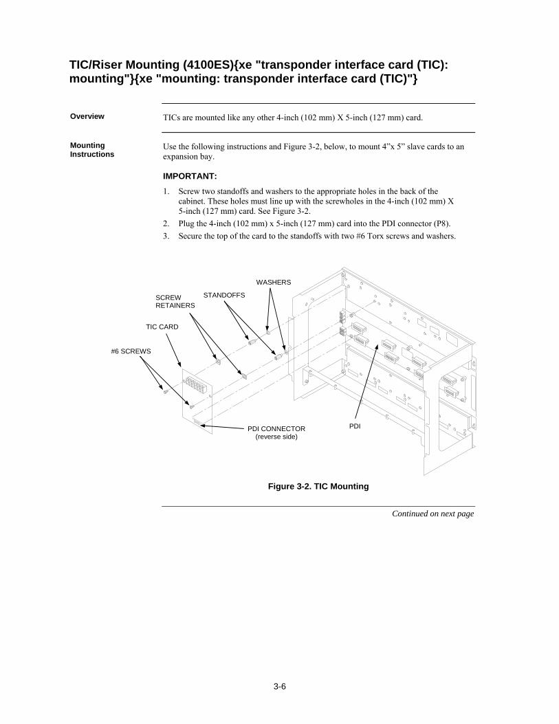
3-6
TICs are mounted like any other 4-inch (102 mm) X 5-inch (127 mm) card.
Use the following instructions and Figure 3-2, below, to mount 4”x 5” slave cards to an expansion bay. IMPORTANT:
1. Screw two standoffs and washers to the appropriate holes in the back of the cabinet. These holes must line up with the screwholes in the 4-inch (102 mm) X 5-inch (127 mm) card. See Figure 3-2.
2. Plug the 4-inch (102 mm) x 5-inch (127 mm) card into the PDI connector (P8).
3. Secure the top of the card to the standoffs with two #6 Torx screws and washers.
Figure 3-2. TIC Mounting
Continued on next page
TIC/Riser Mounting (4100ES)xe "transponder interface card (TIC): mounting"xe "mounting: transponder interface card (TIC)"
Overview
Mounting Instructions
TIC CARD
STANDOFFS
#6 SCREWS
WASHERS
PDI CONNECTOR (reverse side)
PDI
SCREW RETAINERS
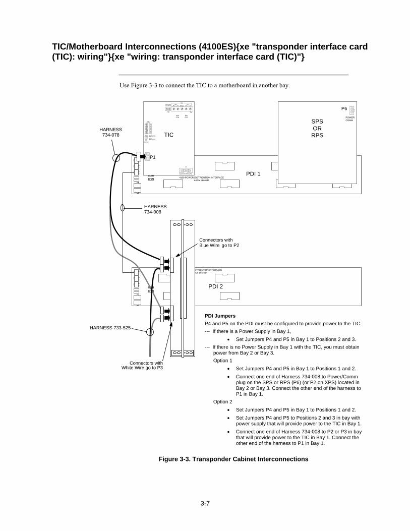
3-7
4100 POWER DISTRIBUTION INTERFACEASSY 566-084
4100 POWER DISTRIBUTION INTERFACEASSY 566-084
LED4
SW1
LED1
TB2
PRI
LED2
P1
P3
LED5
TB3
SECRUI
TMPR SW24C INPUT SHLD
4100COMMLOSSRUIG.F.
SEARCH
AUDIO RISER CARD
HARNESS734-008
TI
SPSOR
RPSC
PDI 1
PDI 2
HARNESS734-078
P1
P6
POWER/COMM
Connectors withWhite Wire go to P3
HARNESS 733-525
Connectors withBlue Wire go to P2
Use Figure 3-3 to connect the TIC to a motherboard in another bay.
Figure 3-3. Transponder Cabinet Interconnections
TIC/Motherboard Interconnections (4100ES)xe "transponder interface card (TIC): wiring"xe "wiring: transponder interface card (TIC)"
PDI Jumpers
P4 and P5 on the PDI must be configured to provide power to the TIC.
--- If there is a Power Supply in Bay 1,
Set Jumpers P4 and P5 in Bay 1 to Positions 2 and 3.
--- If there is no Power Supply in Bay 1 with the TIC, you must obtain power from Bay 2 or Bay 3.
Option 1
Set Jumpers P4 and P5 in Bay 1 to Positions 1 and 2.
Connect one end of Harness 734-008 to Power/Comm plug on the SPS or RPS (P6) (or P2 on XPS) located in Bay 2 or Bay 3. Connect the other end of the harness to P1 in Bay 1.
Option 2
Set Jumpers P4 and P5 in Bay 1 to Positions 1 and 2.
Set Jumpers P4 and P5 to Positions 2 and 3 in bay with power supply that will provide power to the TIC in Bay 1.
Connect one end of Harness 734-008 to P2 or P3 in bay that will provide power to the TIC in Bay 1. Connect the other end of the harness to P1 in Bay 1.
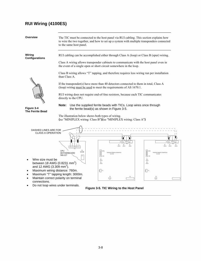
3-8
The TIC must be connected to the host panel via RUI cabling. This section explains how to wire the two together, and how to set up a system with multiple transponders connected to the same host panel.
RUI cabling can be accomplished either through Class A (loop) or Class B (spur) wiring. Class A wiring allows transponder cabinets to communicate with the host panel even in the event of a single open or short circuit somewhere in the loop. Class B wiring allows “T” tapping, and therefore requires less wiring run per installation than Class A. If the transponder(s) have more than 40 detectors connected to them in total, Class A (loop) wiring must be used to meet the requirements of AS 1670.1. RUI wiring does not require end-of-line resistors, because each TIC communicates directly to the CPU. Note: Use the supplied ferrite beads with TICs. Loop wires once through
the ferrite bead(s) as shown in Figure 3-5. The illustration below shows both types of wiring. xe "MINIPLEX wiring: Class B"xe "MINIPLEX wiring: Class A"
TRANSPONDER INTERFACEASSY 566-094
MSB
LSB
LED1
AD
DR
ES
S
LED3
PRI
B+ B- SHLD A+ A-
SECRUI
SHLD
LED4 LED5
LED2
P1
P2 P3
RUI
P9
P1
1 2 3TRANSPONDER INTERFACEASSY 566-094
MSB
LSB
LED1
AD
DR
ES
SLED3
PRI SECRUI
SHLD
LED4 LED5
LED2
P1
P2
Figure 3-5. TIC Wiring to the Host Panel
RUI Wiring (4100ES)
Overview
Wiring Configurations
Figure 3-4 The Ferrite Bead
DASHED LINES ARE FOR CLASS A OPERATION
Wire size must be between 18 AWG (0.8231 mm2) and 12 AWG (3.309 mm2).
Maximum wiring distance: 760m. Maximum “T” tapping length: 3000m. Maintain correct polarity on terminal
connections. Do not loop wires under terminals.
CPU MOTHERBOARD 566-227
4-1
xe "Network 4100 Fire Alarm System"
A standalone or MINIPLEX 4100 system becomes a network node when a 4100 Network Interface Card (NIC) or other compatible network card is installed and connected to another network node. How network cards connect to each other depends on the type of media network cards being used.
Refer to the page number listed in this table for information on a specific topic.
Topic See Page #
Getting Started 4-2
Introduction to the 4100 Network Interface Card (NIC) 4-2
Step 1. Configuring Network Cards 4-5
Step 2. Mounting Media Cards to the NIC 4-7
Step 3. Mounting Network Cards 4-8
Step 4. Wiring Network Cards 4-9
Chapter 4 Networking
Introduction
In this Chapter
4-2
This chapter describes how to turn a standalone or MINIPLEX FIP into a network node. This process consists of the following: Step 1. Configuring cards for operation (using DIP switches and jumper ports).
Step 2. Mounting media cards to the network interface card (NIC).
Step 3. Mounting network cards.
Step 4. Wiring network cards. Each step is described in this chapter. Before beginning the installation, review the next few pages for a detailed description of network cards and the media cards that mount onto them.
The Network Interface Card (NIC) is a slave card that uses the internal 4100 serial bus to communicate with the master. The NIC connects FIPs in a network, allowing for communication between each panel via optical fibre, modem, or twisted shielded pair wire. The NICs are designed to be connected in a ring arrangement, so that one circuit fault does not cause the entire system to fail. The ring arrangement provides the most secure and fault-tolerant wiring possible. Two types of media boards of either type can be used with the NIC card: The Fiber-Optic Media Card can be used for electrically noisy environments or
for connecting externally to other buildings.
The Wired Media Card is used in all other types of applications.
Up to two media boards of either type can be plugged into each NIC. The same NIC can use a combination of two types of media boards (for example, a NIC may have a wired media card connected to port 1 and a fibreoptic media card connected to port 2). Note: other types of network interfaces are available for special functions, such as single mode fibre modems and TCP/IP bridge cards. Please contact your Simplex representative for more details about these.
Continued on next page
Getting Started
Overview
Introduction to the 4100 Network Interface Card (NIC)
Overview
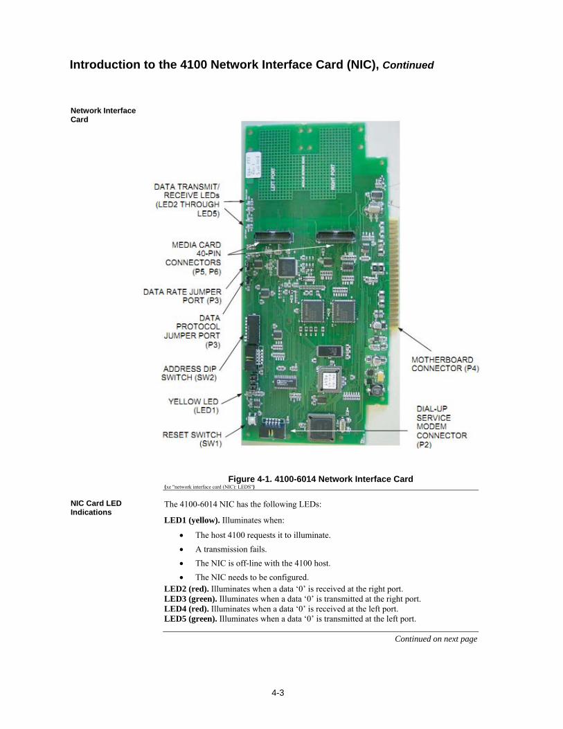
4-3
Figure 4-1. 4100-6014 Network Interface Card xe "network interface card (NIC): LEDS"
The 4100-6014 NIC has the following LEDs:
LED1 (yellow). Illuminates when:
The host 4100 requests it to illuminate.
A transmission fails.
The NIC is off-line with the 4100 host.
The NIC needs to be configured. LED2 (red). Illuminates when a data ‘0’ is received at the right port. LED3 (green). Illuminates when a data ‘0’ is transmitted at the right port. LED4 (red). Illuminates when a data ‘0’ is received at the left port. LED5 (green). Illuminates when a data ‘0’ is transmitted at the left port.
Continued on next page
Introduction to the 4100 Network Interface Card (NIC), Continued
Network Interface Card
NIC Card LED Indications
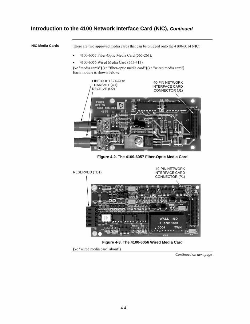
4-4
There are two approved media cards that can be plugged onto the 4100-6014 NIC: 4100-6057 Fiber-Optic Media Card (565-261).
4100-6056 Wired Media Card (565-413).
xe "media cards"xe "fiber-optic media card"xe "wired media card" Each module is shown below.
Figure 4-2. The 4100-6057 Fiber-Optic Media Card
RESERVED (TB1)
Figure 4-3. The 4100-6056 Wired Media Card
xe "wired media card: about"
Continued on next page
Introduction to the 4100 Network Interface Card (NIC), Continued
NIC Media Cards
40-PIN NETWORK INTERFACE CARD CONNECTOR (J1)
FIBER-OPTIC DATA: TRANSMIT (U1), RECEIVE (U2)
40-PIN NETWORK INTERFACE CARD CONNECTOR (P1)
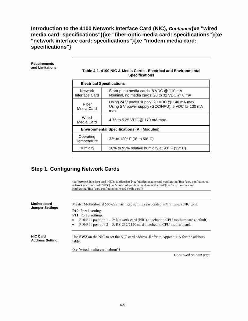
4-5
Table 4-1. 4100 NIC & Media Cards - Electrical and Environmental Specifications
Electrical Specifications
Network Interface Card
Startup, no media cards: 8 VDC @ 110 mA Nominal, no media cards: 20 to 32 VDC @ 0 mA
Fiber Media Card
Using 24 V power supply: 20 VDC @ 140 mA max. Using 5 V power supply (GCC/NPU): 5 VDC @ 130 mA max.
Wired Media Card
4.75 to 5.25 VDC @ 170 mA max.
Environmental Specifications (All Modules)
Operating Temperature 32 to 120 F (0 to 50 C)
Humidity 10% to 93% relative humidity at 90 F (32 C)
xe "network interface card (NIC): configuring"xe "modem media card: configuring"xe "card configuration: network interface card (NIC)"xe "card configuration: modem media card"xe "wired media card: configuring"xe "card configuration: wired media card"
Master Motherboard 566-227 has these settings associated with fitting a NIC to it:
P10: Port 1 settings. P11: Port 2 settings. P10/P11 position 1 – 2: Network card (NIC) attached to CPU motherboard (default). P10/P11 position 2 – 3: RS-232/2120 card attached to CPU motherboard.
Use SW2 on the NIC to set the NIC card address. Refer to Appendix A for the address table. xe "wired media card: about"
Continued on next page
Introduction to the 4100 Network Interface Card (NIC), Continuedxe "wired media card: specifications"xe "fiber-optic media card: specifications"xe "network interface card: specifications"xe "modem media card: specifications"
Requirements and Limitations
Step 1. Configuring Network Cards
Motherboard Jumper Settings
NIC Card Address Setting
4-6
There are two shunt jumper ports on the NIC card that need to be set: P3 and P4.
P3: Determines the NIC data transmission rate, 57.6 kbits/second or 9600 bits/second. Position 1 – 2 (the right two pins) or no pins jumpered: 57.6 kbits/second. Position 2 – 3 (the left two pins): 9600 bits/second.
P4: Determines the data protocol, 8-bit or 9-bit, that the NIC card is using. Position 1 – 2 (the right two pins) or no pins jumpered: 9-bit. Position 2 – 3 (the left two pins): 8-bit.
All settings are labelled on the card.
P2: Tells the system which wire type is to be used. Positions 1 – 2, 5 – 6, and 7 – 8: 18 AWG shielded, twisted pair wiring. Remove all jumpers to specify 24 AWG twisted pair telephone cable wiring.
IMPORTANT: When using the wired media card, the Earth fault detection is performed on the left port only. Remove R1 (1 Ohm resistor) from the media card on the right port.
Step 1. Configuring Network Cards, Continued
NIC Card Jumper Settings
Wired Media Card Jumper Settings
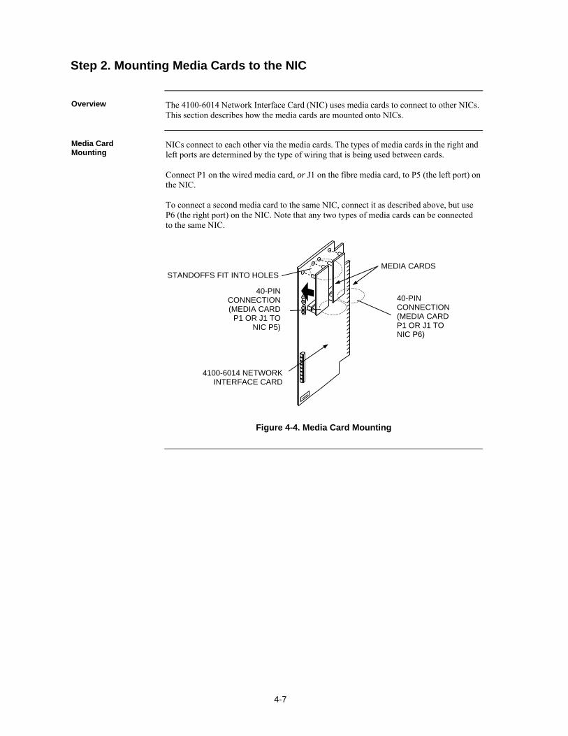
4-7
The 4100-6014 Network Interface Card (NIC) uses media cards to connect to other NICs. This section describes how the media cards are mounted onto NICs.
NICs connect to each other via the media cards. The types of media cards in the right and left ports are determined by the type of wiring that is being used between cards. Connect P1 on the wired media card, or J1 on the fibre media card, to P5 (the left port) on the NIC. To connect a second media card to the same NIC, connect it as described above, but use P6 (the right port) on the NIC. Note that any two types of media cards can be connected to the same NIC.
Figure 4-4. Media Card Mounting
Step 2. Mounting Media Cards to the NIC
Overview
Media Card Mounting
MEDIA CARDS
4100-6014 NETWORK INTERFACE CARD
40-PIN CONNECTION (MEDIA CARD
P1 OR J1 TO NIC P5)
40-PIN CONNECTION (MEDIA CARD P1 OR J1 TO NIC P6)
STANDOFFS FIT INTO HOLES
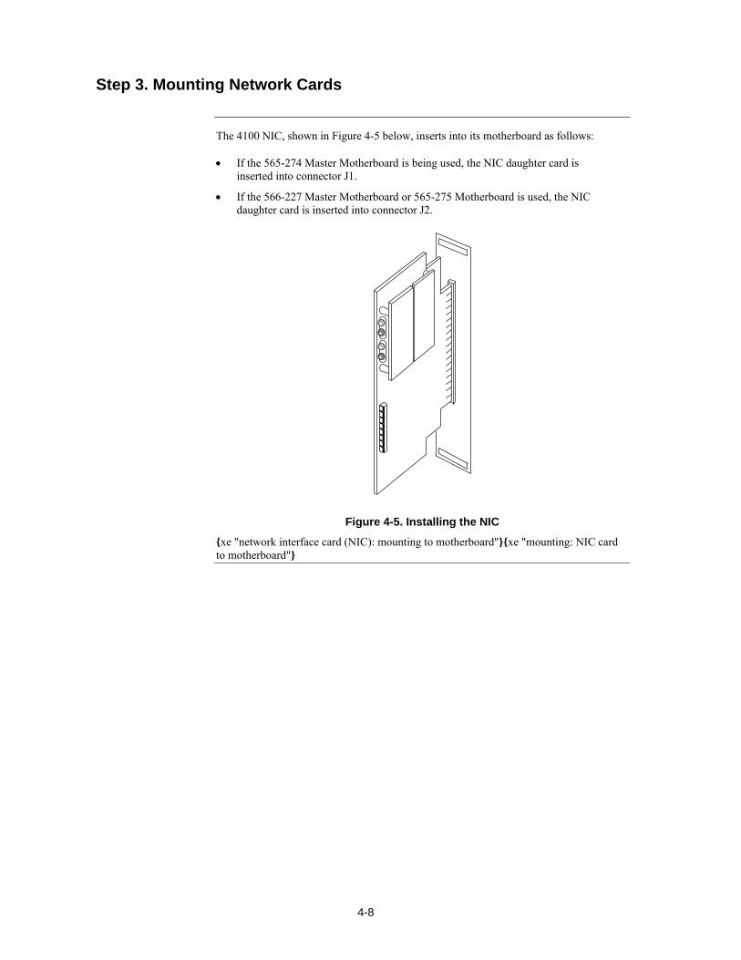
4-8
The 4100 NIC, shown in Figure 4-5 below, inserts into its motherboard as follows: If the 565-274 Master Motherboard is being used, the NIC daughter card is
inserted into connector J1.
If the 566-227 Master Motherboard or 565-275 Motherboard is used, the NIC daughter card is inserted into connector J2.
Figure 4-5. Installing the NIC
xe "network interface card (NIC): mounting to motherboard"xe "mounting: NIC card to motherboard"
Step 3. Mounting Network Cards

4-9
The nodes in the network now have to be wired together, so that the NIC in one host panel connects to the NIC in the next panel. This section contains guidelines and instructions for NIC wiring. xe "network interface card (NIC): wiring"xe "wiring: network interface card (NIC)"
Refer to the following guidelines whenever field wiring the NICs:
Network nodes must be wired right to left port, regardless of the media type selected.
Style 7 protection is achieved by wiring the nodes in a loop. A single fault (except an Earth fault) will cause the network to reconfigure for degraded Style 7 (Style 4) operation. A second fault (except an Earth fault) will result in the network dividing into two separate networks.
Style 4 is achieved by wiring the nodes in a linear fashion. Style 4 networks are not fault-tolerant and a single fault (except an Earth fault) will result in the network dividing into two separate networks.
Earth fault detection is performed on the left port only. When a network Earth fault occurs, the trouble is only reported on the node whose left port is connected to the link with the earth fault.
All 18 AWG (0.8231 mm2) wiring used with 4100-6056 Wired Media Cards must be twisted-shielded pair. All 24 AWG (0.2047 mm2) (telephone cable) used with 4100-6056 must be twisted pair. When shielded cable is used, the shield must be terminated to chassis Earth on the left port only.
It is permissible to use mixed media in a network. For example, some spans may be “wired media” while others are optical fibre.
Each NIC has a jumper for selecting between network data rates of 57.6kbps and 9.6kbps. All cards in the network must be set for the same rate. (When physical bridging is used, the data rate must be set for 9.6kbps).
Each NIC has a jumper for selecting between 8- and 9-bit network protocols. All cards in the network must be set for the same network protocol. (When physical bridging is used, the protocol must be set for 8-bit).
All network wiring except the shield is supervised and power limited.
When wiring leaves the building, 2081-9044 Overvoltage Protectors are required. One overvoltage protector is installed where wiring leaves the building; another is installed where wiring enters the next building.
Continued on next page
Step 4. Wiring Network Cards
Overview
Wiring Guidelines
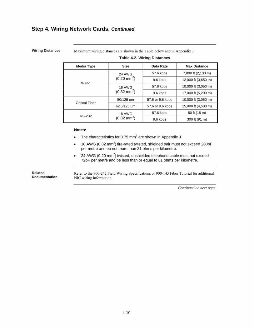
4-10
Maximum wiring distances are shown in the Table below and in Appendix J.
Table 4-2. Wiring Distances
Media Type Size Data Rate Max Distance
Wired
24 AWG (0.20 mm2)
57.6 kbps 7,000 ft (2,130 m)
9.6 kbps 12,000 ft (3,650 m)
18 AWG (0.82 mm2)
57.6 kbps 10,000 ft (3,050 m)
9.6 kbps 17,000 ft (5,200 m)
Optical Fiber 50/125 um 57.6 or 9.6 kbps 10,000 ft (3,050 m)
62.5/125 um 57.6 or 9.6 kbps 15,000 ft (4,500 m)
RS-232 18 AWG
(0.82 mm2)
57.6 kbps 50 ft (15 m)
9.6 kbps 300 ft (91 m)
Notes:
The characteristics for 0.75 mm2 are shown in Appendix J.
18 AWG (0.82 mm2) fire-rated twisted, shielded pair must not exceed 200pF per metre and be not more than 21 ohms per kilometre.
24 AWG (0.20 mm2) twisted, unshielded telephone cable must not exceed 72pF per metre and be less than or equal to 81 ohms per kilometre.
Refer to the 900-242 Field Wiring Specifications or 900-143 Fiber Tutorial for additional NIC wiring information.
Continued on next page
Step 4. Wiring Network Cards, Continued
Wiring Distances
Related Documentation
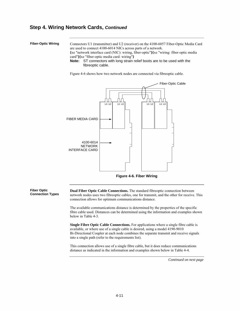
4-11
Connectors U1 (transmitter) and U2 (receiver) on the 4100-6057 Fiber-Optic Media Card are used to connect 4100-6014 NICs across parts of a network. xe "network interface card (NIC): wiring, fiber-optic"xe "wiring: fiber-optic media card"xe "fiber-optic media card: wiring" Note: ST connectors with long strain relief boots are to be used with the
fibreoptic cable. Figure 4-6 shows how two network nodes are connected via fibreoptic cable.
U1 U2 U1 U2 U1 U2 U1 U2
Figure 4-6. Fiber Wiring
Dual Fiber Optic Cable Connections. The standard fibreoptic connection between network nodes uses two fibreoptic cables, one for transmit, and the other for receive. This connection allows for optimum communications distance. The available communications distance is determined by the properties of the specific fibre cable used. Distances can be determined using the information and examples shown below in Table 4-3. Single Fibre Optic Cable Connections. For applications where a single fibre cable is available, or where use of a single cable is desired, using a model 4190-9010 Bi-Directional Coupler at each node combines the separate transmit and receive signals into a single path (refer to the requirements list). This connection allows use of a single fibre cable, but it does reduce communications distance as indicated in the information and examples shown below in Table 4-4.
Continued on next page
Step 4. Wiring Network Cards, Continued
Fiber-Optic Wiring
Fiber Optic Connection Types
FIBER MEDIA CARD
4100-6014 NETWORK
INTERFACE CARD
Fiber-Optic Cable
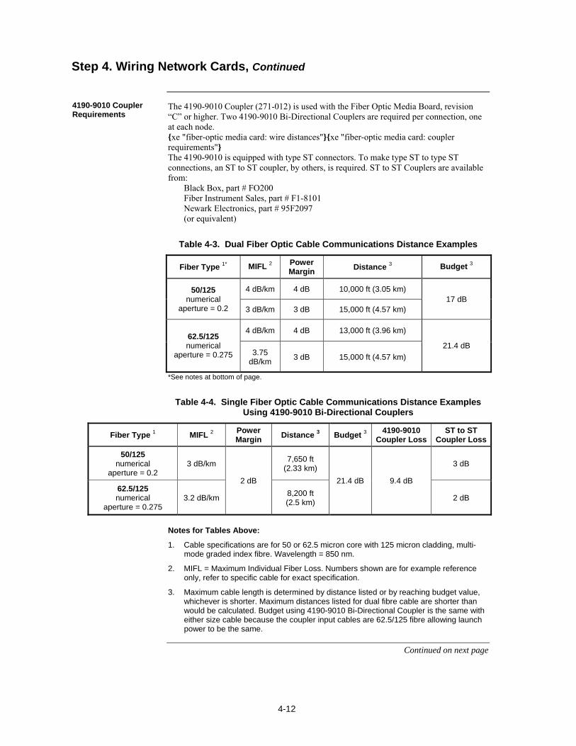
4-12
The 4190-9010 Coupler (271-012) is used with the Fiber Optic Media Board, revision “C” or higher. Two 4190-9010 Bi-Directional Couplers are required per connection, one at each node. xe "fiber-optic media card: wire distances"xe "fiber-optic media card: coupler requirements" The 4190-9010 is equipped with type ST connectors. To make type ST to type ST connections, an ST to ST coupler, by others, is required. ST to ST Couplers are available from: Black Box, part # FO200 Fiber Instrument Sales, part # F1-8101 Newark Electronics, part # 95F2097 (or equivalent)
Table 4-3. Dual Fiber Optic Cable Communications Distance Examples
Fiber Type 1* MIFL 2 Power Margin
Distance 3 Budget 3
50/125 numerical
aperture = 0.2
4 dB/km 4 dB 10,000 ft (3.05 km) 17 dB
3 dB/km 3 dB 15,000 ft (4.57 km)
62.5/125 numerical
aperture = 0.275
4 dB/km 4 dB 13,000 ft (3.96 km)
21.4 dB 3.75
dB/km 3 dB 15,000 ft (4.57 km)
*See notes at bottom of page.
Table 4-4. Single Fiber Optic Cable Communications Distance Examples Using 4190-9010 Bi-Directional Couplers
Fiber Type 1 MIFL 2 Power Margin
Distance 3 Budget 3 4190-9010
Coupler Loss ST to ST
Coupler Loss
50/125 numerical
aperture = 0.2 3 dB/km
2 dB
7,650 ft (2.33 km)
21.4 dB 9.4 dB
3 dB
62.5/125 numerical
aperture = 0.275 3.2 dB/km
8,200 ft (2.5 km)
2 dB
Notes for Tables Above:
1. Cable specifications are for 50 or 62.5 micron core with 125 micron cladding, multi-mode graded index fibre. Wavelength = 850 nm.
2. MIFL = Maximum Individual Fiber Loss. Numbers shown are for example reference only, refer to specific cable for exact specification.
3. Maximum cable length is determined by distance listed or by reaching budget value, whichever is shorter. Maximum distances listed for dual fibre cable are shorter than would be calculated. Budget using 4190-9010 Bi-Directional Coupler is the same with either size cable because the coupler input cables are 62.5/125 fibre allowing launch power to be the same.
Continued on next page
Step 4. Wiring Network Cards, Continued
4190-9010 Coupler Requirements
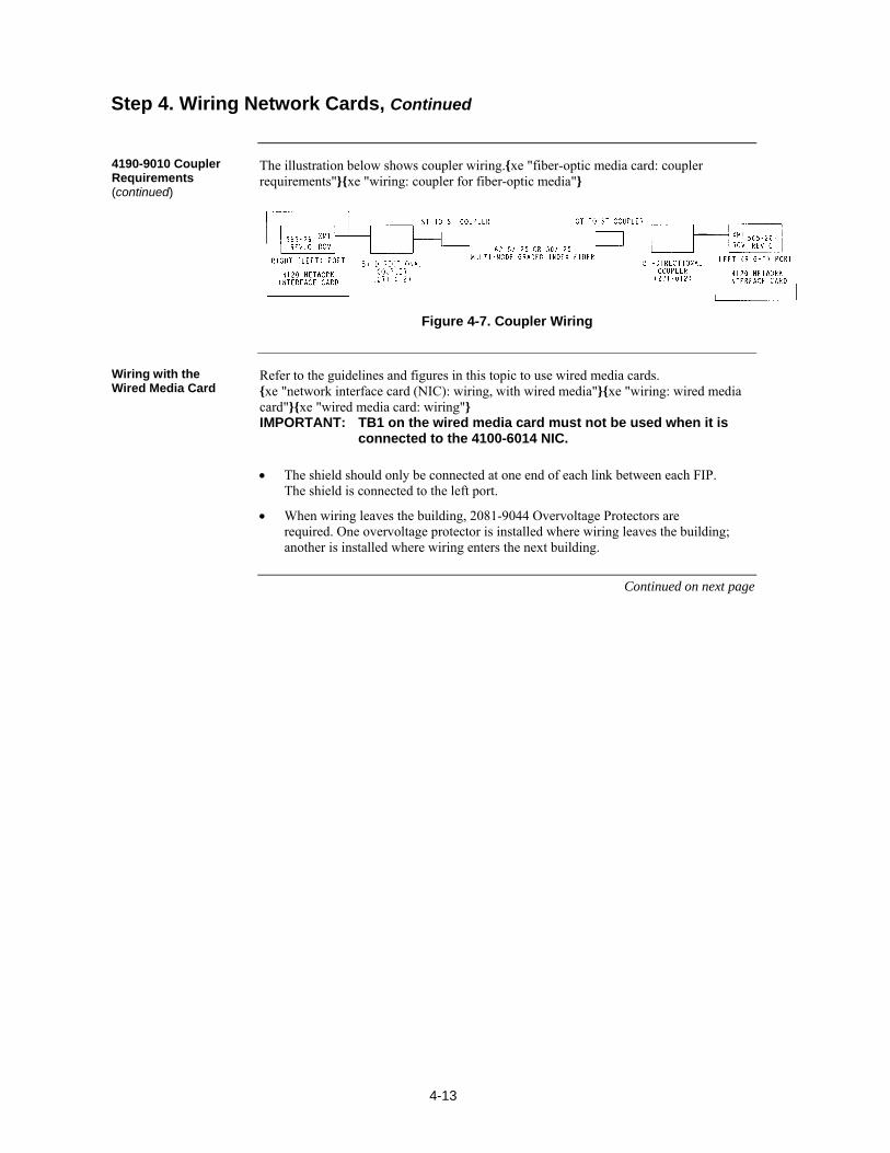
4-13
The illustration below shows coupler wiring.xe "fiber-optic media card: coupler requirements"xe "wiring: coupler for fiber-optic media"
Figure 4-7. Coupler Wiring
Refer to the guidelines and figures in this topic to use wired media cards. xe "network interface card (NIC): wiring, with wired media"xe "wiring: wired media card"xe "wired media card: wiring" IMPORTANT: TB1 on the wired media card must not be used when it is
connected to the 4100-6014 NIC.
The shield should only be connected at one end of each link between each FIP. The shield is connected to the left port.
When wiring leaves the building, 2081-9044 Overvoltage Protectors are required. One overvoltage protector is installed where wiring leaves the building; another is installed where wiring enters the next building.
Continued on next page
Step 4. Wiring Network Cards, Continued
4190-9010 Coupler Requirements (continued)
Wiring with the Wired Media Card
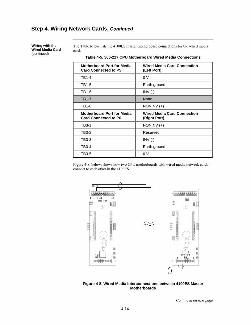
4-14
The Table below lists the 4100ES master motherboard connections for the wired media card.
Table 4-5. 566-227 CPU Motherboard Wired Media Connections
Motherboard Port for Media Card Connected to P5
Wired Media Card Connection (Left Port)
TB1-4 0 V
TB1-5 Earth ground
TB1-6 INV (-)
TB1-7 None
TB1-8 NONINV (+)
Motherboard Port for Media Card Connected to P6
Wired Media Card Connection (Right Port)
TB3-1 NONINV (+)
TB3-2 Reserved
TB3-3 INV (-)
TB3-4 Earth ground
TB3-5 0 V
Figure 4-8, below, shows how two CPU motherboards with wired media network cards connect to each other in the 4100ES.
Figure 4-8. Wired Media Interconnections between 4100ES Master Motherboards
Continued on next page
Step 4. Wiring Network Cards, Continued
Wiring with the Wired Media Card (continued)
18 AWG 1 TB3 10
Right Port
R+ R-
Left Port 8 TB1 1
L+ L-
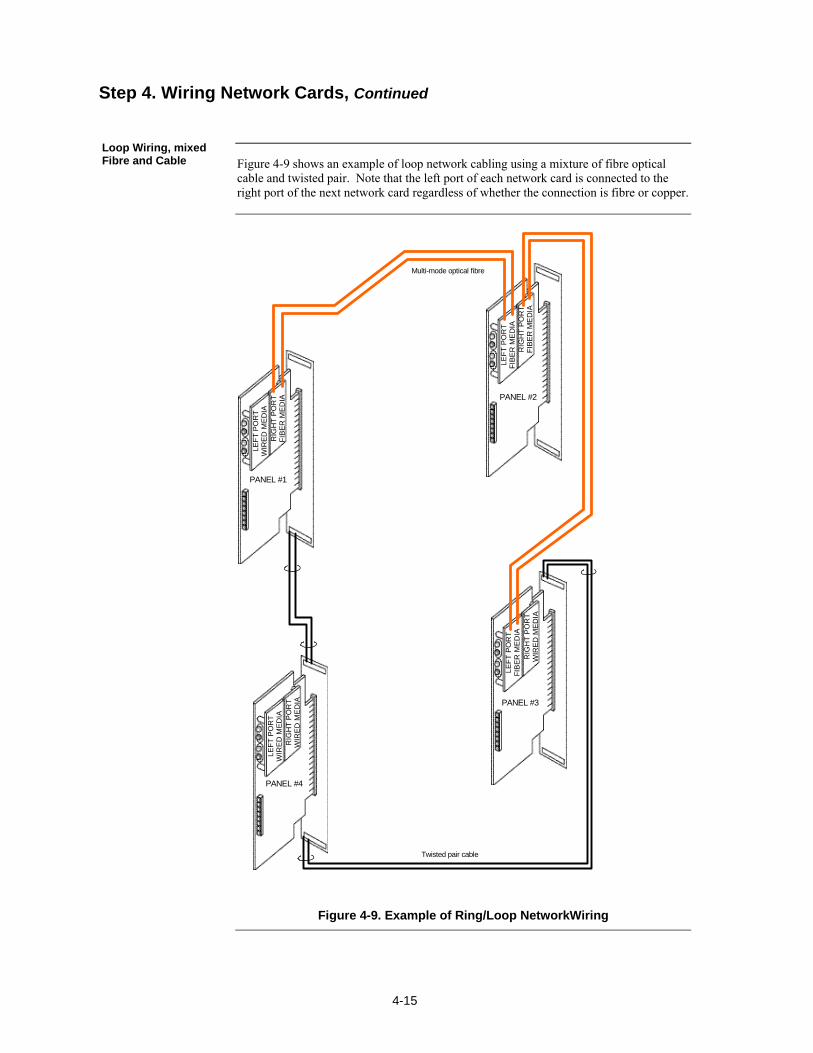
4-15
Figure 4-9 shows an example of loop network cabling using a mixture of fibre optical cable and twisted pair. Note that the left port of each network card is connected to the right port of the next network card regardless of whether the connection is fibre or copper.
PANEL #1
LEF
T P
OR
T
WIR
ED
ME
DIA
Twisted pair cable
RIG
HT
PO
RT
F
IBE
R M
ED
IA
LEF
T P
OR
T
FIB
ER
ME
DIA
RIG
HT
PO
RT
F
IBE
R M
ED
IA
LE
FT
PO
RT
F
IBE
R M
ED
IAR
IGH
T P
OR
T
WIR
ED
ME
DIA
RIG
HT
PO
RT
W
IRE
D M
ED
IA
LEF
T P
OR
T
WIR
ED
ME
DIA
PANEL #2
PANEL #3
PANEL #4
Multi-mode optical fibre
Figure 4-9. Example of Ring/Loop NetworkWiring
Step 4. Wiring Network Cards, Continued
Loop Wiring, mixed Fibre and Cable

4-16
5-1
The SPS is introduced in Chapter 2. A picture is shown in Figure 2.4. This chapter has the current and voltage ratings of the system power supply (SPS) and describes how it is installed and configured by the factory. It also describes the Alarm Relay Card that mounts onto the SPS to provide 3 extra relays.
Refer to the page number listed in this table for information on a specific topic.
Topic See Page #
SPS Specifications 5-2
SPS Configuration 5-4
SPS LED Indications 5-5
Troubleshooting an SPS 5-6
The Alarm Relay Card 5-7
Chapter 5 The System Power Supply & Alarm Relay Card
Introduction
In this Chapter
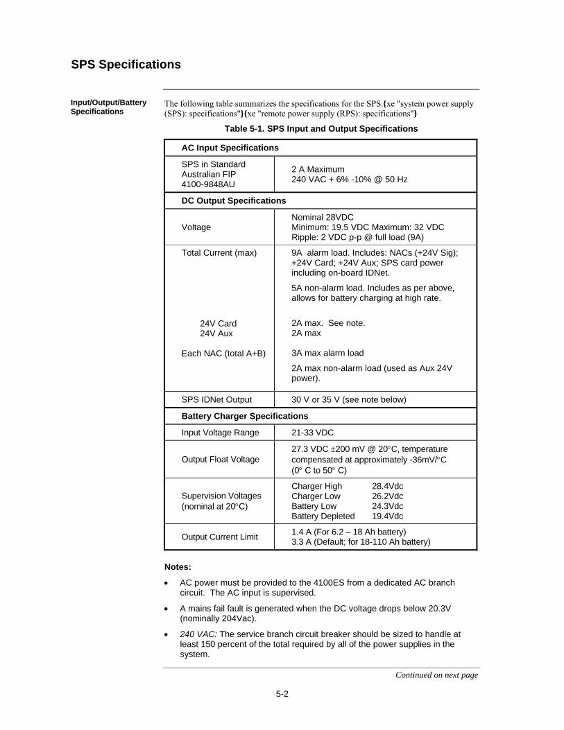
5-2
The following table summarizes the specifications for the SPS.xe "system power supply (SPS): specifications"xe "remote power supply (RPS): specifications"
Table 5-1. SPS Input and Output Specifications
AC Input Specifications
SPS in Standard Australian FIP 4100-9848AU
2 A Maximum 240 VAC + 6% -10% @ 50 Hz
DC Output Specifications
Voltage Nominal 28VDC Minimum: 19.5 VDC Maximum: 32 VDC Ripple: 2 VDC p-p @ full load (9A)
Total Current (max)
24V Card 24V Aux Each NAC (total A+B)
9A alarm load. Includes: NACs (+24V Sig); +24V Card; +24V Aux; SPS card power including on-board IDNet.
5A non-alarm load. Includes as per above, allows for battery charging at high rate.
2A max. See note. 2A max 3A max alarm load
2A max non-alarm load (used as Aux 24V power).
SPS IDNet Output 30 V or 35 V (see note below)
Battery Charger Specifications
Input Voltage Range 21-33 VDC
Output Float Voltage 27.3 VDC 200 mV @ 20C, temperature compensated at approximately -36mV/C (0 C to 50 C)
Supervision Voltages (nominal at 20C)
Charger High 28.4Vdc Charger Low 26.2Vdc Battery Low 24.3Vdc Battery Depleted 19.4Vdc
Output Current Limit 1.4 A (For 6.2 – 18 Ah battery) 3.3 A (Default; for 18-110 Ah battery)
Notes:
AC power must be provided to the 4100ES from a dedicated AC branch circuit. The AC input is supervised.
A mains fail fault is generated when the DC voltage drops below 20.3V (nominally 204Vac).
240 VAC: The service branch circuit breaker should be sized to handle at least 150 percent of the total required by all of the power supplies in the system.
Continued on next page
SPS Specifications
Input/Output/BatterySpecifications
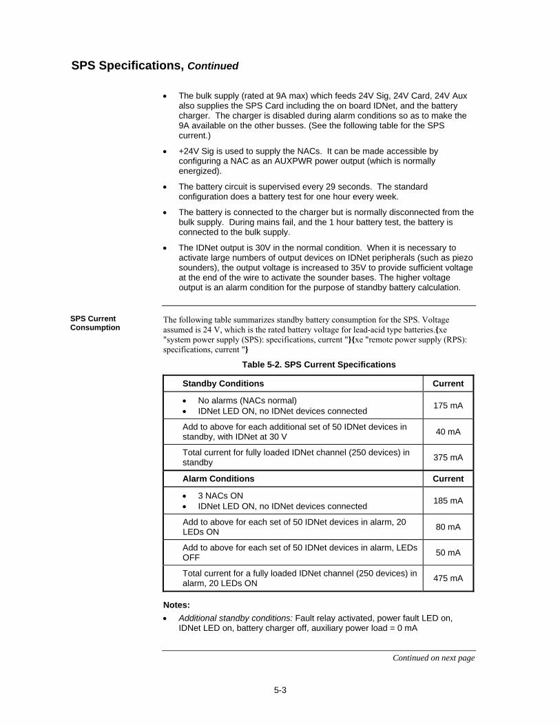
5-3
The bulk supply (rated at 9A max) which feeds 24V Sig, 24V Card, 24V Aux
also supplies the SPS Card including the on board IDNet, and the battery charger. The charger is disabled during alarm conditions so as to make the 9A available on the other busses. (See the following table for the SPS current.)
+24V Sig is used to supply the NACs. It can be made accessible by configuring a NAC as an AUXPWR power output (which is normally energized).
The battery circuit is supervised every 29 seconds. The standard configuration does a battery test for one hour every week.
The battery is connected to the charger but is normally disconnected from the bulk supply. During mains fail, and the 1 hour battery test, the battery is connected to the bulk supply.
The IDNet output is 30V in the normal condition. When it is necessary to activate large numbers of output devices on IDNet peripherals (such as piezo sounders), the output voltage is increased to 35V to provide sufficient voltage at the end of the wire to activate the sounder bases. The higher voltage output is an alarm condition for the purpose of standby battery calculation.
The following table summarizes standby battery consumption for the SPS. Voltage assumed is 24 V, which is the rated battery voltage for lead-acid type batteries.xe "system power supply (SPS): specifications, current "xe "remote power supply (RPS): specifications, current "
Table 5-2. SPS Current Specifications
Standby Conditions Current
No alarms (NACs normal) IDNet LED ON, no IDNet devices connected
175 mA
Add to above for each additional set of 50 IDNet devices in standby, with IDNet at 30 V
40 mA
Total current for fully loaded IDNet channel (250 devices) in standby
375 mA
Alarm Conditions Current
3 NACs ON IDNet LED ON, no IDNet devices connected
185 mA
Add to above for each set of 50 IDNet devices in alarm, 20 LEDs ON
80 mA
Add to above for each set of 50 IDNet devices in alarm, LEDs OFF
50 mA
Total current for a fully loaded IDNet channel (250 devices) in alarm, 20 LEDs ON
475 mA
Notes:
Additional standby conditions: Fault relay activated, power fault LED on, IDNet LED on, battery charger off, auxiliary power load = 0 mA
Continued on next page
SPS Specifications, Continued
SPS Current Consumption
5-4
Additional alarm conditions: Fault relay activated, power fault LED on, IDNet LED on, battery charger off, auxiliary power load = 0 mA, NAC alarm load = 0 mA, IDNet = 35 V
The range of possible temperatures under which the SPS may function are between 0 C and 50 C (120 F).
The SPS operates normally under non-condensing humidity conditions up to 93% relative humidity at 32° C.
xe "system power supply (SPS): configuring "xe "remote power supply (RPS): configuring "xe "card configuration: system power supply (SPS)"xe "card configuration: remote power supply (RPS)"
This section contains information about SPS jumpers, DIP switches and potentiometers.
P2: If the SPS IDNet outputs are being used, you may change P2 to configure the IDNet shield connection. Position 1 – 2 (bottom): Connects the shield to 0 V (default). Position 2 – 3 (top): Connects the shield to earth ground.
P3: City Card and Relay Card operation Position 1-2 (top): Install in pos. 1-2 only if a relay card 4100-6033 is installed and
has relay 3 programmed for operation other than "Fault (Trouble)" Position 2-3 (bottom): (default) For use with 4100-6033 if relay 3 is programmed for
"activate on fault (trouble)" operation. (This option is used for Brigade connection) P1: Earth connect jumper. Position 1 – 2 (rhs): Enables Earth fault monitoring. Set to this position unless the
system uses a TrueAlert Power Supply under common 0 V. Position 2 – 3 (lhs): Disables Earth fault monitoring. Set to this position only if the
system uses a TrueAlert Power Supply under common 0 V.
Refer to Appendix A to set the device address for the SPS with DIP switch SW1.
There are two small potentiometers on the 4100-9848AU SPS, situated below the centre of the PCB. These are adjusted in the factory and typically will not need adjusting in the field. If it is necessary to adjust them, turning the potentiometer clockwise increases the setting. R341 Battery Charger Voltage Adjust this potentiometer to achieve a charger voltage of 27.3V 0.1V at 20C. (Allow -36mV/C for temperatures different to 20C). Disconnect the battery while making this adjustment, and measure the charger output at the SPS terminals. Reconnect the battery after making the adjustment.
SPS Specifications, Continued
Environmental Requirements
SPS Configuration
Overview
Jumper Settings
Setting the Device Address
Adjusting Voltages

5-5
R342 Voltage Measurement Calibration Adjust this potentiometer to match the indication of charger voltage on the panel user interface with that on a calibrated voltmeter measuring the charger output. Use the “Card Status” option of the menu. Match the two readings to within 0.05V DC.
The SPS has the following LED indicators: xe "system power supply (SPS): LEDs"xe "remote power supply (RPS): LEDs" LED1 (yellow). Illuminates when NAC 1 is ON or in Fault.
LED2 (yellow). Illuminates when NAC 2 is ON or in Fault.
LED3 (yellow). Illuminates when NAC 3 is ON or in Fault.
LED4 (yellow). Illuminates to indicate a communications loss with the system CPU; normally off. If this LED is blinking, try re-loading the slave exec from the master.
LED5 (yellow). Indicates IDNet status.
Slow blink: Class A open circuit Fault.
Fast blink: Short circuit Fault.
On steady: No devices detected/ channel failure.
Normally off.
LED6 (yellow). Indicates power supply status.
Single blink: Positive earth fault.
Double blink: Negative earth fault.
Triple blink: Battery Fault.
Quadruple blink: Charger Fault.
On steady: Overcurrent fault.
Normally off.
LED7 (green). Illuminates when the power supply is powered from the AC line. Off when the mains is off, or when it is using battery backup power.
SPS LED Indications
LEDs

5-6
This section contains explanations of fault messages that may appear on the 4100ES user interface when using the SPS. Heading text in the left margin shows the error message, while the paragraph next to it describes the likely cause of the message.
There is no output voltage from the power supply.
Appears if one or more extra devices are present on the loop, i.e., devices that have not been configured for the IDNet channel.. Only one message appears, regardless of the number of extra devices found.
There is an open circuit fault detected on the IDNet channel. A hardware reset is required to reset the fault indication.
Comes up during the Earth Fault Search diagnostic function. Once the search is initiated, the front panel display indicates how far along the search process has progressed (10%, 25%… 75%), and then shows the results of the search. The result either identifies the offending circuit or indicates that the earth fault could not be found. SPS circuits (IDNet, NAC, and aux power) are searched. System alarm and fault processing is suspended during the search.
Appears when a short circuit fault is detected on the IDNet channel. This status clears automatically when the short circuit is removed.
Appears when each device on the IDNet channel has been configured, but none of the configured devices are communicating on the channel. This message does not appear if there are no configured devices on the IDNet channel.
Occurs when the 4100ES is put into a diagnostic mode and finds a device not responding, or responding unreliably. Refer to the 4100 Fault Finding Guide (LT0565) for information on how to perform this diagnostic.
Occurs when 24V is not present on TrueAlarm devices or when TrueAlarm sensor bases with relay driver outputs are not properly supervised or when isolator devices are in isolation mode.
Troubleshooting an SPS
Overview
IDNet Power Monitor Trouble
Extra Device
Class A Trouble
Earth Fault Search
Short Circuit
Channel Fail
No Answer/ Bad Answer
Output Abnormal
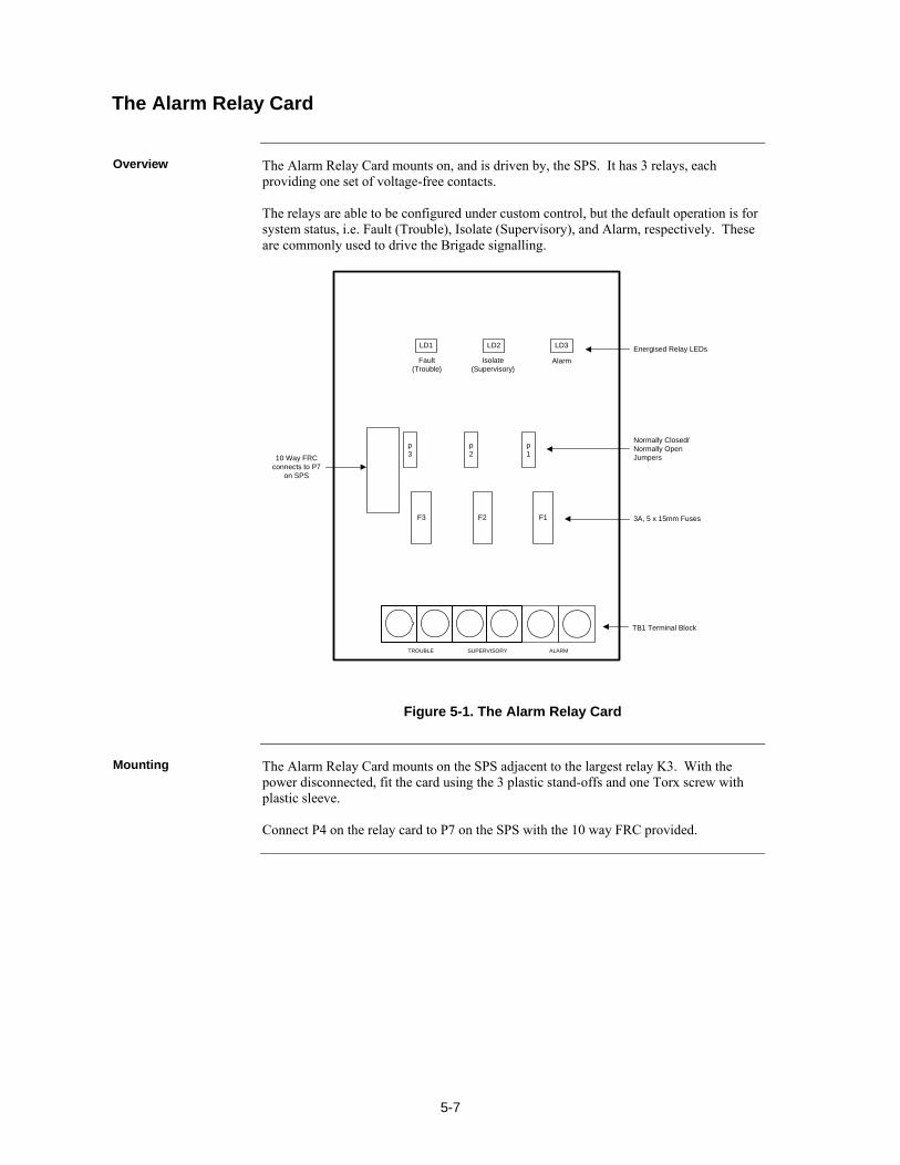
5-7
The Alarm Relay Card mounts on, and is driven by, the SPS. It has 3 relays, each providing one set of voltage-free contacts. The relays are able to be configured under custom control, but the default operation is for system status, i.e. Fault (Trouble), Isolate (Supervisory), and Alarm, respectively. These are commonly used to drive the Brigade signalling.
TROUBLE SUPERVISORY ALARM
F3 F2 F1
p3
p2
p1
LD1 LD2 LD3
Fault(Trouble)
Isolate(Supervisory)
Alarm
10 Way FRC connects to P7
on SPS
Energised Relay LEDs
Normally Closed/Normally OpenJumpers
3A, 5 x 15mm Fuses
TB1 Terminal Block
Figure 5-1. The Alarm Relay Card
The Alarm Relay Card mounts on the SPS adjacent to the largest relay K3. With the power disconnected, fit the card using the 3 plastic stand-offs and one Torx screw with plastic sleeve. Connect P4 on the relay card to P7 on the SPS with the 10 way FRC provided.
The Alarm Relay Card
Overview
Mounting
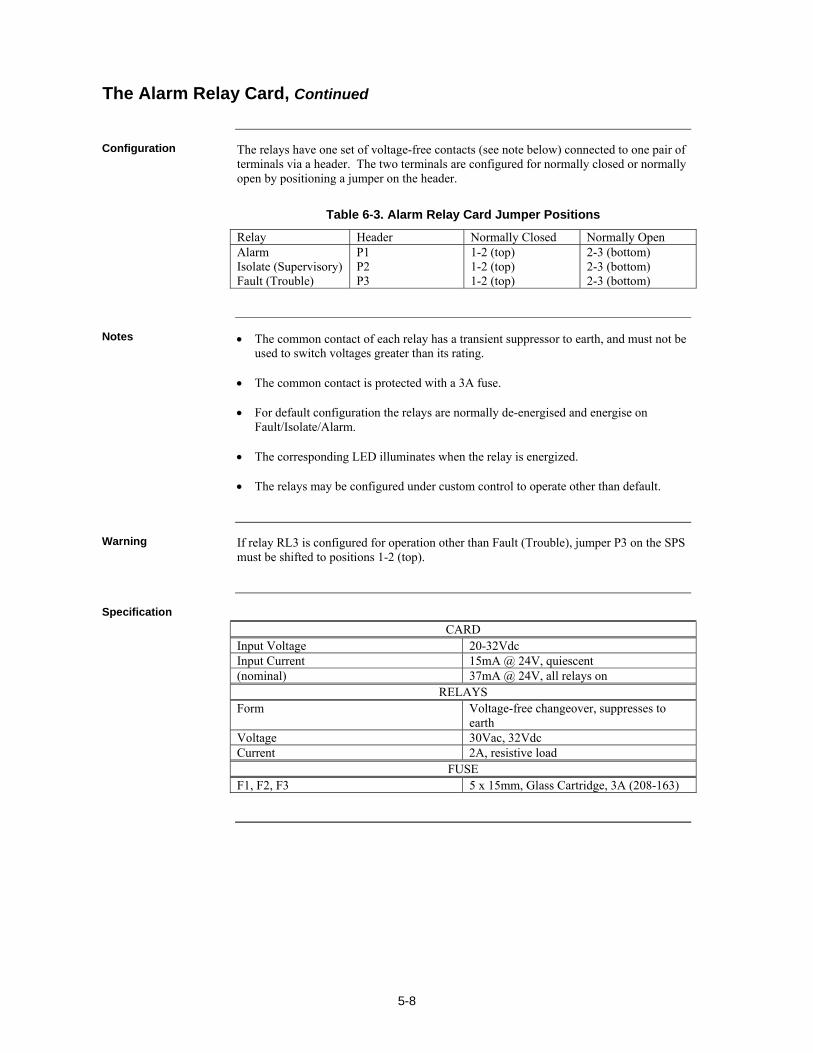
5-8
The relays have one set of voltage-free contacts (see note below) connected to one pair of terminals via a header. The two terminals are configured for normally closed or normally open by positioning a jumper on the header.
Table 6-3. Alarm Relay Card Jumper Positions
Relay Header Normally Closed Normally Open Alarm Isolate (Supervisory) Fault (Trouble)
P1 P2 P3
1-2 (top) 1-2 (top) 1-2 (top)
2-3 (bottom) 2-3 (bottom) 2-3 (bottom)
The common contact of each relay has a transient suppressor to earth, and must not be used to switch voltages greater than its rating.
The common contact is protected with a 3A fuse.
For default configuration the relays are normally de-energised and energise on Fault/Isolate/Alarm.
The corresponding LED illuminates when the relay is energized.
The relays may be configured under custom control to operate other than default.
If relay RL3 is configured for operation other than Fault (Trouble), jumper P3 on the SPS must be shifted to positions 1-2 (top).
CARD
Input Voltage 20-32VdcInput Current 15mA @ 24V, quiescent (nominal) 37mA @ 24V, all relays on
RELAYS Form Voltage-free changeover, suppresses to
earth Voltage 30Vac, 32Vdc Current 2A, resistive load
FUSE F1, F2, F3 5 x 15mm, Glass Cartridge, 3A (208-163)
The Alarm Relay Card, Continued
Configuration
Notes
Warning
Specification

6-1
This chapter shows how various devices are wired to an SPS. It includes connection to NACs, IDNet, relays, and power circuits.
Refer to the page number listed in this table for information on a specific topic.
Topic See Page #
General Field Wiring Guidelines 6-2
SPS NAC Field Wiring Guidelines 6-3
Power Supply Wiring Distances 6-6
Using T-GEN 50 with 4100ES 6-8
SPS Auxiliary Power Wiring 6-15
SPS Relay Wiring 6-17
Chapter 6 SPS Field Wiring (4100ES)
Introduction
In this Chapter

6-2
Make sure these guidelines are accounted for before wiring: All field wires must be 0.75 mm2 or greater and comply with AS 1670.1 and the
wiring code.
Conductors must test free of all grounds.
All wiring must be done using copper conductors only, unless noted otherwise.
If shielded wire is used,
- the metallic continuity of the shield must be maintained throughout the entire cable length.
- the entire length of the cable must have a resistance greater than 1 Megohm to earth ground.
Underground wiring must be free of all water.
In areas of high lightning activity, or in areas that have large power surges, the 2081-9027 Transient Suppressor should be used on monitor points.
Wires that run in plenum should be in conduit.
A system ground must be provided for earth detection and lightning protection devices. This connection must comply with approved earth detection.
Only system wiring should be run together in the same conduit.
Use supplied ferrite beads with all SPS field wiring including the Aux 24V. Loop wires twice through the supplied ferrite bead(s) as shown in Figure 6-1. (See Appendix K for ordering part numbers.)
Figure 6-1. The Ferrite Bead
Continued on next page
General Field Wiring Guidelines
General Guidelines
Wires go twice through (1 turn)

6-3
Each of the 3 NACs has two pairs of driven outputs (A+/A-, B+/B-) which operate together. NAC B outputs have polarity reversal supervision and expect a 10k EOLR. Each connected device must have a suitably rated blocking diode. NAC A outputs have an integral 10kΩ to accommodate Class A (loop) wiring. Class A wiring is not mandatory under AS 1670.1. The 3A max rating applies to each NAC, B + A outputs combined. NAC load current may be read on the LCD. The Australian SPS has extra decoupling capacitors fitted to the NAC outputs, and cannot be used to drive the Simplex range of addressable appliances. NACs may be programmed to be normally on and the terminals used as power supply outputs. See the SPS Auxiliary Power Wiring section following. xe "guidelines for wiring: NACs"xe "NACs: guidelines for wiring"xe "wiring: guidelines (NACs)"xe "NACs: guidelines for wiring"
These rules apply to NAC field wiring: All wiring should be 0.75 mm2 to 4 mm2.
All wiring is supervised and power-limited.
The maximum alarm current is 3A per circuit. The supervisory current is 2mA at 24 VDC.
The nominal voltage rating is 24 VDC, 2V p-p ripple (maximum).
The total available current (Card Power + NAC power + AUX Power outputs) from the SPS is 9A.
Terminal designations “+” and “-” are for the alarm state of the NAC, not the supervision/idle state.
Continued on next page
SPS NAC Field Wiring Guidelinesxe "wiring: distances, Class A (NAC)"xe "NACs: wiring distances (Class A)"xe "Class A wiring: distances (NAC)"
Overview
Guidelines
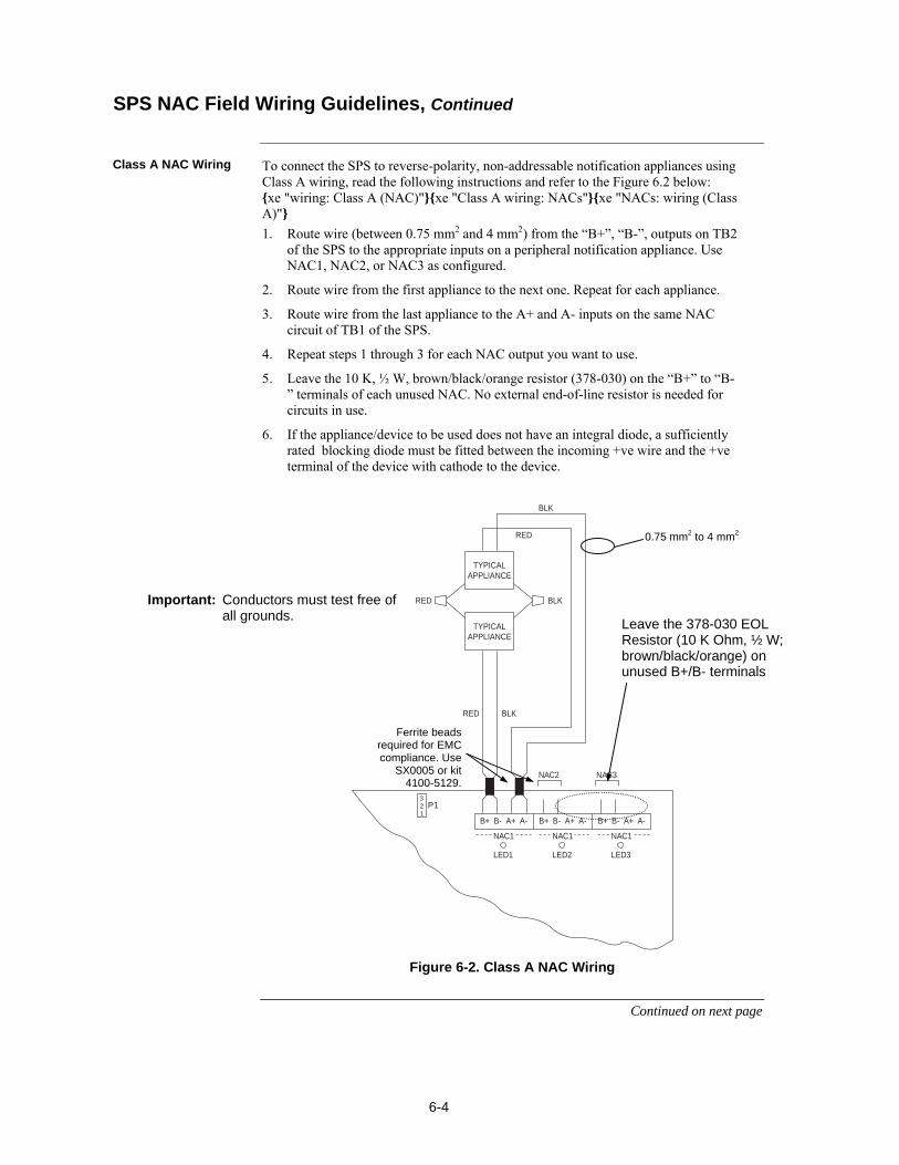
6-4
To connect the SPS to reverse-polarity, non-addressable notification appliances using Class A wiring, read the following instructions and refer to the Figure 6.2 below: xe "wiring: Class A (NAC)"xe "Class A wiring: NACs"xe "NACs: wiring (Class A)"
1. Route wire (between 0.75 mm2 and 4 mm2) from the “B+”, “B-”, outputs on TB2 of the SPS to the appropriate inputs on a peripheral notification appliance. Use NAC1, NAC2, or NAC3 as configured.
2. Route wire from the first appliance to the next one. Repeat for each appliance.
3. Route wire from the last appliance to the A+ and A- inputs on the same NAC circuit of TB1 of the SPS.
4. Repeat steps 1 through 3 for each NAC output you want to use.
5. Leave the 10 K, ½ W, brown/black/orange resistor (378-030) on the “B+” to “B-” terminals of each unused NAC. No external end-of-line resistor is needed for circuits in use.
6. If the appliance/device to be used does not have an integral diode, a sufficiently rated blocking diode must be fitted between the incoming +ve wire and the +ve terminal of the device with cathode to the device.
P1321
B+ B- A+ A-
TYPICALAPPLIANCE
RED
RED
RED
NAC1
B+ B- A+ A-
NAC1
B+ B- A+ A-
NAC1
LED1 LED2 LED3
TYPICALAPPLIANCE
BLK
BLK
BLK
NAC2 NAC3
Figure 6-2. Class A NAC Wiring
Continued on next page
SPS NAC Field Wiring Guidelines, Continued
Class A NAC Wiring
0.75 mm2 to 4 mm2
Important: Conductors must test free of all grounds.
Leave the 378-030 EOL Resistor (10 K Ohm, ½ W; brown/black/orange) on unused B+/B- terminals
Ferrite beads required for EMC compliance. Use
SX0005 or kit 4100-5129.
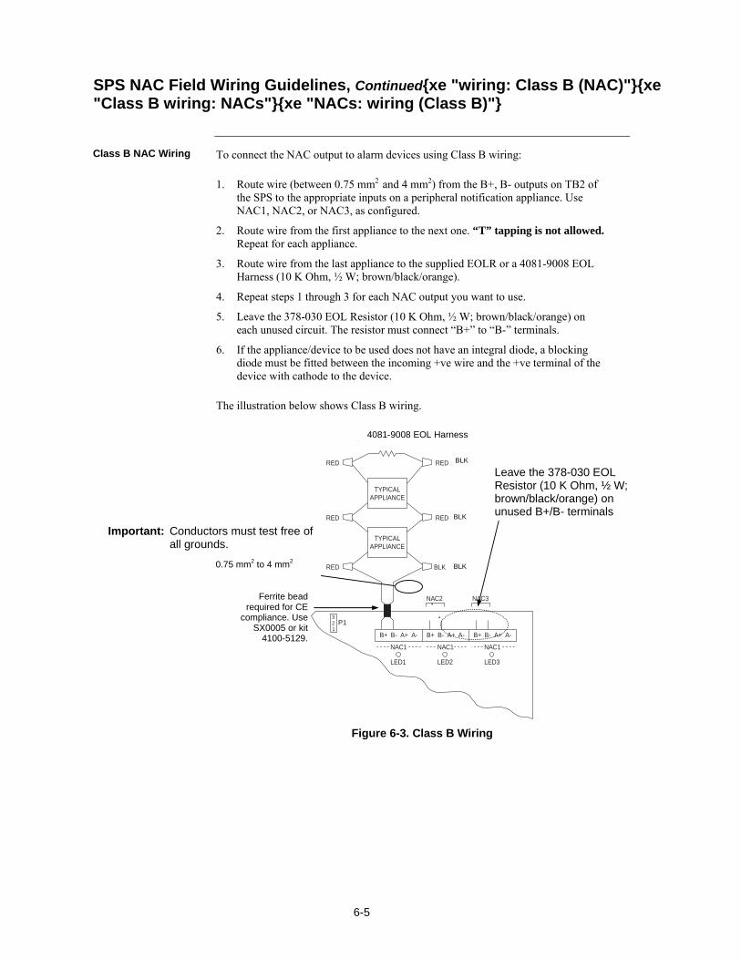
6-5
To connect the NAC output to alarm devices using Class B wiring:
1. Route wire (between 0.75 mm2 and 4 mm2) from the B+, B- outputs on TB2 of the SPS to the appropriate inputs on a peripheral notification appliance. Use NAC1, NAC2, or NAC3, as configured.
2. Route wire from the first appliance to the next one. “T” tapping is not allowed. Repeat for each appliance.
3. Route wire from the last appliance to the supplied EOLR or a 4081-9008 EOL Harness (10 K Ohm, ½ W; brown/black/orange).
4. Repeat steps 1 through 3 for each NAC output you want to use.
5. Leave the 378-030 EOL Resistor (10 K Ohm, ½ W; brown/black/orange) on each unused circuit. The resistor must connect “B+” to “B-” terminals.
6. If the appliance/device to be used does not have an integral diode, a blocking diode must be fitted between the incoming +ve wire and the +ve terminal of the device with cathode to the device.
The illustration below shows Class B wiring.
P1321
B+ B- A+ A-
TYPICALAPPLIANCE
RED BLK
NAC1
B+ B- A+ A-
NAC1
B+ B- A+ A-
NAC1
LED1 LED2 LED3
TYPICALAPPLIANCE
10K 1/2W (133-894)
NAC2 NAC3
RED RED
RED RED
Figure 6-3. Class B Wiring
SPS NAC Field Wiring Guidelines, Continuedxe "wiring: Class B (NAC)"xe "Class B wiring: NACs"xe "NACs: wiring (Class B)"
Class B NAC Wiring
Important: Conductors must test free of all grounds.
0.75 mm2 to 4 mm2
BLK
BLK
BLK
4081-9008 EOL Harness
Leave the 378-030 EOL Resistor (10 K Ohm, ½ W; brown/black/orange) on unused B+/B- terminals
Ferrite bead required for CE
compliance. Use SX0005 or kit
4100-5129.

6-6
Before wiring from any type of power supply to notification appliances, check Tables 6-1 and 6-2 for wiring distances.
Table 6-1 lists the maximum distances from the NAC terminal block to the last appliance in a Class A configuration, depending on wire gauge and current. Use Table 6-1 to calculate wire distances for your application if you are using Class A wiring.
Table 6-1. Class A Wiring Distances
Alarm Current @
24V
0.75 mm2 1.00 mm2 1.50 mm2 2.50 mm2 4.00 mm2 DC Resistance
0.25A 120m 150m 230m 380m 620m 6.0 ohms 0.50A 58m 77m 120m 190m 310m 3.0 ohms 0.75A 38m 51m 77m 130m 210m 2.0 ohms 1.00A 29m 38m 58m 96m 150m 1.5 ohms 1.25A 23m 31m 46m 77m 120m 1.2 ohms 1.50A 19m 26m 38m 64m 100m 1.0 ohms 1.75A 16m 22m 33m 55m 88m 0.86 ohms 2.00A 14m 19m 29m 48m 77m 0.75 ohms 2.25A 13m 17m 26m 43m 68m 0.67 ohms 2.50A 12m 15m 23m 38m 62m 0.60 ohms 2.75A 10m 14m 21m 35m 56m 0.55 ohms 3.00A 10m 13m 19m 32m 51m 0.50 ohms
Notes:
Max Distance = distance from SPS to last appliance.
This table is calculated at 50°C.
Distances are based on a 3V drop, and take into account the worst-case panel output voltage. These distances are worst case to allow for one single load at the furthest point.
If circuit integrity wire is used instead of housing cable in a fire rated enclosure, reduce wiring distances by 12m for every 3m of potential exposure.
Continued on next page
Power Supply Wiring Distancesxe "wiring: distances, Class A (NAC)"xe "NACs: wiring distances (Class A)"xe "Class A wiring: distances (NAC)"
Overview
Class A NAC Wiring Table

6-7
Table 6-2 lists the maximum distances from the NAC terminal block to the last appliance in a Class B configuration, depending on wire gauge and current. Use Table 6-2 to calculate wire distances for your application if you are using Class B wiring.
Table 6-2. Class B Wiring Distances
Alarm Current @
24V 0.75 mm2 1.00 mm2 1.50 mm2 2.50 mm2 4.00 mm2
DC Resistance
0.25A 230m 310m 460m 770m 1200m 12.0 ohms 0.50A 120m 150m 230m 380m 620m 6.0 ohms 0.75A 77m 100m 150m 260m 410m 4.0 ohms 1.00A 58m 77m 120m 190m 310m 3.0 ohms 1.25A 46m 62m 92m 150m 250m 2.4 ohms 1.50A 38m 51m 77m 130m 210m 2.0 ohms 1.75A 33m 44m 66m 110m 180m 1.7 ohms 2.00A 29m 38m 58m 96m 150m 1.5 ohms 2.25A 26m 34m 51m 85m 140m 1.3 ohms 2.50A 23m 31m 46m 77m 120m 1.2 ohms 2.75A 21m 28m 42m 70m 110m 1.1 ohms 3.00A 19m 26m 38m 64m 100m 1.0 ohms
Notes:
Max Distance = distance from SPS to last appliance.
This table is calculated at 50°C.
Distances are based on a 3V drop, and take into account the worst-case panel output voltage. These distances are worst case to allow for one single load at the furthest point.
If circuit integrity wire is used instead of housing cable in a fire rated enclosure, reduce wiring distances by 12m for every 3m of potential exposure.
Continued on next page
Power Supply Wiring Distances, Continuedxe "wiring: distances, Class B (NAC)"xe "NACs: wiring distances (Class B)"xe "Class B wiring: distances (NAC)"
Class B NAC Wiring Table
6-8
AS 1670.1 requires fire alarm warning systems to produce sounds complying with AS 2220 or ISO 8201. One way of meeting this requirement in a 4100ES system is to use a T-GEN 50 tone generator, which is capable of driving up to 50W of load on a 100V speaker line. The recommended version of the T-GEN 50 for use in 4100ES-S1 is available as part 4100-0766K. This consists of a T-GEN 50 mounted on a metal bracket which is mounted into the expansion bay in the same way as a legacy 4100 motherboard. This part code includes the necessary mounting hardware. The best place to mount this bracket is in the right-most free slot in the expansion bay, next to the mains socket bracket. The bracket should be installed with the T-GEN 50 facing to the left - this is “upside down” compared to some other uses of this bracket. Note also that the heat sink of the T-GEN 50 intrudes slightly into the space above the next slot to the left. This will probably clash with other motherboards or modules and make this slot unusable. The T-GEN 50 must be continuously powered from nominal 24VDC, i.e., not just during Alarm conditions, so that it can supervise the 100V speaker line. The recommended method is to power the T-GEN 50 from the AUX POWER terminals of the SPS power supply. This output is rated at 2A, which is just sufficient to drive one fully loaded T-GEN 50. However, this leaves no reserve for any other equipment to be powered from these terminals, e.g., a brigade signalling device. If 24V DC is required for other ancillary devices as well, this can be supplied from one of the NAC outputs via the Fused Distribution Board PA0915. The wiring for this is shown in Figure 6-4.
Continued on next page
Using T-GEN 50 with 4100ES
Overview
Powering the T-GEN 50
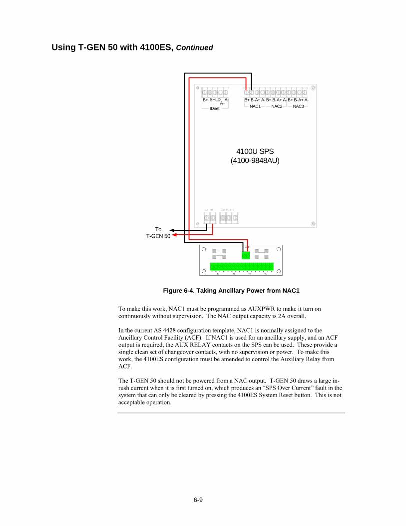
6-9
24V IN
+- +- +- +- +- +- +- +-F4 F1F3 F2
B+ B-A+ A-
NAC1
B+ B-A+ A-
NAC2
B+ B-A+ A-
NAC3
B+ A-
IDnet
SHLDA+
4100U SPS(4100-9848AU)
To T-GEN 50
Figure 6-4. Taking Ancillary Power from NAC1
To make this work, NAC1 must be programmed as AUXPWR to make it turn on continuously without supervision. The NAC output capacity is 2A overall. In the current AS 4428 configuration template, NAC1 is normally assigned to the Ancillary Control Facility (ACF). If NAC1 is used for an ancillary supply, and an ACF output is required, the AUX RELAY contacts on the SPS can be used. These provide a single clean set of changeover contacts, with no supervision or power. To make this work, the 4100ES configuration must be amended to control the Auxiliary Relay from ACF.
The T-GEN 50 should not be powered from a NAC output. T-GEN 50 draws a large in-rush current when it is first turned on, which produces an “SPS Over Current” fault in the system that can only be cleared by pressing the 4100ES System Reset button. This is not acceptable operation.
Using T-GEN 50 with 4100ES, Continued
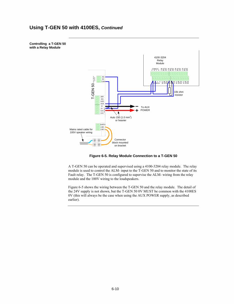
6-10
Connector block mounted
on bracket
T-G
EN 5
010k ohm resistor
LINE -LINE +
EARTH
DC
INPU
T
+24V+24V0V0VALM-A/I/E-SIGDEF-
FAU
LT R
ELAY
O
UTP
UT
COMNCNO
To AUX POWER
4100-3204 Relay
Module
Mains rated cable for 100V speaker wiring
Auto 150 (1.0 mm2) or heavier
FEEDBACK1- 1+2- 2+
FEEDBACK3- 3+4- 4+
RELAY 3ANO NCC
RELAY 3BNO NCC
RELAY 4ANO NCC
RELAY 4BNO NCC
RELAY 1ANO NCC
RELAY 1BNO NCC
RELAY 2ANO NCC
RELAY 2BNO NCC
Figure 6-5. Relay Module Connection to a T-GEN 50
A T-GEN 50 can be operated and supervised using a 4100-3204 relay module. The relay module is used to control the ALM- input to the T-GEN 50 and to monitor the state of its Fault relay. The T-GEN 50 is configured to supervise the ALM- wiring from the relay module and the 100V wiring to the loudspeakers. Figure 6-5 shows the wiring between the T-GEN 50 and the relay module. The detail of the 24V supply is not shown, but the T-GEN 50 0V MUST be common with the 4100ES 0V (this will always be the case when using the AUX POWER supply, as described earlier).
Using T-GEN 50 with 4100ES, Continued
Controlling a T-GEN 50 with a Relay Module
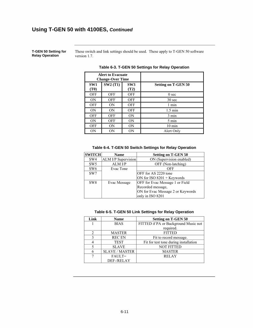
6-11
These switch and link settings should be used. These apply to T-GEN 50 software version 1.7.
Table 6-3. T-GEN 50 Settings for Relay Operation
Alert to Evacuate Change-Over Time
SW1 (T0)
SW2 (T1) SW3 (T2)
Setting on T-GEN 50
OFF OFF OFF 0 sec ON OFF OFF 30 sec OFF ON OFF 1 min
ON ON OFF 1.5 min OFF OFF ON 3 min ON OFF ON 5 min OFF ON ON 10 min ON ON ON Alert Only
Table 6-4. T-GEN 50 Switch Settings for Relay Operation
SWITCH Name Setting on T-GEN 50 SW4 ALM I/P Supervision ON (Supervision enabled) SW5 ALM I/P OFF (Non-latching) SW6 Evac Tone OFF SW7 OFF for AS 2220 tone
ON for ISO 8201 + Keywords SW8 Evac Message OFF for Evac Message 1 or Field
Recorded message, ON for Evac Message 2 or Keywords only in ISO 8201
Table 6-5. T-GEN 50 Link Settings for Relay Operation
Link Name Setting on T-GEN 50 1 BIAS FITTED if PA or Background Music not
required. 2 MASTER FITTED3 REC EN Fit to record message. 4 TEST Fit for test tone during installation 5 SLAVE NOT FITTED 6 SLAVE / MASTER MASTER 7 FAULT=
DEF-/RELAY RELAY
Using T-GEN 50 with 4100ES, Continued
T-GEN 50 Setting for Relay Operation
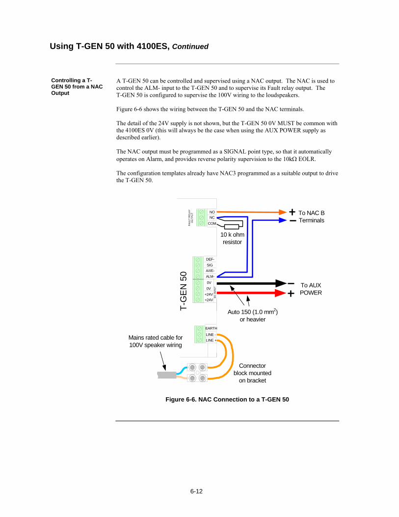
6-12
A T-GEN 50 can be controlled and supervised using a NAC output. The NAC is used to control the ALM- input to the T-GEN 50 and to supervise its Fault relay output. The T-GEN 50 is configured to supervise the 100V wiring to the loudspeakers. Figure 6-6 shows the wiring between the T-GEN 50 and the NAC terminals. The detail of the 24V supply is not shown, but the T-GEN 50 0V MUST be common with the 4100ES 0V (this will always be the case when using the AUX POWER supply as described earlier). The NAC output must be programmed as a SIGNAL point type, so that it automatically operates on Alarm, and provides reverse polarity supervision to the 10k EOLR. The configuration templates already have NAC3 programmed as a suitable output to drive the T-GEN 50.
Mains rated cable for 100V speaker wiring
Connector block mounted
on bracket
T-G
EN
50
10 k ohm resistor
Auto 150 (1.0 mm2) or heavier
LINE -
LINE +
EARTH
DC
IN
PU
T
+24V
+24V
0V
0V
ALM-
A/I/E-
SIG
DEF-
FA
UL
T R
EL
AY
O
UT
PU
T
COM
NC
NO
To AUX POWER
To NAC B Terminals
Figure 6-6. NAC Connection to a T-GEN 50
Using T-GEN 50 with 4100ES, Continued
Controlling a T-GEN 50 from a NAC Output
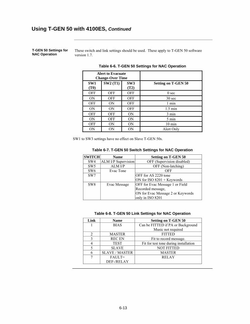
6-13
These switch and link settings should be used. These apply to T-GEN 50 software version 1.7.
Table 6-6. T-GEN 50 Settings for NAC Operation
Alert to Evacuate Change-Over Time
SW1 (T0)
SW2 (T1) SW3 (T2)
Setting on T-GEN 50
OFF OFF OFF 0 sec
ON OFF OFF 30 sec OFF ON OFF 1 min
ON ON OFF 1.5 min
OFF OFF ON 3 min ON OFF ON 5 min OFF ON ON 10 min ON ON ON Alert Only
SW1 to SW3 settings have no effect on Slave T-GEN 50s.
Table 6-7. T-GEN 50 Switch Settings for NAC Operation
SWITCH Name Setting on T-GEN 50 SW4 ALM I/P Supervision OFF (Supervision disabled) SW5 ALM I/P OFF (Non-latching) SW6 Evac Tone OFF SW7 OFF for AS 2220 tone
ON for ISO 8201 + Keywords SW8 Evac Message OFF for Evac Message 1 or Field
Recorded message, ON for Evac Message 2 or Keywords only in ISO 8201
Table 6-8. T-GEN 50 Link Settings for NAC Operation
Link Name Setting on T-GEN 50 1 BIAS Can be FITTED if PA or Background
Music not required 2 MASTER FITTED 3 REC EN Fit to record message. 4 TEST Fit for test tone during installation 5 SLAVE NOT FITTED 6 SLAVE / MASTER MASTER 7 FAULT=
DEF-/RELAY RELAY
Using T-GEN 50 with 4100ES, Continued
T-GEN 50 Settings for NAC Operation
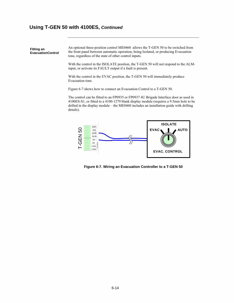
6-14
An optional three-position control ME0460 allows the T-GEN 50 to be switched from the front panel between automatic operation, being Isolated, or producing Evacuation tone, regardless of the state of other control inputs. With the control in the ISOLATE position, the T-GEN 50 will not respond to the ALM- input, or activate its FAULT output if a fault is present. With the control in the EVAC position, the T-GEN 50 will immediately produce Evacuation tone. Figure 6-7 shows how to connect an Evacuation Control to a T-GEN 50. The control can be fitted to an FP0935 or FP0937 4U Brigade Interface door as used in 4100ES-S1, or fitted to a 4100-1279 blank display module (requires a 9.5mm hole to be drilled in the display module – the ME0460 includes an installation guide with drilling details).
T-G
EN
50
DC
IN
PU
T
+24V
+24V
0V
0V
ALM-
A/I/E-
SIG
DEF-
EVAC. CONTROL
EVAC
ISOLATE
AUTO
Figure 6-7. Wiring an Evacuation Controller to a T-GEN 50
Using T-GEN 50 with 4100ES, Continued
Fitting an EvacuationControl

6-15
The panel, battery-backed, unregulated dc bulk power is available from the SPS via the NAC and the 24V Aux power terminals (1 pair only, as in Figure 6-8). NACs not configured as switched outputs may be configured as auxiliary power point type in the 4100 Programmer. All of these are power-limited.
Review the following guidelines before using the SPS for auxiliary power: xe "wiring: SPS auxiliary power"xe "wiring: RPS auxiliary power"xe "remote power supply (RPS): wiring, auxiliary power"xe "system power supply (SPS): wiring, auxiliary power"xe "wiring: auxiliary power"xe "auxiliary power: RPS"xe "auxiliary power: SPS"
Voltage rating: 24 VDC (nominal), 2 V P-P ripple (maximum).
The total auxiliary current available for non-alarm is 5 A. The total current available for the entire SPS is 9 A, including NAC, auxiliary, and card power.
All wiring is 0.75 mm2 to 4 mm2.
All SPS powered field wiring requires a ferrite bead (refer Fig 6.1).
All wiring that leaves the building requires overvoltage protection. Install module 2081-9044 wherever wire enters or exits the building. A maximum of four 2081-9044 Modules may be connected to one channel.
When a NAC is configured as an auxiliary power circuit, no end-of-line resistor is used.
External wiring is not supervised unless an end-of-line relay is wired, coil to auxiliary power, and Normally Open contacts are monitored by a system power point. Relay current must be considered as part of the load.
Programming is required for the dedicated Auxiliary Power output (TB3).
The following devices may be connected to the 2A Auxiliary Power: - 2190-series monitor and signal ZAMs - 4090-series IDNet ZAMs - 4098-series four-wire smoke detectors and duct detectors - 4190-9050 4-20 mA MZAM - 4603-9101 LCD Annunciator
The Auxiliary Power output is rated at 2 A dc.
Where multiple loads are to be connected with individual protection, a Fused DC Distribution board may be fitted directly to the SPS bracket adjacent to TB3.
Continued on next page
SPS Auxiliary Power Wiring
Overview
Guidelines
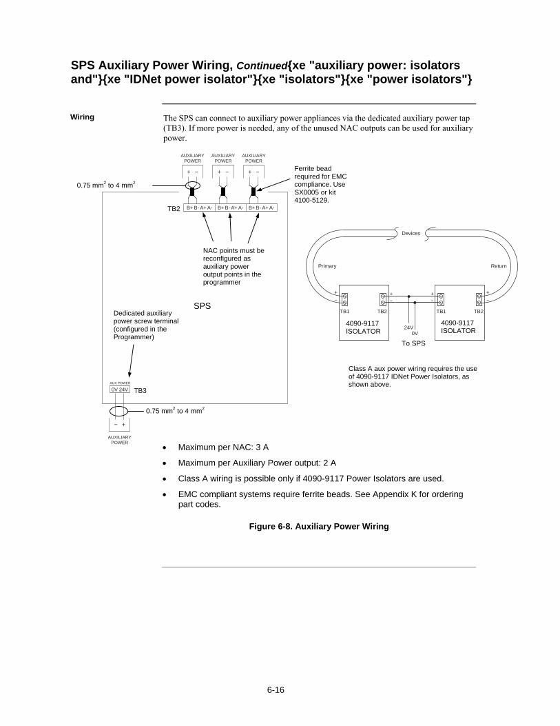
6-16
The SPS can connect to auxiliary power appliances via the dedicated auxiliary power tap (TB3). If more power is needed, any of the unused NAC outputs can be used for auxiliary power.
B+
0V 24VAUX POWER
B- A+ A- B+ B- A+ A- B+ B- A+ A-
AUXILIARYPOWER
AUXILIARYPOWER
AUXILIARYPOWER
AUXILIARYPOWER
Figure 6-8. Auxiliary Power Wiring
SPS Auxiliary Power Wiring, Continuedxe "auxiliary power: isolators and"xe "IDNet power isolator"xe "isolators"xe "power isolators"
Wiring
Maximum per NAC: 3 A
Maximum per Auxiliary Power output: 2 A
Class A wiring is possible only if 4090-9117 Power Isolators are used.
EMC compliant systems require ferrite beads. See Appendix K for ordering part codes.
Devices
Primary Return
TB1 TB2
24V0V
TB1 TB2
To SPS
Class A aux power wiring requires the use of 4090-9117 IDNet Power Isolators, as shown above.
4090-9117 ISOLATOR
4090-9117 ISOLATOR
SPS
TB2
TB3
Dedicated auxiliary power screw terminal (configured in the Programmer)
NAC points must be reconfigured as auxiliary power output points in the programmer
0.75 mm2 to 4 mm2
0.75 mm2 to 4 mm2
Ferrite bead required for EMC compliance. Use SX0005 or kit 4100-5129.

6-17
The SPS has one programmable relay, AUX 1, with one set of voltage-free contacts (see below). It also has provision for mounting a 4100-6033 Alarm Relay that has 3 relays, each with one set of normally open (or normally closed) contacts available on a screw terminal block (see Figure 5-1).
The relay must be configured in the ES Programmer.
The relay circuit is rated to switch 2 A at 30 VAC or 32 VDC, resistive load.
Relay contacts are Form C voltage-free contacts (but with a 40V transorb from common to Earth). Do not switch voltages greater than the rating, or damage may result.
When power through the relay contacts is provided by the SPS 2 A Auxiliary Power, wiring is power-limited.
The relay circuit is not supervised.
The three relays have default functions of Fault (trouble), Isolate (supervisory) and Alarm, and are typically used for Brigade Signalling:
The relays may be configured by the ES Programmer for alternate functions.
If used as Brigade relays, the jumper must be fitted to the bottom position on P3 on the SPS. If Fault (trouble) is programmed for an alternate function it must be fitted to the top position.
Only one pair of contacts is available for each, and is configured as normally open (NO) or normally closed (NC) by fitting a jumper on the adjacent headers P1 (Alarm), P2 (Isolate) and P3 (Fault). Use top position for NC and bottom position for NO.
The relays are each fuse protected (fuse 5 x 15mm, rating 3 A).
Relays are not supervised.
Continued on next page
SPS Relay Wiringxe "wiring: SPS auxiliary relay"xe "system power supply (SPS): wiring, auxiliary relay"xe "wiring: auxiliary relay"xe "auxiliary relay"
Overview
Aux 1 Relay
Alarm Relay Card
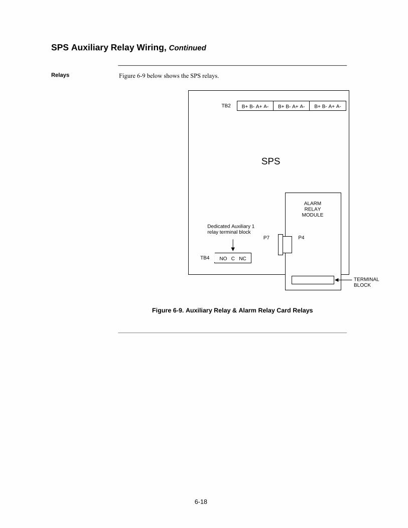
6-18
Figure 6-9 below shows the SPS relays.
Figure 6-9. Auxiliary Relay & Alarm Relay Card Relays
SPS Auxiliary Relay Wiring, Continued
Relays
B+ B- A+ A- B+ B- A+ A- B+ B- A+ A-TB2
SPS
Dedicated Auxiliary 1 relay terminal block
NO C NCTB4
TERMINAL BLOCK
ALARM RELAY
MODULE
P7 P4

7-1
xe "service port"
The 4100ES supports IDNet ports on several different slave cards. Each IDNet port provides a connection to a wiring loop of up to 250 addressable detectors and devices. These IDNet ports use Mapnet Protocol and communicate with existing Mapnet detectors/devices plus the new IDNet devices. The 4100ES slave modules with IDNet ports are:
4100-9848AU SPS System Power Supply 4100-3101AU IDNet card 4100-3107AU IDNet+ card
Refer to the page number listed in this table for information on a specific topic.
Topic See Page #
IDNet Port Characteristics 7-2
Wiring to IDNet Devices 7-3
Troubleshooting IDNet Faults 7-7
Chapter 7 IDNet Wiring Rules
Introduction
In this Chapter

7-2
There are three 4100ES slave modules with IDNet ports:
4100-9848AU SPS System Power Supply – this supports up to 250 devices in a single loop or string. The IDNet port is not isolated from the system 24V supply. The SPS is described in Chapter 6.
4100-3101AU IDNet card – this supports up to 250 devices in a single loop or string. The IDNet port is not isolated from the system 24V supply. The IDNet module is a 4x5” PDI card.
4100-3107AU IDNet+ card – this supports up to 246 devices in up to four loops or strings. Each loop or string is isolated from faults in the other loops or strings. The number of devices in each loop or string is arbitrary. The IDNet ports are electrically isolated from the system 24V supply. The IDNet+ module is an 8x5” PDI card, i.e., double width.
Mounting of PDI cards in equipment bays is described in Chapter 2. When purchased as spares, the IDNet and IDNet+ modules are supplied with comprehensive installation and configuration instructions.
Voltage output to IDNet devices is normally 30VDC.
Output is increased to 35 VDC when LEDs, piezos, or other outputs are activated, particularly in the alarm state.
The 30/35V supply for each IDNet port is rated at at least 350mA. Overcurrent protection is provided by a PTC.
Up to 250 IDNet devices are supported by each IDNet port. The IDNet+ slave uses four addresses internally for fault isolation, so only 246 addresses are available for external devices.
The IDNet module keeps track of which LEDs should be on at all times, and powers up to 20 at any given time.
Up to 43 coded piezo sounders are supported by each IDNet channel.
Continued on next page
IDNet Ports in 4100ES
Overview
IDNet Port Characteristics

7-3
Up to 250 IDNet slave devices, such as smoke detectors and manual call points, can be connected to the IDNet card using Class A (loop) or Class B (spur or string) wiring, with the following restrictions. Class A wiring allows the devices to communicate with the IDNet card even in the event of an open circuit somewhere in the loop. Class A wiring requires that two wires are routed from the IDNet card to each IDNet device, and then back again to the IDNet card. Under AS 1670.1 requirements, each group of up to 40 devices must be separated by a loop isolator. Class B wiring allows “T” tapping, and therefore requires less wiring distance per installation than Class A. Under AS 1670.1 requirements, no more than 40 devices may be connected with Class B wiring. See Appendix E for a list of compatible devices and their ratings.
Use ferrite beads on each pair of wires leaving the 4100ES cabinet. See Figure 7-1. See Appendix K for ordering part numbers.
Figure 7-1. Ferrite Bead Wiring
Shielded cable is recommended in electrically noisy environments.
IDNet cabling should not be run adjacent to other cabling, especially non-fire system cabling, such as mains.
The limiting factors on the length of the twin core cable connecting the IDNet devices to the IDNet card are cable capacitance (attenuates the superimposed coms signal) and resistance (causes voltage drop of the supply voltage and comms signals).
The maximum capacitance of 0.58uF core to core must also include the mutual capacitance of core to earth. Shielded cable has a much higher capacitance to earth than unshielded cable.
Rather than do voltage drop calculations, Figure 7-2 can be used to check that cable limits have not been reached. For a Class A (loop) circuit, cable distance refers to the full distance around the loop. For a Class B (spur) circuit, cable distance refers to the distance from the panel to the furthest end of the cable.
Sounder bases and 6 point I/O modules do not draw the alarm load from the loop, but are powered from separate 24V terminals.
Where devices such as sounder bases are wired from a 24V source (e.g. supplied by 24V AUX Power or a NAC), and are in more than one zone, the power cable must also be isolated between zones by a 4090-9117AU Power Isolator Module.
Continued on next page
Wiring to IDNet Devices
Overview
Guidelines
Wires go twice through (1 turn)
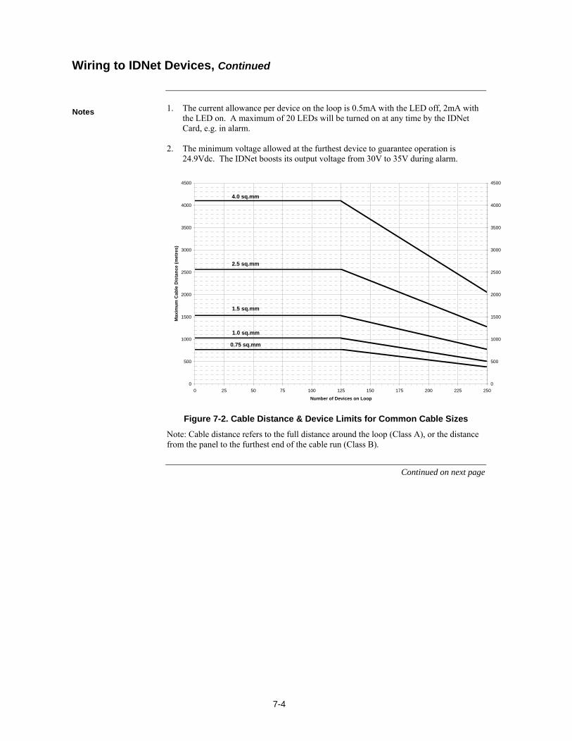
7-4
1. The current allowance per device on the loop is 0.5mA with the LED off, 2mA with the LED on. A maximum of 20 LEDs will be turned on at any time by the IDNet Card, e.g. in alarm. 2. The minimum voltage allowed at the furthest device to guarantee operation is 24.9Vdc. The IDNet boosts its output voltage from 30V to 35V during alarm.
0
500
1000
1500
2000
2500
3000
3500
4000
4500
0 25 50 75 100 125 150 175 200 225 250
Number of Devices on Loop
Ma
xim
um
Ca
ble
Dis
tan
ce (
me
tre
s)
0
500
1000
1500
2000
2500
3000
3500
4000
4500
0.75 sq.mm
1.0 sq.mm
1.5 sq.mm
2.5 sq.mm
4.0 sq.mm
Figure 7-2. Cable Distance & Device Limits for Common Cable Sizes
Note: Cable distance refers to the full distance around the loop (Class A), or the distance from the panel to the furthest end of the cable run (Class B).
Continued on next page
Wiring to IDNet Devices, Continued
Notes
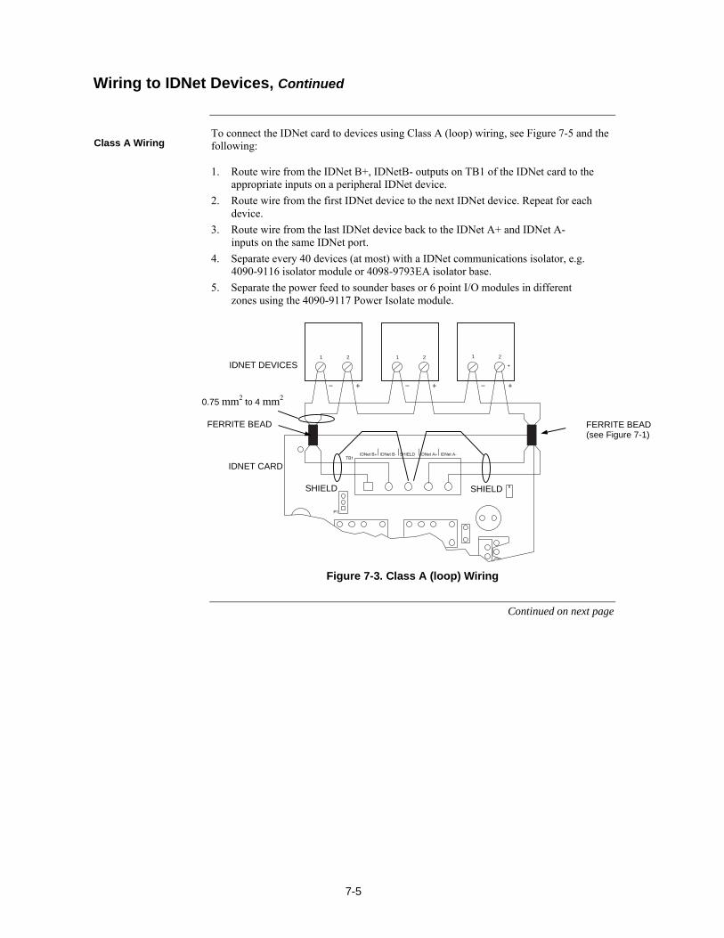
7-5
To connect the IDNet card to devices using Class A (loop) wiring, see Figure 7-5 and the following: 1. Route wire from the IDNet B+, IDNetB- outputs on TB1 of the IDNet card to the
appropriate inputs on a peripheral IDNet device.
2. Route wire from the first IDNet device to the next IDNet device. Repeat for each device.
3. Route wire from the last IDNet device back to the IDNet A+ and IDNet A- inputs on the same IDNet port.
4. Separate every 40 devices (at most) with a IDNet communications isolator, e.g. 4090-9116 isolator module or 4098-9793EA isolator base.
5. Separate the power feed to sounder bases or 6 point I/O modules in different zones using the 4090-9117 Power Isolate module.
+
1 21 2 1 2
Figure 7-3. Class A (loop) Wiring
Continued on next page
Wiring to IDNet Devices, Continued
Class A Wiring
IDNET CARD
IDNET DEVICES
0.75 mm2 to 4 mm2
SHIELD SHIELD
FERRITE BEAD
FERRITE BEAD (see Figure 7-1)
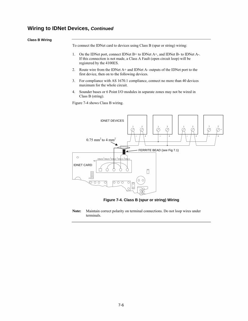
7-6
To connect the IDNet card to devices using Class B (spur or string) wiring: 1. On the IDNet port, connect IDNet B+ to IDNet A+, and IDNet B- to IDNet A-.
If this connection is not made, a Class A Fault (open circuit loop) will be registered by the 4100ES.
2. Route wire from the IDNet A+ and IDNet A- outputs of the IDNet port to the first device, then on to the following devices.
3. For compliance with AS 1670.1 compliance, connect no more than 40 devices maximum for the whole circuit.
4. Sounder bases or 6 Point I/O modules in separate zones may not be wired in Class B (string).
Figure 7-4 shows Class B wiring.
+
1 21 2 1 2 1 2
Figure 7-4. Class B (spur or string) Wiring
Note: Maintain correct polarity on terminal connections. Do not loop wires under terminals.
Class B Wiring
Wiring to IDNet Devices, Continued
IDNET CARD
IDNET DEVICES
0.75 mm2 to 4 mm2
FERRITE BEAD (see Fig 7.1)
7-7
This section describes the messages that may appear on the 4100 display when using the IDNet card. Fault messages appear in the headings on the left, and possible causes are listed in the text.
There is no output voltage from the IDNet power supply. Replace the IDNet card.
Appears if one or more extra devices (i.e., devices that have not been configured for the IDNet channel) are found on the ID-Net loops, or if a device is at an incorrect address. Only one message appears, regardless of the number of extra devices found. Viewing the fault log will reveal the extra device address.
There is an open circuit on the IDNet channel. After fixing the wiring fault, a hardware reset is required to reset the trouble.
Appears while the IDNet card is searching for earth faults on the IDNet line. When this message is displayed, the IDNet card cannot show any alarms or other statuses.
Appears when a short circuit is detected on the IDNet channel. This status clears automatically when the short circuit is removed.
Appears when devices have been configured, but none of the devices are communicating on the channel. This message does not appear if there are no configured devices on the IDNet channel.
Appears when a device is missing.
Appears when there is a faulty device or a noisy communications channel. Occurs during any of these conditions:
24 V is not present on TrueAlarm devices. TrueAlarm sensor bases with relay driver outputs are not properly supervised. Isolator devices are in isolation mode.
Troubleshooting IDNet Faults
Overview
IDNet Power Monitor Trouble
Extra Device
Class A Trouble
Earth Fault Search
Short Circuit
Channel Fail
No Answer
Bad Answer
Output Abnormal

7-8
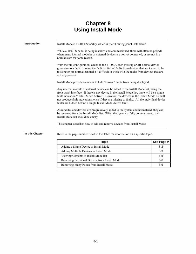
8-1
Install Mode is a 4100ES facility which is useful during panel installation. While a 4100ES panel is being installed and commissioned, there will often be periods when many internal modules or external devices are not yet connected, or are not in a normal state for some reason. With the full configuration loaded in the 4100ES, each missing or off-normal device gives rise to a fault. Having the fault list full of faults from devices that are known to be missing or off-normal can make it difficult to work with the faults from devices that are actually present. Install Mode provides a means to hide “known” faults from being displayed. Any internal module or external device can be added to the Install Mode list, using the front panel interface. If there is any device in the Install Mode list, there will be a single fault indication “Install Mode Active”. However, the devices in the Install Mode list will not produce fault indications, even if they are missing or faulty. All the individual device faults are hidden behind a single Install Mode Active fault. As modules and devices are progressively added to the system and normalised, they can be removed from the Install Mode list. When the system is fully commissioned, the Install Mode list should be empty. This chapter describes how to add and remove devices from Install Mode.
Refer to the page number listed in this table for information on a specific topic.
Topic See Page #
Adding a Single Device to Install Mode 8-2
Adding Multiple Devices to Install Mode 8-3
Viewing Contents of Install Mode list 8-5
Removing Individual Devices from Install Mode 8-6
Removing Many Points from Install Mode 8-6
Chapter 8 Using Install Mode
Introduction
In this Chapter
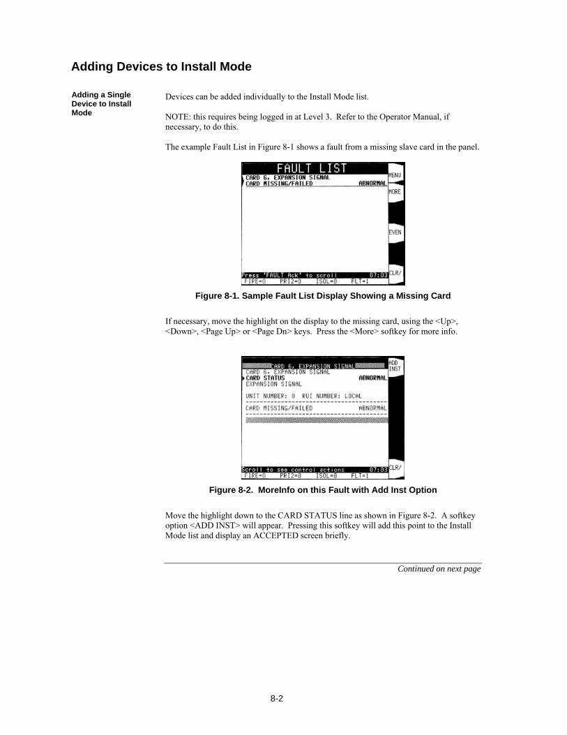
8-2
Devices can be added individually to the Install Mode list. NOTE: this requires being logged in at Level 3. Refer to the Operator Manual, if necessary, to do this. The example Fault List in Figure 8-1 shows a fault from a missing slave card in the panel.
Figure 8-1. Sample Fault List Display Showing a Missing Card
If necessary, move the highlight on the display to the missing card, using the <Up>, <Down>, <Page Up> or <Page Dn> keys. Press the <More> softkey for more info.
Figure 8-2. MoreInfo on this Fault with Add Inst Option
Move the highlight down to the CARD STATUS line as shown in Figure 8-2. A softkey option <ADD INST> will appear. Pressing this softkey will add this point to the Install Mode list and display an ACCEPTED screen briefly.
Continued on next page
Adding Devices to Install Mode
Adding a Single Device to Install Mode
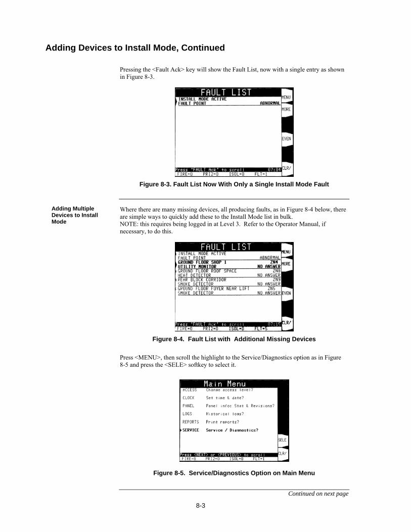
8-3
Pressing the <Fault Ack> key will show the Fault List, now with a single entry as shown in Figure 8-3.
Figure 8-3. Fault List Now With Only a Single Install Mode Fault
Where there are many missing devices, all producing faults, as in Figure 8-4 below, there are simple ways to quickly add these to the Install Mode list in bulk. NOTE: this requires being logged in at Level 3. Refer to the Operator Manual, if necessary, to do this.
Figure 8-4. Fault List with Additional Missing Devices
Press <MENU>, then scroll the highlight to the Service/Diagnostics option as in Figure 8-5 and press the <SELE> softkey to select it.
Figure 8-5. Service/Diagnostics Option on Main Menu
Continued on next page
Adding Devices to Install Mode, Continued
Adding Multiple Devices to Install Mode
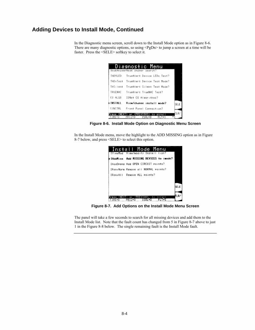
8-4
In the Diagnostic menu screen, scroll down to the Install Mode option as in Figure 8-6. There are many diagnostic options, so using <PgDn> to jump a screen at a time will be faster. Press the <SELE> softkey to select it.
Figure 8-6. Install Mode Option on Diagnostic Menu Screen
In the Install Mode menu, move the highlight to the ADD MISSING option as in Figure 8-7 below, and press <SELE> to select this option.
Figure 8-7. Add Options on the Install Mode Menu Screen
The panel will take a few seconds to search for all missing devices and add them to the Install Mode list. Note that the fault count has changed from 5 in Figure 8-7 above to just 1 in the Figure 8-8 below. The single remaining fault is the Install Mode fault.
Adding Devices to Install Mode, Continued
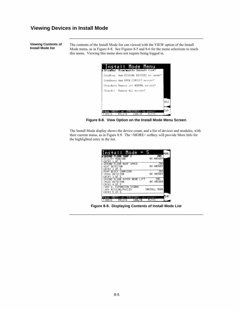
8-5
The contents of the Install Mode list can viewed with the VIEW option of the Install Mode menu, as in Figure 8-8. See Figures 8-5 and 8-6 for the menu selections to reach this menu. Viewing this menu does not require being logged in.
Figure 8-8. View Option on the Install Mode Menu Screen
The Install Mode display shows the device count, and a list of devices and modules, with their current status, as in Figure 8.9. The <MORE> softkey will provide More Info for the highlighted entry in the list.
Figure 8-9. Displaying Contents of Install Mode List
Viewing Devices in Install Mode
Viewing Contents of Install Mode list
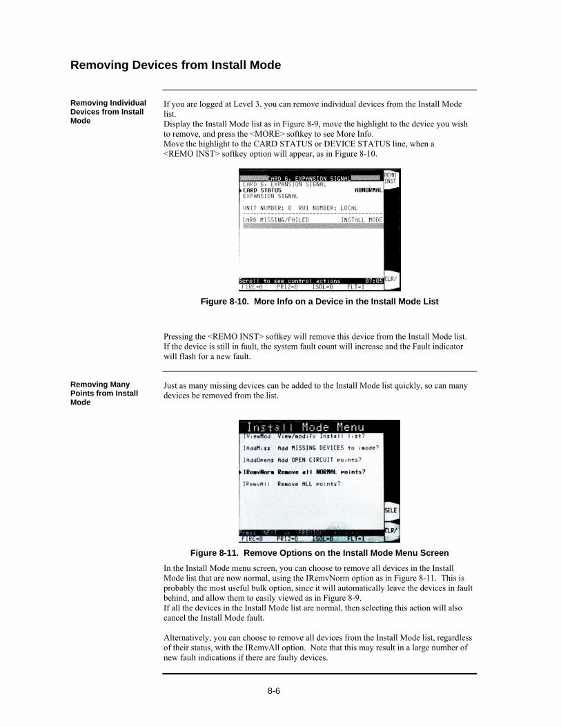
8-6
If you are logged at Level 3, you can remove individual devices from the Install Mode list. Display the Install Mode list as in Figure 8-9, move the highlight to the device you wish to remove, and press the <MORE> softkey to see More Info. Move the highlight to the CARD STATUS or DEVICE STATUS line, when a <REMO INST> softkey option will appear, as in Figure 8-10.
Figure 8-10. More Info on a Device in the Install Mode List
Pressing the <REMO INST> softkey will remove this device from the Install Mode list. If the device is still in fault, the system fault count will increase and the Fault indicator will flash for a new fault.
Just as many missing devices can be added to the Install Mode list quickly, so can many devices be removed from the list.
Figure 8-11. Remove Options on the Install Mode Menu Screen
In the Install Mode menu screen, you can choose to remove all devices in the Install Mode list that are now normal, using the IRemvNorm option as in Figure 8-11. This is probably the most useful bulk option, since it will automatically leave the devices in fault behind, and allow them to easily viewed as in Figure 8-9. If all the devices in the Install Mode list are normal, then selecting this action will also cancel the Install Mode fault. Alternatively, you can choose to remove all devices from the Install Mode list, regardless of their status, with the IRemvAll option. Note that this may result in a large number of new fault indications if there are faulty devices.
Removing Devices from Install Mode
Removing Individual Devices from Install Mode
Removing Many Points from Install Mode

9-1
The service port on the door with the Operator Interface enables the 4100ES to connect to PCs running important utilities, such as diagnostics, programming, CPU firmware downloading, and channel monitoring. The recommended connection method is using the Ethernet service port. However, a serial data connection can be used if the Ethernet option is not available for some reason. The ES Programmer supports both methods of connection.
Refer to the page number listed in this table for information on a specific topic.
Topic See Page #
Connection and Modes 9-2
Chapter 9 PC Software Connections
Introduction
In this Chapter
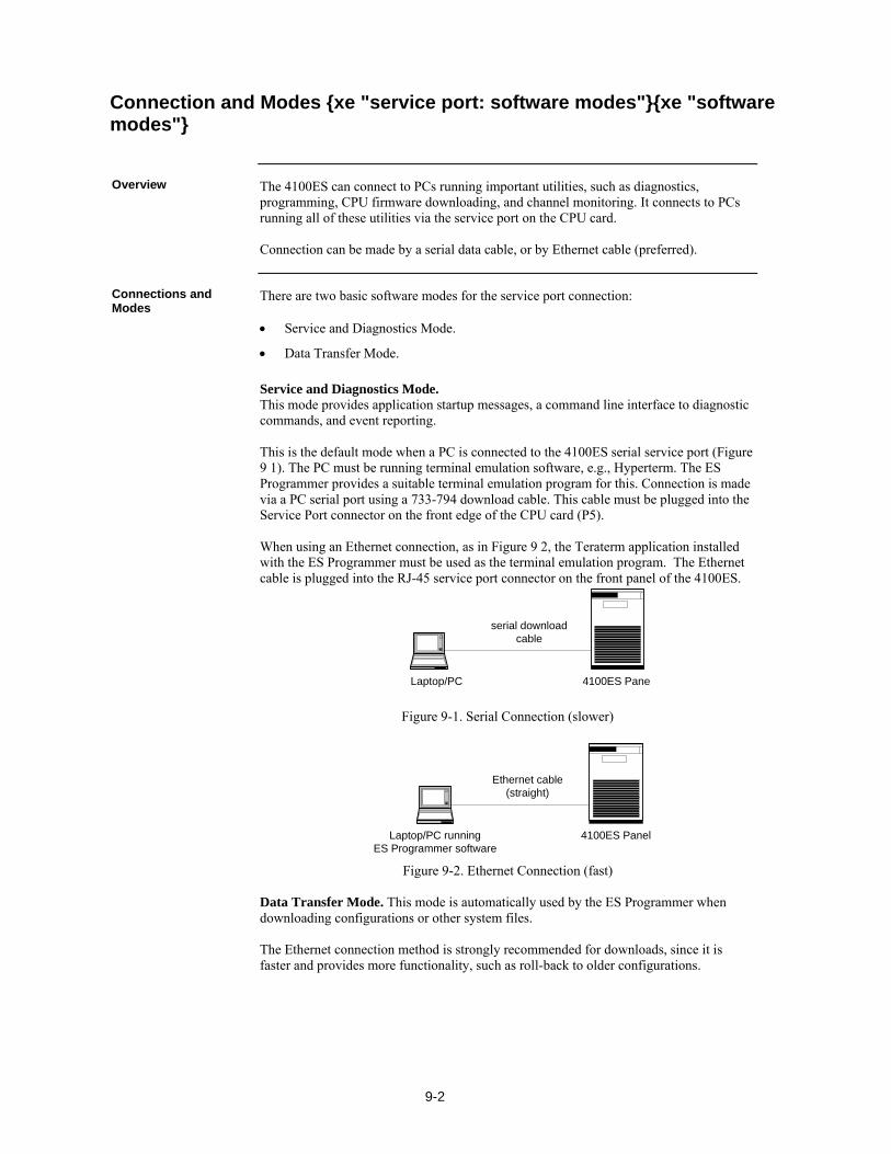
9-2
The 4100ES can connect to PCs running important utilities, such as diagnostics, programming, CPU firmware downloading, and channel monitoring. It connects to PCs running all of these utilities via the service port on the CPU card. Connection can be made by a serial data cable, or by Ethernet cable (preferred).
There are two basic software modes for the service port connection: Service and Diagnostics Mode.
Data Transfer Mode.
Service and Diagnostics Mode. This mode provides application startup messages, a command line interface to diagnostic commands, and event reporting. This is the default mode when a PC is connected to the 4100ES serial service port (Figure 9 1). The PC must be running terminal emulation software, e.g., Hyperterm. The ES Programmer provides a suitable terminal emulation program for this. Connection is made via a PC serial port using a 733-794 download cable. This cable must be plugged into the Service Port connector on the front edge of the CPU card (P5). When using an Ethernet connection, as in Figure 9 2, the Teraterm application installed with the ES Programmer must be used as the terminal emulation program. The Ethernet cable is plugged into the RJ-45 service port connector on the front panel of the 4100ES.
Laptop/PC 4100ES Panel
serial download cable
Figure 9-1. Serial Connection (slower)
Laptop/PC runningES Programmer software
4100ES Panel
Ethernet cable (straight)
Figure 9-2. Ethernet Connection (fast)
Data Transfer Mode. This mode is automatically used by the ES Programmer when downloading configurations or other system files. The Ethernet connection method is strongly recommended for downloads, since it is faster and provides more functionality, such as roll-back to older configurations.
Connection and Modes xe "service port: software modes"xe "software modes"
Overview
Connections and Modes
10-1
xe "service port"
This chapter provides detail on format and components that are specific to the Australian version 4100ES that complies with AS 4428.
Refer to the page number listed in this table for information on a specific topic.
Topic See Page #
Summary of Australian Version Specifics 10-2
Australian Panel Format 10-3
4100ES Fan Control Module 10-4
Brigade Interfaces 10-6
Chapter 10 Australian Version Specifics
Introduction
In this Chapter

10-2
The Australian fire alarm standards differ from those in the USA. Shipping costs from USA to Australia are significant, and the Australian market is small compared to the USA market. It is therefore necessary to: Have an Australian specific panel format that differs from the standard USA panel
format. Have some Australian specific components. Limit the number of system components available in the Australian version.
The 4100ES Operator Interface does not comply with the AS 4428.1 requirements for an FF (Firefighter Facility) that uses only an alphanumeric display for alarm zone status indication. The basic firmware of 4100ES does not accommodate zones as described in AS 4428.1. The standard SPS (System Power Supply) does not have the required charger and battery supervision and test facilities. Therefore the following are required for an Australian 4100ES: Use a different Operator Interface front label (overlay) and keypad with “Trouble”
changed to “Fault”, “Supervisory” changed to “Isolate”. This overlay is also smaller and has different text in the instructions on the bottom.
Use an Australian version of the message library with “Trouble” changed to “Fault”, “Supervisory” changed to “Isolate”.
Configure the programmable control keys and indications on the Operator Interface with the functions shown in Figure 2-3.
Fit 8 Switch/16 LED Red/Yellow modules such that there is one switch plus one red and one yellow LED per zone to give individual zone isolate and alarm indications.
Configure zone and battery test functionality in custom control. The custom control programming requirements are covered in Appendix B.
Use an Australian version of the SPS (with a modified PCB and firmware). Because of low quantity, only one format is available. Note that in a Brigade connected FIP, the SPS controls the Brigade Interface relays. If the CPU Card fails, or if the SPS CPU fails, the Fault (Trouble) relay turns on. This watchdog action provided by the SPS is a requirement.
Summary of Australian Version Specifics xe "service port: software modes"xe "software modes"
Overview
AS 4428 Requirements

10-3
Australian 4100ES panels are assembled in the Australian (Tyco) range of 19” rack cabinets. xe "service port: software modes"xe "software modes"
Some further specific differences follow: Only the Expansion Bay is used, with the Controller CPU and Motherboard mounted
in the right hand side of the first one. The standard US Controller Bay is not used.
The InfoAlarm Operator Interface is fitted to an Australian specific 8U hinged bracket mounted in front of the SPS.
The zone displays and Fan Controls are mounted on a 7U hinged door.
Australian specific bay mounting brackets and trims are used. This includes the standard range of 19” rack mount panels and brackets.
Only one version of SPS is available. This mounts on a specific bracket and also to an expansion bay, and is unique to Australia.
4100-3101 IDNet and 4100-3107 IDNet+ cards are used but require specific Australia slave software.
Two of the addressable modules are modified specifically for AS 4428, i.e. 4090-9117AU Addressable Power Isolations, and the 4090-9120AU 6 Point I/O.
Other cards / modules not used in Australia include the large range of Evacuation products and some modems.
xe "service port: software modes"xe "software modes"
Standard 4100 motherboards and cards fit in a 4100ES bay. The following 4100A items however, do not fit: Older 4100 Switch/LED display modules.
The range of Australian brackets that mount to the front of a 4100 bay. This includes
some EWIS products, Brigade interface brackets, T-GEN bracket, and printer.
Note that although 4100 cards fitted to motherboards, and the bay mounting brackets, can be fitted in directly behind Switch/LED modules, they cannot be fitted behind the 64/64 Switch/LED Controller mounted to the inside of the bay door. This is typically mounted behind the LED/Switch Modules fitted to the 1st and 2nd positions from the left.
Australian Panel Format xe "service port: software modes"xe "software modes"
Overview
Australian / USA Differences
4100ES/4100A Differences

10-4
ME0456 is a 4100ES style Switch/LED display module specifically designed for fan control. It complies with the requirements of AS 1668.1, 1998. It has rotary switches and LEDs for 4 fans. In order to accommodate the required rotary switches, the front plate is joggled forward so that it protrudes through the trim. xe "service port: software modes"xe "software modes"
The Fan Control switch positions of ON, AUTO and OFF, as per the standard, are permanently marked on the faceplate label. The labelling of the LEDs, ON, FLT, and OFF is marked on the removable fan name label card, LB0605, supplied with the module. The card may be reversed and different LED labelling used, e.g., as required for damper controls. The name area accommodates 3 rows of 6 letters at 5mm text height. A “soft” version of this label is available on the Fireplace website (https://www.tycosafetyproducts-anz.com) as LB0605. This template allows entry of the fan name on a PC for local printing. LED names may also be revised.
The Fan Control module mounts to the frame of the 4100ES Expansion bay door, from the front, by the studs on the module with the nuts and washers provided. Connection from “Out” of the adjacent Switch/LED module (or 64/64 Controller if it is the first module on that Controller) to “In” on the module is by the flat flexible cable provided (SX0039). xe "service port: software modes"xe "software modes"
The Module is programmed as a standard 4100-1282 8 Switch/16 LED module. Up to 4 can be driven by one 64/64 Switch/LED Controller. Each fan control with one rotary switch uses two of the 8 “switches”, and 3 of the 16 LEDs of an 8 Switch/16 LED module as per Table 9-1. The other 4 LEDs are not fitted so must not be programmed.
Table 10-1. Switch/LED Format
Fan Control Switches LEDs ON FLT OFF 1 SW1, SW2 LD1 LD2 LD3 2 SW3, SW4 LD5 LD6 LD7 3 SW5, SW6 LD9 LD10 LD11 4 SW7, SW8 LD13 LD14 LD15
The switch functions for Fan Control 1 are shown in Table 9-2. The state with both switches closed is not physically achievable.
Table 10-2. Switch Status
SW1 SW2 Control Status Closed (up) Open (centre) On
Open (centre) Closed (up) Off Open (centre) Open (centre) Auto
Continued on next page
4100ES Fan Control Module xe "service port: software modes"xe "software modes"
Overview
Labeling
Mounting & Connection
Programming
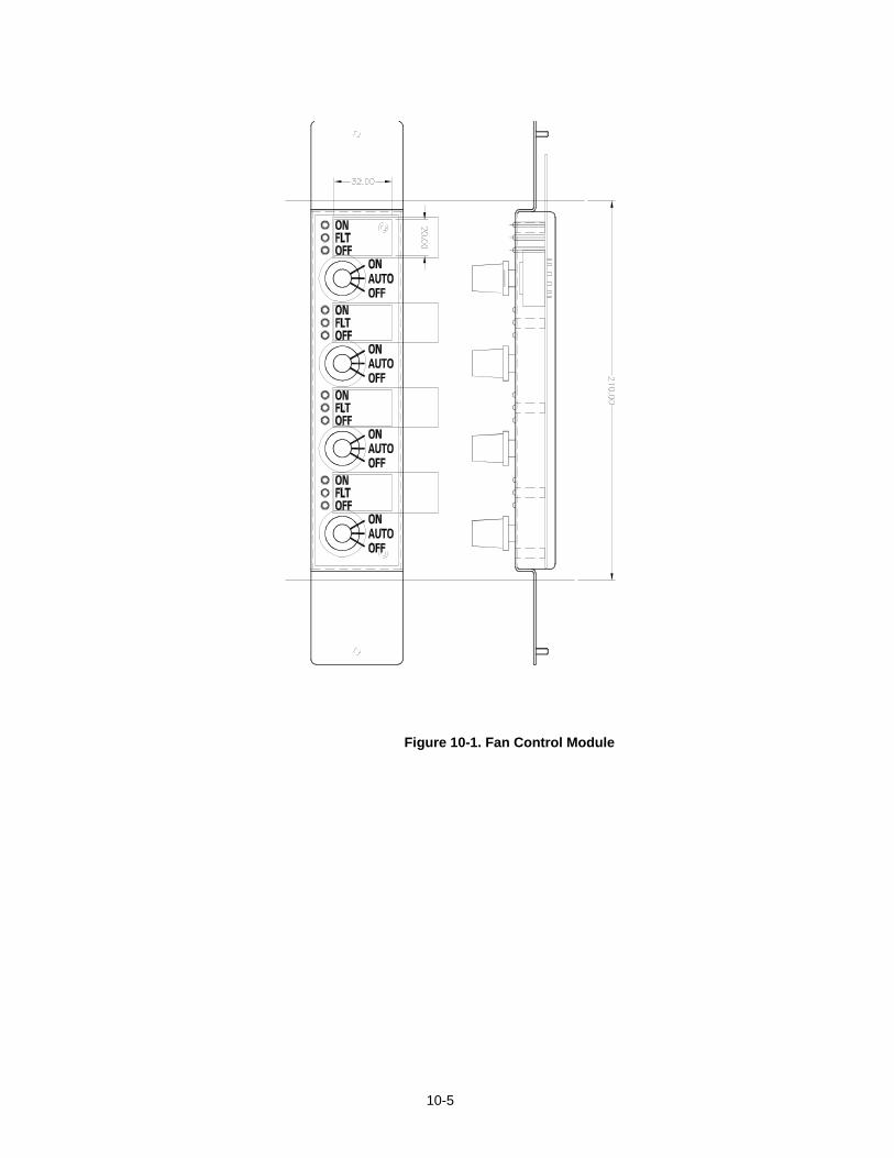
10-5
Figure 10-1. Fan Control Module
10-6
xe "service port: software modes"xe "software modes"
The Alarm Relay Card is typically used to provide a Brigade Interface. The defxe "service port: software modes"xe "software modes"ault configuration is for the three relays to operate on Fault (Trouble), Isolate (Supervisory) and Alarm, respectively. The connection drawings for the Centaur ASE, Western Australia AIU and Queensland PPU are included in the appendix. xe "service port: software modes"xe "software modes"
These relays are normally de-energisedxe "service port: software modes"xe "software modes" and energise on the respective status. They have voltage-free contacts that are connected to two terminals and can be configured as normally open or normally closed by the positioning of links. Refer to Chapter 5 for details. If a normally energized relay is required to provide activation on complete loss of system power (Standby), the Aux Relay on the SPS can be programmed as normally on and its contacts connected in series/parallel with the contacts of the Fault (Trouble) relay as is applicable, i.e., series for normally closed, parallel for normally open. Where the Brigade interface is powered from the system power and monitored by the central station, this is not typically required. Note that the Aux relay is programmed as normally energised, de-energising on Fault cannot be used to replace the Fault relay on the Alarm Relay Card as the latter is link connected to a hardware signal of “SPS CPU Fault”. xe "service port: software modes"xe "software modes"
Standard rack mounting, 3U, Brigade Interface brackets are available as follows. FZ9028 includes the wiring loom. KT0199 requires KT0207 to provide the wiring loom with the encapsulated Interface (FP0740). Standard rack mounting, 4U, Brigade Interface brackets are available in black finish. FP0935 (Centaur ASE) or FP0937 (WA/Cube ASE). Both these kits include mounting hardware, Centaur ASE FAS unit, and wiring to supply power to the ASE from the SPS. Connection for the Centaur ASE is shown in drawing 1976-174 Sheet 1. Connections for the Cube ASE and WA ASE are shown in drawing 1922-96. For the WA ASE, the links on the Alarm Relay Card are fitted for normally open contacts. For the Centaur ASE, the links are fitted for normally closed contacts.
Brigade Interfaces
Overview
Format
Applications

11-1
xe "service port"
When a branch designs a system and orders a 4100ES panel, a “Configuration Sheet” is prepared. The factory builds the panel to the configuration sheet. This includes fitting, connecting and configuring cards and modules. The factory programs and tests the panel to the configured sheet. The CPU Card and any 4100 style (legacy) cards that are fitted to motherboards are then removed and packaged with the panel for shipping. When the panel arrives on site the installer must unpack and check the panel, mount the cabinet, refit any packaged cards, and check the configuration before applying power. A registered electrician must connect the mains. The panel should then be powered up and checked for correct operation. With the mains turned off and the batteries disconnected, the field wiring is checked and connected to the field terminals on the various cards. The panel should then be powered up and re-programmed to accommodate all the connected field devices. Faults in the field wiring, misaddressed detectors / devices, mismatched detectors / devices will be displayed on the LCD. These should be cleared one at a time and then the system (panel plus connected devices) should be commissioned.
Refer to the page number listed in this table for information on a specific topic.
Topic See Page #
Installation Checklist 11-2
Alignment & Adjustment 11-3
Power Up & Placing into Operation 11-4
Maintenance 11-4
Chapter 11 Installation Checklist, Commissioning & Maintenance
Introduction
In this Chapter
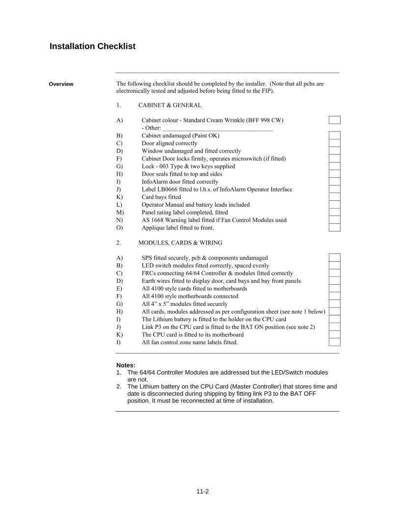
11-2
The following checklist should be completed by the installer. (Note that all pcbs are electronically tested and adjusted before being fitted to the FIP). 1. CABINET & GENERAL A) Cabinet colour - Standard Cream Wrinkle (BFF 998 CW) - Other: ____________________________________ B) Cabinet undamaged (Paint OK) C) Door aligned correctly D) Window undamaged and fitted correctly F) Cabinet Door locks firmly, operates microswitch (if fitted) G) Lock - 003 Type & two keys supplied H) Door seals fitted to top and sides I) InfoAlarm door fitted correctly J) Label LB0666 fitted to l.h.s. of InfoAlarm Operator Interface K) Card bays fitted L) Operator Manual and battery leads included M) Panel rating label completed, fitted N) AS 1668 Warning label fitted if Fan Control Modules used O) Applique label fitted to front. 2. MODULES, CARDS & WIRING
A) SPS fitted securely, pcb & components undamaged B) LED switch modules fitted correctly, spaced evenly C) FRCs connecting 64/64 Controller & modules fitted correctly D) Earth wires fitted to display door, card bays and bay front panels E) All 4100 style cards fitted to motherboards F) All 4100 style motherboards connected G) All 4” x 5” modules fitted securely H) All cards, modules addressed as per configuration sheet (see note 1 below) I) The Lithium battery is fitted to the holder on the CPU card J) Link P3 on the CPU card is fitted to the BAT ON position (see note 2) K) The CPU card is fitted to its motherboard I) All fan control zone name labels fitted.
Notes: 1. The 64/64 Controller Modules are addressed but the LED/Switch modules
are not. 2. The Lithium battery on the CPU Card (Master Controller) that stores time and
date is disconnected during shipping by fitting link P3 to the BAT OFF position. It must be reconnected at time of installation.
Installation Checklist
Overview

11-3
All the 4100ES cards and modules are tested and aligned in the factory before being supplied to the customer or fitted to a FIP. The only field adjustment that may be necessary is to set the battery charger voltage. This has been set and should not need re-adjusting. R341 Battery Charger Voltage Should the battery charger voltage need adjusting, the method is as follows: 1. Run the system with the batteries connected and the door closed for at least 30
minutes to allow components to stabilise. 2. Calculate the required no-load battery charging voltage by taking 27.3V for
20C and subtracting approximately 0.1V for every 3C above 20C, or adding approximately 0.1V for every 3C below 20C.
3. With the system not in Alarm, disconnect the batteries. 4. Measure the voltage at the battery terminals and adjust to the voltage calculated
in Step 2 by turning pot R341. 5. Re-connect the batteries.
Alignment & Adjustment
Overview
11-4
To place the 4100ES FIP into operation, perform the following steps: STEP 1 Ensure that the Mains Isolate Switch is OFF. STEP 2 Ensure that 240 VAC is connected to the panel from the mains distribution
switchboard. STEP 3 Ensure that the Lithium battery is fitted to the battery holder on the CPU card, and link P3 is fitted to the BAT ON position. Turn the Mains Switch ON. STEP 4 Check that the green "MAINS ON" LED indicator on the InfoAlarm user interface is on. The Controller performs tests on its memory, electronics, and the LCD. STEP 5 Check that the buzzer sounds and the LCD displays “CPU Serial Number”. STEP 6 Check that the LCD has good visibility. STEP 7 Install and connect the batteries. Take care not to short the battery leads or connect in reverse polarity when connecting. STEP 8 Press the Lamp Test key on the Operator I/F and check that all LEDs turn on, and the LCD shows all black squares. STEP 9 Clear all faults one at a time.
A full commissioning test should be carried out as per AS 1670.1. Refer to the appendix in this manual for detail on checking wiring, and earth fault detection. Refer to the Operator’s Manual LT0351 for detail of the walk test that may be used for verifying correct detector operation.
The 4100ES system must be kept free from faults and tested on a regular basis to verify that it is operating correctly. The tests required by the standard AS 1851 Maintenance of Fire Protection Equipment are detailed in the 4100ES InfoAlarm Operator’s Manual, LT0568. The Operator’s manual also provides detail of report printing and performing tests that are useful for checking the system.
Power Up & Placing into Operation
Maintenance
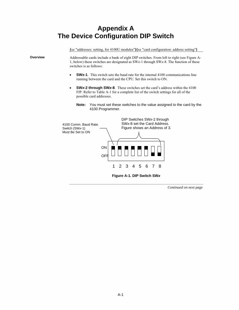
A-1
xe "addresses: setting, for 4100U modules"xe "card configuration: address setting"
Addressable cards include a bank of eight DIP switches. From left to right (see Figure A-1, below) these switches are designated as SWx-1 through SWx-8. The function of these switches is as follows: SWx-1. This switch sets the baud rate for the internal 4100 communications line
running between the card and the CPU. Set this switch to ON. SWx-2 through SWx-8. These switches set the card’s address within the 4100
FIP. Refer to Table A-1 for a complete list of the switch settings for all of the possible card addresses.
Note: You must set these switches to the value assigned to the card by the
4100 Programmer.
1 8 7 6 5 4 3 2
Figure A-1. DIP Switch SWx
Continued on next page
Appendix A The Device Configuration DIP Switch
Overview
ON
OFF
DIP Switches SWx-2 through SWx-8 set the Card Address. Figure shows an Address of 3.
4100 Comm. Baud Rate. Switch (SWx-1) Must Be Set to ON
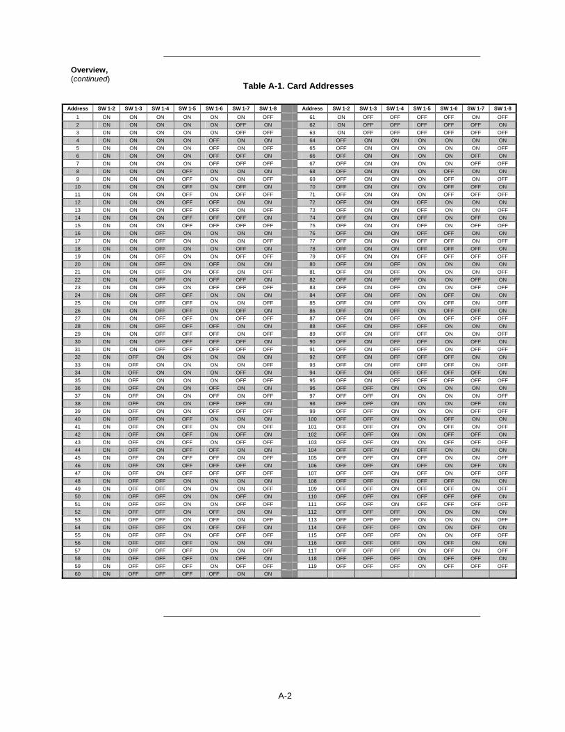
A-2
Table A-1. Card Addresses
Overview, (continued)
Address SW 1-2 SW 1-3 SW 1-4 SW 1-5 SW 1-6 SW 1-7 SW 1-8 Address SW 1-2 SW 1-3 SW 1-4 SW 1-5 SW 1-6 SW 1-7 SW 1-8
1 ON ON ON ON ON ON OFF 61 ON OFF OFF OFF OFF ON OFF
2 ON ON ON ON ON OFF ON 62 ON OFF OFF OFF OFF OFF ON
3 ON ON ON ON ON OFF OFF 63 ON OFF OFF OFF OFF OFF OFF
4 ON ON ON ON OFF ON ON 64 OFF ON ON ON ON ON ON
5 ON ON ON ON OFF ON OFF 65 OFF ON ON ON ON ON OFF
6 ON ON ON ON OFF OFF ON 66 OFF ON ON ON ON OFF ON
7 ON ON ON ON OFF OFF OFF 67 OFF ON ON ON ON OFF OFF
8 ON ON ON OFF ON ON ON 68 OFF ON ON ON OFF ON ON
9 ON ON ON OFF ON ON OFF 69 OFF ON ON ON OFF ON OFF
10 ON ON ON OFF ON OFF ON 70 OFF ON ON ON OFF OFF ON
11 ON ON ON OFF ON OFF OFF 71 OFF ON ON ON OFF OFF OFF
12 ON ON ON OFF OFF ON ON 72 OFF ON ON OFF ON ON ON
13 ON ON ON OFF OFF ON OFF 73 OFF ON ON OFF ON ON OFF
14 ON ON ON OFF OFF OFF ON 74 OFF ON ON OFF ON OFF ON
15 ON ON ON OFF OFF OFF OFF 75 OFF ON ON OFF ON OFF OFF
16 ON ON OFF ON ON ON ON 76 OFF ON ON OFF OFF ON ON
17 ON ON OFF ON ON ON OFF 77 OFF ON ON OFF OFF ON OFF
18 ON ON OFF ON ON OFF ON 78 OFF ON ON OFF OFF OFF ON
19 ON ON OFF ON ON OFF OFF 79 OFF ON ON OFF OFF OFF OFF
20 ON ON OFF ON OFF ON ON 80 OFF ON OFF ON ON ON ON
21 ON ON OFF ON OFF ON OFF 81 OFF ON OFF ON ON ON OFF
22 ON ON OFF ON OFF OFF ON 82 OFF ON OFF ON ON OFF ON
23 ON ON OFF ON OFF OFF OFF 83 OFF ON OFF ON ON OFF OFF
24 ON ON OFF OFF ON ON ON 84 OFF ON OFF ON OFF ON ON
25 ON ON OFF OFF ON ON OFF 85 OFF ON OFF ON OFF ON OFF
26 ON ON OFF OFF ON OFF ON 86 OFF ON OFF ON OFF OFF ON
27 ON ON OFF OFF ON OFF OFF 87 OFF ON OFF ON OFF OFF OFF
28 ON ON OFF OFF OFF ON ON 88 OFF ON OFF OFF ON ON ON
29 ON ON OFF OFF OFF ON OFF 89 OFF ON OFF OFF ON ON OFF
30 ON ON OFF OFF OFF OFF ON 90 OFF ON OFF OFF ON OFF ON
31 ON ON OFF OFF OFF OFF OFF 91 OFF ON OFF OFF ON OFF OFF
32 ON OFF ON ON ON ON ON 92 OFF ON OFF OFF OFF ON ON
33 ON OFF ON ON ON ON OFF 93 OFF ON OFF OFF OFF ON OFF
34 ON OFF ON ON ON OFF ON 94 OFF ON OFF OFF OFF OFF ON
35 ON OFF ON ON ON OFF OFF 95 OFF ON OFF OFF OFF OFF OFF
36 ON OFF ON ON OFF ON ON 96 OFF OFF ON ON ON ON ON
37 ON OFF ON ON OFF ON OFF 97 OFF OFF ON ON ON ON OFF
38 ON OFF ON ON OFF OFF ON 98 OFF OFF ON ON ON OFF ON
39 ON OFF ON ON OFF OFF OFF 99 OFF OFF ON ON ON OFF OFF
40 ON OFF ON OFF ON ON ON 100 OFF OFF ON ON OFF ON ON
41 ON OFF ON OFF ON ON OFF 101 OFF OFF ON ON OFF ON OFF
42 ON OFF ON OFF ON OFF ON 102 OFF OFF ON ON OFF OFF ON
43 ON OFF ON OFF ON OFF OFF 103 OFF OFF ON ON OFF OFF OFF
44 ON OFF ON OFF OFF ON ON 104 OFF OFF ON OFF ON ON ON
45 ON OFF ON OFF OFF ON OFF 105 OFF OFF ON OFF ON ON OFF
46 ON OFF ON OFF OFF OFF ON 106 OFF OFF ON OFF ON OFF ON
47 ON OFF ON OFF OFF OFF OFF 107 OFF OFF ON OFF ON OFF OFF
48 ON OFF OFF ON ON ON ON 108 OFF OFF ON OFF OFF ON ON
49 ON OFF OFF ON ON ON OFF 109 OFF OFF ON OFF OFF ON OFF
50 ON OFF OFF ON ON OFF ON 110 OFF OFF ON OFF OFF OFF ON
51 ON OFF OFF ON ON OFF OFF 111 OFF OFF ON OFF OFF OFF OFF
52 ON OFF OFF ON OFF ON ON 112 OFF OFF OFF ON ON ON ON
53 ON OFF OFF ON OFF ON OFF 113 OFF OFF OFF ON ON ON OFF
54 ON OFF OFF ON OFF OFF ON 114 OFF OFF OFF ON ON OFF ON
55 ON OFF OFF ON OFF OFF OFF 115 OFF OFF OFF ON ON OFF OFF
56 ON OFF OFF OFF ON ON ON 116 OFF OFF OFF ON OFF ON ON
57 ON OFF OFF OFF ON ON OFF 117 OFF OFF OFF ON OFF ON OFF
58 ON OFF OFF OFF ON OFF ON 118 OFF OFF OFF ON OFF OFF ON
59 ON OFF OFF OFF ON OFF OFF 119 OFF OFF OFF ON OFF OFF OFF
60 ON OFF OFF OFF OFF ON ON

B-1
xe "ULC programming requirements"
This appendix identifies the programming that is required to comply with AS 4428. It does not provide equations or detail of programming. The separate 4100ES Programming Manual (LT0400) tells how to use the PC-based 4100ES Programmer.
Refer to the page number listed in this table for information on a specific topic.
Topic See Page #
Required Features B-1
The following is a list of functions that must be programmed under custom control. Functionality must comply with AS 4428.1, and be as described in the InfoAlarm Operator’s Manual LT0568. Individual zone alarm indication, flashing until isolated, steady when isolated.
Common Zone Alarm indication, flashing when any unisolated zone is in alarm,
steady when all zones in alarm are isolated.
Individual zone isolate pushbutton and indication.
Zone Alarm Test pushbutton and indication.
Zone Fault Test pushbutton and indication.
Warning System Isolate pushbutton and indication.
Ancillary Control Function and Isolate pushbutton and indication as required.
Weekly 1 hour battery test.
Fault indication after 8 hours of isolate. The panel format is different to that on the programmer because the CPU card is fitted
on the RHS of the first expansion bay, and extra cards may be fitted to the left of it.
The US options for power supply and AVF are selected, not the Canadian ones.
Features that do not comply with AS 4428 must not be enabled, e.g., Alarm cut-out times.
Features that are statutory in AS 4428 must not be pass-code protected, e.g., zone isolate, zone test (Fault and Alarm).
Appendix B Programming Requirements
Introduction
In this Chapter
Required Features
Notes

B-2

C-1
xe "wiring: troubleshooting"xe "troubleshooting: wiring"xe "volt-Ohm meter usage"
This appendix contains instructions on how to use a volt/ohm meter to check field wiring to the 4100ES.
When using the volt/ohm meter to check each circuit, make sure to adhere to the notes and instructions below. Notes:
Ensure that no power is applied to the 4100ES fire alarm panel and that all internal panel wiring is properly connected (terminal blocks, LED/switch module ribbon cables, etc).
Use the earth stud in the control panel as the earth connection for all measurements to ground.
Disconnect the wires for each circuit from the 4100ES terminals before testing it.
Measuring resistances between 4100ES terminals or to ground will give meaningless results.
Use the volt/ohm meter as described in the steps below to check each circuit type:
1. At the 4100ES panel, disconnect the wires for each circuit from the terminals before testing it. If it is a Class A (loop) type of circuit, e.g., IDNet loop, ensure that both ends of the loop are disconnected from the 4100ES.
2. Check each circuit for extraneous voltage by setting the volt/ohm meter to a 300VAC range. Place the meter probes so that the black probe is on the “-” wire and the red probe is on the “+” wire. Meter readings must show less than 1V.
3. Set the volt/ohm meter to a 60VDC range and repeat step 2. The meter must read less than 0.5V.
4. Set the volt/ohm meter to OHMS and place the meter probes as described in step 2. Check the circuits using the resistance measurements in Table D-1. Locate and correct any abnormal conditions at this time. Note: If the reading indicates an open circuit in a detector circuit, make sure the smoke detector heads are properly mounted and seated. The circuit may also be open if smoke detector power is not present, and if separately powered 4-wire devices are used.
5. Repeat steps 1-4 for all field wiring, to verify that each circuit is free of grounds and extraneous voltages.
Continued on next page
Appendix C Checking System Wiring
Overview
Using the Volt/ Ohm Meter
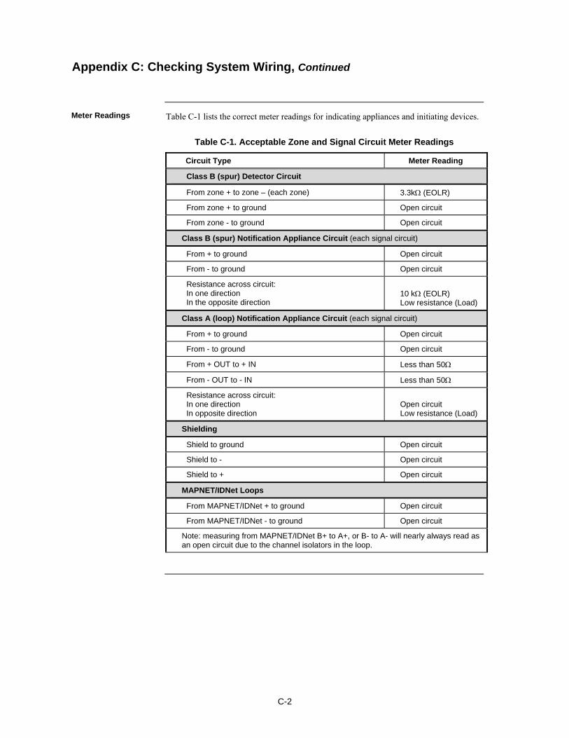
C-2
Table C-1 lists the correct meter readings for indicating appliances and initiating devices.
Table C-1. Acceptable Zone and Signal Circuit Meter Readings
Circuit Type Meter Reading
Class B (spur) Detector Circuit
From zone + to zone – (each zone) 3.3k (EOLR)
From zone + to ground Open circuit
From zone - to ground Open circuit
Class B (spur) Notification Appliance Circuit (each signal circuit)
From + to ground Open circuit
From - to ground Open circuit
Resistance across circuit: In one direction In the opposite direction
10 k (EOLR) Low resistance (Load)
Class A (loop) Notification Appliance Circuit (each signal circuit)
From + to ground Open circuit
From - to ground Open circuit
From + OUT to + IN Less than 50
From - OUT to - IN Less than 50
Resistance across circuit: In one direction In opposite direction
Open circuit Low resistance (Load)
Shielding
Shield to ground Open circuit
Shield to - Open circuit
Shield to + Open circuit
MAPNET/IDNet Loops
From MAPNET/IDNet + to ground Open circuit
From MAPNET/IDNet - to ground Open circuit
Note: measuring from MAPNET/IDNet B+ to A+, or B- to A- will nearly always read as an open circuit due to the channel isolators in the loop.
Appendix C: Checking System Wiring, Continued
Meter Readings

D-1
xe "wiring: Earth Fault Search"xe "Earth Fault Search"
This appendix contains instructions on how to use the Earth Fault Search feature of the 4100ES diagnostics menus. Earth Fault Search is a diagnostic search of external field wiring that assists in locating circuits with earth faults. An earth fault occurs when an electrical circuit is shorted to ground. Although most circuits operate with a single earth fault, multiple earth faults can disable communications. Because of this, earth faults must be located and repaired. Earth Fault Search is conducted by the FIP. The diagnostic may be activated using either the front panel interface or the Computer Port Protocol (CPP), via a service port. The 4100ES supports two types of Earth Fault Searches:
Location Search. Searches all circuits at a location, such as a transponder or the main panel. For the purposes of Earth Fault Searching,
- A location is composed of a group of slaves connected to each other via 4100 Comm (local RUI).
- The main panel is defined as all slaves local to the Master CPU.
- A transponder denotes all slaves associated with a single Transponder Interface Card (TIC)/Local Mode TIC slave.
IDNet Channel Search. Selectively enables channel isolators and repeaters to detect which segment of the channel wiring has a fault.
- Earth faults are detected by one of the following:
- A single designated power supply at a location. The power supply that detects the fault is designated via a jumper setting on the power supply slave. For any given location, only one power supply should detect earth faults.
- Each 4009 IDNet NAC Extender on an IDNet channel.
Appendix D Earth Fault Detection
Overview

D-2
Review the guidelines below before initiating an Earth Fault Search.
The Detect Earth Fault jumper must be installed at each SPS for earth fault detection to occur.
Only one power supply per location is configured to detect earth faults.
For more reliable earth fault searching:
- Use IDNet channel isolators to isolate channel faults to a specific segment of channel wiring.
- Set IDNet channel isolator addresses to the lowest IDNet device addresses, increasing with communication distance from the IDNet card.
If an earth fault is suspected on the IDNet channel with multiple isolators, start an IDNet Channel Search before doing a Location Search. If the Location Search is done first, it may not yield the correct location (this is a by-product of the extended amount of time required for the IDNet channel to initialize during a Location Search). Note: The 4009 IDNet NAC Extender has a common ground fault trouble that reports to the panel without running the Earth Fault Search.
Earth Fault Search detects only one fault at a time. Multiple faults require fixing the first fault and then repeating the search.
The 4100ES panel suspends normal operation for the duration of the Earth Fault Search.
Location Earth Fault Searches optionally allow exclusion of auxiliary power circuits from the search, so that modules connected to the 24 V auxiliary outputs can remain in operation during the search.
The option to exclude auxiliary power circuits does not apply to IDNet devices, because the entire IDNet communication channel is isolated during each search.
During the search, all related troubles are suppressed and a single trouble pseudo-point is activated (P438).
At the completion of the search, all slaves are restarted and normal panel operation resumes.
Earth Fault Search is supported only by new 4100ES modules. 4100 Legacy (slot format) modules are not supported, with the following exceptions:
- MAPNET channel isolation during location search
IMPORTANT: The fire panel cannot provide fire protection during an Earth Fault Search.
General Guidelines

D-3
This section describes how to conduct an Earth Fault Search, from selecting the appropriate access code to correcting the fault.
The panel must be at the appropriate access level in order to run diagnostics. If necessary, refer to the InfoAlarm Operator Manual supplied with the 4100ES, for the detail of how to log in at a higher level than 1. You can now open the diagnostic menu as described in the next topic.
To start an Earth Fault Search, open the Main Menu on the InfoAlarm. Select the Service/Diagnostics menu.
Select Earth Fault search in the diagnostics menu.
Continued on next page
Earth Fault Searching from the Front Panel
Overview
Access Level Selection
Starting the Earth Fault Search

D-4
The search types are described below.
If you select the Location Search menu item, a list of searchable cards is presented. Use the Next and Previous buttons to scroll through the list, if necessary.
Having selected a power supply to search, the Aux Power Select option comes up.
If you exclude the auxiliary power circuit from the search, that circuit will continue to operate normally. Continued on next page
Earth Fault Searching from the Front Panel, Continued
Starting the Earth Fault Search, Continued
Location Search

D-5
Now you are prompted to start the search.
NOTE: The FIP suspends normal operation for the duration of the search.
Press the Enter button to start the search.
Skip ahead to the "Completing the Search" topic.
If you select the IDNet Channel Search menu item, a list of available IDNet channels to search is displayed.
Use the Next and Previous buttons to scroll through the list if necessary. Press SELECT or OK to select the IDNet channel to search. Now you are prompted to start the search. NOTE: The FIP suspends normal operation for the duration of the search. Press the Enter button to start the search. Skip ahead to the "Completing the Search" topic.
Earth Fault Searching from the Front Panel, Continued
IDNet Channel Search

D-6
This option simply displays the last Earth Fault Search result. If there has been no search since the last system startup, or if the last search was aborted, the panel displays "RESULT NOT AVAILABLE."
When a Location or IDNet Channel Search completes, all of the following occurs:
All slaves automatically reset.
The FIP turns off the Earth Fault Search trouble pseudo-point.
The panel displays the specific fault information.
The panel can return only one Earth Fault Search result at a time. If another fault exists, it can be found only via diagnostics after the first fault is cleared. Faults will continue to appear, one by one, until each one has been found and corrected. IMPORTANT: Once you have been directed to an earth ground fault and corrected it, it is recommended that you restart the system (warm- or cold-start). Refer to the InfoAlarm Operator Manual for details of how to do this.
Earth Fault Searching from the Front Panel, Continued
Last Search Result
Completing the Search
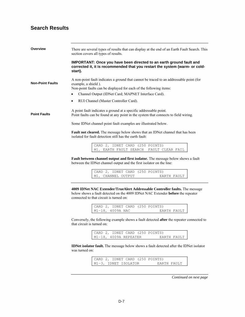
D-7
There are several types of results that can display at the end of an Earth Fault Search. This section covers all types of results. IMPORTANT: Once you have been directed to an earth ground fault and corrected it, it is recommended that you restart the system (warm- or cold-start). A non-point fault indicates a ground that cannot be traced to an addressable point (for example, a shield ). Non-point faults can be displayed for each of the following items:
Channel Output (IDNet Card; MAPNET Interface Card).
RUI Channel (Master Controller Card). A point fault indicates a ground at a specific addressable point. Point faults can be found at any point in the system that connects to field wiring. Some IDNet channel point fault examples are illustrated below. Fault not cleared. The message below shows that an IDNet channel that has been isolated for fault detection still has the earth fault:
CARD 2, IDNET CARD (250 POINTS) M1, EARTH FAULT SEARCH FAULT CLEAR FAIL
Fault between channel output and first isolator. The message below shows a fault between the IDNet channel output and the first isolator on the line:
CARD 2, IDNET CARD (250 POINTS) M1, CHANNEL OUTPUT EARTH FAULT
4009 IDNet NAC Extender/TrueAlert Addressable Controller faults. The message below shows a fault detected on the 4009 IDNet NAC Extender before the repeater connected to that circuit is turned on:
CARD 2, IDNET CARD (250 POINTS) M1-18, 4009A NAC EARTH FAULT
Conversely, the following example shows a fault detected after the repeater connected to that circuit is turned on:
CARD 2, IDNET CARD (250 POINTS) M1-18, 4009A REPEATER EARTH FAULT
IDNet isolator fault. The message below shows a fault detected after the IDNet isolator was turned on:
CARD 2, IDNET CARD (250 POINTS) M1-3, IDNET ISOLATOR EARTH FAULT
Continued on next page
Search Results
Overview
Non-Point Faults
Point Faults
D-8
If the message reads FAULT NOT FOUND (for a Location Earth Fault Search) or FAULT CLEAR FAIL (for an IDNet Channel Earth Fault Search), it means the search could not locate the fault, but it acknowledges that a fault exists. There are several main possibilities behind this message:
There are one or more internal wiring earth(s) in the system.
There are system defects (hardware or software, such as a failed isolation circuit).
An intermittent earth exists in the system (it occurs inconsistently and is therefore difficult to track via diagnostics).
The cable to the service port may be grounded due to the remote PC's 3-prong plug. Use a non-grounded plug adapter to the remote PC to get rid of the earth ground.
The fault is on an auxiliary output that was excluded from the search.
The problem may have to be found manually and then corrected in some of the above scenarios.
If the message reads NO FAULT, it means the IDNet channel search could not locate any earth faults on that channel.
If the message reads RESULT NOT AVAILABLE, it means there is no result to view. This message comes up only when you have selected "Last Search Result" on the menu.
Search Results, Continued
Fault Not Found
No Fault
Result Not Available
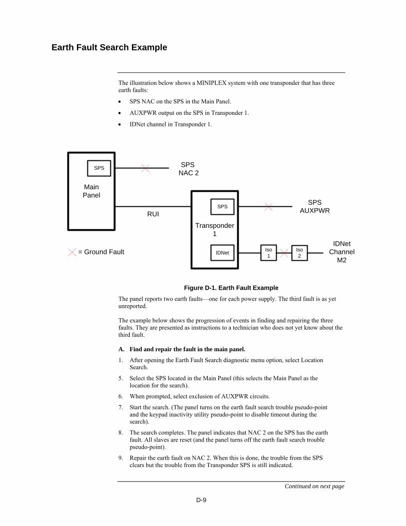
D-9
The illustration below shows a MINIPLEX system with one transponder that has three earth faults:
SPS NAC on the SPS in the Main Panel.
AUXPWR output on the SPS in Transponder 1.
IDNet channel in Transponder 1.
Transponder 1
MainPanel
RUI
SPS NAC 2
SPSAUXPWR
Iso1
Iso2
= Ground Fault
SPS
SPS
IDNet
IDNet Channel
M2
Figure D-1. Earth Fault Example
The panel reports two earth faults—one for each power supply. The third fault is as yet unreported. The example below shows the progression of events in finding and repairing the three faults. They are presented as instructions to a technician who does not yet know about the third fault. A. Find and repair the fault in the main panel.
1. After opening the Earth Fault Search diagnostic menu option, select Location Search.
5. Select the SPS located in the Main Panel (this selects the Main Panel as the location for the search).
6. When prompted, select exclusion of AUXPWR circuits.
7. Start the search. (The panel turns on the earth fault search trouble pseudo-point and the keypad inactivity utility pseudo-point to disable timeout during the search).
8. The search completes. The panel indicates that NAC 2 on the SPS has the earth fault. All slaves are reset (and the panel turns off the earth fault search trouble pseudo-point).
9. Repair the earth fault on NAC 2. When this is done, the trouble from the SPS clears but the trouble from the Transponder SPS is still indicated.
Continued on next page
Earth Fault Search Example

D-10
B. Find and repair the indicated fault on Transponder 1.
1. Select Location Search.
2. Select the SPS located in Transponder 1 (this selects Transponder 1 as the location for the search).
3. When prompted, select exclusion of AUXPWR circuits.
4. Start the search. (The panel turns on the earth fault search trouble pseudo-point and the keypad inactivity utility pseudo-point to disable timeout during the search).
5. The search completes. The panel indicates FAULT NOT FOUND because the fault is on the excluded AUXPWR circuit. All slaves in Transponder 1 are reset (and the panel turns off the earth fault search trouble pseudo-point).
6. Repeat the search but include the AUXPWR circuit this time.
7. The search completes. The panel indicates a fault on the AUXPWR point on the SPS. All slaves in Transponder 1 are reset (and the panel turns off the earth fault search trouble pseudo-point).
8. Repair the earth fault on AUXPWR.
Even though you have fixed the fault, the trouble from the Transponder SPS is still not clearing. Remember that the only two faults you could see at first were from the two SPS. It is time to find and clear the next fault. C. Find and repair the next indicated fault on Transponder 1.
1. Select Location Search.
2. Select the SPS located in Transponder 1.
3. When prompted, select exclusion of AUXPWR circuits.
4. Start the search.
5. The search completes. The panel indicates a fault on IDNet Channel M2.
6. Start another search, this time an IDNet Channel Search on Channel M2.
7. When prompted, select exclusion of AUXPWR circuits.
8. The search completes. The panel indicates a fault on the IDNet channel between isolators 1 and 2.
9. Repair the earth fault. The trouble from the SPS is cleared.
Earth Fault Search Example, Continued
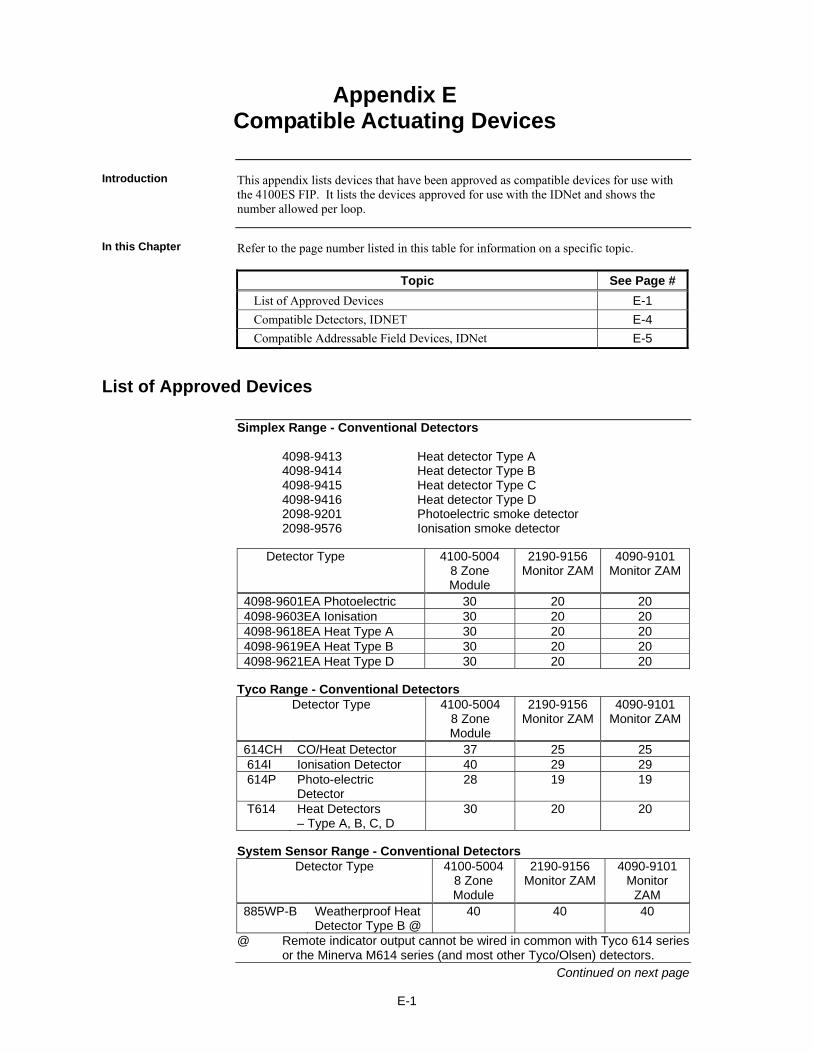
E-1
This appendix lists devices that have been approved as compatible devices for use with the 4100ES FIP. It lists the devices approved for use with the IDNet and shows the number allowed per loop.
Refer to the page number listed in this table for information on a specific topic.
Topic See Page #
List of Approved Devices E-1
Compatible Detectors, IDNET E-4
Compatible Addressable Field Devices, IDNet E-5
Simplex Range - Conventional Detectors 4098-9413 Heat detector Type A 4098-9414 Heat detector Type B 4098-9415 Heat detector Type C 4098-9416 Heat detector Type D 2098-9201 Photoelectric smoke detector 2098-9576 Ionisation smoke detector Detector Type 4100-5004
8 Zone Module
2190-9156 Monitor ZAM
4090-9101 Monitor ZAM
4098-9601EA Photoelectric 30 20 20 4098-9603EA Ionisation 30 20 20 4098-9618EA Heat Type A 30 20 20 4098-9619EA Heat Type B 30 20 20 4098-9621EA Heat Type D 30 20 20
Tyco Range - Conventional Detectors
Detector Type 4100-5004 8 Zone Module
2190-9156 Monitor ZAM
4090-9101 Monitor ZAM
614CH CO/Heat Detector 37 25 25 614I Ionisation Detector 40 29 29 614P Photo-electric
Detector 28 19 19
T614 Heat Detectors – Type A, B, C, D
30 20 20
System Sensor Range - Conventional Detectors
Detector Type 4100-5004 8 Zone Module
2190-9156 Monitor ZAM
4090-9101 Monitor
ZAM 885WP-B Weatherproof Heat
Detector Type B @ 40 40 40
@ Remote indicator output cannot be wired in common with Tyco 614 series or the Minerva M614 series (and most other Tyco/Olsen) detectors.
Continued on next page
Appendix E Compatible Actuating Devices
Introduction
In this Chapter
List of Approved Devices
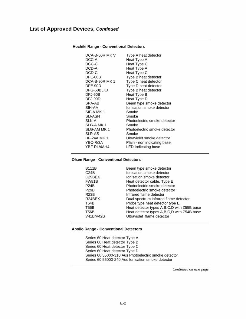
E-2
Hochiki Range - Conventional Detectors DCA-B-60R MK V Type A heat detector DCC-A Heat Type A DCC-C Heat Type C DCD-A Heat Type A DCD-C Heat Type C DFE-60B Type B heat detector DCA-B-90R MK 1 Type C heat detector DFE-90D Type D heat detector DFG-60BLKJ Type B heat detector DFJ-60B Heat Type B DFJ-90D Heat Type D SPA-AB Beam type smoke detector SIH-AM Ionisation smoke detector SIF-A MK 1 Smoke SIJ-ASN Smoke SLK-A Photoelectric smoke detector SLG-A MK 1 Smoke SLG-AM MK 1 Photoelectric smoke detector SLR-AS Smoke HF-24A MK 1 Ultraviolet smoke detector YBC-R/3A Plain - non indicating base YBF-RL/4AH4 LED Indicating base
Olsen Range - Conventional Detectors B111B Beam type smoke detector C24B Ionisation smoke detector C29BEX Ionisation smoke detector FW81B Heat detector cable, Type E P24B Photoelectric smoke detector P29B Photoelectric smoke detector R23B Infrared flame detector R24BEX Dual spectrum infrared flame detector T54B Probe type heat detector type E T56B Heat detector types A,B,C,D with Z55B base T56B Heat detector types A,B,C,D with Z54B base V41B/V42B Ultraviolet flame detector
Apollo Range - Conventional Detectors Series 60 Heat detector Type A Series 60 Heat detector Type B Series 60 Heat detector Type C Series 60 Heat detector Type D Series 60 55000-310 Aus Photoelectric smoke detector Series 60 55000-240 Aus Ionisation smoke detector
Continued on next page
List of Approved Devices, Continued
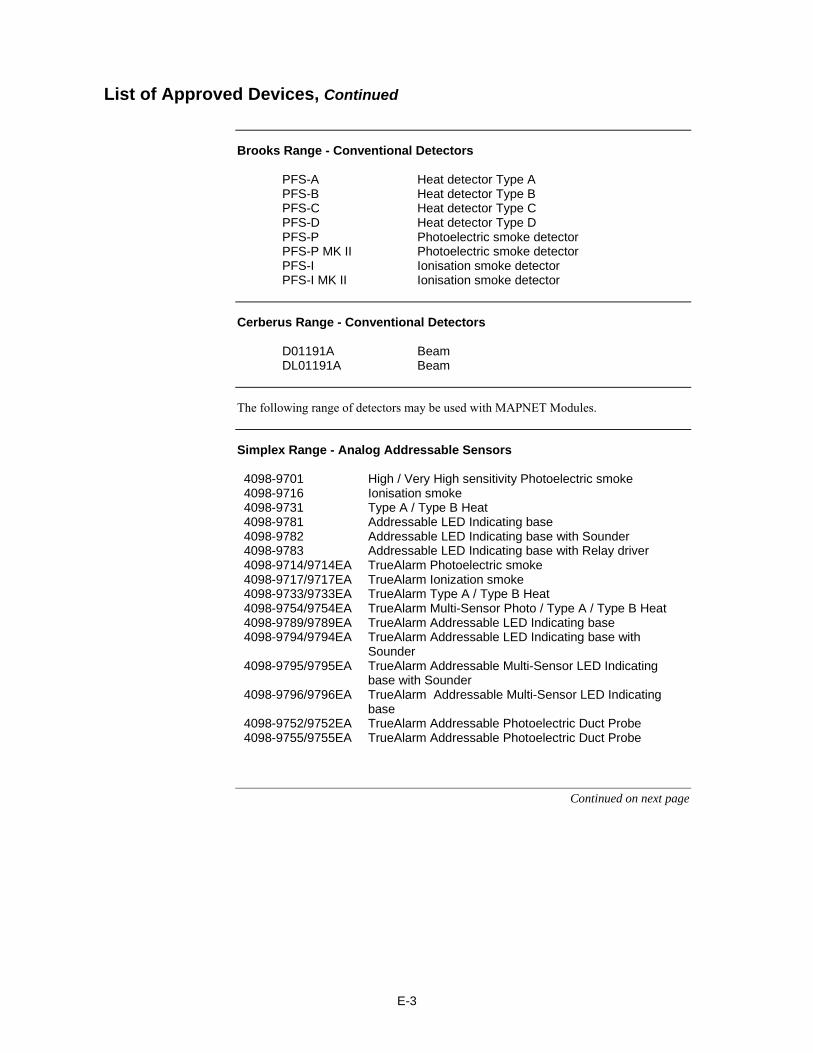
E-3
Brooks Range - Conventional Detectors PFS-A Heat detector Type A PFS-B Heat detector Type B PFS-C Heat detector Type C PFS-D Heat detector Type D PFS-P Photoelectric smoke detector PFS-P MK II Photoelectric smoke detector PFS-I Ionisation smoke detector PFS-I MK II Ionisation smoke detector
Cerberus Range - Conventional Detectors D01191A Beam DL01191A Beam
The following range of detectors may be used with MAPNET Modules.
Simplex Range - Analog Addressable Sensors 4098-9701 High / Very High sensitivity Photoelectric smoke 4098-9716 Ionisation smoke 4098-9731 Type A / Type B Heat 4098-9781 Addressable LED Indicating base 4098-9782 Addressable LED Indicating base with Sounder 4098-9783 Addressable LED Indicating base with Relay driver 4098-9714/9714EA TrueAlarm Photoelectric smoke 4098-9717/9717EA TrueAlarm Ionization smoke 4098-9733/9733EA TrueAlarm Type A / Type B Heat 4098-9754/9754EA TrueAlarm Multi-Sensor Photo / Type A / Type B Heat 4098-9789/9789EA TrueAlarm Addressable LED Indicating base 4098-9794/9794EA TrueAlarm Addressable LED Indicating base with
Sounder 4098-9795/9795EA TrueAlarm Addressable Multi-Sensor LED Indicating
base with Sounder 4098-9796/9796EA TrueAlarm Addressable Multi-Sensor LED Indicating
base 4098-9752/9752EA TrueAlarm Addressable Photoelectric Duct Probe 4098-9755/9755EA TrueAlarm Addressable Photoelectric Duct Probe
Continued on next page
List of Approved Devices, Continued
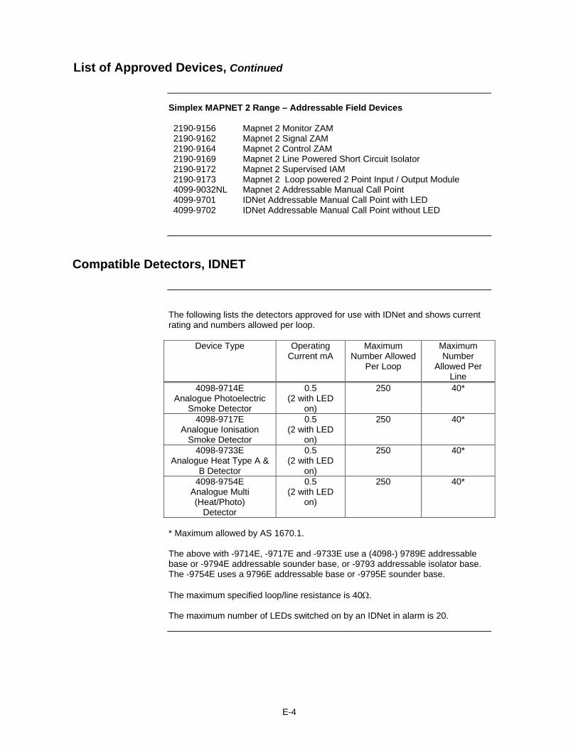
E-4
Simplex MAPNET 2 Range – Addressable Field Devices 2190-9156 Mapnet 2 Monitor ZAM 2190-9162 Mapnet 2 Signal ZAM 2190-9164 Mapnet 2 Control ZAM 2190-9169 Mapnet 2 Line Powered Short Circuit Isolator 2190-9172 Mapnet 2 Supervised IAM 2190-9173 Mapnet 2 Loop powered 2 Point Input / Output Module 4099-9032NL Mapnet 2 Addressable Manual Call Point 4099-9701 IDNet Addressable Manual Call Point with LED 4099-9702 IDNet Addressable Manual Call Point without LED
The following lists the detectors approved for use with IDNet and shows current rating and numbers allowed per loop.
Device Type Operating Current mA
Maximum Number Allowed
Per Loop
Maximum Number
Allowed Per Line
4098-9714E Analogue Photoelectric
Smoke Detector
0.5 (2 with LED
on)
250 40*
4098-9717E Analogue Ionisation
Smoke Detector
0.5 (2 with LED
on)
250 40*
4098-9733E Analogue Heat Type A &
B Detector
0.5 (2 with LED
on)
250 40*
4098-9754E Analogue Multi (Heat/Photo)
Detector
0.5 (2 with LED
on)
250 40*
* Maximum allowed by AS 1670.1. The above with -9714E, -9717E and -9733E use a (4098-) 9789E addressable base or -9794E addressable sounder base, or -9793 addressable isolator base. The -9754E uses a 9796E addressable base or -9795E sounder base. The maximum specified loop/line resistance is 40. The maximum number of LEDs switched on by an IDNet in alarm is 20.
List of Approved Devices, Continued
Compatible Detectors, IDNET
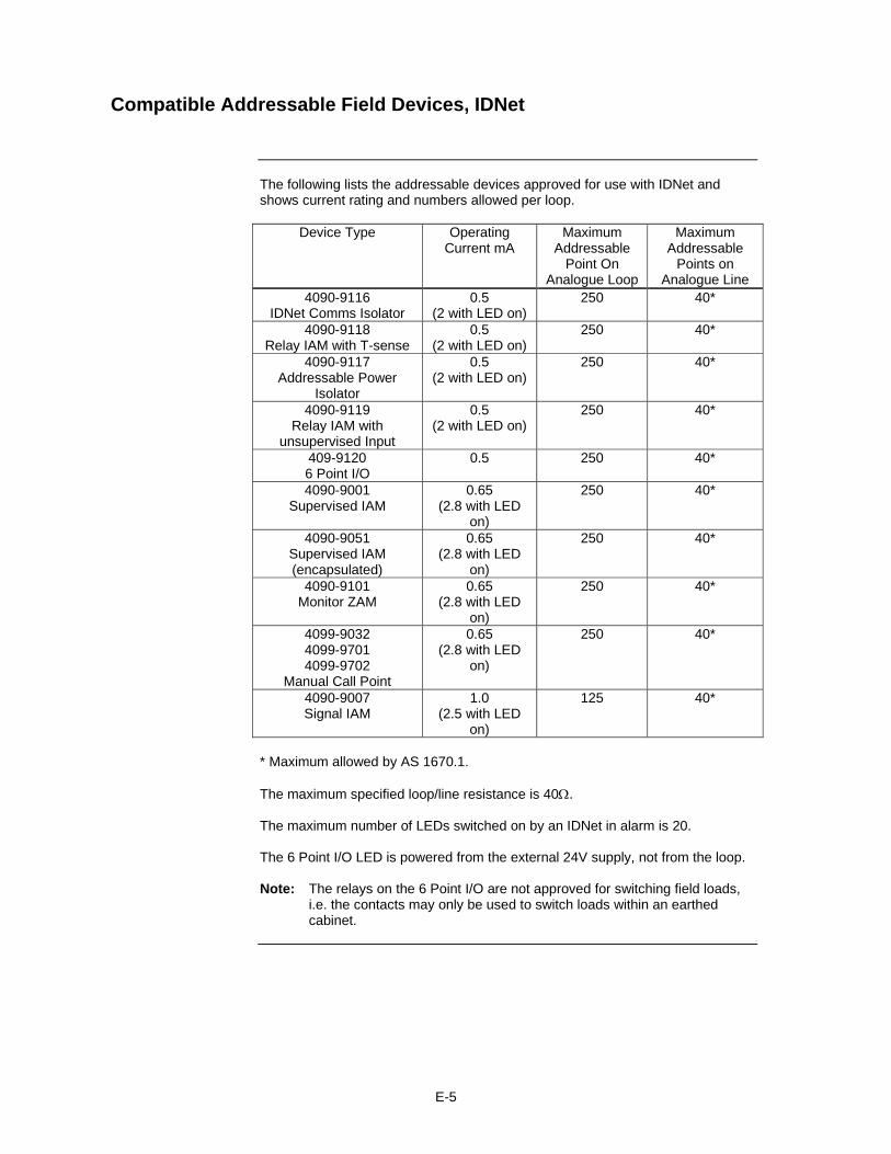
E-5
The following lists the addressable devices approved for use with IDNet and shows current rating and numbers allowed per loop.
Device Type Operating Current mA
Maximum Addressable
Point On Analogue Loop
Maximum Addressable
Points on Analogue Line
4090-9116 IDNet Comms Isolator
0.5 (2 with LED on)
250 40*
4090-9118 Relay IAM with T-sense
0.5 (2 with LED on)
250 40*
4090-9117 Addressable Power
Isolator
0.5 (2 with LED on)
250 40*
4090-9119 Relay IAM with
unsupervised Input
0.5 (2 with LED on)
250 40*
409-9120 6 Point I/O
0.5 250 40*
4090-9001 Supervised IAM
0.65 (2.8 with LED
on)
250 40*
4090-9051 Supervised IAM (encapsulated)
0.65 (2.8 with LED
on)
250 40*
4090-9101 Monitor ZAM
0.65 (2.8 with LED
on)
250 40*
4099-9032 4099-9701 4099-9702
Manual Call Point
0.65 (2.8 with LED
on)
250 40*
4090-9007 Signal IAM
1.0 (2.5 with LED
on)
125 40*
* Maximum allowed by AS 1670.1. The maximum specified loop/line resistance is 40. The maximum number of LEDs switched on by an IDNet in alarm is 20. The 6 Point I/O LED is powered from the external 24V supply, not from the loop. Note: The relays on the 6 Point I/O are not approved for switching field loads, i.e. the contacts may only be used to switch loads within an earthed cabinet.
Compatible Addressable Field Devices, IDNet

E-6
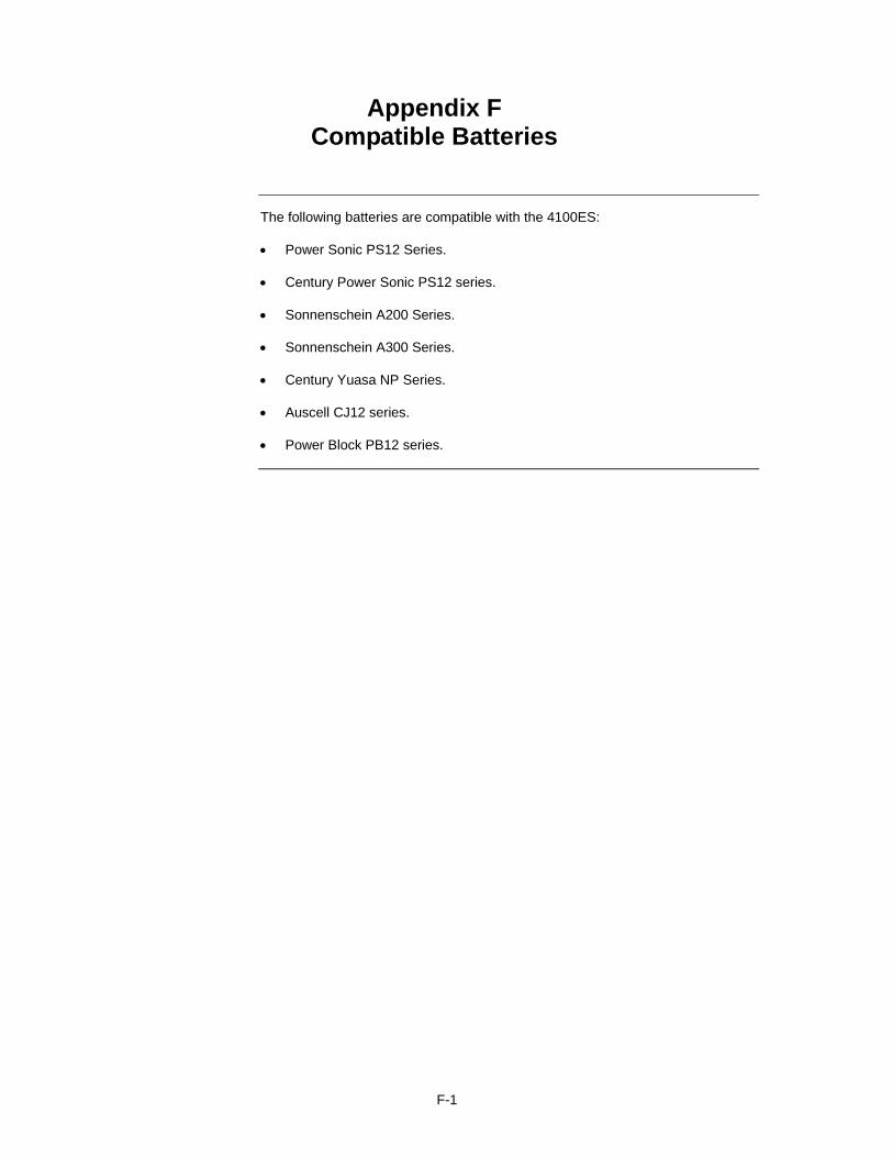
F-1
The following batteries are compatible with the 4100ES: Power Sonic PS12 Series.
Century Power Sonic PS12 series.
Sonnenschein A200 Series.
Sonnenschein A300 Series.
Century Yuasa NP Series.
Auscell CJ12 series.
Power Block PB12 series.
Appendix F Compatible Batteries

F-2
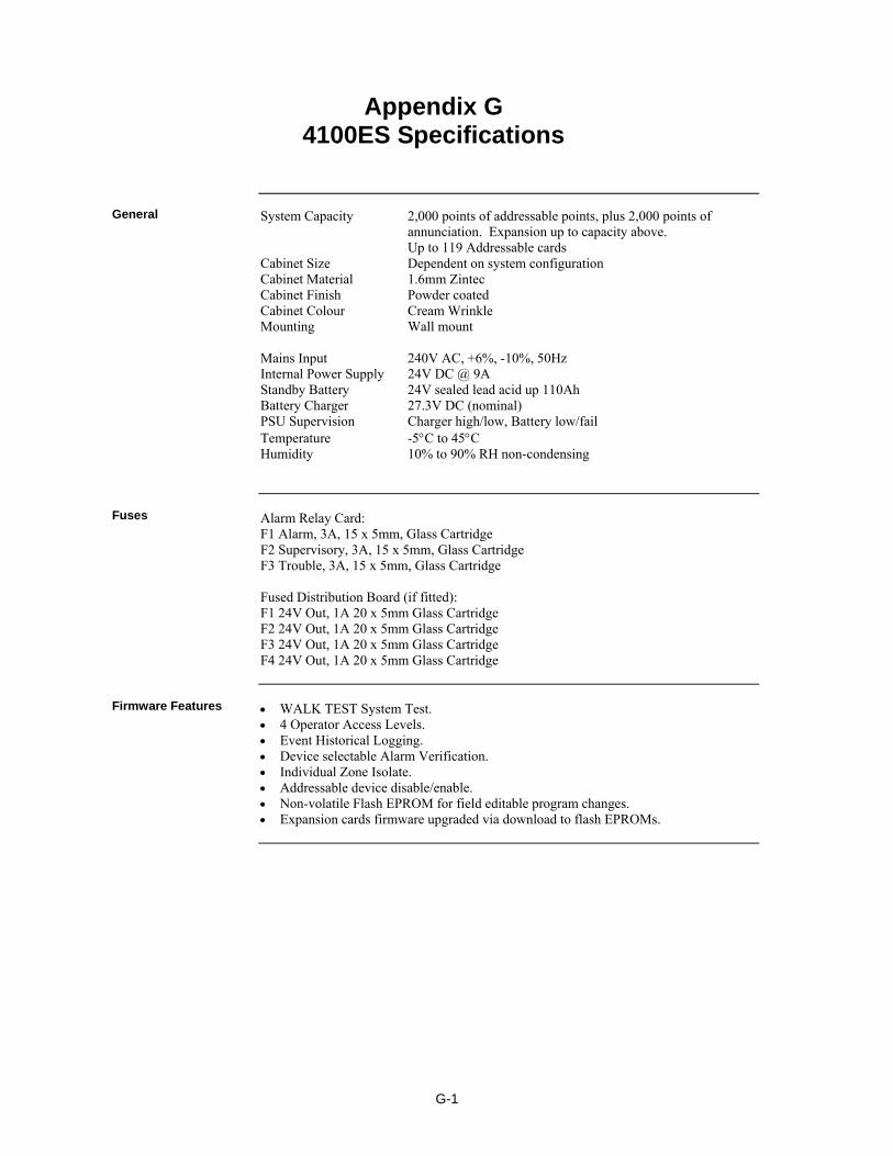
G-1
System Capacity 2,000 points of addressable points, plus 2,000 points of annunciation. Expansion up to capacity above. Up to 119 Addressable cards Cabinet Size Dependent on system configuration Cabinet Material 1.6mm Zintec Cabinet Finish Powder coated Cabinet Colour Cream Wrinkle Mounting Wall mount Mains Input 240V AC, +6%, -10%, 50Hz Internal Power Supply 24V DC @ 9A Standby Battery 24V sealed lead acid up 110Ah Battery Charger 27.3V DC (nominal) PSU Supervision Charger high/low, Battery low/fail Temperature -5C to 45C Humidity 10% to 90% RH non-condensing Alarm Relay Card: F1 Alarm, 3A, 15 x 5mm, Glass Cartridge F2 Supervisory, 3A, 15 x 5mm, Glass Cartridge F3 Trouble, 3A, 15 x 5mm, Glass Cartridge Fused Distribution Board (if fitted): F1 24V Out, 1A 20 x 5mm Glass Cartridge F2 24V Out, 1A 20 x 5mm Glass Cartridge F3 24V Out, 1A 20 x 5mm Glass Cartridge F4 24V Out, 1A 20 x 5mm Glass Cartridge WALK TEST System Test. 4 Operator Access Levels. Event Historical Logging. Device selectable Alarm Verification. Individual Zone Isolate. Addressable device disable/enable. Non-volatile Flash EPROM for field editable program changes. Expansion cards firmware upgraded via download to flash EPROMs.
Appendix G 4100ES Specifications
General
Fuses
Firmware Features

G-2
The DC input voltage range of the following modules is 18-33VDC. The current listed is nominal for 24VDC, and may be used for battery capacity calculations. Module Name Quiescent Alarm N/A Master Controller Assembly
(includes SPS, CPU, CPU Motherboard with RUI I/F, Operator Interface with LCD)
373mA 470mA
4100-6035 Alarm Relay Card 15mA 37mA 4100-3101 IDNet Module without Devices
- per device add - with 250 devices add
75mA 0.8mA 200mA
115mA 1mA 250mA
4100-1289 64/64 Controller plus Switch LED Modules - no LED on - per LED on add - with 64 LEDs on add
20mA 3mA 210mA
3mA 210mA
4100-0620 Transponder Interface, Basic Unit 87mA 87mA 4100-0625 Transponder Interface, Local Mode 112mA 112mA 4100-6014 Network Interface Card 28mA 28mA 4100-6056 Wired Media Module 55mA 55mA 4100-6057 Fibre Optic Media Module 25mA 25mA 4100-6038 Dual RS232 Interface 132mA 132mA
Voltage & Current Ratings of Modules & Assemblies

H-1
Part of the system design includes calculating that the quiescent load and the alarm load are each less than the rating of the power supply. Note that the quiescent load includes devices such as door holders that are normally energized, but get switched off during alarm. The SPS rating is included in the specifications in Chapter 5. Refer to AS 1670.1 Section 8.2.3 for a definition of the loads to be calculated. Battery capacity requirements are specified in AS 1670.1, 2004, Section 3.16.4 with an example shown in Appendix C1. Calculate the quiescent load (Iq) and alarm load (Ia) from the currents listed in the specifications (Appendix G of this manual). Follow the example in AS 1670.1. Note that the system current for both the quiescent and the alarm state can be checked on the panel by use of the System Current status point under Card Status for the SPS.
Appendix H Power Supply & Battery Capacity Calculations
Power Supply
Battery Capacity

H-2

J-1
The IDNet cabling requirements are detailed in Chapter 7 of this manual. Line Characteristics Note: In the following paragraphs the term "MAPNET channel" is used to mean those lines connected to any one Mapnet Transceiver board. Parallel runs from the same board do not constitute separate channels. The term "continuous run" refers to the loop distance from the primary output, through all devices and back to the secondary output. Line characteristics are based on 0.58uF and/or 35 Ohms total line resistance. Total length of line on one MAPNET channel shall not exceed 3,000 m including all T-taps and parallel runs. Maximum length for ONE continuous MAPNET run is 1200 m for up to 128 MAPNET devices using 1.5 mm sq cable. When the run exceeds 850 m it is necessary to use twisted, shielded pair. Copper Line Characteristics Network "Wired" (formerly called RS-485) Communication wiring must be 0.75 mm sq twisted, shielded pair (TSP), or 0.22 mm sq twisted pair (TP). Shielded Cable is recommended for new installations. When shielding is used, the shield shall be connected to Earth Ground, at the Left Port end of span only. No T-tapping of the Network conductors is allowed. Network wiring is point-to-point, only. Maximum line length between ports at 57,600 and 9600 bits per second is shown in the table below.
Table J- 1 Network: Maximum Transmission Distances, "Wired" Network Maximum Wiring Distance
Communication Speed 0.75mm sq TSP Wire. (Maximum capacitance between conductors is 174 pf. per meter)
0.22mm sq TP Wire. (Maximum capacitance between conductors is 66 pf. per meter)
57,600 bps 3,000 m 2,300 m
9600 bps 5,600 m 4,000 m
Continued on next page
Appendix J Cable Characteristics
IDNet
4100 MAPNET II
NETWORK
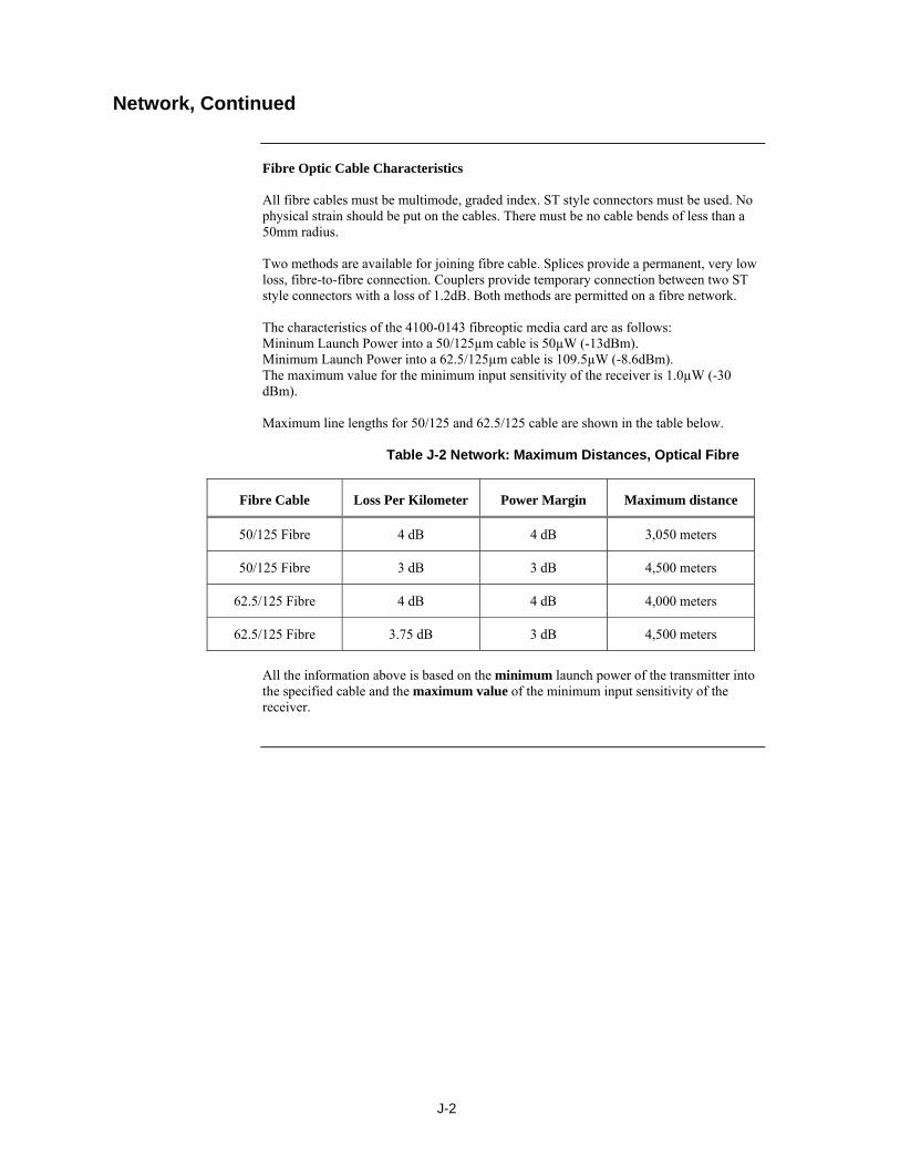
J-2
Fibre Optic Cable Characteristics All fibre cables must be multimode, graded index. ST style connectors must be used. No physical strain should be put on the cables. There must be no cable bends of less than a 50mm radius. Two methods are available for joining fibre cable. Splices provide a permanent, very low loss, fibre-to-fibre connection. Couplers provide temporary connection between two ST style connectors with a loss of 1.2dB. Both methods are permitted on a fibre network. The characteristics of the 4100-0143 fibreoptic media card are as follows: Mininum Launch Power into a 50/125µm cable is 50µW (-13dBm). Minimum Launch Power into a 62.5/125µm cable is 109.5µW (-8.6dBm). The maximum value for the minimum input sensitivity of the receiver is 1.0µW (-30 dBm). Maximum line lengths for 50/125 and 62.5/125 cable are shown in the table below.
Table J-2 Network: Maximum Distances, Optical Fibre
Fibre Cable Loss Per Kilometer Power Margin Maximum distance
50/125 Fibre 4 dB 4 dB 3,050 meters
50/125 Fibre 3 dB 3 dB 4,500 meters
62.5/125 Fibre 4 dB 4 dB 4,000 meters
62.5/125 Fibre 3.75 dB 3 dB 4,500 meters
All the information above is based on the minimum launch power of the transmitter into the specified cable and the maximum value of the minimum input sensitivity of the receiver.
Network, Continued

K-1
This table lists the ordering codes for the spare parts that may be needed to maintain this 4100ES panel. The first column lists the expected numbers that may be readily visible on the part being replaced as an aid to identifying what it is, if this is not obvious from other information. Possible markings on the part
Description Order code for replacement spare part
CPU Card and Motherboard 0566719 578‐643
4100ES NXP CPU Upgrade Kit 4100‐7158K
566‐227 4100ES/4100U CPU Motherboard only 742‐516
Front display doors and display modules 743‐327 INFOALARM ON 8U DOOR, AU SPARE 4100‐ME0498 743‐327 INFOALARM,AU SPARE/UPGRADE KIT, BAY
MOUNTED 4100‐7155K
none 7U ZONE LED DOOR EMPTY SPARE 4100‐KT0549K 4100‐1288 566‐060 741‐206
64/64 LED/Switch Controller and mounting frame (1st controller in a bay)
4100‐1288
566‐060 741‐206
64/64 LED/Switch Controller (2nd controller in a bay)
4100‐1289
4100‐1277 742‐983
8 Red and 8 Yellow LED Module 4100‐1277
4100‐1280 742‐509
8 Pushbutton 8 Red LED Module 4100‐1280
4100‐1284 742‐407
8/16 Push Button/Red‐Green LED Module 4100‐1284
4100‐1282 742‐408
8/16 Push Button/Red‐Yellow LED Module 4100‐1282
4100‐1281 742‐508
8 Pushbutton 8 Yellow LED Module 4100‐1281
4100‐1287 742‐506
24 Push Button 24 LED Module 4100‐1287
1976‐149 PA1029
4 x AS1668 Control Module 4100‐ME0456
4100‐1279 742‐519
Single Blank Display Cover (4100ES or 4100U)
4100‐1279
4100‐9443AU INFOALARM REMOTE DISPLAY PLATINUM 4100‐9443AU
Continued on next page
Appendix K List of Spare Parts
Spare Part Order Codes
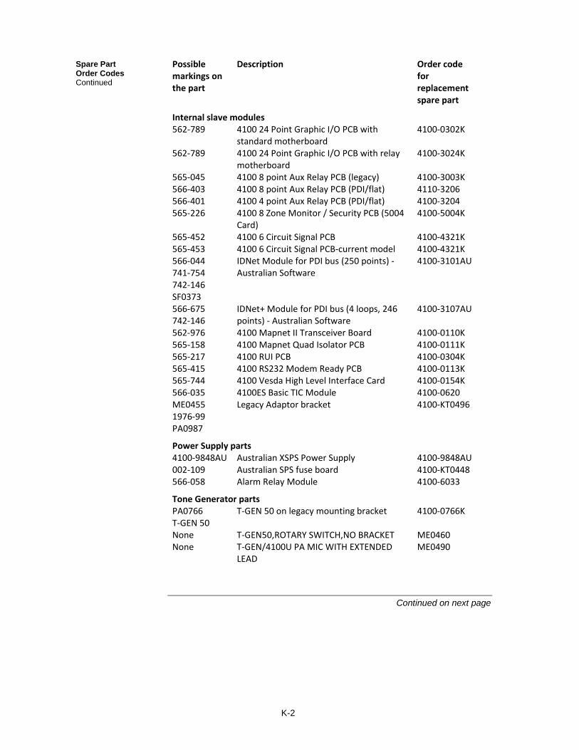
K-2
Possible markings on the part
Description Order code for replacement spare part
Internal slave modules 562‐789 4100 24 Point Graphic I/O PCB with
standard motherboard 4100‐0302K
562‐789 4100 24 Point Graphic I/O PCB with relay motherboard
4100‐3024K
565‐045 4100 8 point Aux Relay PCB (legacy) 4100‐3003K 566‐403 4100 8 point Aux Relay PCB (PDI/flat) 4110‐3206 566‐401 4100 4 point Aux Relay PCB (PDI/flat) 4100‐3204 565‐226 4100 8 Zone Monitor / Security PCB (5004
Card) 4100‐5004K
565‐452 4100 6 Circuit Signal PCB 4100‐4321K 565‐453 4100 6 Circuit Signal PCB‐current model 4100‐4321K 566‐044 741‐754 742‐146 SF0373
IDNet Module for PDI bus (250 points) ‐ Australian Software
4100‐3101AU
566‐675 742‐146
IDNet+ Module for PDI bus (4 loops, 246 points) ‐ Australian Software
4100‐3107AU
562‐976 4100 Mapnet II Transceiver Board 4100‐0110K 565‐158 4100 Mapnet Quad Isolator PCB 4100‐0111K 565‐217 4100 RUI PCB 4100‐0304K 565‐415 4100 RS232 Modem Ready PCB 4100‐0113K 565‐744 4100 Vesda High Level Interface Card 4100‐0154K 566‐035 4100ES Basic TIC Module 4100‐0620 ME0455 1976‐99 PA0987
Legacy Adaptor bracket 4100‐KT0496
Power Supply parts 4100‐9848AU Australian XSPS Power Supply 4100‐9848AU 002‐109 Australian SPS fuse board 4100‐KT0448 566‐058 Alarm Relay Module 4100‐6033
Tone Generator parts PA0766 T‐GEN 50
T‐GEN 50 on legacy mounting bracket 4100‐0766K
None T‐GEN50,ROTARY SWITCH,NO BRACKET ME0460 None T‐GEN/4100U PA MIC WITH EXTENDED
LEAD ME0490
Continued on next page
Spare Part Order Codes Continued
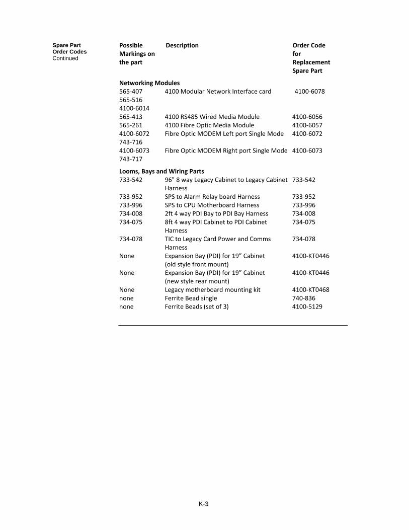
K-3
Possible Description Order Code Markings on for the part Replacement Spare Part
Networking Modules 565‐407 565‐516 4100‐6014
4100 Modular Network Interface card 4100‐6078
565‐413 4100 RS485 Wired Media Module 4100‐6056 565‐261 4100 Fibre Optic Media Module 4100‐6057 4100‐6072 743‐716
Fibre Optic MODEM Left port Single Mode 4100‐6072
4100‐6073 743‐717
Fibre Optic MODEM Right port Single Mode 4100‐6073
Looms, Bays and Wiring Parts 733‐542 96" 8 way Legacy Cabinet to Legacy Cabinet
Harness 733‐542
733‐952 SPS to Alarm Relay board Harness 733‐952 733‐996 SPS to CPU Motherboard Harness 733‐996 734‐008 2ft 4 way PDI Bay to PDI Bay Harness 734‐008 734‐075 8ft 4 way PDI Cabinet to PDI Cabinet
Harness 734‐075
734‐078 TIC to Legacy Card Power and Comms Harness
734‐078
None Expansion Bay (PDI) for 19” Cabinet (old style front mount)
4100‐KT0446
None Expansion Bay (PDI) for 19” Cabinet (new style rear mount)
4100‐KT0446
None Legacy motherboard mounting kit 4100‐KT0468 none Ferrite Bead single 740‐836 none Ferrite Beads (set of 3) 4100‐5129
Spare Part Order Codes Continued

K-4

L-1
The following drawings are included as they are referred to in this manual. 1922-96 Sheet 1 WA ASE Wiring & Mounting Details 1922-96 Sheet 2 Cube ASE Wiring & Mounting Details 1976-174 Sheet 1 Centaur ASE Wiring & Mounting Details Additional wiring instructions for 4100 modules and addressable devices can be found in the 1976-181 drawings, which are collected in LT0432 4100ES Australian Wiring Diagrams.
Appendix L List of Drawings
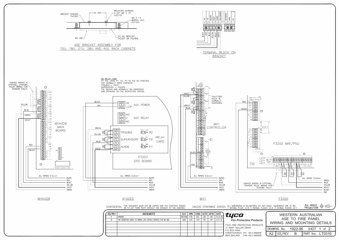
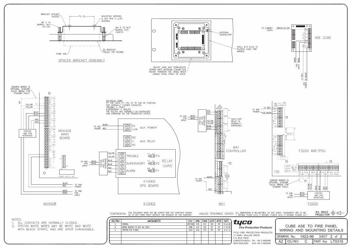
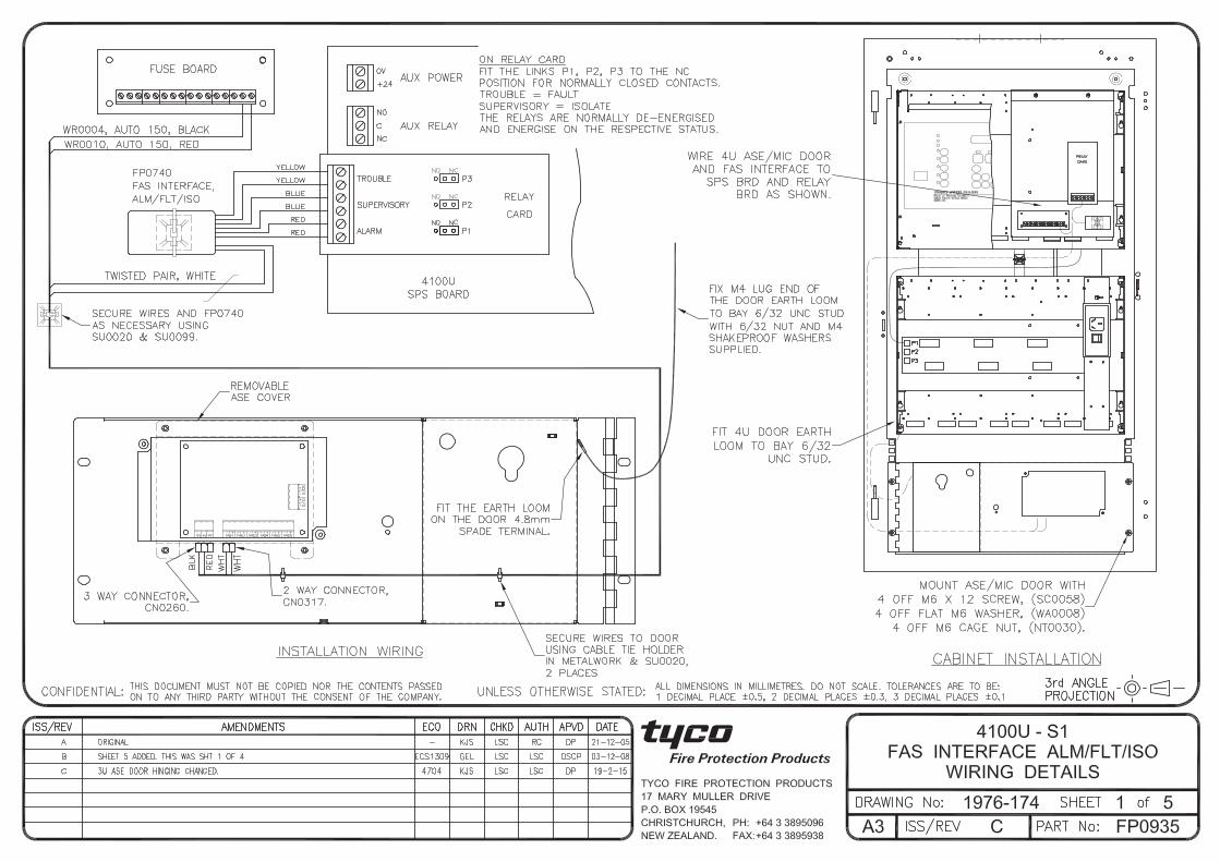

©2004 Tyco Safety Products Westminster, Westminster, MA 01441-001 USA. Specifications and other information shown were current as of publication, and are subject to change without notice.


