Approved for Public Release 1 Approved for Public Release 1 45 th AIAA/ASME/SAE/ASEE Joint Propulsion Conference & Exhibit 4 August 2009 Colorado Convention Center Denver, Colorado Panel Session on
Transcript
Approved for Public Release 1Approved for Public Release 1
Approved for Public Release 2Approved for Public Release 2
Panel Members
Bruce Wood, Pratt & WhitneyDerek Weber, Inprox TechnologyBill Rhoden, Hamilton-SundstrandBill Mailander, GE AviationGary Hunter, NASA Glenn Research CenterDennis Culley, NASA Glenn Research CenterCasey Carter, BAE SystemsDewey Benson, HoneywellAl Behbahani, Air Force Research Laboratory
Approved for Public Release 3Approved for Public Release 3
Outline
• Motivation / Objective• Collaborative Hardware Demonstration• Vision & Need for Future Turbine Engine Control• Implementation & Technical Challenges• High Temperature Electronics• Innovation• Summary & Future Plans
Approved for Public Release 4Approved for Public Release 4
Motivation / Objective
• Are engine control systems keeping pace with turbine engine system needs?
• What technologies are required for existing and future engine control systems?
• How Do & Why Should engine control systems take advantage of emerging electronics and control technologies?
• What is the go-forward plan for the turbine engine controls community?
Approved for Public Release 5Approved for Public Release 5
Traditional Centralized Architecture
Approved for Public Release 6Approved for Public Release 6
Example of Distributed Architecture TIM___________________________
TIM___________________________
TIM___________________________
TIM___________________________
TIM___________________________
TIM___________________________
TIM___________________________
TIM___________________________
SmartNode
Approved for Public Release 7Approved for Public Release 7
Thoughts to Keep in Mind
• Turbine engine controls have made transitions to new technologies in the past – what were the driving factors behind these changes?
• What is the relationship between the electronics industry and mission critical electronics applications like turbine engine control systems?
Approved for Public Release 8Approved for Public Release 8
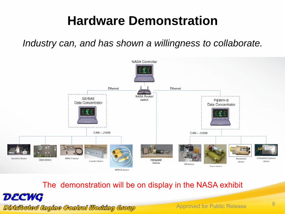
Hardware DemonstrationIndustry can, and has shown a willingness to collaborate.
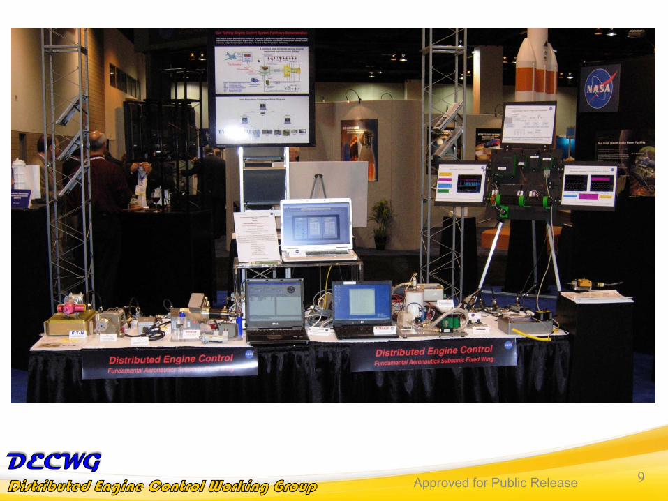
The demonstration will be on display in the NASA exhibit
Approved for Public Release 9Approved for Public Release 9
Approved for Public Release 10Approved for Public Release 10
Contributors to the DemonstrationBAE SystemsEaton Corp.Embedded Systems, LLCGeneral ElectricGoodrich Corp.Hamilton SundstrandHoneywellImpact Technologies, LLCInprox TechnologyLuraco TechnologiesNASAPratt & WhitneyScientific Monitoring Inc / Haric, LLCWoodward Governor Company
Approved for Public Release 1111
Bruce WoodBrian Easton
Pratt & Whitney
Bill MailanderGE Aviation
Alireza BehbahaniAir Force Research Laboratory
Approved for Public Release 12Approved for Public Release 12
Technical Requirements for Distributed Controls
Physical Drivers for New Control System Designs• Thermal Environment• Externals Packaging• Rapid Reconfiguration / Upgradability• Generic Physical/Functional Interface• Environmental Requirements• Certification Impact• Integration Testing• Financial Responsibility
Focus on Near-Term Applications • Concentrate on commercial applications with production volumes • Design for maximum leveraging though multiple applications
Approved for Public Release 13Approved for Public Release 13
Technical Requirements for Distributed Controls
Thermal Environment• Design electronics to withstand existing hardware thermal conditions• Recognize limitations of typical industry materials• Aluminums (300F/149C), Elastomers (350F/177F)
Externals Packaging • Need to integrate electronics onto or within existing hardware • Minimize unique hardware• Adding new/extra mounting hardware drives cost, weight in the
wrong direction
Approved for Public Release 14Approved for Public Release 14
Technical Requirements for Distributed Controls
Rapid Reconfiguration / Upgradability• Should be able to specify same part number DCM for multiple
applications• Design DCM internal gains such that they can be varied without
hardware changes
Generic Physical/Functional Interface• Similar to the way EHSV interfaces are controlled today (ARP490)• Bolt/connector interfaces should be standardized• Standard functionality, memory, loop closure, communication bit
structure, etc.
Approved for Public Release 15Approved for Public Release 15
Technical Requirements for Distributed Controls
Environmental Requirements• Design for existing ambient temperatures and vibration
environments• Don’t drive cost/complexity into the DCM to withstand unrealistic
margins• Focus on actual engine environments, not D0160/810 generic
requirements
Certification Impact, Changes to Testing• Allow certification at modular level• Require system level certification using black box approach to
testing• Allow flexible system expansion/contraction without recert. required
Approved for Public Release 16Approved for Public Release 16
Technical Requirements for Distributed Controls
Integration testing• System integration testing paradigms will shift• System integration tasks will shift one layer down the food chain
• AS/OS boundaries may drive testing location, integration responsibilities
Financial responsibility• Need to keep focused on cost of products, don’t design and build
beyond our minimum needs (with reasonable margins)• System costs need to make the case for this new technology
• Individual component costs are flexible • Design + Development + Certification + Procurement + Life Cycle
Cost = Net Savings for our Customers
Approved for Public Release 17Approved for Public Release 17
Economic Drivers for New FADEC Designs
FADECs Have Unique Electronics Hardware RequirementsIssues• High Temperature Capable Electronics for FADECs Are Specialty Items• ~20 Years FADEC Production Runs vs. Rapid Consumer Electronics
Turnover• FADEC Electronics Often Nearing Obsolescence At Entry Into Service• “Out-of-Plan” FADEC Obsolescence Turns Are Major Budget ChallengeImplications for Future FADECs• Improved Methods for Enabling Electronics to Tolerate Engine Environment• Use of Common FADEC Electronics Components Supply Base• Exploration of Boutique Manufacturing Supporting Small Quantity
Electronics
Need Broadly Applicable High Temperature Electronics Supply Base
Approved for Public Release 18Approved for Public Release 18
Point-Design FADECs Don’t Support Reuse / Upgradability
Economic Drivers for New FADEC Designs
Not Realizing Cost Benefits from Reuse / UpgradabilityIssues• Point-Designs Typically Increase Initial Cost and Reduce Production
Costs• Upgrades Can Cost As Much As Original FADEC Implementation• FADECs Are Not Designed with Reuse in Mind – No “Pay-It-
Forward”
Implications for Future FADECs• Need to Consider Life Cycle Business Case in Design• Partitioned Architectures Limiting Necessary Re-Validation• Modular and Reconfigurable FADEC Components / Architectures
Approved for Public Release 19Approved for Public Release 19
Economic Drivers for New FADEC Designs
FADEC Implementation Time Pacing Engine Development
Issues• FADEC Definition Usually Lags Engine Definition in Preliminary
Design• Long Development and Validation Times Consumed by for FADECs• Weight / Cost Reduction Campaigns Drive FADEC Iterations
Implications for Future FADECs• Move Away From Point-Design FADECs• Leverage Common FADEC Components / Modules • Safety First / Understand Trades Cost and Weight Trades
Modular FADEC Designs Favor Rapid Implementation
Approved for Public Release 20Approved for Public Release 20
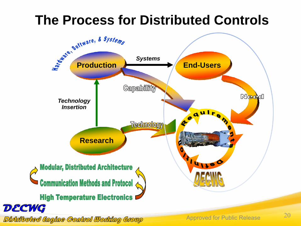
The Process for Distributed Controls
TechnologyInsertion
SystemsEnd-UsersProduction
Research
Approved for Public Release 21Approved for Public Release 21
Objective: Modular, Open, Distributed Engine Control
Increased Performance• Reduction in engine weight due to digital signaling, lower wire/connector count, reduced cooling need
• 5% increase in thrust-to-weight ratioImproved Mission Success• System availability improvement due to automated fault isolation, reduced maintenance time, modular LRU
• 10% increase in system availabilityLower Life Cycle Cost• Reduced cycle time for design, manufacture, V&V
• Reduced component and maintenance costs via cross-platform commonality, obsolescence mitigation
• Flexible upgrade path through open interface standards
Open Systems Development, Modeling & Design• Future systems requirements definition• Open industry interface standards definition
• System modeling tools development• Modular system integration and test techniques
Hardware Systems Development• High temperature integrated circuits and systems development
• Improved electronic component availability
Software Systems Development• Software system partitioning• Software design and modular test capability
• Software distributed system V&V
Approved for Public Release 22Approved for Public Release 22
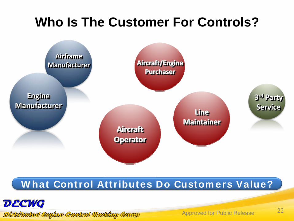
AirframeManufacturer
Who Is The Customer For Controls?
EngineManufacturer
3rd PartyService
Aircraft/EnginePurchaser
AircraftOperator
LineMaintainer
What Control Attributes Do Customers Value?
Approved for Public Release 23Approved for Public Release 23
adapt the system to your needs(Customer Requirements)
Cost
Design
IntegrationCommuni‐cation
There is a need for improved control devices that are compatible with the control electronics made by different manufactures. In
addition there is a need for specific purpose control devices of one manufacturer to be compatible with more general-purpose control
electronics from a different manufacturer.
ReliabilityDependability
Capability
Weight
Engine Manufacturer
Approved for Public Release 24Approved for Public Release 24
Adapt the system to your customer’s and OEM’s needs
Design(Robust tools &
Methods
Integration
Communi‐cation
Mission, Vehicle , and Customer/OEM Requirements There is a need for control integration between engine , TMS, power, and
the aircraft. An iterative process to meet all requirements including customer and engine requirements.
An integration Process with Interactive Approach
ReliabilityDependability
CapabilityCost
Weight
Performance
Weight
Material
Scalability
Airframe Manufacturer
Approved for Public Release 25Approved for Public Release 25
Cost(Development, production, maintenance)
Thrust/ Weight
There is a need for improved autonomous control devices that are compatible with the control electronics made by different manufactures. The big issue is the cost and obsolescence the aircraft and engine owners
need to achieve the minimum cost of maintaining their assets
Capability
Maintainability
Performance
A set of user interfaces needs to be developed to allow a single user to efficiently control the fleet of aircraft. Their impact and benefit derive from the convergence of new DEC architectures
Performing maintenance and repair on the flight line or in the depot will have reduced cost for a distributed control architecture, since any
maintenance issues are easily identifiable.
Adapt the system to your needs at lowest cost
Aircraft/Engine Owner
Approved for Public Release 26Approved for Public Release 26
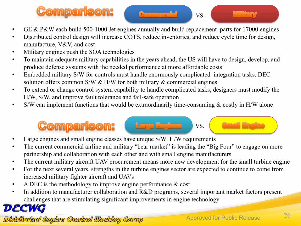
• GE & P&W each build 500-1000 Jet engines annually and build replacement parts for 17000 engines• Distributed control design will increase COTS, reduce inventories, and reduce cycle time for design,
manufacture, V&V, and cost• Military engines push the SOA technologies• To maintain adequate military capabilities in the years ahead, the US will have to design, develop, and
produce defense systems with the needed performance at more affordable costs• Embedded military S/W for controls must handle enormously complicated integration tasks. DEC
solution offers common S/W & H/W for both military & commercial engines• To extend or change control system capability to handle complicated tasks, designers must modify the
H/W, S/W, and improve fault tolerance and fail-safe operation• S/W can implement functions that would be extraordinarily time-consuming & costly in H/W alone
VS.
• Large engines and small engine classes have unique S/W H/W requirements• The current commercial airline and military “bear market” is leading the “Big Four” to engage on more
partnership and collaboration with each other and with small engine manufacturers• The current military aircraft UAV procurement means more new development for the small turbine engine • For the next several years, strengths in the turbine engines sector are expected to continue to come from
increased military fighter aircraft and UAVs• A DEC is the methodology to improve engine performance & cost• In addition to manufacturer collaboration and R&D programs, several important market factors present
challenges that are stimulating significant improvements in engine technology
VS.
Approved for Public Release 27Approved for Public Release 27
VS.
• Military demand is growing for FADEC & control systems with expert systems embedded in the S/W for fault tolerance.
• Civilian demand has spurred rapid technological progress for commercial aircraft.• Escalating procurement and fuel costs will stimulate the DoD to leverage
commercial FADECs & control systems S/W & H/W. • Modular / Universal/Distributed design can reduce development time and cost.
S/W could offer baseline for military-qualified FADECs. • To promote dual use, the services must recognize the similarities between
commercial applications & military needs; too often, they focus on the differences
• Avionics has been the chief success story in transferring military S/W and hardware to civil sector. Through VAATE and SBIR funding a lot of technologies has been transferred to commercial avionics.
• Modeling & real-time SIMULATION can reduce integration cost for both commercial and military engine controls
• Technology transfer also occurs from both commercial & military programs
Approved for Public Release 28Approved for Public Release 28
Engine: Pays Cost of FADEC Development/ProductionFADEC Weight / Size Impacts Engine Design
3rd Party Service Providers: Pay for FADEC Repair & Impact to Airline
Aircraft/Engine Purchaser: Responsible for FADEC Repair Cost Aircraft Operator: Impact of Failures i.e. Delays/CancellationsLine Maintainer: Labor/Materials FADEC Troubleshooting & Repair
Approved for Public Release 29Approved for Public Release 29
Weighting of Values Vary By Engine Application
Purchase Cost / WeightIncreasingly Valued As Engine Size Decreases
Control System As Percentage of Total Engine Weight/Cost
Engine Manufacturer ValuesOften Transfer to Military Customers
DoD Owns Engine Design – Often Responsible for Development / Production Costs
ReliabilityEven More Critical for Smaller Airline FleetsFewer Aircraft Means Fewer Options When One is Down for Maintenance
Approved for Public Release 30Approved for Public Release 30
How Can FADEC Impact Customer Value?
Reduce Overall Control System WeightConsider Electronics, Power Supplies, Housings, Connectors, Harnesses, etc.
Enable Reuse and Upgradability of FADEC ComponentsProvide Head Start on FADEC For New Applications
Improved Control System Component ReliabilityRobustness Against Steady and Cyclical Temperature and Vibrational Effects
Easier Control System Troubleshooting and RepairReduced Training and Labor Hours via Automation
Approved for Public Release 3131
Bill RhodenHamilton-Sundstrand
Casey CarterBAE Systems
Approved for Public Release 32Approved for Public Release 32
Considerations for Power Distribution in a Distributed System
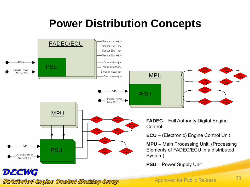
• Currently in most centralized engine control systems the Power Supply Unit (PSU) is embedded into the FADEC or ECU
• PSU volumes can account for 25% to 40% of the total FADEC/ECU volume
• Power is classically supplied to the ECU by either an 115VAC or 28VDC aircraft input or from the Permanent Magnet Alternator (PMA)
• Energy harvesting for remote modules currently not seen as robustor reliable enough for a critical engine control system, therefore a dedicated PSU should be used to power the remote modules
• The power requirements for remote modules may vary depending on function/capabilities of the module (e.g. actuator driver vs. simple smart sensor)
Approved for Public Release 33Approved for Public Release 33
Power Distribution Concepts
FADEC – Full Authority Digital Engine Control
ECU – (Electronic) Engine Control Unit
MPU – Main Processing Unit, (Processing Elements of FADEC/ECU in a distributed System)
PSU – Power Supply Unit
Approved for Public Release 34Approved for Public Release 34
• Can a Commercial Off the Shelf (COTS) serial bus be used for an Engine Area Network (EAN) solution that supports an open distributed control architecture?
• Several busses exist from the industrial, automotive and aerospace control market areas. Which would be the best fit?
• Need to, as an industry, define the required performancerequirements based on several distributed control topologies
• Key selection criteria should include:– Bandwidth– Compatibly with current high temperature electronics capability– Predictable communication response times between master and remote
Approved for Public Release 35Approved for Public Release 35
Engine Area Network Selection Conclusions
• Does any one bus meet all of the selection criteria?• Published studies and customer responses have shown a desire for a
multi-drop bus topology (as opposed to star, ring, etc.) since it has been theorized to optimize cabling weight savings
• The current availability of High Temperature Electronics (serial bus physical and logical devices) is seen as the largest divider for a EANbus selection
• Identification, detection and handling of faults also needs to be considered
• DECWG partners should work together to define a single bus protocol and physical layer options that support open distributed engine control architectures
Are there High Temperature Electronics to support the bus physical layers?
Approved for Public Release 36Approved for Public Release 36
A Current View of High Temperature Electronics Market Space
• High Temperate Electronics is currently a niche market with a limited list of available components which are usually costly and with limitedlife and reliability… but evolving quickly
• Currently aligned to drilling or “down hole” application requirements that do not necessarily overlay with avionics requirements– Focused on remote sensing oriented and not actuation
• Some transfer of radiation hardened technology to high temperature• Published avionics quality reliability data
– Data is currently lacking even for some high temperature components– SEU and SEL Data availability
• Avionics component life and pricing needs are not met with current offerings
• Strongly suggest that DECWG work with electronics vendors and start to compile a list/library of available components to support future high temperature distributed controls development
What is the avionics that engine and aircraft operators are willing to live with for the price to improve efficiency and flexibility?
Approved for Public Release 37Approved for Public Release 37
High Temperature Electronics Needs• Predicted temperature range limits: -55°C to > +200°C
– This reflects what is currently available with SOI technology– Estimate modules would be exposed to max temps 80-90% of life – Studies from engine OEMs could expand/contract temperature and duty cycle
estimates• Longer Life and Reliability
– Current engine controls have long life requirements• Competitive Cost
– What are the sustainment cost or total cost of ownership benefits of a distributed system compared to a centralized system?
– Current component cost is approximately 10 - 20 times that of equivalent military temperature parts
• Long Term Component Availability– Approximately 20 years– Can high temperature device vendors manage product obsolescence better than
current commercial devices to decrease life cycle costs?• Example Component Needs
– Larger FPGAs, Processors, Micro-Controllers– Serial Bus Logic Layer and Physical Layer Controllers– ADC and DAC– PWB
Approved for Public Release 38Approved for Public Release 38
FAR Part 33 Certification Rules• Section 33-28 Electrical & Electronic Engine Control
Systems– Loss of Aircraft Power or Data – No unacceptable change in
thrust• Channel 1 to Channel 2• One control mode to another• Primary to Back-up control
– Single-Point or Probable Combination Failures– Software Design & Implementation to prevent errors
• Section 33-75 Safety Analysis– Hazardous (10-7 to 10-9) and Major Engine Effects (10-5 to 10-7)– Thrust changes– Erroneous Data Transmissions– Surge / Stall
• Section 33-83 Vibration Tests
Approved for Public Release 39Approved for Public Release 39
FAR Part 33 Certification Rules
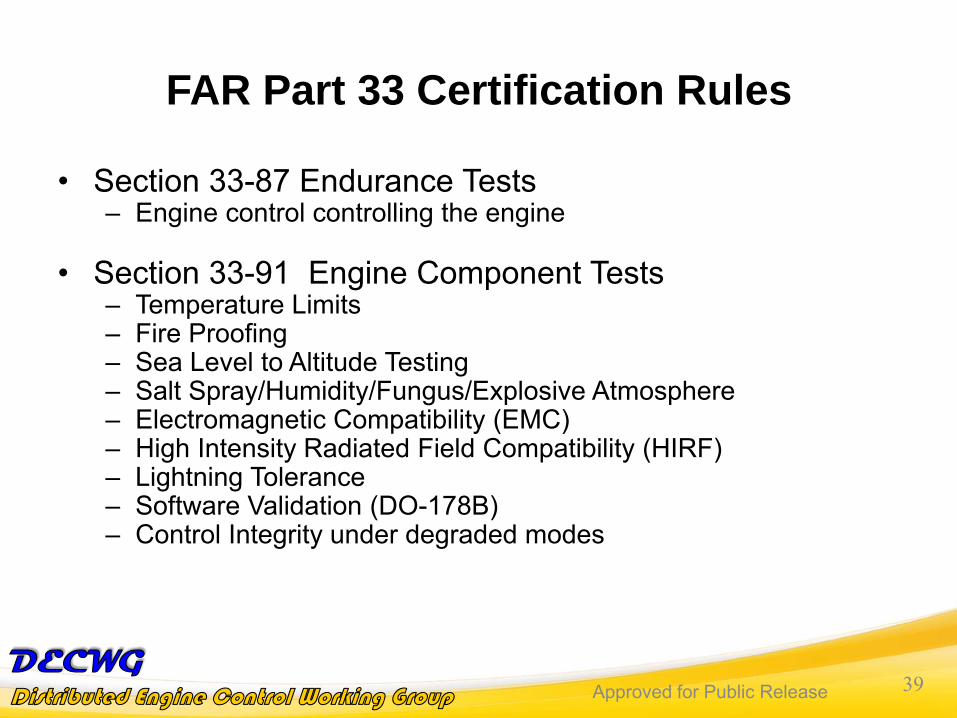
• Section 33-87 Endurance Tests– Engine control controlling the engine
• Section 33-91 Engine Component Tests– Temperature Limits– Fire Proofing– Sea Level to Altitude Testing– Salt Spray/Humidity/Fungus/Explosive Atmosphere– Electromagnetic Compatibility (EMC)– High Intensity Radiated Field Compatibility (HIRF)– Lightning Tolerance– Software Validation (DO-178B)– Control Integrity under degraded modes
Approved for Public Release 40Approved for Public Release 40
Considerations for Certifying a Distributed Engine Control Architecture
• Different from the Norm– Failure Modes
• Loss of Power• Single Point/Multi Point
Failures• Software
– Unintended Interactions• Latency• Data Integrity
– Increased Connections• Reliability
– Potential Harsher Environment
• Smart nodes in hot section– Communications
Protocol(s)• Coordination of multiple
protocols?– EMI/HIRF/Lightning
Susceptibility– Software Validation (DO-
178B)– Dispatchable failures?
As Good As Current Architecture
Approved for Public Release 4141
Gary HunterNASA Glenn Research Center
Dewey BensonHoneywell
Approved for Public Release 42Approved for Public Release 42
High Temperature Electronics for Distributed Controls
Issues• High temp electronics have been the “show stopper” in past attempts
• Lack of available parts to make a full distributed node• Difficulty of getting non-volatile memory to work at high temp• Cost of solutions
• User community wants the same cost as low temp electronics• Compact size desired
Trade-offs• Standard silicon solutions versus Silicon-On-Insulator (or Sapphire)
or SiC• Build up solutions from discrete parts or develop custom chips
(ASICs)• Temperature capability versus reliability
Specific application needs could dictate different solutions
Approved for Public Release 43Approved for Public Release 43
It Starts With The Base Silicon Technology!
Standard Silicon versus Silicon On Insulator• Buried SiO2 (SOI) Insulating Layer
Provides:- High Temperature Operation 225 C continuous
and excursions to 300 C- Ultra High Reliability- 30% To 40% Faster Circuits- 30% To 40% Lower Power- Better Isolation For Mixed Signal ASIC- Improved Sensor Accuracy And Stability
• SOI wafer cost is higher• Process complexity of Bulk Silicon
and SOI is similar• Low leakage is key to non-volatile
memory
Approved for Public Release 44Approved for Public Release 44
• Silicon Solution: Physically greater separation between junctions• SOI Solution: Glass or Sapphire provides higher dielectric. i.e. lower
leakage
• Issue 2: MOS transistors leak!Sub-threshold conduction increases with temperatureStandard commercial SOI processes leak badly above 150°C
• Solution: Increase transistor threshold voltage implants to compensate
• Issue 3: Aluminum Inter-connects “move”!! (electromigration)Strong function of temperature and current
• Solution: Reduce average current density to gain high-temp. reliability• Solution: Increase interconnect area Bigger footprint
Cost of SOI trades against lower leakage for similar gate spacing
Problems With Electronics At High Temperature
Approved for Public Release 45Approved for Public Release 45
High Temperature Standard Silicon DesignExample: Texas Insturments 24-bit A-to-D (ADS1278 & ADS1278-HT)
• High reliability part design • Same die for 105C and 210C parts• Screened for higher 210C temp range
Normal Hi Rel Part• -40 to +105 C• Plastic package• Cost:
High Temperature Part• -55 to +210 C• Die only• Cost: $5 $15$10X X X
Act Now! Special Offer!
$125 per TI website
$24 Std parts $4 - $7
Low Temp (85C) DesignDie area ~1/2 of Hi Rel
ADS1217/1218
Hi Rel Design
Approved for Public Release 46Approved for Public Release 46
High Temperature Silicon DesignTexas Instruments High Temperature Parts Offerings
High Temperature Parts• -55 to +210 C• Ceramic surface mountor die only• Minimum 1000 hrs life
Approved for Public Release 47Approved for Public Release 47
Notes:1. See datasheet for absolute maximum and minimum recommended operating conditions.2. Silicon operating life design goal is 10 years at 110 C junction temperature.3. Courtesy Texas Instruments
High Temperature Silicon Design
200C = 3200 hrs
Approved for Public Release 48Approved for Public Release 48
SOI Operating Time vs. Temp96,000 hours operation at 200 C, 1% Failure Rate
225,000 hours MTBF
TEMPERATURE (°C)
YEARS
0
1
10
100
150 170 190 210 230 250 270 290 310 330 350
AlCu:1mA/µm2
AlCu: .5mA/µm2
Time for 1%of the parts
to fail
Commercial Parts: Est. for 5 mA/µm2
Operation Based on Temperature AND Time!
= 43,800 hrs at 1% failure rate= 100,000 hrs MTBF
200 C
225 C
Approved for Public Release 49Approved for Public Release 49
2 Million Device Hours Worth Of Life Test Data
Standard Catalog Products:• HTOP01 Dual Precision Op Amp • HT1104 Quad Operational Amplifier• HT1204 Quad Analog Switch• HTPLREG Voltage Regulators • HT83C51 8-bit Micro Controller• HT6256 256Kbit SRAM (32K x 8)• HT506 Analog Multiplexer (16:1)• HT507 Analog Multiplexer (8:2)• HTCCG Crystal Clock Generator• HTNFET N-channel power FET
Custom Capabilities:• Gate Arrays• MCM (Multi-Chip Modules)• High Temperature Design Services
Products in Development:• HTA/D Converter (12 and 18 bit)• HTEEPROM• HTFPGA• Reconfigurable Processor for Data Acquisition (RPDA)
High Temperature SOI Part Availability
Parts portfolio expansion is slow & EXPENSIVE!
Key to flexibility: Non-volatile memory not perfect (still needs occasional refresh):
Approved for Public Release 50Approved for Public Release 50
First Attempt At High Temperature Electronics
• Tested at 200C• Microcontroller w/ BIT• 1553 Interface
Biggest Negatives – Cost & Lack of Non-Volatile Memory
High Temperature Servoactuator Electronic Interface Unit (EIU)Circa 1999, Funded by Air Force Research Labs
• PWM Torque Motor Drive• LVDT Interface• 0.57 lbs• 1.2 x 2.3 x 3.4 inches
Approved for Public Release 51Approved for Public Release 51
Will never overcome high development costs without collaboration
Take-AwaysHow To Get The Most Out Of High Temperature ElectronicsIssues• High temp electronics will be more expensive:
• If show-stopper, might as well stop now • Each part is expensive, almost independent of part complexity• Part cost driven by design cost, process development effort, and set-up costs• Up-front costs too high for a single supplier to carry and hope to make a profit.
Industry response needed:• Users need to define a cost point that still yields benefits• Need consensus design for high temp nodes, then develop accurate estimate• Incorporate into as few parts as possible to minimize cost Custom ASICs• Users, suppliers, and gov’t share cost to develop high temp nodes • Shared access to resulting products
Approved for Public Release 52Approved for Public Release 52
High Temperature Electronics for Distributed ControlsIssues• ENGINE MANUFACTURES FACE DEMANDS TO
MEET THE INCREASING REQUIREMENTS FOR REDUCED EMISSIONS, REDUCED FUEL BURN, AND INCREASED SAFETY
• TO MEET THESE NEEDS THE INCLUSION OF DISTRIBUTED INTELLIGENCE INTO THE ENGINE DESIGN AND OPERATION BECOMES NECESSARY
• HOWEVER, ENGINES ARE HARSH ENVIRONMENTS. SPECIAL CHALLENGES INCLUDE:
OPERATION IN HIGH TEMPERATURE, HARSH ENVIRONMENTS WITH POTENTIALLY HIGH VIBRATIONMINIMAL SIZE, WEIGHT, AND POWER CONSUMPTION FAILURE MECHANISMS WHICH DO NOT SHUT DOWN THE VEHICLE
HARSH ENVIRONMENT TECHNOLOGIES NEEDED FOR NEXT GENERATION ENGINES
Approved for Public Release 53Approved for Public Release 53
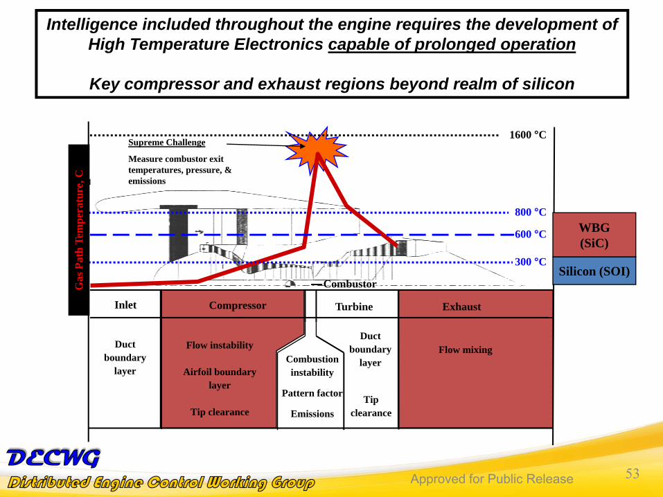
Intelligence included throughout the engine requires the development of High Temperature Electronics capable of prolonged operation
Key compressor and exhaust regions beyond realm of siliconG
as P
ath
Tem
pera
ture
, C
600 °C
Silicon (SOI)
WBG(SiC)
Approved for Public Release 54Approved for Public Release 54
LONG TERM VISIONAVIONICS ARCHITECTURE VISION USING DISTRIBUTED SMART SYSTEM
• BASED ON INTELLIGENCE RESIDING WITHIN EACH DISTRIBUTED SMART SYSTEM CONTRIBUTING TO THE INTELLIGENCE OF THE COMPLETE SYSTEM
• ENABLE INTERNAL SYSTEMS TO MONITOR COMPONENT CONDITIONS, ANALYZE INCOMING DATA, AND MODIFY OPERATING PARAMETERS TO OPTIMIZE SYSTEM OPERATIONS TO ACHIEVE IMPROVED PERFORMANCE/RELIABILITY
• ELIMINATE VEHICLE SYSTEMS THAT REQUIRE INTENSE HUMAN INTERVENTION
• SMART SYSTEM TECHNOLOGY INCLUSION OFTEN PROBLEMATIC IN AERONAUTICVEHICLE SYSTEMS
“TURN AND BURN”/MAKE IT SIMPLE
LEGACY SYSTEMS
CUSTOMER ACCEPTANCE
LONG-TERM VS SHORT TERM
CONSIDERATIONS
LIMIT BURDEN ON VEHICLE
Approved for Public Release 55Approved for Public Release 55
SMART DISTRBUTED SYSTEM DEVELOPMENT• THIS IS NOT JUST AN ELECTRONICS, SENSOR, ACTUATOR, COMMUNICATION, OR
POWER ISSUE BUT AN INTEGRATRED SYSTEM ISSUE• COMPLETE MICROSYSTEM PACKAGE IS LONG-TERM OBJECTIVE• IF A DISTRIBUTED SYSTEM IS GOING TO BE EFFECTIVE, THEN IT SHOULD BE
APPLIED WHERE IT IS NEEDED, NOT JUST WHERE IT IS CONVENIENT LIMITED ON-BOARD HARSH ENVIRONMENTS SYSTEMS LEAVING SIGNIFICANT AREAS OF THE PROPULSION SYSTEM UNMONITORED FOR ENGINE APPLICATIONS, HARSH ENVIRONMENT MICROSYSTEMS NECESSARY
SENSORS
ACTUATORS
Communication
Power
Electrical/Optical
Phys
ical
/Che
mic
al S
igna
l
Mec
hani
cal/D
ispl
ay/E
lect
rical
Po
wer
Analog-Digital-AnalogSignal Processing
Microsystem Block Diagram
Approved for Public Release 56Approved for Public Release 56
• DESIGN SMART SYSTEM FOR THE NEEDS OF APPLICATIONDeliverables/budget/time frame are typically application and vehicle dependent. Smart systems should be tailored for the specific application. Ideally, they should be included at the beginning of the design process rather than as an afterthought
• “LICK AND STICK” TECHNOLOGY (EASE OF APPLICATION) Micro/nano fabrication to enable multipoint inclusion of sensors, actuators, electronics, and communication throughout the vehicle without significantly increasing size, weight, and power consumption. Multifunctional, adaptable technology included.
• RELIABILITYUsers must be able to believe the data reported by these systems and have trust in the ability of the system to respond to changing situations e.g. decreasing sensors should be viewed as decreasing the available information flow about a vehicle. Inclusion of intelligence more likely to occur if it can be trusted.
• REDUNDANCY AND CROSS-CORRELATION If the Smart systems are easy to install, reliable, and do not increase weight complexity, the application of a large number is not problematic allowing redundant systems, e.g. sensors spread throughout the vehicle.
• SUPPORTING TECHNOLOGY OFTEN DETERMINE SUCCESS OF SYSTEM• Packaging, communication infrastructure, lead wires, mounting constraint etc. often
dominant in whether a system can be successfully implemented.
OVERCOMING RESISTANCE TO SMART SYSTEM IMPLEMENTATION
Approved for Public Release 57Approved for Public Release 57
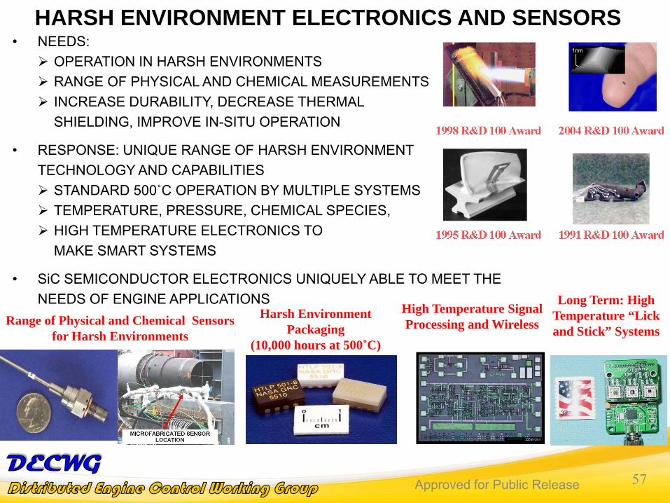
• NEEDS:OPERATION IN HARSH ENVIRONMENTS RANGE OF PHYSICAL AND CHEMICAL MEASUREMENTSINCREASE DURABILITY, DECREASE THERMAL SHIELDING, IMPROVE IN-SITU OPERATION
• RESPONSE: UNIQUE RANGE OF HARSH ENVIRONMENT TECHNOLOGY AND CAPABILITIES
STANDARD 500˚C OPERATION BY MULTIPLE SYSTEMSTEMPERATURE, PRESSURE, CHEMICAL SPECIES, HIGH TEMPERATURE ELECTRONICS TO MAKE SMART SYSTEMS
• SiC SEMICONDUCTOR ELECTRONICS UNIQUELY ABLE TO MEET THE NEEDS OF ENGINE APPLICATIONS
Harsh Environment Packaging
(10,000 hours at 500˚C)
Range of Physical and Chemical Sensors for Harsh Environments
High Temperature Signal Processing and Wireless
Long Term: High Temperature “Lick and Stick” Systems
HARSH ENVIRONMENT ELECTRONICS AND SENSORS
Approved for Public Release 58Approved for Public Release 58
NASA Glenn Discrete SiC JFET Transistors: First to Surpass 10,000 Hours of Stable Electrical Operation at 500°C
Current-voltage characteristics are very good and stable after 4000 hours• Enables realization of analog integrated circuits (amplifiers, oscillators)• Excellent turn-off characteristics, ON to OFF current ratio• Enables realization of digital circuits.
Less than 10% change occurs during
10000 hours operation at 500°C.
- Most silicon transistor spec sheets list larger parameter
variations.
Approved for Public Release 59Approved for Public Release 59
NASA Glenn Silicon Carbide Differential AmplifierWorld’s First Semiconductor IC to Surpass
5000 Hours of Electrical Operation at 500 °CDemonstrates CRITICAL ability to interconnect transistors and other components (resistors) in a small area on a single SiC chip to form useful integrated circuits that are durable at 500 °C.
100 um
Optical micrograph of demonstration amplifier circuit before packaging
Test waveforms at 500 °C
2 transistors and 3 resistors integrated into less than half a square millimeter.
Single-metal level interconnect. Less than 5% change in
operating characteristics during 5000 hours of 500 °C operation.
Approved for Public Release 60Approved for Public Release 60
NASA Glenn SiC JFET NOR Gate IC
Probe-Test Photo
World’s First Semiconductor Digital IC toSurpass 3000 hours of 500 ºC Operation
Digital Inverter Test Waveforms
With proper design, circuits function well over broad temperature rangeOperation from 25 C to 500 C with no change to supply or logic voltages!
Approved for Public Release 61Approved for Public Release 61
SIGNIFICANCE OF RECENT ELECTRONICS RESULTSTHE BASIC HARDWARE TOOLS FOR HIGH TEMPERATURE
DATA PROCESSING HAVE BEEN FABRICATED♦ THESE RESULTS HAVE BEEN THE SUBJECT OF A HIGH LEVEL OF VISIBILITY E.G.
NASA TOP 10 DISCOVERY STORIES FOR 2007
♦ DURABLE HIGH TEMPERATURE IC’S WILL ENABLE IMPORTANT NEW CAPABILITY
Enabled by fundamental electronic materials research.World record IC durability at 500 ºC (> 400-fold improvement).Inherently up-scalable to high circuit complexity while remaining physically small.
♦ THIS DEMONSTRATION SHOWS THAT IT IS NOW POSSIBLE TO CONSTRUCT MORE COMPLEX CIRCUITS OPERATING AT 500°C AND MINIATURIZED.
♦ LOGIC GATES GENERATE FLIP-FLOPS THAT CAN GENERATE STATE-MACHINES TO ENABLE:
Creation Of Control Electronics For An “Intelligent” Fixed Or Mobile Agent
The Configuration Of Intelligent Data Transmission Methods Allowing For Unambiguous Demodulation Of Signals Uniquely Associated With Each Sensor/Transmitter In A Network.
Approved for Public Release 62Approved for Public Release 62
OBJECTIVE : TO MOVE TOWARD HIGHER DEGREES OF COMPLEXITY ALLOWING HARSH ENVIRONMENT SMART SENSOR SYSTEMS
Example System Demonstration: Milestone: Demonstrate High Temperature Sensing, Wireless Communication, and
Power Scavenging for Propulsion Health Management 8/30/2011Metric: Demonstrate integrated self powered wireless sensor system at 500˚C
with data transmission with operational life of at least 1 hr
World Record High Temperature Electronics
Device Operation
Allow Sensor Implementation by Eliminating Wires
High Temperature RF Components
Energy HarvestingThin Film
Thermoelectrics
�������� ��������������������������������������
Significant wiring exists with present
sensor systems
Approved for Public Release 63Approved for Public Release 63
POTENTIALLY THREE STAGES OF INCLUSION OF ELECTRONICS, SENSORS, ACTUATORS, AND
CONTROL LOGIC:
1) SYSTEM DEVELOPMENT AND GROUND TESTING WHERE THE SENSORPROVIDES INFORMATION ON THE STATE OF A SYSTEM THAT DOES NOT FLY.THIS INFORMATION USED FOR THE DESIGN AND ADVANCED MODELING OFSYSTEMS THAT ARE USED IN FLIGHT
2) VEHICLE HEALTH MONITORING (VHM) WHICH INVOLVES THE LONG-TERMMONITORING OF A SYSTEM IN OPERATION TO DETERMINE THE HEALTH OFTHE VEHICLE SYSTEM (E.G., IS THE ENGINE INCREASING FUEL BURN ORINCREASING EMISSIONS). THIS INFORMATION USED TO CHANGE ENGINEPARAMETERS TO IMPROVE PERFORMANCE OR IMPROVE GROUNDMAINTENANCE
3) ACTIVE CONTROL OF THE VEHICLE IN A FEEDBACK MODE WHEREINFORMATION FROM A SENSOR AND POSSIBLY ACCOMPANYINGELECTRONICS IS USED TO CHANGE A SYSTEM PARAMETER IN REAL-TIME
Approved for Public Release 64Approved for Public Release 64
POSSIBLE PATH TO TECHNOLOGY IMPLEMENTATION♦ NASA CAN DEMONSTRATE THE BASIC CAPABILITIES; COMMERCIAL TECHNOLOGY
IMPLEMENTATION DRIVEN BY INDUSTRY♦ TYPICAL DRIVERS
CHANGE IN MARKET CONDITIONSGOVERNMENT REGULATIONS“IDEAL” APPLICATION
♦ NASA IS ACTIVELY DEVELOPING THE CORE TECHNOLOGY FOR FUTURE HIGH TEMPERATURE SMART SENSOR IMPLEMENTATION
BASIC APPROACH TARGETED TO PROVIDE A PRODUCT THAT INDUSTRY WOULD USE: COMPLETE SYSTEM, SMART, MULTIFUNCTIONAL, RELIABLE, EASY-TO-USEPARALLEL PATH APPROACH TOWARDS TECHNOLOGY ACCEPTANCE
• DEMONSTRATE INCREASING CAPABLE TECHNOLOGY IN RELEVANT CONDITIONS
• FURTHER FUNDAMENTAL DEVELOPMENT (EVEN DOWN TO THE BASIC MATERIAL LEVEL) OF THE CORE TECHNOLOGY TOWARDS INCREASING COMPLEXITY AND CAPABILITY. KEY TO DECREASED COSTS
♦ MANUFACTURABILITY AND COSTS ARE DRIVING FACTORS IN IMPLEMENTATIONBASIC PRINCIPLES BEING SHOWN WITH SIC JFET TECHNOLOGYSIGNIFICANT EFFORT TO IMPROVE SIC SEMICONDUCTOR MATERIAL QUALITY
• WOULD POTENTIALLY ALLOW USE OF MOSFET CIRCUIT DESIGNS• SIGNIFICANT LEVERAGING OF EXISTING SILICON-BASED PROCESSING
AND CIRCUITS
Approved for Public Release 65Approved for Public Release 65
Adaptable Core Harsh Environment Technology Being Developed and Matured to Meet the Needs of Future Intelligent Engines
Take-AwaysISSUES• SMALLER, SMARTER, DISTRIBUTED SYSTEMS NEEDED FOR NEXT GENERATION
ENGINES• LIMITED HARSH ENVIRONMENT TECHNOLOGIES AVAILABLE• COMPLETE SYSTEM PROBLEM: ELECTRONICS AS WELL AS POWER,
COMMUNICATIONS, SENSORS, AND SUPPORTING TECHNOLOGIES• HIGHER TEMPERATURE APPLICATIONS BEYOND THE CAPABILITIES OF SI OR SOI
ELECTRONICS
NASA DEVELOPING CORE TECHNOLOGIES FOR FUTURE SMART SYSTEMS• WORLD RECORD SIC ELECTRONICS DEMONSTRATED• MOVING TOWARDS MICROSYSTEM TECHNOLOGY WITH INTEGRATED ELECTRONICS,
SENSORS, POWER, AND COMMUNICATION• TECHNOLOGY CAN BE IMPLEMENTED WITH INCREASING CONFIDENCE IN SYSTEMS,
EASE OF USE, AND DEMONSTRATIONS IN THE FIELD• COST CAN COME DOWN WITH INCREASING CIRCUIT CAPABILITY AND MATERIAL
MATURITY COMBINED WITH TRANSITION FROM JFET TO MOS TECHNOLOGY.
Approved for Public Release 6666
Derek WeberInprox Technology
Approved for Public Release 67Approved for Public Release 67
Small Business Participation
INDEX SLIDE
• Market Challenges• FADEC Architecture and Small
Businesses• DEC Architecture and Small Businesses• Market Needs
Approved for Public Release 68Approved for Public Release 68
Market ChallengesAerospace Market Challenges for Small Businesses
• Access: availability of funding & commercialization support pathways• Timeline 5-10 yrs. / 20yr. FADEC / Upgrades need major ‘buy on’• Who is the “real” customer in this market?• Is there third party technology Interest? Manufacturing or Licensing… • Risk Mitigation vs. New Technology or New Suppliers (QA/QC)
• Strong argument that DEC architecture supports Small Business Point of View (POV)
• With FADEC• Fixed Architecture/Centralized• All products/technology must fit existing envelopes and I/O
• hardware and electronics
Resource Burden in Time & Money
Approved for Public Release 69Approved for Public Release 69
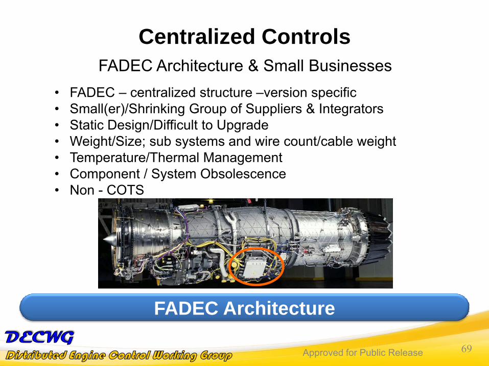
Centralized ControlsFADEC Architecture & Small Businesses
• FADEC – centralized structure –version specific• Small(er)/Shrinking Group of Suppliers & Integrators• Static Design/Difficult to Upgrade • Weight/Size; sub systems and wire count/cable weight• Temperature/Thermal Management• Component / System Obsolescence • Non - COTS
FADEC Architecture
Approved for Public Release 70Approved for Public Release 70
De-Centralized Controls
DEC Architecture Generally Supports Small Businesses POV
DEC Architecture & Small Businesses• Modularity
• Creates new opportunities to build niche markets• Expansion of current supplier base
• New Suppliers/New Technologies • Open Standards• Cost & Time line Reduction• Tapping components from commercial or automotive electronics • Greater ability to offer new technology faster• DEC: reduced design time, manufacture time, integration and test
costs: through functional modularity and standardization --- common building blocks within engine systems and across engine platforms –helps primes, suppliers, and certification AND Small Businesses.
Approved for Public Release 71Approved for Public Release 71
Market NeedsAerospace Market Needs & Small Businesses
• High Temperature Electronics• ( < 250C) (SOI): limited part selection – max below engine range• ( < 500C) (SiC): very few commercial parts• Affordability? Life Cycle Costs?
• Busses: from industrial, automotive or the aerospace control market
• Standards exist, however not in engine applications• Which One?
What Materials, Markets and Standards?
Approved for Public Release 7272
Dennis CulleyNASA Glenn Research Center
Approved for Public Release 73Approved for Public Release 73
Are control systems keeping pace with turbine engine system needs? (regardless of the vision)
Short answer: yes, but…• FADEC implementation time is pacing engine development
– Intense pressure to reduce weight and cost• Control system upgrade costs can equal original design costs
– Complexity and cost deters new technology insertion– Electronics obsolescence (determined by commercial markets) is
unpredictable and uncontrollable• Engine system advancements are increasing the physical burden on
control system electronics– Reduced capacity for heat extraction– Reduced temperature margin (reliability) vs. weight of thermal control– Increasing need for higher density packaging to fit in shrinking envelope
Approved for Public Release 74Approved for Public Release 74
What technologies are required for existing and future engine control systems?
• Communication Network– Distribution of control functions requires digital communications– Need for understanding the requirements for control and PHM
• Power Distribution– Distributed control functions require distributed power– Needs of control elements vary widely in current and voltage
• High Temperature Electronics– Reliable electronics require sufficient thermal margin
• Add weight for thermal control, OR• Increase the operational temperature of the electronics
• Flight Certification– Cost benefit of distributed control is contingent on modular certification– Distributed systems are controlled by interface definitions; standard,
well-defined interfaces are required
Approved for Public Release 75Approved for Public Release 75
Why / How should engine control systems use emerging electronics and control technologies?
• High power control law processing remains in the realm of commercial electronics for the foreseeable future – we must be able to use it.
• The modularity of distributed control systems have a huge potential in terms of design flexibility, life cycle cost reduction, and performance enhancement.
• High temperature electronics are necessary to enable on-engine control functionality without additional weight for thermal control
• High temperature electronics will not be available unless…– Component/Functional needs are collaboratively defined– Development costs are collaboratively shared
Approved for Public Release 76Approved for Public Release 76
Go – Forward PlanA series of workshops will be planned over the next year to address the four technology challenge areas defined in this presentation
1. Digital communication networks for turbine engine control systems
2. Power distribution for distributed turbine engine control systems
3. High temperature electronics for turbine engine control applications
4. Modular flight certification for distributed turbine engine control systems
Please provide your contact information to the session chair if you are interested in participating in these workshops – US citizens only please.
Dennis E. Culley dennis.e.culley@ nasa.gov (216) 433-3797
Approved for Public Release 77Approved for Public Release 77