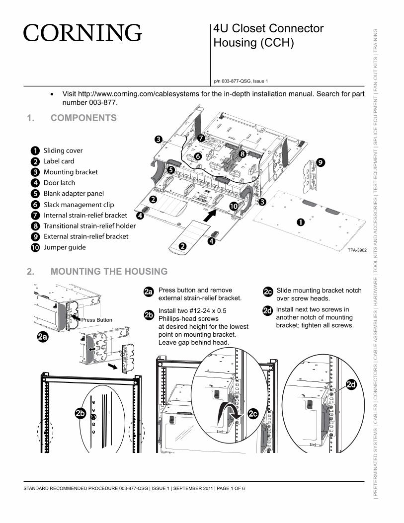
p/n 003-877-QSG, Issue 1 STANDARD RECOMMENDED PROCEDURE 003-877-QSG | ISSUE 1 | SEPTEMBER 2011 | PAGE 1 OF 6 | PRETERMINATED SYSTEMS | CABLES | CONNECTORS | CABLE ASSEMBLIES | HARDWARE | TOOL KITS AND ACCESSORIES | TEST EQUIPMENT | SPLICE EQUIPMENT | FAN-OUT KITS | TRAINING 4U Closet Connector Housing (CCH) • Visit http://www.corning.com/cablesystems for the in-depth installation manual. Search for part number 003-877. 1. COMPONENTS 2. MOUNTING THE HOUSING 1 Sliding cover 2 3 Mounting bracket 4 Door latch 5 Blank adapter panel 8 Internal strain-relief bracket 9 Slack management clip 10 External strain-relief bracket Jumper guide 7 6 Label card Transitional strain-relief holder 2 1 3 4 6 7 5 3 8 9 10 4 TPA-3902 2 2c 2b 2d 2a Install two #12-24 x 0.5 Phillips-head screws at desired height for the lowest point on mounting bracket. Leave gap behind head. Press button and remove external strain-relief bracket. Slide mounting bracket notch over screw heads. Install next two screws in another notch of mounting bracket; tighten all screws. Press Button 2a 2b 2d 2c
Transcript
p/n 003-877-QSG, Issue 1
STANDARD RECOMMENDED PROCEDURE 003-877-QSG | ISSUE 1 | September 2011 | PAGE 1 OF 6
| PR
ETE
RM
INAT
ED
SY
STE
MS
| C
AB
LES
| C
ON
NE
CTO
RS
| C
Ab
Le A
SS
em
bLI
eS
| H
AR
DW
AR
E |
TOO
L K
ITS
AN
D A
CC
ES
SO
RIE
S |
TES
T E
QU
IPM
EN
T | S
PLI
CE
EQ
UIP
ME
NT
| FA
N-O
UT
KIT
S |
TRA
ININ
G4U Closet Connector Housing (CCH)
• Visit http://www.corning.com/cablesystems for the in-depth installation manual. Search for part number 003-877.
1. Components
2. mounting the housing
1 Sliding cover
23 Mounting bracket
4 Door latch
5 Blank adapter panel
8Internal strain-relief bracket
9
Slack management clip
10
External strain-relief bracketJumper guide
76
Label card
Transitional strain-relief holder
2
1
3
4
6
7
5
3
89
10
4TPA-3902
2
2c
2b 2d
2a
Install two #12-24 x 0.5 Phillips-head screwsat desired height for the lowestpoint on mounting bracket.Leave gap behind head.
Press button and remove external strain-relief bracket.
Slide mounting bracket notchover screw heads.
Install next two screws inanother notch of mounting bracket; tighten all screws.
TPA-3903
Press Button
2a
2b
2d
2c
STANDARD RECOMMENDED PROCEDURE 003-877-QSG | ISSUE 1 | September 2011 | PAGE 2 OF 6
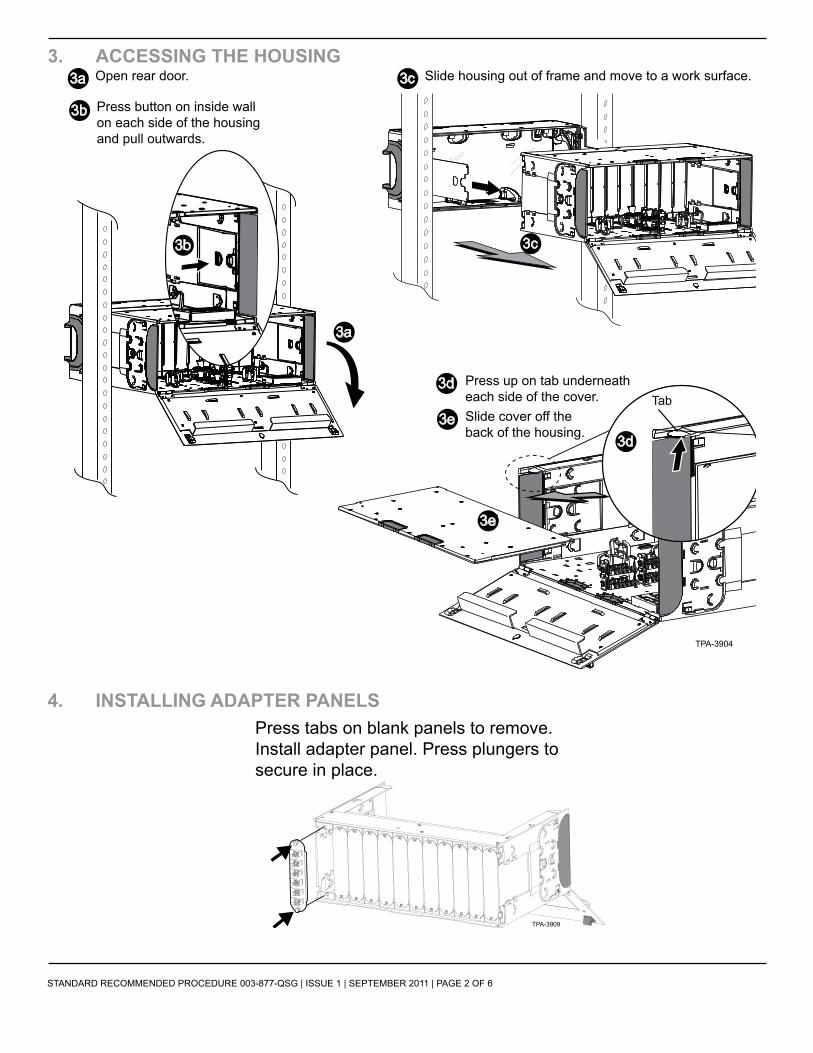
3. ACCessing the housing
4. instAlling AdApter pAnels
3a
3a
Open rear door.
3b
3d
3e
Press up on tab underneath each side of the cover.
TPA-3904
Press button on inside wallon each side of the housingand pull outwards.
TabSlide cover off the back of the housing.
3b
3c
3c
Slide housing out of frame and move to a work surface.
3d
3e
Press tabs on blank panels to remove.Install adapter panel. Press plungers tosecure in place.
TPA-3909
STANDARD RECOMMENDED PROCEDURE 003-877-QSG | ISSUE 1 | September 2011 | PAGE 3 OF 6
5. instAlling CAble for field terminAtionWArning: Never look directly into the end of a fiber that may be carrying laser light. Laser light can be invisible and can damage your eyes. Viewing it directly does not cause pain. the iris of the eye will not close involuntarily as when viewing a bright light. Consequently, serious damage to the retina of the eye is possible. Should accidental eye exposure to laser light be suspected, arrange for an eye examination immediately.
5.1. Accessing the Cable for Field Termination
5.2. sheath retention
36 inchesFan-out body legs available
in 25 - 48 inches lengths
36 inches Strip to 48 inches
Direct Termination
Loose Tube (e.g., OSP, FREEDM®)
CABLE
Tight-buffered(e.g., MIC®, UMIC Cable or Subunit)
Strip Lengths for 4U Housings
Strain-reliefPoint
Transitional Strain-relief
Point
TPA-3905
TPA-3906
Slide cable tie under flange.
Remove internal strain-relief bracketby lifting plunger (a), sliding bracket to releasetabs (b), and lifting up (c).
Reverse removal steps 5.2a through 5.2c to reinstall bracket into housing withcable(s) attached.
Place cable on the strain-reliefbracket with cable tie aroundjacket as shown.
Secure cable tie around the cable.
5.2a 5.2b
5.2d
5.2e 5.2f
5.2c
STANDARD RECOMMENDED PROCEDURE 003-877-QSG | ISSUE 1 | September 2011 | PAGE 4 OF 6
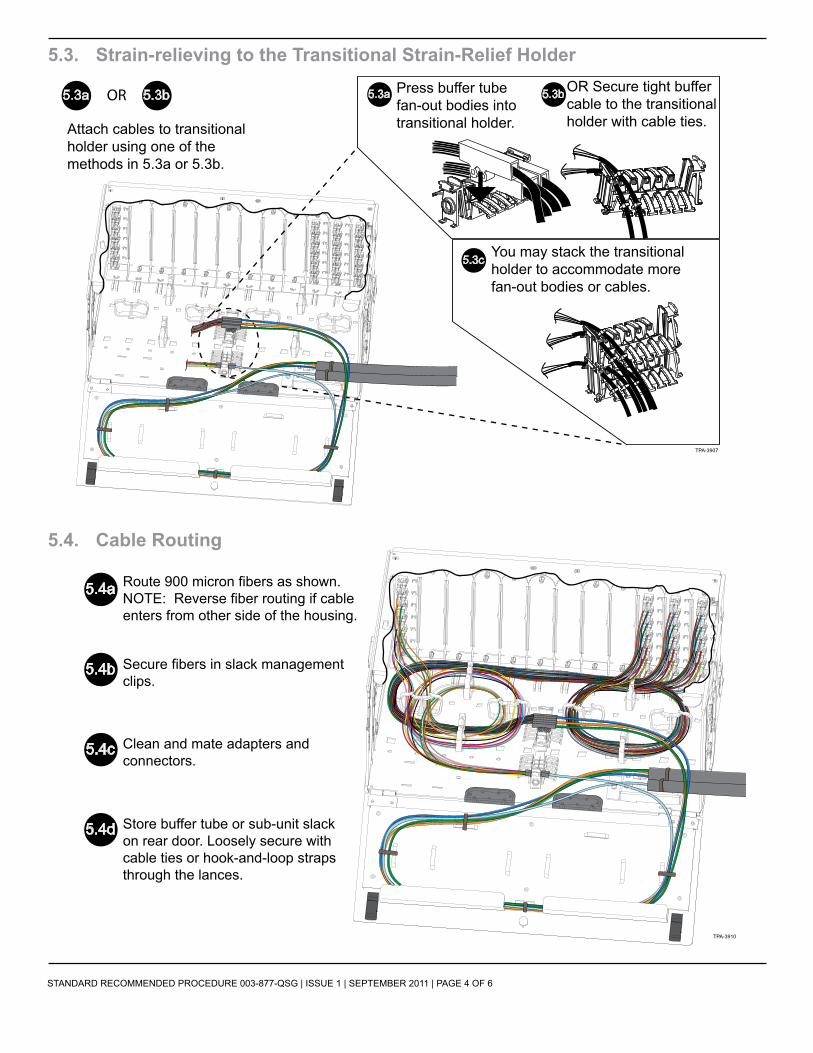
5.3. Strain-relieving to the Transitional Strain-Relief Holder
5.4. Cable Routing
TPA-3907
Attach cables to transitional holder using one of the methods in 5.3a or 5.3b.
OR Secure tight buffer cable to the transitionalholder with cable ties.
5.3c You may stack the transitional holder to accommodate morefan-out bodies or cables.
OR
5.4a Route 900 micron fibers as shown.NOTE: Reverse fiber routing if cable enters from other side of the housing.
5.4b Secure fibers in slack management clips.
5.4c Clean and mate adapters and connectors.
5.4d Store buffer tube or sub-unit slack on rear door. Loosely secure with cable ties or hook-and-loop straps through the lances.
TPA-3910
STANDARD RECOMMENDED PROCEDURE 003-877-QSG | ISSUE 1 | September 2011 | PAGE 5 OF 6
Corning Cable Systems LLC • PO Box 489 • Hickory, NC 28603-0489 USA 1-800-743-2671 • FAX +1-828-325-5060 • International +1-828-901-5000 • http://www.corning.com/cablesystems
Corning Cable Systems reserves the right to improve, enhance, and modify the features and specifications of Corning Cable Systems’ products without prior notification. ClearCurve is a registered trademark of Corning Incorporated. All trademarks are the properties of their respective owners. Corning Cable Systems is ISO 9001 certified.
Record connections on label card using label provided. (Oruse Avery® label 5162 [1 1/3” x 4”].) Store card on front door or in slot in the base of the housing.
TPA-3908
Slide housing into frame. Ensure latch engages on each side inside the housing.
6c
STANDARD RECOMMENDED PROCEDURE 003-877-QSG | ISSUE 1 | September 2011 | PAGE 6 OF 6