15
5-Axis Vertical Machining Centers

5-Axis Vertical Machining Centers

5-Axis Vertical Machining Centers
1 2
5-Axis AutoTuning System
* The merging ofMechanics - Electronics – Information (IT) - Knowledge (Creation)technologies, only Okuma can provide, asYour Single Source for Machine & Control.
Innovations involumetric accuracy
A 5-axis machine thatreally cuts
Material: S45C
The MU-V series—Changing perceptionsof what a 5-axis machine can do
Machining accuracy and capacity similar to 3-axis machines is achieved with a machine design that utilizes “M-E-I-K”*.
The MU-8000V is the latest addition to the MU-V series that combines the above with ease of use and has changed the way people think about 5-axis machines.
Photos used in this brochure include optional equipment.
Thermo-FriendlyConcept
Collision AvoidanceSystem
MachiningNavi Servo Navi
� Highly rigid trunnion table supportshigh accuracy and quality
� High accuracy maintained over longtimes with synergistic effect ofOkuma Intelligent Technology
� Face milling: 504 cm3/min� End milling: 672 cm3/min� Process-intensive machining with
turningTurning: 3 mm2
� Superb operator access to the machining chamber
� Even with long travel and large workpieces, machining with space to spare
� Tools can be changed even with the trunnion table swung out
The value of good vis-ibility and operability required in 5-axis ma-chining

Touch probe
Datum sphere
3 4
Highly rigid trunnion table supportshigh-accuracy 5-axis machining
High accuracy maintained over long times in 5-axis machining
Trunnion table
With just a touch probe and datum sphere—auto tuning completed.
[Examples ofgeometric error]
Next generation of 5-axis machining centers bringinnovations to volumetric accuracy in 5-axis machiningHigh-accuracy machines that go beyond normal expectations of a 5-axis machine
■ Automatic tuning for geometric error is quick,easy, and can be done by anyone
Automatic tuning of a total of 11 different kinds of geometric error, including spindle misalignment and inclination.The accuracy of 5-axis machines is measured in less than 10 minutes to draw out maximum performance.
Gauging and compensation of geometric error
5-Axis Auto Tuning System (Optional)
Accuracy changes due to changes in ambient temperature or spindle heat are minimized. When the 5-Axis Auto Tuning System is also used, a synergistic effect is achieved with the two Intelligent Technologies and high accuracy is maintained in 5-axis machining even when the environmental temperature changes.
Note: The data mentioned in this brochure are “actual data” and do not represent guaranteed accuracies.
Thermo-Friendly ConceptThe unique approach of “accepting temperature changes”
Maximized machining accuracies
YC
Perpendicularity ofC and Y axes
Perpendicularity ofZ and X axes
X
Z
A-axis misalignment inY-axis direction
Y
A
8˚C
0
-100
10
-100
10
-100
10
4 8 12Time [h]
Def
orm
atio
n [µ
m]
Roo
m t
emp
[˚C
]
16 20 24Room temperature: 20˚C
Z axis: 7 µm
Y axis: 5 µm
X axis: 7 µm
MU-5000V thermal deformation over time (Actual data)
(A axis - 45˚ )
202428
● Highly-rigid trunnion table supports both ends● With ball-screw cooling (Std), reduced following error is achieved while
maintaining highly accurate machining.
■ High quality machined surfaces with thehigh following of 5-axis machining
● Indexing accuracy· A-axis indexing accuracy/Indexing return accuracy: ±0.68 sec/±0.40 sec· C-axis indexing accuracy/Indexing return accuracy: ±0.78 sec/±0.14 sec
● Fast operation· A-axis/C-axis 90°clamp/unclamp indexing time: 1.0 sec/1.2 sec
■ The indexing accuracies that take5-axis machining to higher accuracies (MU-5000V Actual data)
■ 5-Axis Auto Tuning System accuracy maintained
5 6
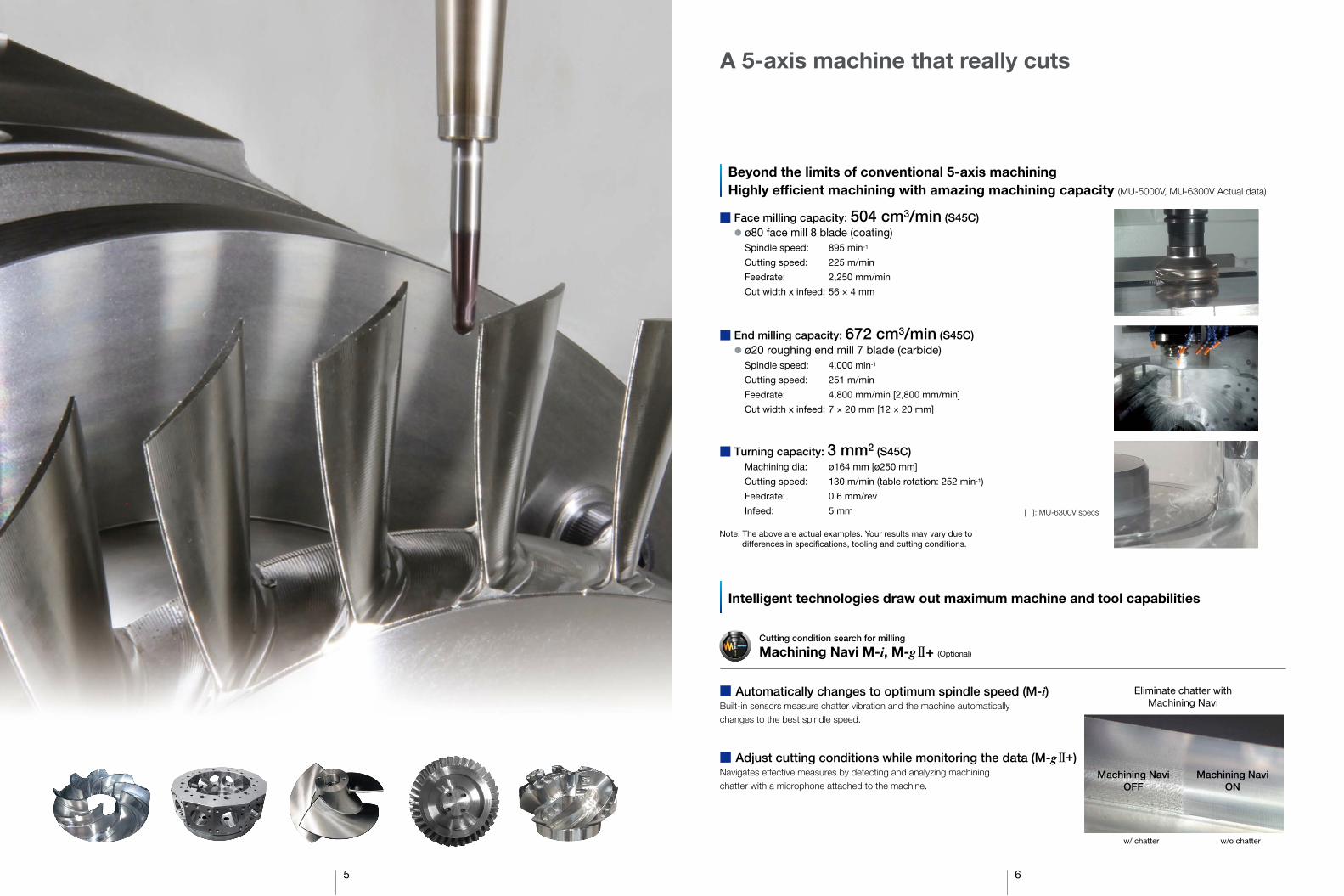
Beyond the limits of conventional 5-axis machiningHighly efficient machining with amazing machining capacity (MU-5000V, MU-6300V Actual data)
Intelligent technologies draw out maximum machine and tool capabilities
A 5-axis machine that really cuts
■ Face milling capacity: 504 cm3/min (S45C) ● ø80 face mill 8 blade (coating)
Spindle speed: 895 min-1
Cutting speed: 225 m/min
Feedrate: 2,250 mm/min
Cut width x infeed: 56 × 4 mm
■ End milling capacity: 672 cm3/min (S45C) ● ø20 roughing end mill 7 blade (carbide)
Spindle speed: 4,000 min-1
Cutting speed: 251 m/min
Feedrate: 4,800 mm/min [2,800 mm/min]
Cut width x infeed: 7 × 20 mm [12 × 20 mm]
■ Turning capacity: 3 mm2 (S45C) Machining dia: ø164 mm [ø250 mm]
Cutting speed: 130 m/min (table rotation: 252 min-1)
Feedrate: 0.6 mm/rev
Infeed: 5 mm
Note: The above are actual examples. Your results may vary due todifferences in specifications, tooling and cutting conditions.
Machining NaviON
Eliminate chatter withMachining Navi
Machining NaviOFF
w/ chatter w/o chatter
[ ]: MU-6300V specs
■ Automatically changes to optimum spindle speed (M-i)Built-in sensors measure chatter vibration and the machine automaticallychanges to the best spindle speed.
■ Adjust cutting conditions while monitoring the data (M-gII+)Navigates effective measures by detecting and analyzing machiningchatter with a microphone attached to the machine.
Machining Navi M-i, M-gII+ (Optional)
Cutting condition search for milling
5 6
Beyond the limits of conventional 5-axis machiningHighly efficient machining with amazing machining capacity (MU-5000V, MU-6300V Actual data)
Intelligent technologies draw out maximum machine and tool capabilities
A 5-axis machine that really cuts
■ Face milling capacity: 504 cm3/min (S45C) ● ø80 face mill 8 blade (coating)
Spindle speed: 895 min-1
Cutting speed: 225 m/min
Feedrate: 2,250 mm/min
Cut width x infeed: 56 × 4 mm
■ End milling capacity: 672 cm3/min (S45C) ● ø20 roughing end mill 7 blade (carbide)
Spindle speed: 4,000 min-1
Cutting speed: 251 m/min
Feedrate: 4,800 mm/min [2,800 mm/min]
Cut width x infeed: 7 × 20 mm [12 × 20 mm]
■ Turning capacity: 3 mm2 (S45C) Machining dia: ø164 mm [ø250 mm]
Cutting speed: 130 m/min (table rotation: 252 min-1)
Feedrate: 0.6 mm/rev
Infeed: 5 mm
Note: The above are actual examples. Your results may vary due todifferences in specifications, tooling and cutting conditions.
Machining NaviON
Eliminate chatter withMachining Navi
Machining NaviOFF
w/ chatter w/o chatter
[ ]: MU-6300V specs
■ Automatically changes to optimum spindle speed (M-i)Built-in sensors measure chatter vibration and the machine automaticallychanges to the best spindle speed.
■ Adjust cutting conditions while monitoring the data (M-gII+)Navigates effective measures by detecting and analyzing machiningchatter with a microphone attached to the machine.
Machining Navi M-i, M-gII+ (Optional)
Cutting condition search for milling
Operatorplatform
7 8
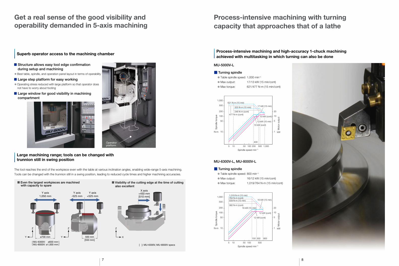
Large machining range; tools can be changed withtrunnion still in swing position
Get a real sense of the good visibility and operability demanded in 5-axis machining
Superb operator access to the machining chamber
ø700 mm
Y axis1,050 mm
500 mm[550 mm]
Y
Z
Y
Z
■ Even the largest workpieces are machinedwith capacity to spare
Y axis+525 mm
The tool reaches the end of the workpiece even with the table at various inclination angles, enabling wide-range 5-axis machining.
Tools can be changed with the trunnion still in a swing position, leading to reduced cycle times and higher machining accuracies.
■ Visibility of the cutting edge at the time of cutting also excellent
X
Z
X axis+450 mm[510 mm]
[ ]: MU-6300V, MU-8000V specs
Y axis-525 mm
Process-intensive machining and high-accuracy 1-chuck machiningachieved with multitasking in which turning can also be done
Process-intensive machining with turningcapacity that approaches that of a lathe
5 10 100 500200
400
10
50
100
200
1
5
10
20
500
1,000
1,00050
621 N-m (15 min)
325 N-m (15 min)
248 N-m (cont)
17 kW (15 min)
477 N-m (cont)13 kW (cont)
10 kW (cont)
13 kW (15 min)
■ Turning spindle● Table spindle speed: 1,000 min-1
● Max output: 17/13 kW (15 min/cont)
● Max torque: 621/477 N-m (15 min/cont)
MU-5000V-L
■ Turning spindle● Table spindle speed: 800 min-1
● Max output: 16/12 kW (15 min/cont)
● Max torque: 1,019/764 N-m (15 min/cont)
MU-6300V-L, MU-8000V-L
5 10 100 500
300 800150
10
50
100
200
1
5
10
20
500
1,000
50
764 N-m (cont)509 N-m (15 min)
382 N-m (cont)
16 kW (15 min)
1,019 N-m (15 min)
12 kW (cont)
12 kW (cont)
16 kW (15 min)
■ Structure allows easy tool edge confirmation during setup and machining
● Best table, spindle, and operation panel layout in terms of operability
■ Large step platform for easy working● Operating stress reduced with large platform so that operator does
not have to worry about footing
■ Large window for good visibility in machiningcompartment
MU-6300V: ø830 mm[MU-8000V: ø1,000 mm]
Spindle speed min-1
Spindle speed min-1
N-m
Spi
ndle
torq
ue
kW
Mot
or o
utpu
t
N-m
Spi
ndle
torq
ue
kW
Mot
or o
utpu
t

9 10
Productivity can be further improved witha wide array of automation options
Flexible automation options Excellent chip discharge
■ ATC magazines● 48 tools, 64 tools: Chain magazine system
● Over 64 tools: Matrix magazine system
■ Auto pallet changer (APC)● External setup of workpiece preparations improve machine utilization
● Good access to machine interior even with APC specs
● Turning specs can also be selected
● Max ports: 8 ports* (Optional)Table center supply
Matrix magazine specificationsfor No. 50, 64-166 tools
Matrix magazine(Photographed without front covers)
8 ports
*Different for turning specifications and APC specifications.
■ Auto tool gauging withworkpiece mounted
Gauge
Matrix magazine
APC setup station MU-6300V 2-pallet APC specs
Safe, reliable chip discharge
■ Recommended Chip Conveyors (Please contact an Okuma sales representative for details.)
: Recommended: Recommended with conditions
Off-machine chip discharge (lift-up chip conveyor)(Optional)
Quick and smooth chip discharge with saddle-mounted washer and in-machine coil chip conveyor
In-machine chip discharge (coil) (Standard)
Washer on saddle (Standard)
Tool breakage detection/Auto tool length compensation
Interface
■ Extra ports for complex hydraulic/pneumatic fixture arrangements
■ Automatically measures workpiece alignment and dimensions
Touch probe
Auto zero offset / Auto gauging(radio transmission)
Probe / CNCtransmission
■ Off-machine lift-up chip conveyors
Type
Shape
Hinge Scraper Scraper (with drum filter) Hinge + scraper (with drum filter)
*1. When there are many fine chips *2. When chips are longer than 100 mm *3. When chips are shorter than 100 mm *4. When there are few fine chips
Workpiece material Steel
Chip shape
In-machine
Off-machine(Optional)
Coil (Standard)
Hinge
Scraper
Scraper (with drum filter)
Hinge + scraper (with drum filter)
FC Mixed (general use)
—
—
*1
(Dry-Wet)
—
(Dry)
(Wet) with magnet
(Wet) *2
—
—
—
*3
*4
—
—
Aluminum / Nonferrous

11 12
High accuracy 5-axis machining is achieved withadvanced technology
■ TAS-C (Thermo Active Stabilizer—Construction) ■ TAS-S (Thermo Active Stabilizer—Spindle)
The TAS-C environmental thermal deformation control accurately controls the machine's structural thermal deformation; by taking into consideration the machine's thermal deformation characteristics, temperature data from properly placed sensors, and feed axis positioning information.
The TAS-S spindle thermal deformation control takes into account various conditional changes such as the spindle's temperature data, modification of the spindle rotation and speed, as well as spindle stoppage. The spindle's thermal deformation will be accurately controlled, even when the rotating speed changes frequently.
■ Eliminate waste with theThermo-Friendly Concept
Machining dimensional change over timeminimized with outstanding dimensional stability
Thermo Active Stabilizer—Construction (TAS-C)Thermo Active Stabilizer—Spindle (TAS-S)
Forced cooling and restrainingof thermal deformation
In addition to maintaining high dimensional accuracy when room temperature changes, Okuma’s Thermo— Friendly Concept provides high dimensional accuracy during machine startup and machining restart.To stabilize thermal deformation, warming-up time is shortened and the burden of dimensional correction during machining restart is reduced.
High dimensional stability
Machining restart
Room temp change
Machine startup
Thermo-Friendly ConceptThe unique approach of “accepting temperature changes”
■ Thermo-friendly structure gives outstanding thermal stability
■ Higher accuracies in 5-axis machining5-axis machining accuracy is greatly affected by misalignment and other “geometric errors” on the rotary axis. The 5-Axis Auto Tuning System measures geometric error using a touch probe and datum sphere, and performs compensation using measurement results to tune the movement accuracy on 5-axis machines. In this way 5-axis machining accuracy on a higher level is achieved.
■ Quick and easy tuning by anyonePreviously, manual measurements of the indexing center were bothersome and time-consuming, but with the 5-Axis Auto Tuning System the measurements are made automatically by the machine. Measurements can therefore be done with stable accuracy in a short time by anyone. (Up to 11 geometric errors tuned automatically.) In addition, the results of tuning are applied regardless of whether the operation in auto, manual, or MDI and whether Tool Center Point Control is on or off. Setup and machining can therefore be done with the same operations as before.
Press START MEASURE key
and cycle start button
5-Axis Auto Tuning System (Optional)
Gauging and compensation of geometric error
Accuracy
Workefficiency
Manual
General autocompensation
With5-Axis Auto Tuning
System
30 min to 1 hour
12 µm 3 µm(Actual values
with MU-6300V)
5 to 10 min
Accuracyimprovement
11 types
4 types
Collision Avoidance System (Optional)
Collision prevention
■ World’s first “Collision-Free Machine”CAS prevents collisions in automatic or manual mode, providing risk-free protection for the machine and great confidence for the operator.
Machining Navi M-i, M-gII+ (Optional)
Cutting condition search for milling
■ Automatically changes to optimum spindle speed (M-i)
■ Adjust cutting conditions while monitoring the data (M-g II+)
■ Vibration waveform display
Automatic ON/OFF control
Machining Navi(OSP) provides
the answer!
This sign indicates achange to the optimumspindle speed.
This sign indicates thatspindle speed is beingchanged.
This sign indicates thatthe cutting load needsto be reduced.
Thermo-FriendlyConcept
Machine coversPeripheral equipment placementMachine "hot spots" diffused
Machine designs thatequalize ambient
temperatures
Symmetrically builtThick walls
Simple machineconstruction
Thermo Active Stabilizer -Construction (TAS-C)Thermo Active Stabilizer -Spindle (TAS-S)
Highly AccurateControl Technology
2. Manageable thermal deformation
3. Accurate compensation
1. Minimal thermal deformation
Timereduction
Based on the chatter noise captured by the microphone, Machining Navi displays a number of optimal spindle speed possibilities on the screen. The operator can change to the indicated spindle speed with a single touch and immediately confirm the result.
Sensors built in to the machine detect and analyze machining chatter. Machining Navi then navigates to the effective measures in a wide range of spindle speeds, from low to high.
Electricity consumption during non-machining time greatly reduced with “ECO Idling Stop”, which shuts down each piece of auxiliary equipment not in use.
■ ECO suite benefits
ECO Idling StopMachine tool idling stop
Intelligent energy-saving function with the Thermo-Friendly Concept.The machine itself determines whether or not cooling is needed and cooler idling is stopped with no loss to accuracy. (Standard application on machines with Thermo-Active Stabilizer—Spindle)
Power is shown individually for spindle, feed axes, and auxiliaries on the OSP operation screen. The energy-saving benefits from auxiliary equipment stopped with ECO Idling Stop can be confirmed on the spot.
Only the necessary units run
● “ECO Idling Stop” for operation of necessary units only
● “ECO Power Monitor” for visual graphics of power
● Intermittent/continuous operation of chip conveyor and mist collector during operation — “ECO Operation” (Optional)
● Energy-saving hydraulic unit using servo control technology —“ECO Hydraulics” (Optional)
ECO Idling StopAccuracy ensured, cooler off
ECO Power MonitorOn-the-spot check of energy savings
■ ECO suite provides a suite of energy-saving functions that can be used on machines
[Optional] [Optional]

13 14
On table travel type machining centers, the table feed accelera-tion with the previous system was the same regardless of weight, such as workpieces and fixtures loaded on the table.
Work Weight Auto Setting estimates the weight of the workpiece and fixture on the table and automatically sets servo parameters, including acceleration, to the optimum values. Cycle times are shortened with no changes to machining accuracy.
SERVONAVI AI (Automatic Identification)
Achieves long term accuracy and surface quality
■ Cycle time shortened with faster acceleration
Work Weight Auto Setting
Slide resistance changes with length of time machine tools are utilized, and discrepancies occur with the servo parameters that were the best when the machine was first installed. This may produce crease marks at motion reversals and affect machining accuracy (part surface quality). SERVONAVI’s Reversal Spike Auto Adjustment maintains machining accuracy by switching servo parameters to the optimum values matched to changes in slide resistance.
SERVONAVI SF (Surface Fine-tuning)
■ Maintains machining accuracy and surface quality
Reversal Spike Auto Adjustment
Comparison of DBB measurements
Optimized Servo Control
Dynamic Tool Load Control (Optional)
SERVONAVI
Prevents chipping, extends tool life
When machining of difficult-to-cut material, chipping from blade runout often occurs with insert-type end mills. To stabilize such machining, solid end mills with high tool costs have generally been used.Dynamic Tool Load Control gives uniform cutting force with
advanced synchronization of spindle phase and feed rate to control insert-type end mill chipping. This improves tool life and stabilizes machining. Switching from expensive solid tools also leads to reduced tool costs.
Insert tipped end mill
Runout of insert-type endmill tool edge
DTLC “Off”
DTLC “On”
(Chip volume) 0 2,000 4,000 6,000 8,000 10,000 (cm3)
[Actual results] Chip volume per tool under the same cutting conditions (tool life)
Tool life when cutting titanium
About 2.3-times longer(Okuma comparison)
With simultaneous 5-axis control that producesexcellent machined surface quality
Simultaneous 5-axis kit makes it even easierBecause “Machine & Control” OSP provides advanced features
High speed NC function for high accuracy, high quality, and high speed marchining of curved surfaces of any shape with newly-developed “sculptured-surface adaptive acceleration control.”
■ High Speed ContouringSuper-NURBS (5-axis specs)(Optional)
■ Super-NURBS
Shaping feedratesmuch faster
Shaping feedrates much faster Much faster acceleration
Position
■ Before
Position
This feature will provide rotary operation with a tool point as the center when operating the rotary axes manually. When the table is swiveled, axis movement will occur with no change in the tool position on the workpiece.
■ Tool center point controlmanual feed (Optional)
A feature to perform X-Y-Z-axis manual feed (rapid traverse, cutting feed, pulse handle) when origin coordinate systems shift on a swiveling table.
■ Table origin coordinatemanual feed (Optional)
Function controls the path of the tool tip with respect to the workpiece on each axis so that the tool tip trajectory is linear with the axis travel command including the A, B, and C axes.● In the case of simultaneous Y-axis and
A-axis commands witih the linear command (G01), the tool path is a straight line when viewed from the workpiece.
WithTTC
No change in tool tilt Gradual change in tool tilt
C-axis rotation center
Work coordinateorigin
Table referencecoordinate
Y
Y
X
X
X axis
Y axis
+
+
−
− CommandY axis
Z
Y
The tool angle on a workpiece (tool tilt) in 5-axis machining will change on a waving surface. CAM processing errors will cause the tool to stagger with unnecessary accel/decel and reverse angles during axis feed. Simul 5-Axis TTC will keep feedrates steady with a smooth sequence of commands to automatically correct tool tilt angles—resulting in shorter cycle times and smoother surface finishes.
■ Tool tilt compensation
When aging changes machine performance, noise, vibration, crease marks, or fish scales may appear.
Vibration Auto Adjustment can quickly eliminate noise and vibration even from machines with years of operation.
■ Contributes to longer machine life
Vibration Auto Adjustment
Insert
End mill
Runout: large
Difference in runout
Runout: small
Without control
Runout: small
Cutting force: small
Runout: large
Cutting force: large
With controlRunout: large
Controls feed amount for All blade runouts
Gives uniform cutting force
Note: The above are actual examples. Your results may vary due to differences in specifications, tooling and cutting conditions.
Before adjustment After adjustment
■ Tool center point control (Optional)
A axis
Staggered tool angles
Feed
rate
Feed
rateAcceleration
SERVONAVI
Previous controlLow
High
Heavy Light
Workpieceweight
Higheracceleration,shorter cycletime
(Included in Tool Center Point Control �)

15 16
■ Machine specifications
X axis
Y axis
Z axis
A axis
C axis
Table surface to spindle nose
Table size
Max work size
Floor to table top
Max load capacity*
(turning spindle speed)
Spindle speed
Tapered bore
No. of spindle ranges
Bearing dia
Rapid traverse
Rapid traverse
Cutting feedrate
Spindle (10 min/cont)
Feed axes
Tool shank
Pull stud
Tool capacity (magazine)
Max tool dia (w/adjacent / w/o adjacent)
Max tool length
Max tool weight
Tool selection
Height
Floor space W x D (w/o operator platform)
Weight
Travels
Table
Spindle
Feed
Motors
ATC
Machinesize
CNC
Item Unit
925 (36.42)
1,050 (41.34) (+100 ATC movements)
600 (23.62)
+90 to -120
360
160 to 760 (6.30 to 29.92)
ø630 (24.80)
ø830 × H550 (ø32.68 × H21.65)
1,150 (45.28)
600 (1,320)
<800>
Infinitely variable
X-Y-Z: 50 (1.97)
A: 10,800 (30 min-1) C: 32,400 (90 min-1)
X-Y-Z: 1 to 50,000
X: 5.2 (6.9), Y-Z: 3.5 (4.7), A: 4.6 × 2 (6.1 × 2), C: 7.2 (9.6) <16.0 (21.3)>
MAS2 <—>
32-tool [48-tool, 64-tool: chain, Over¥64-tool: matrix]
400 (15.75)
Memory random (matrix magazine is fixed address system)
3,525 (138.78)
4,850 × 2,990 (190.94 × 117.72)
OSP-P300M <OSP-P300S>
10,000 [15,000, 20,000, 25,000]<8,000, [12,000]>
7/24 taper No.40 <HSK-A63>
ø70 (2.76)
11/7.5 (15/10) [22/18.5 (30/25),30/22 (40/30), 15/11 (20/15)]
<11/7.5 (15/10), [22/18.5 (30/25)]>
MAS BT.40 <HSK-A63>
ø90/ø125 (ø3.54/ø4.92)
8 (17.6)
3,995 × 2,750 (157.28 × 108.27)
15,400 (33,880)
6,000 [12,000]<10,000>
7/24 taper No.50 <HSK-A100>
ø90 (3.54)
11/7.5 (15/10) [26/18.5 (35/25)]<26/18.5 (35/25)>
MAS BT.50 <HSK-A100>
ø100/ø152 (ø3.94/5.98)
12 (26.4) [15 (33)]
3,995 × 2,840 (157.28 × 111.81)
15,650 (34,430)
10,000 [15,000, 20,000, 25,000]<8,000, [12,000]>
7/24 taper No.40 <HSK-A63>
ø70 (2.76)
11/7.5 (15/10) [22/18.5 (30/25),30/22 (40/30), 15/11 (20/15)]
<11/7.5 (15/10), [22/18.5 (30/25)]>
MAS BT.40 <HSK-A63>
ø90/ø125 (ø3.54/ø4.92)
8 (17.6)
17,500 (38,500)
6,000 [12,000]<10,000>
7/24 taper No.50 <HSK-A100>
ø90 (3.54)
11/7.5 (15/10) [26/18.5 (35/25)]<26/18.5 (35/25)>
MAS BT.50 <HSK-A100>
ø100/ø152 (ø3.94/5.98)
12 (26.4) [15 (33)]
17,700 (38,940)
10,000 [15,000, 20,000, 25,000]<8,000, [12,000]>
7/24 taper No.40 <HSK-A63>
ø70 (2.76)
11/7.5 (15/10) [22/18.5 (30/25),30/22 (40/30), 15/11 (20/15)]
<11/7.5 (15/10), [22/18.5 (30/25)]>
MAS BT.40 <HSK-A63>
ø90/ø125 (ø3.54/ø4.92)
8 (17.6)
.
18,400 (40,480)
800 (31.50)
1,050 (41.34)
600 (23.62)
+90 to -120
360
80 to 680 (3.15 to 26.77)
ø500 (19.69)
ø700 × H500 (ø27.56 × H19.69)
1,140 (44.88)
500 (1,100)
<1,000>
Infinitely variable
X-Y-Z: 50 (1.97)
A: 18,000 (50 min-1) C: 18,000 (50 min-1) <36,000 (100 min-1)>
X-Y-Z: 1 to 50,000
X: 5.2 (6.9), Y-Z: 3.5 (4.7), A: 3.5 × 2 (4.7 × 2), C: 3.0 (4) <5.0 (6.7)>
MAS2 <—>
32-tool [48-tool, 64-tool: chain, Over¥64-tool: matrix]
400 (15.75)
Memory random (matrix magazine is fixed address system)
3,435 (135.24)
OSP-P300M <OSP-P300S>
925 (36.42)
1,050 (41.34) (+100 ATC movements)
600 (23.62)
+90 to -120
360
200 to 800 (7.87 to 31.50)
ø800 (31.50) × 630 (24.80) width <ø800 (31.50)>
ø1,000 × H550 (ø39.37 × H21.65)
1,210 (47.64)
700 (1,540)
<800>
Infinitely variable
X-Y-Z: 50 (1.97)
A: 10,800 (30 min-1) C: 32,400 (90 min-1)
X-Y-Z: 1 to 50,000
X: 5.2 (6.9), Y-Z: 3.5 (4.7), A: 4.6 × 2 (6.1 × 2), C: 7.2 (9.6)
MAS2 <—>
32-tool [48-tool, 64-tool: chain, Over¥64-tool: matrix]
400 (15.75)
Memory random (matrix magazine is fixed address system)
3,625 (142.72)
5,280 × 2,990 (207.87 × 117.72)
OSP-P300M <OSP-P300S>
[ ]: Optional
< >: Turning specifications
6,000 [12,000]<10,000>
7/24 taper No.50 <HSK-A100>
ø90 (3.54)
11/7.5 (15/10) [26/18.5 (35/25)]<26/18.5 (35/25)>
MAS BT.50 <HSK-A100>
ø100/ø152 (ø3.94/5.98)
12 (26.4) [15 (33)]
18,600 (40,920)
mm (in.)
mm (in.)
mm (in.)
deg
deg
mm (in.)
mm (in.)
mm (in.)
mm (in.)
kg (lb)
min-1
min-1
mm (in.)
m/min (ipm)
deg/min
mm/min
kW (hp)
kW (hp)
mm (in.)
mm (in.)
kg (lb)
mm (in.)
mm (in.)
kg (lb)
MU-5000V <-L> No. 40 spindle MU-5000V <-L> No. 50 spindle MU-6300V <-L> No. 40 spindle MU-6300V <-L> No. 50 spindle MU-8000V <-L> No. 40 spindle MU-8000V <-L> No. 50 spindle
* With APC specifications, there are limits on maximum pallet load and maximum workpiece dimensions

17 18
50 100 1,000 5,000
10
50
100
200
Spindle speed min-1
10,000500 50 100 1,000 5,000500
1
5
10
20
530 1,200
11 kW (10 min)
11 kW (5 min)198 N-m (5 min)
135 N-m (cont)
7.5 kW (cont)
10
50
100
200
1
5
10
20
10,000
6,0001,200530
11 kW (10 min)
7.5 kW (cont)
198 N-m (5 min)
135 N-m (cont)
11 kW (5 min)
50 100 1,000 5,000
10
50
100
200
10,000500 50 100 1,000 5,000 10,000500
4,000
2,500
1
5
10
20
720
199 N-m (5 min)
146 N-m (cont)
15 kW (5 min) 22 kW (10 min)
10
50
100
200
1
5
10
20
57 N-m (10 min)
42 N-m (cont)
30 kW (10 min)
15,000 20,000
50 100 1,000 5,000
10
50
100
200
10,00050050 100 1,000 5,000 20,000
10
50
100
200
10,000500
1
5
10
20
25,000 2,500
1
5
10
20
720 12,0004,000
26 kW (10 min)
3,600
29 N-m (10 min)
20 N-m (cont)
11 kW (10 min)
15 kW (10 min)
18.5 kW (cont)
11 kW (cont)
199 N-m (5 min)
146 N-m (cont)
15 kW (5 min)
■ Standard spindle No. 40● Speed 10,000 min-1 (8,000 min-1 with turning specifications)
● Max output 11/7.5 kW (10 min/cont)● Max torque 198/135 N-m (5 min/cont)
■ Standard spindle No. 50● Speed 6,000 min-1
● Max output 11/7.5 kW (10 min/cont)● Max torque 198/135 N-m (5 min/cont)
kWN-m
Sp
ind
le t
orq
ue
Mot
or o
utp
ut
Spindle speed min-1
kWN-m
Sp
ind
le t
orq
ue
Mot
or o
utp
ut
Spindle speed min-1
kWN-m
Sp
ind
le t
orq
ue
Mot
or o
utp
ut
Spindle speed min-1
kWN-m
Sp
ind
le t
orq
ue
Mot
or o
utp
ut
Spindle speed min-1
kWN-m
Sp
ind
le t
orq
ue
Mot
or o
utp
ut
Spindle speed min-1
kWN-m
Sp
ind
le t
orq
ue
Mot
or o
utp
ut
Wide-range sp 50 to 15,000 min-1
High-speed sp 50 to 20,000 min-1
High-speed sp 50 to 25,000 min-1
Multitasking sp 50 to 8,000 min-1
Multitasking sp 50 to 12,000 min-1
Wide-range sp 50 to 12,000 min-1
Multitasking axis 50 to 10,000 min-1
Dual contact spindle
AbsoScale
Auto pallet changers*7
ATC magazines
Pull stud specs
Table surface*8
Thru-spindle coolant*1
Chip air blower (adapter)
Oil mist coolant
Shower coolant
No. 40 22/18.5 kW (30/25 hp) (10 min/cont) *2
No. 40 30/22 kW (40/30 hp) (10 min/cont) *3
No. 40 15/11 kW (20/15 hp) (10 min/cont) *3
No. 40 11/ 7.5 kW (15/10 hp) (10 min/cont) *4
No. 40 22/18.5 kW (30/25 hp) (10 min/cont) *4
No. 50 26/18.5 kW (35/25 hp) (10 min/cont) *5
No. 50 26/18.5 kW (35/25 hp) (10 min/cont) *6
HSK, BIG-PLUS®, Super BT
X-Y-Z axes
2P-APC, 6P-APC, FMS
48-tool, 64-tool (chain type)64-tool or more (Matrix type)
MAS 1, JIS, CAT, DIN
Tapped table topMU-8000V: ø800 round table
Specify 1.5 MPa or 7.0 MPa. 25,000 min-1
specs available for HSK-A63 only.
Unavailable with thru-spindle specifications
Ceiling mounted, 5 nozzles
Workpiece wash gun
Off-machine chip discharge
Chip bucket for above
Super-NURBS
Tool breakage detection/Auto toollength compensation
Auto zero offset/auto gauging
5-Axis Auto Tuning System
Collision Avoidance System
Machining Navi M-i, M-g +
Tool life management (time counter, etc)
Overload monitor(w/ feed adaptive control)
Automatic door
Chemical anchors
TAS-S
TAS-C
Lift-up chip conveyors: floor type,drum filter type
Touch sensor (Renishaw)Laser sensor (Blum)
Touch probe (Renishaw)
Gauging, compensation for geometric error
Collision prevention
Cutting condition search function formilling/machining
Thermo Active Stabilizer—Spindle
Thermo Active Stabilizer—Construction
: Corresponding standard specification deleted.*1. Okuma pull stud required (End-face grinding, O-ring, and through-hole diameter
differ from those of commercial pull studs.)*2. Spindle accepts 7/24 No. 40 (BT40, BIG-PLUS®, Super BT, CAT40, DIN40), or
HSK-A63 tapers.*3. Spindle accepts 7/24 No. 40 (BIG-PLUS®, Super BT), or HSK-A63 tapers.*4. Tapered bore on turning spindle is HSK-A63. *5. For spindle tapered bore, 7/24 taper No. 50 (BT50, BIG-PLUS®, Super BT, CAT50,
DIN50) is available. *6. Tapered bore on turning spindle is HSK-A100, CAPTO-C6.*7. Limitations to maximum workpiece dimensions, etc.*8. With turning specifications, tapped holes only (no T grooves).
■ Wide-range spindle No. 50 (Optional)
● Speed 12,000 min-1 (10,000 min-1 with turning specifications)● Max output 26/18.5 kW (10 min/cont)● Max torque 199/146 N-m (5 min/cont)
■ High-speed spindle No. 40 (Optional)
● Speed 25,000 min-1
● Max output 15/11 kW (10 min/cont)● Max torque 29/20 N-m (10 min/cont)
■ Wide-range spindle No. 40 (Optional)
● Speed 15,000 min-1 (12,000 min-1 with turning specifications)● Max output 22/18.5 kW (10 min/cont)● Max torque 199/146 N-m (5 min/cont)
■ High-speed spindle No. 40 (Optional)
● Speed 20,000 min-1
● Max output 30/22 kW (10 min/cont)● Max torque 57/42 N-m (10 min/cont)
■ Standard specifications / accessoriesNo. 40 Spindle speed 50 to 10,000 min-1
No. 50 Spindle speed 50 to 6,000 min-1
Rapid feedrate
Spindle·Spindlehead cooling system
Ball screw cooling
Air cleaner (filter)
Operation panel with color LCD
Pulse handle
Tapered bore cleaning bar
A/C axis rotary table
C axis table
Hand tools
Tool release lever
Washing device on saddle
Coolant supply system*1
11/7.5 kW (15/10 hp) [10 min/cont]
11/7.5 kW (15/10 hp) [10 min/cont]
X-Y-Z: 50 m/min
Oil controller
X-Y-Z-axis
Including regulator
0.0001 deg, Including encoder
ø500, 6 18H7 T-slots
ø630, 6 18H7 T-slots
ø800 × 630 width, 5 18H7 T-slots
Tank: 440 L [Effective: 289 L]Pump: 390 W (50 Hz), 620 W (60 Hz)
Tank: 770 L [Effective: 350 L]Pump: 390 W (50 Hz), 620 W (60 Hz)
ATC air blower
Chip air blower
Operator platform
Work lamp
In-machine chip discharge
Chip pan
Foundation washer (with jack bolts)
3-lamp status indicator
32-tool ATC
ATC magazine shutter
Full enclosure shielding
Nozzle type
LED (installed on right and left sides)
Coil type
MU-5000V:Effective capacity 77 LMU-6300V, MU-8000V:Effective capacity 92 L
MU-5000V: 11 pcsMU-6300V, MU-8000V: 12 pcs
Type C (LED signal tower)Red (alarm), Yellow (end)Green (running)
With ceiling (full enclosure)
Note: Oil-based coolants are highly flammable, so fire prevention measures mustalways be taken when using these coolants. Do not operate unattended.
*1. 800-W pump required with oil-based coolant.
MU-5000V
MU-6300V
MU-8000V
MU-5000V
MU-6300VMU-8000V
■ Optional specifications / accessories
■ Multi-pallet APC dimensional drawing
● 2-pallet APC ● 6-pallet APC
134
(5.2
8)
2,436(95.91)
522 (20.55)
386 (15.20)743
(29.25)
(53.
74)
1,36
5
(37.
40)
2,26
7 (8
9.25
)
1,035(40.75)
1,265(49.80)
522(20.55)
743(29.25)
3,645(143.50)
Workpiecestand
Workpiecestand
Spindlecenter
Spindlecenter
Setup station
Setup station
ATC shutter
ATC shutter
APC shutter
APC shutter
(53.
74)
(37.
40)
(29.
53)
4,12
4 (1
62.3
6)
ATC tool change arm
ATC tool change arm
Unit: mm (in.)(with MU-6300V) (Optional)
950
NC cabinet
NC cabinet
1,36
595
075
0
6
45°45°
45°
10°
1
2
2
1
3
4 5
794
(max
wor
kpie
ce w
idth
)
794
(max
wor
kpie
ce w
idth
)
752
(29.
61)
18.5 kW (cont)
11 kW (cont)
22 kW (cont)
11 kW (cont)
7.5 kW (cont)
19
External I/O communicationAdditional RS-232-C channel (Std specs include 1 channel)DNC-T3DNC-B (232C-Ethernet transducer used on OSP side)DNC-DTDNC-C/EthernetAdditional USB (Additional 2 ports, Std: 2 ports)
Automation / untended operationAuto power shut-off
Warm-up (calendar timer) External programselectCycle time reduction (Ignores certain commands)Pallet pool control (PPC) (Required for multi-pallet APC) Robot, loader I/F
High-speed, high-precisionAbsoScale detection5-Axis Auto Tuning SystemStraightness compensation0.1 µm control (linear axis commands)Super-NURBSSimultaneous5-axis kit
TAS-S (Thermo Active Stabilizer—Spindle)TAS-C (Thermo Active Stabilizer—Construction)
ECO suite (energy saving functions)ECO OperationECO Power MonitorEnergy-savinghydraulic unit
OtherControl cabinet lamp (inside)Circuit breakerSequence operationUpgraded sequence restartTool point center manual feedTable reference coord manual feedPulse handleExternal M signalsCollision Avoidance System (CAS)Machining Navi M-i, M-gII+(cutting condition search)One-Touch SpreadsheetBlock skip; 3 setsLeading edge offsetOSP-VPS (Virus Protection System)19-inch variable angle operating panel
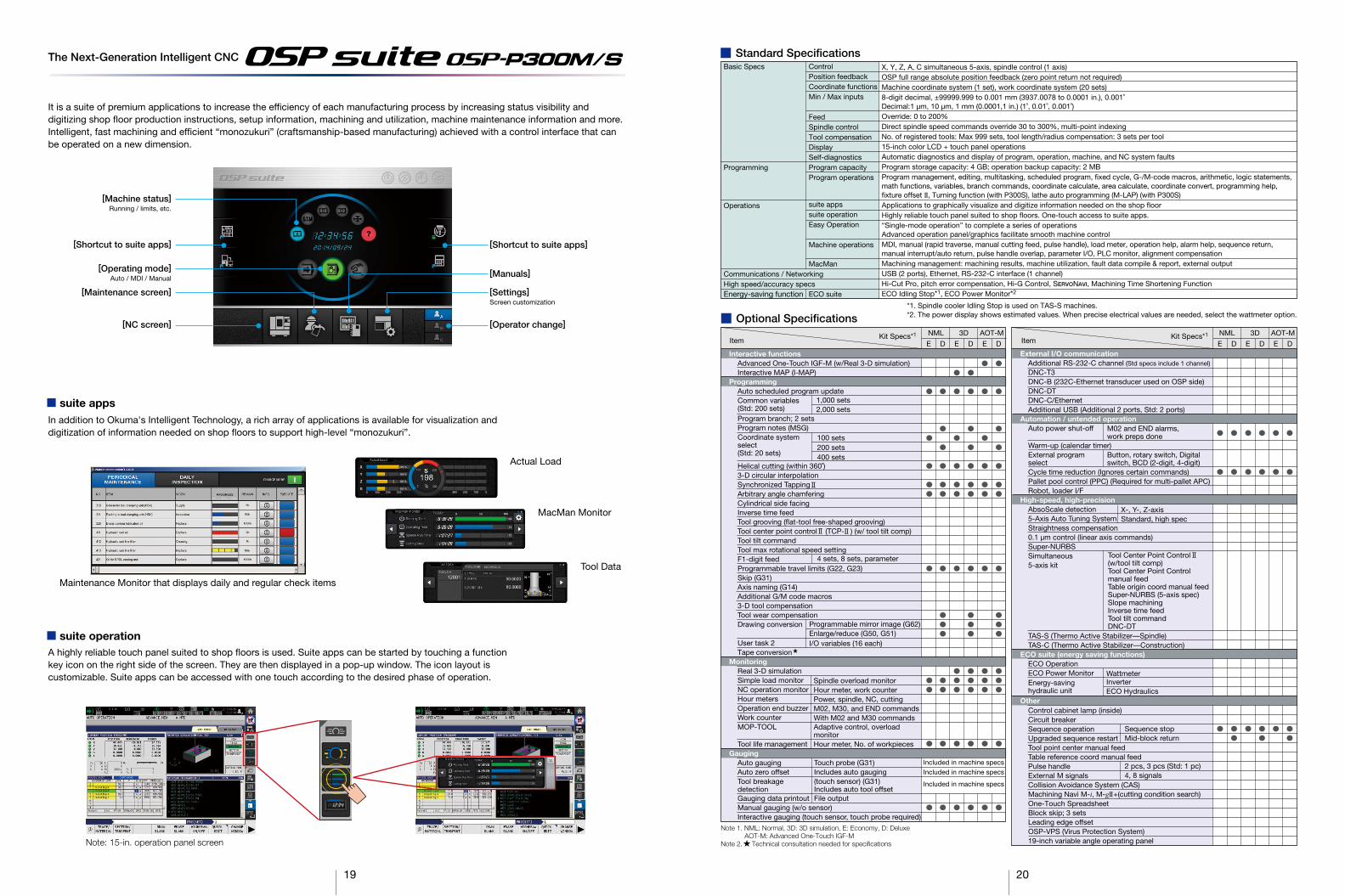
■ Optional Specifications
Interactive functionsAdvanced One-Touch IGF-M (w/Real 3-D simulation)Interactive MAP (I-MAP)
ProgrammingAuto scheduled program updateCommon variables(Std: 200 sets)Program branch; 2 setsProgram notes (MSG)Coordinate systemselect(Std: 20 sets)
Helical cutting (within 360˚)3-D circular interpolationSynchronized TappingArbitrary angle chamferingCylindrical side facingInverse time feedTool grooving (flat-tool free-shaped grooving)Tool center point control (TCP- ) (w/ tool tilt comp)Tool tilt commandTool max rotational speed settingF1-digit feedProgrammable travel limits (G22, G23)Skip (G31)Axis naming (G14)Additional G/M code macros3-D tool compensationTool wear compensationDrawing conversion
User task 2Tape conversion
MonitoringReal 3-D simulationSimple load monitorNC operation monitorHour metersOperation end buzzerWork counterMOP-TOOL
Tool life managementGauging
Auto gaugingAuto zero offsetTool breakagedetectionGauging data printoutManual gauging (w/o sensor)Interactive gauging (touch sensor, touch probe required)
ControlPosition feedbackCoordinate functionsMin / Max inputs
FeedSpindle controlTool compensationDisplaySelf-diagnosticsProgram capacityProgram operations
suite appssuite operationEasy Operation
Machine operations
MacMan
ECO suite
■ Standard SpecificationsBasic Specs
Programming
Operations
Communications / NetworkingHigh speed/accuracy specsEnergy-saving function
Item Kit Specs*1
Included in machine specsIncluded in machine specs
Included in machine specs
Item Kit Specs*1NML AOT-M
E D E D E D
NML 3D AOT-M
E D E D E D
3D
■ suite apps
Actual Load
MacMan Monitor
Tool Data
Maintenance Monitor that displays daily and regular check items
The Next-Generation Intelligent CNC
■ suite operation
It is a suite of premium applications to increase the efficiency of each manufacturing process by increasing status visibility anddigitizing shop floor production instructions, setup information, machining and utilization, machine maintenance information and more.Intelligent, fast machining and efficient “monozukuri” (craftsmanship-based manufacturing) achieved with a control interface that can be operated on a new dimension.
X, Y, Z, A, C simultaneous 5-axis, spindle control (1 axis)OSP full range absolute position feedback (zero point return not required)Machine coordinate system (1 set), work coordinate system (20 sets)8-digit decimal, ±99999.999 to 0.001 mm (3937.0078 to 0.0001 in.), 0.001˚Decimal:1 µm, 10 µm, 1 mm (0.0001,1 in.) (1˚, 0.01˚, 0.001˚)Override: 0 to 200%Direct spindle speed commands override 30 to 300%, multi-point indexingNo. of registered tools: Max 999 sets, tool length/radius compensation: 3 sets per tool15-inch color LCD + touch panel operationsAutomatic diagnostics and display of program, operation, machine, and NC system faultsProgram storage capacity: 4 GB; operation backup capacity: 2 MBProgram management, editing, multitasking, scheduled program, fixed cycle, G-/M-code macros, arithmetic, logic statements, math functions, variables, branch commands, coordinate calculate, area calculate, coordinate convert, programming help, fixture offset II, Turning function (with P300S), lathe auto programming (M-LAP) (with P300S)Applications to graphically visualize and digitize information needed on the shop floorHighly reliable touch panel suited to shop floors. One-touch access to suite apps. “Single-mode operation” to complete a series of operationsAdvanced operation panel/graphics facilitate smooth machine controlMDI, manual (rapid traverse, manual cutting feed, pulse handle), load meter, operation help, alarm help, sequence return,manual interrupt/auto return, pulse handle overlap, parameter I/O, PLC monitor, alignment compensationMachining management: machining results, machine utilization, fault data compile & report, external outputUSB (2 ports), Ethernet, RS-232-C interface (1 channel)Hi-Cut Pro, pitch error compensation, Hi-G Control, SERVONAVI, Machining Time Shortening FunctionECO Idling Stop*1, ECO Power Monitor*2
*1. Spindle cooler Idling Stop is used on TAS-S machines.*2. The power display shows estimated values. When precise electrical values are needed, select the wattmeter option.
1,000 sets2,000 sets
100 sets200 sets400 sets
4 sets, 8 sets, parameter
Programmable mirror image (G62)Enlarge/reduce (G50, G51)I/O variables (16 each)
Spindle overload monitorHour meter, work counterPower, spindle, NC, cuttingM02, M30, and END commandsWith M02 and M30 commandsAdaptive control, overloadmonitorHour meter, No. of workpieces
Touch probe (G31)Includes auto gauging(touch sensor) (G31)Includes auto tool offsetFile output
M02 and END alarms,work preps done
X-, Y-, Z-axisStandard, high spec
Wattmeter
Sequence stopMid-block return
2 pcs, 3 pcs (Std: 1 pc)4, 8 signals
InverterECO Hydraulics
Tool Center Point Control(w/tool tilt comp)Tool Center Point Controlmanual feedTable origin coord manual feedSuper-NURBS (5-axis spec)Slope machiningInverse time feedTool tilt commandDNC-DT
Button, rotary switch, Digital switch, BCD (2-digit, 4-digit)
Note 1. NML: Normal, 3D: 3D simulation, E: Economy, D: DeluxeAOT-M: Advanced One-Touch IGF-M
Note 2. Technical consultation needed for specifications
20
[Shortcut to suite apps]
[Operating mode] Auto / MDI / Manual
[Maintenance screen]
[Machine status]Running / limits, etc.
[NC screen]
[Settings]Screen customization
[Operator change]
[Manuals]
[Shortcut to suite apps]
In addition to Okuma's Intelligent Technology, a rich array of applications is available for visualization and digitization of information needed on shop floors to support high-level “monozukuri”.
A highly reliable touch panel suited to shop floors is used. Suite apps can be started by touching a function key icon on the right side of the screen. They are then displayed in a pop-up window. The icon layout is customizable. Suite apps can be accessed with one touch according to the desired phase of operation.
Note: 15-in. operation panel screen

* In the case of APC specification it is different.
21 22
Unit: mm■ Working range
MU-5000V Max table load capacity: 500 kg
MU-6300V Max table load capacity: 600 kg
MU-8000V Max table load capacity: 700 kg
(Maximum tool diameter No. 40) ø125(Maximum tool diameter No. 50) ø152
Automatic tool changer (ATC)
(encircled dimension)Slope entrance prohibited
600
[Z-a
xis
trav
el]
1,050 [Y-axis travel]
+90°
210°
R464
6020
180
80
ø700 workpiece dia
ø500 table dia Table top
525525525(ATC position)
425
440
400
Max
too
l len
gth
C-axis table centerline
A-axis swinginterference range
A-axis center of rotation
A-axis trunnionswing angle
-120°
160
100800 [X-axis travel]
Table center when A axis is 90°Trunnion
ø500
ø700 workpiece dia350450
60
A-axis centerof rotation
500
Wor
kpie
ce h
eigh
t18
0
925 [X-axis travel]
Table center when A axis is 90°Trunnion
ø830 workpiece dia
415510
550
Wor
kpie
ce h
eigh
t21
0
100
A-axis centerof rotation
ø630
(Maximum tool diameter No. 40) ø125(Maximum tool diameter No. 50) ø152
Automatic tool changer (ATC)
600
[Z-a
xis
trav
el]
1,050 [Y-axis travel]
+90°
210°
R500
100
60
210
160
ø830 workpiece dia
ø630 table dia
1,150
525525
100
440
400
Max
too
l len
gth
A-axis center of rotation
A-axis trunnionswing angle
-120°
Automatic tool changer (ATC)
600
[Z-a
xis
trav
el]
1,050 [Y-axis travel]
+90°
ø1,000 workpiece dia
ø800 table dia
1,150
100
525 525
R540
440
250
200
8012
0
400
Max
too
l len
gth
A-axis center of rotation
A-axis trunnionswing angle
(Maximum tool diameter No. 40) ø125
(Maximum tool diameter No. 50) ø152
210°
-120°
550
Wor
kpie
ce h
eigh
t
925 [X-axis travel]
ø1,000 workpiece dia
ø800
510 415
250
Table center when A axis is 90°Trunnion
80
A-axis centerof rotation
Table top
C-axis table centerline
A-axis swinginterference range
Table top
C-axis table centerline
A-axis swinginterference range
550
Wor
kpie
ce h
eigh
t50
0W
orkp
iece
hei
ght
550
Wor
kpie
ce h
eigh
t
Unit: mm■ Max workpiece dimensions (with APC)
MU-5000V (P) Max pallet load capacity: 400 kg
MU-6300V (P)
MU-8000V (P)
600
[Z-a
xis
trav
el]
1,050 [Y-axis travel]
+90°
R464
254
136
180
50 20
ø700 workpiece dia
ø500 table dia
Table top
525 525
C-axis table centerline
A-axis swinginterference range
A-axis center of rotation
A-axis trunnion swing angle
-120°
800 [X-axis travel]
Table center when A axis is 90°Trunnion
ø700
500Workpiece width
350450
A-axis centerof rotation
390
Wor
kpie
ce h
eigh
t 490
390
Wor
kpie
ce h
eigh
t
ø294
Max pallet load capacity: 450 kg
600
[Z-a
xis
trav
el]
1,050 [Y-axis travel]
+90°
R500
278
172
210
60
ø830 workpiece dia
ø630 table dia
Table top
525 525
C-axis table centerline
A-axis swinginterference range
A-axis center of rotation
A-axis trunnion swing angle
-120°
925 [X-axis travel]
Table center when A axis is 90°Trunnion
ø830
794 workpiece width415510
A-axis centerof rotation
450
Wor
kpie
ce h
eigh
t
241
450
Wor
kpie
ce h
eigh
t
ø435
794 workpiece width
Max pallet load capacity: 550 kg
600
[Z-a
xis
trav
el]
1,050 [Y-axis travel]
+90°
R540
2025
0
100
ø1,000 workpiece dia
ø800 table dia
Table top
525 525
C-axis table centerline
A-axis swinginterference range
A-axis center of rotation
A-axis trunnion swing angle
-120°
925 [X-axis travel]
Table center when A axis is 90°Trunnion
ø1,0
00
794 workpiece width415510
A-axis centerof rotation
450
Wor
kpie
ce h
eigh
t
607
450
Wor
kpie
ce h
eigh
t
ø531
794 workpiece width
A AA
A AA
A AA
Front side of the machine
A (C-axis 0°)
A (C-axis 0°)
A (C-axis 0°)
ø920
40
500Workpiece width
Front side of the machine
Front side of the machine
* In the case of APC specification it is different.
23 24
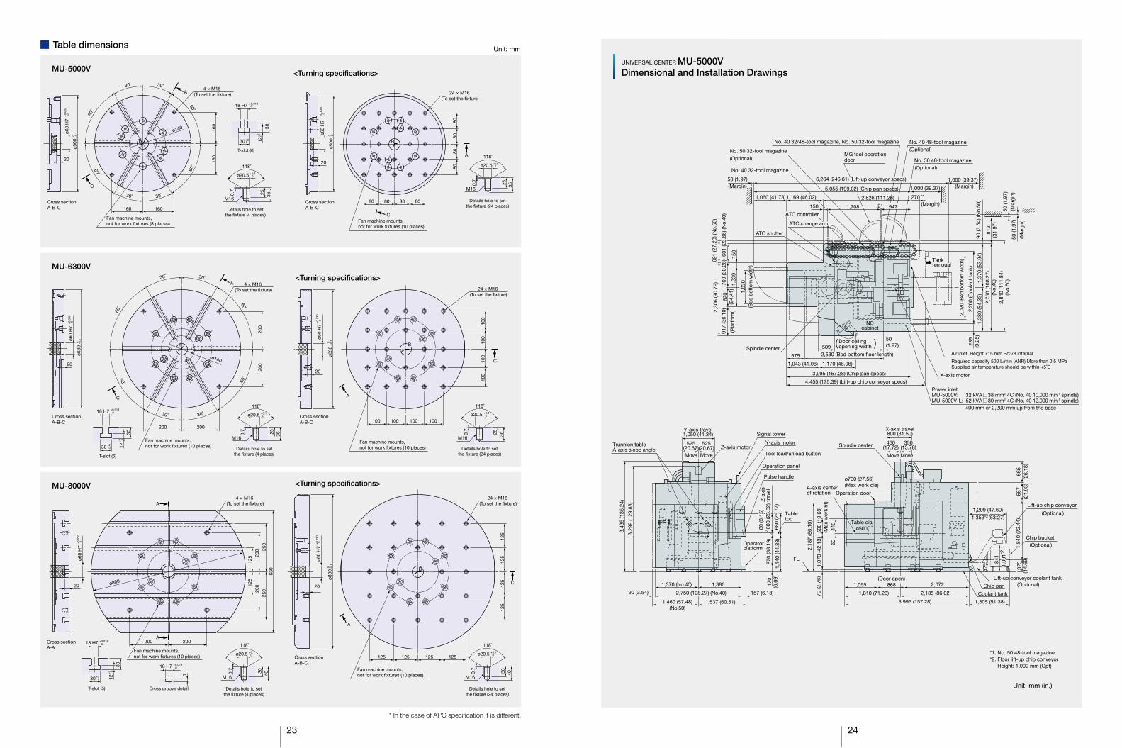
Unit: mm (in.)
UNIVERSAL CENTER MU-5000VDimensional and Installation Drawings
MG tool operationdoor
(Optional)
(Optional)
(Margin)
Spindle center
No. 40 48-tool magazine
5,055 (199.02) (Chip pan specs)
(Optional)No. 50 48-tool magazine
TankremoualTankremoual
No. 40 32/48-tool magazine, No. 50 32-tool magazine
*1
No. 50 32-tool magazine
No. 40 32-tool magazine
2,30
6 (9
0.79
) 1,23
9
1,03
0
150
601
(23.
66) (
No.
40)
769
(30.
28)
601
(23.
66) (
No.
40)
MU-5000V: 32 kVA 38 mm2 4C (No. 40 10,000 min-1 spindle)MU-5000V-L: 52 kVA 80 mm2 4C (No. 40 12,000 min-1 spindle)
2,84
0 (1
11.8
4)(N
o.50
)
2,75
0 (1
08.2
7)(N
o.40
)
1,38
0 (5
4.33
)
235
(9.2
5)1,
370
(53.
94)
50 (1
.97)
(Pla
tfor
m)
(Bed
bot
tom
wid
th)
(Bed
bot
tom
wid
th)
50(1.97)
3,995 (157.28) (Chip pan specs)
4,455 (175.39) (Lift-up chip conveyor specs)
1,170 (46.06)1,043 (41.06)
575 2,530 (Bed bottom floor length)2,530 (Bed bottom floor length)509
Door ceilingopening widthDoor ceilingopening width
NCcabinet
2,02
0 (B
ed b
otto
m w
idth
)
2,20
0 (C
oola
nt t
ank)
769
(30.
28)
620
(24.
41)
917
(36.
10)
ATC change arm
ATC controller
ATC change arm
ATC controller
ATC shutter
50 (1.97)
1,060 (41.73) 2,826 (111.26)
150 1,708
X-axis motor
Power inlet
400 mm or 2,200 mm up from the base
270
(Margin)
(Margin)
(Mar
gin)
50 (1
.97)
(Mar
gin)
812
(31.
97)
1,000 (39.37)
1,000 (39.37)
691
(27.
20) (
No.
50)
90 (3
.54)
(No.
50)
90 (3
.54)
(No.
50)
947
Air inlet Height 715 mm Rc3/8 internal
Required capacity 500 L/min (ANR) More than 0.5 MPaSupplied air temperature should be within +5˚C
21
1,460 (57.48)(No.50)
1,370 (No.40)
1,14
0 (4
4.88
)
3,29
9 (1
29.8
8)
3,43
5 (1
35.2
4)
680
(26.
77)
600
(23.
62)
80 (3
.15)
680
(26.
77)
600
(23.
62)
80 (3
.15)
970
(38.
19)
170
(6.6
9)
157 (6.18)90 (3.54)
1,537 (60.51)
1,380
Z-a
xis
trav
el
Operation panel
Operatorplatform
Tool load/unload button
Pulse handle
Z-axis motor
Signal tower
Y-axis motorTrunnion table A-axis slope angle
Tabletop
Y-axis travel1,050 (41.34)
MoveMove MoveMove
350(13.78)
450(17.72)
MoveMove
525(20.67)
525(20.67) Spindle center
A-axis centerof rotation Operation door
(Optional)
Lift-up chip conveyor
(Optional)Chip bucket
(Optional)
2,18
7 (8
6.10
)
70 (2
.76)
6044
0
1,07
0 (4
2.13
)
1,055
1,810 (71.26) 2,185 (86.02)
2,072
3,995 (157.28) 1,305 (51.38)
ø700 (27.56)(Max work dia)
Lift-up conveyor coolant tank
Coolant tank
Chip pan
X-axis travel800 (31.50)
350(13.78)
1,209 (47.60)1,209 (47.60)
1,353 (53.27)1,353 (53.27)
1,84
0 (7
2.44
)1,
840
(72.
44)
373
(14.
69)
557
665
(21.
93)
(26.
18)
450(17.72)
Table diaø500
FL
0
120°
841
1,09
184
11,
091*
2
°9
*1. No. 50 48-tool magazine*2. Floor lift-up chip conveyor
Height: 1,000 mm (Opt)
( )
(Door open)868
1,169 (46.02)
6,264 (246.61) (Lift-up conveyor specs)
2,750 (108.27) (No.40)
*2
500
(19.
69)
(Max
wor
k ht
)
■ Table dimensions Unit: mm
MU-5000V
MU-6300V
MU-8000V
30˚
30˚
30˚
30˚
60˚
60˚ 60˚
60˚
160
160
160
Fan machine mounts,not for work fixtures (8 places)
C
A
160
B
ø140
4 × M16 (To set the fixture)
ø60
H7
20
ø500
Cross sectionA-B-C
+0.
030
0
0 -0.1
ø500
0 -0.1
ø20.5
118˚
18 H7
30 +20
+0.0180
12
30
+2
25 36
T-slot (6)
Details hole to setthe fixture (4 places)
M16
ø60
H7
+0.
030
0
20
Cross sectionA-B-C
0
+0.10
<Turning specifications>
118˚
25 35
Details hole to setthe fixture (24 places)
M16
Fan machine mounts,not for work fixtures (10 places)
80
A
C
8080
80
8080 8080
B
+0.10ø20.5
24 × M16 (To set the fixture)
200
ø140
30˚
30˚
30˚
30˚
60˚
60˚ 60˚
60˚
200
200 200
18 H7
30
+0.0180
12
30
+2 0
T-slot (6)
Fan machine mounts,not for work fixtures (10 places)
4 × M16 (To set the fixture)
C
A
B
ø60
H7
ø630
20
Cross sectionA-B-C
<Turning specifications>
ø60
H7
20
Cross sectionA-B-C
ø630
ø20.5
118˚
25 36
+0.10
Details hole to setthe fixture (4 places)
M16
+0.
030
0
-0.1
0
A
100
100
100
100
24 × M16 (To set the fixture)
+0.
030
0
Fan machine mounts,not for work fixtures (10 places)
C
100100100100
−0.
1
B
0
ø20.5
118˚
25 36
+0.10
Details hole to setthe fixture (24 places)
M16
125
125
200
200
250
250
630
20
Fan machine mounts,not for work fixtures (10 places)
ø60
H7
+0.
030
0
Cross sectionA-A
ø20.5
118˚
30 40
+0.10
Details hole to setthe fixture (4 places)
30 +20 12
T-slot (5) Cross groove detail
18 H7 +0.0180
18 H7 +0.0180
4 × M16 (To set the fixture)
A200 200
A
30
+2 0
M16
7
ø800
Cross sectionA-B-C
Details hole to setthe fixture (24 places)
20
ø60
H7
+0.
030
0
ø800
-0.1
0
Fan machine mounts,not for work fixtures (10 places)
24 × M16 (To set the fixture)
ø20.5
118˚
30 40
M16
125
125
125
125
125125125125
A
B
C
+0.10
<Turning specifications>
+20
0.7
0.7
0.7
0.7
0.7
0.7

25 26
UNIVERSAL CENTER MU-6300VDimensional and Installation Drawings
NCcabinet
900 (35.43)
50 (1.97)
1,417 136107 136107
1,922 (75.67) 450(17.72)
255
(10.
04)
420
(16.
54)
255
(10.
04)
683
(26.
89)
683
(26.
89)1,
430
(56.
30)
1,56
0 (6
1.42
)
(Mar
gin)
50(1
.97)
2,32
0 (9
1.34
) (C
oola
nt t
ank)
6,012 (236.69) (Chip pan specs)
6,659 (262.17) (Lift-up conveyor specs)
420
(16.
54)
Tankremoual
1,178 (46.38)[1,608]
1,300 (51.18)(Operator platform)
195 (7.68) [625]
Spindle center
1,03
0(B
ed b
otto
m w
idth
)1,
030
(Bed
bot
tom
wid
th)
2,02
0 (7
9.53
)(B
ed b
otto
m w
idth
)
(Door ceiling opening width)644
(25.35)
(Door ceiling opening width)644
(25.35)
(Optional)
(Pla
tfor
m)
620
(24.
41)
150 202,966 (116.77)
ATC controllerATC controller
ATC shutter
140*1
6,803 (267.83)*2
1,060(41.73)
1,434 (56.46)[1,864] 1,0871,0871,709
No. 50 32-toolmagazine
No. 40 48-tool magazine (Optional) No. 50 48-tool magazine (Optional)
MG tool operationdoor
No. 40 32-toolmagazine
1,000(39.37)
(Margin)50 (1.97)(Margin)
1,300 (Coolant tank)
Required capacity 500 L/min (ANR) More than 0.5 MPaSupplied air temperature should be within +5˚C
952
(37.
48)
2,99
0 (1
17.7
2)(M
argi
n)50
(1.9
7)
X-axis travel925 (36.42) [1,450]
Spindle center
A-axis centerof rotation
Operation door
510
MoveMove
2,325 (91.54)2,075 (81.69) [2,505]
2,212 (87.09)1,188 (46.77)
[1,618]
ø630 (24.80)(Table dia)
ø830 (32.68) (Max work dia)
4,400 (173.23) [4,830] 1,295 (50.98)
2,94
0 (1
15.7
5)
1,84
0 (7
2.44
)
2,94
0 (1
15.7
5)58
5(2
3.03
)
1,84
0 (7
2.44
)72
7(2
8.62
)37
3 (1
4.69
)
841
1,199 (47.20)1,343 (52.87)
2,20
2 (8
6.69
)
1,08
0 (4
2.52
)70
(2.7
6)
100
450
FL
Chip pan
Chip bucket (Optional)
Lift-up chipconveyor (Optional)
4,850 (190.94) [5,280]
Power inletMU-6300V: 37 kVA 38 mm2 4C (No. 40 10,000 min-1 spindle)MU-6300V-L: 53 kVA 80 mm2 4C (No. 40 12,000 min-1 spindle)
400 mm or 2,200 mm up from the base
Air inlet height 866 mm Rc3/8 internal
X-axis motor
Operation panel
Signal tower
Operatorplatform
Table top
1,15
0 (4
5.28
)76
0 (2
9.92
)76
0 (2
9.92
)
900
(35.
43)16
025
0(9
.84)
Pulsehandle
Tool load/unload button
3,38
9 (1
33.4
3)
3,52
5 (1
38.7
8)
1,430 (56.30) 197 (7.76)1,560 (61.42)
3,187 (125.47)
Y-axis travel1,050 (41.34)
525(20.67)Move Move
525(20.67)
100 ATC movement
Trunnion table A-axis slope angle
Y-axis motor
Z-axis motor
90° 120°
1,00
7(3
9.65
)1,
239
(48.
78)
150
(5.9
1)
769
(30.
28)
791
(31.
14)
[ ] X-axis extension specifications (APC)*1. No. 50 48-tool magazine*2. Floor lift-up chip conveyor
Height: 1,000 mm (Opt)
UNIVERSAL CENTER MU-8000VDimensional and Installation Drawings
32 toolmagazine (No. 50)(optional)
5,280 (207.87)
1,300 (Platform)
857
625(24.61)
900 (35.43)
50 (1.97)
1,608(63.31)
1,922 (75.67)
3,305 (130.12) (Bed bottom floor length)
1,300 (Coolant tank)
450(17.72)
1361,417107
255
(10.
04)
255
(10.
04)
683
(26.
89)
952
(37.
48)
1,43
0 (5
6.30
)
620
(24.
41)
769
(30.
28)
791
(31.
14)
1,23
9 (4
8.78
)15
0 (5
.91)
1,00
7(3
9.65
)(P
latf
orm
)
2,99
0 (1
17.7
2)
1,56
0 (6
1.42
)
2,32
0 (9
1.34
) (C
oola
nt t
ank)
420
(16.
54)
420
(16.
54)
2,02
0 (7
9.53
)(B
ed b
otto
m w
idth
)
50 (1
.97)
(Mar
gin)
(Margin)1,060 (41.73) 1,864 (73.39) 2,966 (116.77)
1,709 1,087150 20
50 (1.97)(Margin)
50 (1
.97)
(Mar
gin)
Tankremoval
6,442 (253.62) (Chip pan specs)
7,089 (279.09) (Lift-up chip conveyor specs)
ATC controller
ATC change arm
ATC shutter
32 toolmagazine (No. 40)
No. 50 48-tool magazine (Optional)
No. 40 48-tool magazine (Optional)
Door ceilingopening widthDoor ceiling
opening widthSpindle center
Power inletMU-8000V: 37 kVA 38 mm2 4C (No. 40 10,000 min-1 spindle)MU-8000V-L: 53 kVA 80 mm2 4C (No. 40 12,000 min-1 spindle)
400 mm or 2,200 mm up from the base
Air inlet Height 866 mm Rc3/8 internal
Required capacity 500 L/min (ANR) More than 0.5 MPaSupplied air temperature should be within +5˚C
NCcabinet
600
(23.
62) Z
-axi
s tr
avel
800
(31.
50)
1,21
0(4
7.64
)
960
(37.
80)
250
(9.8
4)20
0 (7
.87)
Operation panel
Signal tower
Tool load/unload button
Y-axis motorZ-axis motor
100 ATC movement
Trunnion table A-axis slope angle
Operatorplatform
Table top
Pulsehandle
3,48
9 (1
37.3
6)
3,62
5 (1
42.7
2)
1,050 (41.34)Y-axis travel
1,560 (61.42) 1,430 (56.30) 197(7.76)
3,187 (125.47)
925 (36.42)X-axis travel
Chip bucket(Optional)
2,325 (91.54)2,505 (98.62)
2,212 (87.09)1,411 (55.55)Coolant tank
Chip pan
2,20
2 (8
6.69
)
FL
1,295 (50.98)4,830 (190.16)
Spindle center
Operation door
ø1,000 (39.37) (Max work dia)
(Door open)1,207 (47.52)
Table dia ø800
A-axis centerof rotation
1,14
0 (4
4.88
)
80 (3
.15)
470
70 (2
.76)
90° 120°
2,94
0 (1
15.7
5)68
5(2
6.97
)
1,84
0 (7
2.44
)72
7(2
8.62
)37
3
Lift-up chip conveyor(Optional)
1,199 (47.20)
1,09
184
1
*1. No. 50 48-tool magazine*2. Floor lift-up chip conveyor
Height: 1,000 mm (Opt)
Unit: mm (in.)Unit: mm (in.)
1,000(39.37)
(Margin)
ATC change arm
3,305 (130.12) (Bed bottom floor length)
600
(23.
62)
Z-a
xis
trav
el
550
(21.
65)
(Max
wor
k ht
)
415(16.34)
(20.08) [1,035]
(Door open)1,000 (39.37)
Coolant tank
*2
1,09
1*2
1,03
0 (4
0.55
)(B
ed b
otto
m w
idth
)
140*1
1,000(39.37)
(Margin)1,000(39.37)
MG tool operation door
X axis motor
525(20.67)Move Move
Move
525(20.67)
550
(21.
65)
(Max
wor
k he
ight
)
(31.50)
415510(16.34)(20.08)Move
*2
1,353 (53.27)
1,343 (52.87)*2

Oguchi-cho, Niwa-gun,Aichi 480-0193, JapanTEL: +81-587-95-7825 FAX: +81-587-95-6074
This product is subject to the Japanese government Foreign Exchange and Foreign Trade Control Act with regard to security controlled items; whereby Okuma Corporation should be notified prior to its shipment to another country.
When using O
kuma p
roducts, alw
ays read the safety p
recautionsm
entioned in the instruction m
anual and attached
to the prod
uct.
� The sp
ecifications, illustrations, and d
escriptions in this b
rochure vary in different m
arkets andare sub
ject to change without notice.
Pub
No. M
U-V
series-E-(3a)-400 (Feb
2016)


