13
Vertical Machining Centers
| Date post: | 24-May-2018 |
| Category: |
Documents |
| Upload: | truongxuyen |
| View: | 225 times |
| Download: | 1 times |
Vertical Machining Centers
����
1 21 2
Vertical Machining Centers
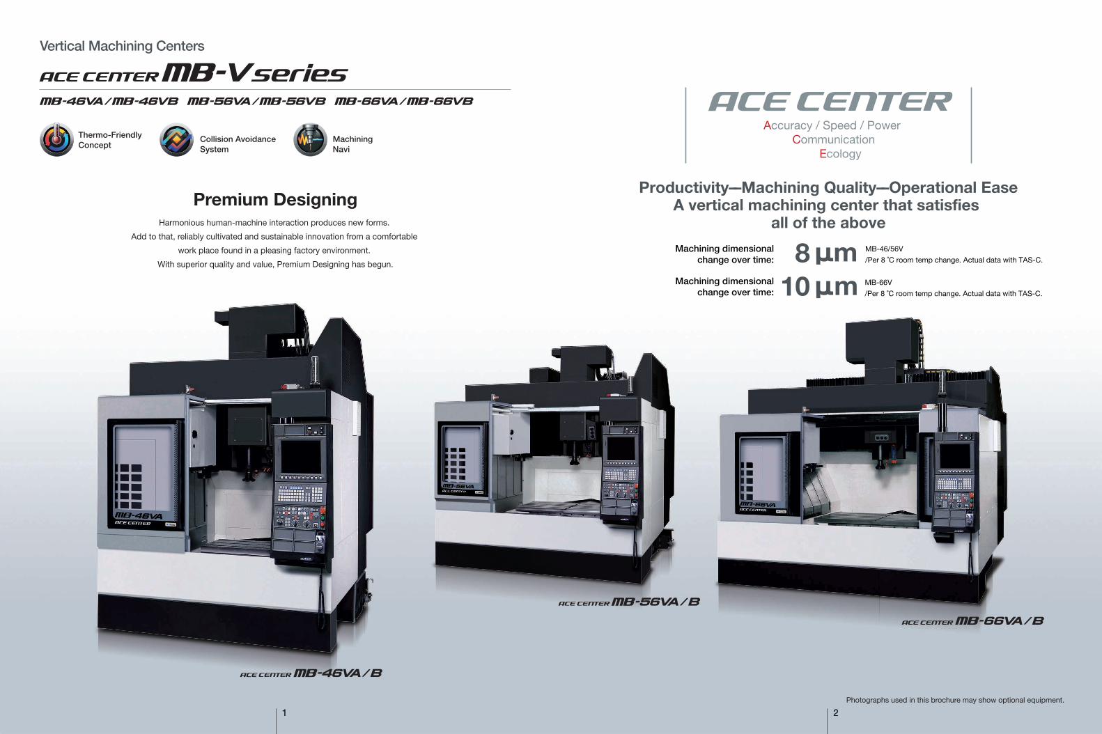
Productivity––Machining Quality––Operational EaseA vertical machining center that satisfies
all of the aboveMB-46/56V
/Per 8 ˚C room temp change. Actual data with TAS-C.mMB-66V
/Per 8 ˚C room temp change. Actual data with TAS-C.m
Photographs used in this brochure may show optional equipment.
Thermo-FriendlyConcept
MachiningNavi
Collision AvoidanceSystem
Accuracy / Speed / PowerCommunication
Ecology
Machining dimensionalchange over time:
Machining dimensionalchange over time:
810
Harmonious human-machine interaction produces new forms.
Add to that, reliably cultivated and sustainable innovation from a comfortable
work place found in a pleasing factory environment.
With superior quality and value, Premium Designing has begun.
Premium Designing
3 4
With PrecisionAccuracy
Parts machined with higher quality
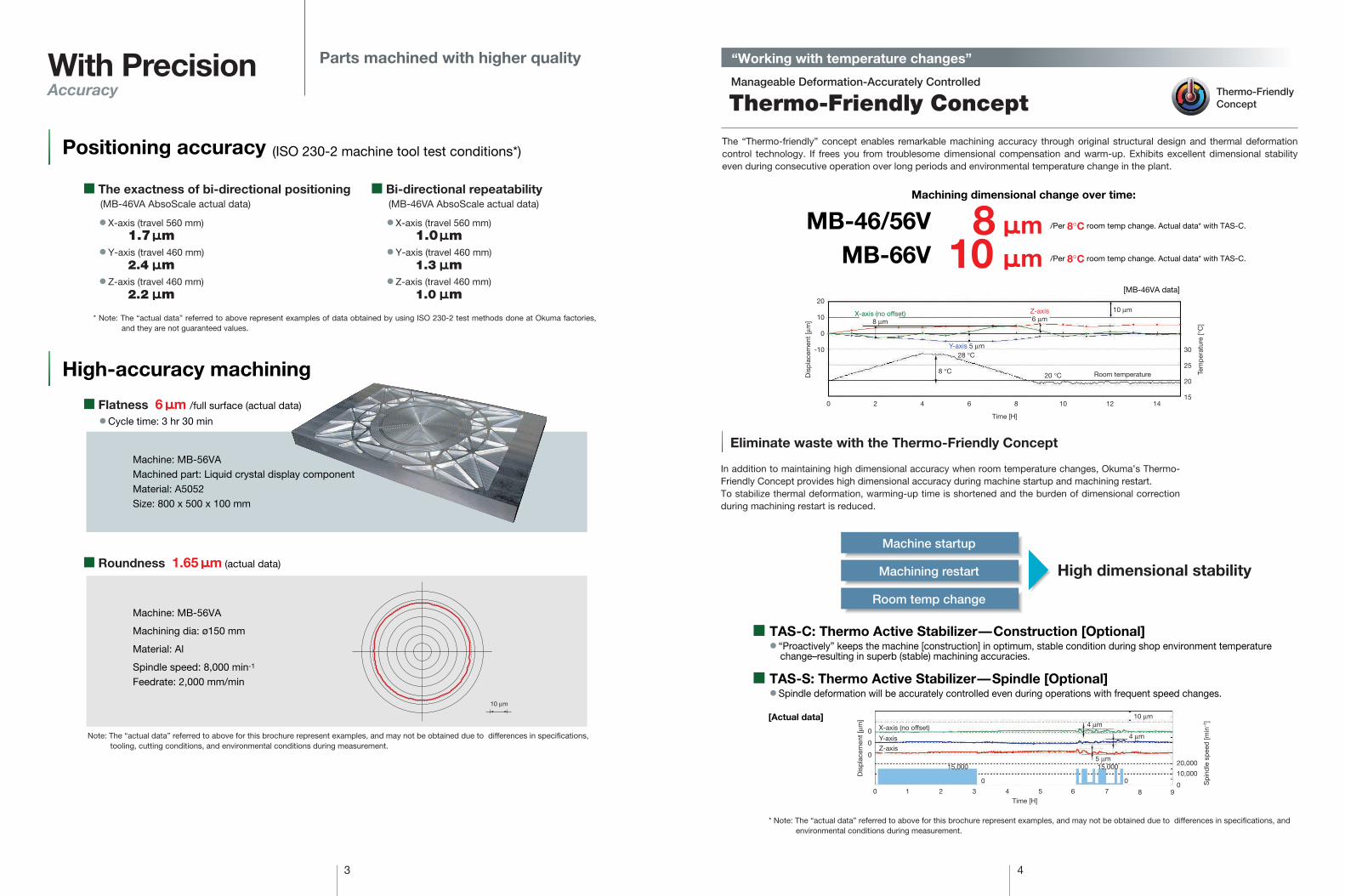
The “Thermo-friendly” concept enables remarkable machining accuracy through original structural design and thermal deformation control technology. If frees you from troublesome dimensional compensation and warm-up. Exhibits excellent dimensional stability even during consecutive operation over long periods and environmental temperature change in the plant.
Manageable Deformation-Accurately Controlled
Thermo-Friendly Concept
“Working with temperature changes”
Thermo-FriendlyConcept
MB-46/56V
� TAS-C: Thermo Active Stabilizer—Construction [Optional]� “Proactively” keeps the machine [construction] in optimum, stable condition during shop environment temperature
change–resulting in superb (stable) machining accuracies.
� TAS-S: Thermo Active Stabilizer—Spindle [Optional]� Spindle deformation will be accurately controlled even during operations with frequent speed changes.
[MB-46VA data]
[Actual data]
/Per 8°C room temp change. Actual data* with TAS-C.
MB-66V /Per 8°C room temp change. Actual data* with TAS-C.
Machine: MB-56VAMachined part: Liquid crystal display componentMaterial: A5052Size: 800 x 500 x 100 mm
Machine: MB-56VA
Machining dia: ø150 mm
Material: Al
Spindle speed: 8,000 min-1
Feedrate: 2,000 mm/min
� Cycle time: 3 hr 30 min
Eliminate waste with the Thermo-Friendly Concept
In addition to maintaining high dimensional accuracy when room temperature changes, Okuma’s Thermo-Friendly Concept provides high dimensional accuracy during machine startup and machining restart.To stabilize thermal deformation, warming-up time is shortened and the burden of dimensional correction during machining restart is reduced.
High dimensional stabilityMachining restart
Room temp change
Machine startup
10 µm
Time [H]
0 2 4 6 8 10 12 14
Dis
pla
cem
ent
[µm
]
Tem
per
atur
e [°
C]
-10 30
25
20
15
0
10
20
X-axis (no offset)8 µm
Z-axis6 µm
10 µm
Room temperature
Y-axis 5 µm28 °C
20 °C8 °C
Dis
pla
cem
ent
[µm
]
0
0
0
1 2 3 4Time [H]
5 6 7 8
10 µm4 µm
4 µm
5 µm
90
010,000
20,000
0
0 X-axis (no offset)
Y-axis
Z-axis
15,000 15,000
Sp
ind
le s
pee
d [m
in-1
]
Machining dimensional change over time:
Note: The “actual data” referred to above for this brochure represent examples, and may not be obtained due to differences in specifications, tooling, cutting conditions, and environmental conditions during measurement.
* Note: The “actual data” referred to above for this brochure represent examples, and may not be obtained due to differences in specifications, and environmental conditions during measurement.
� The exactness of bi-directional positioning � Bi-directional repeatability(MB-46VA AbsoScale actual data) (MB-46VA AbsoScale actual data)
� X-axis (travel 560 mm)1.7 m
� Y-axis (travel 460 mm)2.4 m
� Z-axis (travel 460 mm)2.2 m
� X-axis (travel 560 mm)1.0 m
� Y-axis (travel 460 mm)1.3 m
� Z-axis (travel 460 mm)1.0 m
8 m10 m
Positioning accuracy (ISO 230-2 machine tool test conditions*)
� Flatness 6 m /full surface (actual data)
High-accuracy machining
� Roundness 1.65 m (actual data)
* Note: The “actual data” referred to above represent examples of data obtained by using ISO 230-2 test methods done at Okuma factories, and they are not guaranteed values.

5 6
FastSpeed
During positioning, this function controls the acceleration/deceleration speed according to the speed-torque characteristics of the BL motor, resulting in high-speed and highly stable positioning. The Hi-G control function reduces positioning time and greatly reduces non-cutting time.
� Acceleration Max 0.7 G
� Rapid traverse 40 m/min (1,575 ipm) (X-Y)
� ATC time (T-T) 1.2 sec (MB-46/56VA)
1.5 sec (MB-66VA)
� Spindle accel/decel 1.2 sec (0↔8,000 min-1)
� High-speed spindle MB-VA (No.40) 8,000 min-1 (Std)
15,000 / 20,000
25,000 / 35,000* min-1 (Opt)
MB-VB (No.50) 6,000 min-1 (Std)
12,000 min-1 (Opt)
� Cutting speed 32 m/min (1,260 ipm)
� Hi-G Control (standard)
This controls the feedrate to provide machining suitable for corner shapes and circular shapes of machining parts, with the aim of ensuring high-accuracy machining and reducing cycle time.
This function is indispensable for die/mold machining. It is greatly effective in reducing cycle time and improving quality. Moreover, with the addition of AbsoScale (Optional), it can achieve further improvement.
for general machining
for die/mold machining & general machining
� Hi-Cut Pro function (standard)
A worldwide first, Super-NURBS is a high-speed NC function with specially developed speed control functions for processingcurved surfaces. Super-NURBS gives you high-speed, high-accuracy and high-quality machining for any shape, ranging from machine parts to complex curves.
� Super-NURBS (Optional)
� Before � Super-NURBS
Shaping feedrates much faster
Much faster acceleration
Super-NURBS takes the machining program's command path and calculates a path that provides smoother tool movement and has less impact on the machine.
Machining along this smoother path means that acceleration and deceleration of the tool movement can be controlled, and greatly reduces the shock and oscillation on the machine and drive unit during high-speed feeding.
This improved speed control results in more efficient machining at the machine's maximum speed.
35% less non-cutting time (MB-46VA: Compared to previous Okuma machine) 30% faster cutting time (Compared to previous Okuma machine)
Without Hi-Cut Pro With Hi-Cut Pro
High productivity per faster cycle times
Process time comparison
Sample workpiece
Previous machine
MB-46VAACE CENTER
35% less
Non cutting timeCutting time
85 sec
3.5 min
3.5 min
131 sec
35%� No. of tools used: 4 tools in 1st operation
6 tools in 2nd operation� Workpiece size: 350 x 200 x 60 mm
(13.78 x 7.87 x 2.36 in.)Note: Per same program, and no change in cutting time.
� With Hi-Cut ProSharp corner edges
� Without Hi-Cut Pro Drooped corners
� Hi-Cut Pro result
Feed
rate
Feed
rate
* Not availale for MB-66VA
Time
Speed
Previous
Reduced positioning time
Hi-G control
7 8
Strong/RigidPower
[Actual data*]
Cutting capacities:
� Powerful cutting examples
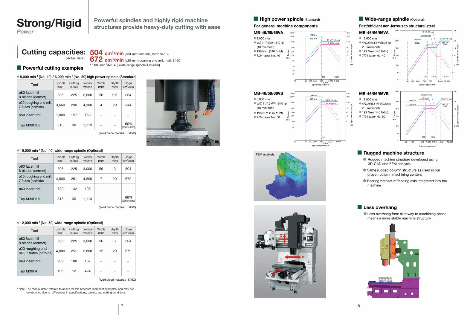
� High power spindle (Standard) � Wide-range spindle (Optional)
10 50 100 200 5001,000
5,0002,000
8,000
2
3
5
10
20
30
50
100
200
300
1
2
3
5
10
20
30
530
198 N-m
135 N-m11 kW (10 min)
7.5 kW (cont)
MB-46/56/66VA� 8,000 min-1
� VAC 11/7.5 kW (15/10 hp)(10 min/cont)
� 198 N-m (146 ft-lbf)� 7/24 taper No. 40
MB-46/56/66VA� 15,000 min-1
� VAC 22/18.5 kW (30/25 hp)(10 min/cont)
� 199 N-m (146 ft-lbf)� 7/24 taper No. 40
10,0004,0001,000500
720 2,500 15,000
200100505
10
20
50
100
200
500
1
2
5
10
20
50
199 N-m
146 N-m
22 kW (10 min)
15 kW (10 min)
18.5 kW (cont)
11 kW (cont)
� Rugged machine structure developed using3D-CAD and FEM analysis
� Same rugged column structure as used in our proven column machining centers
� Bearing bracket of feeding axis integrated into the machine
� Rugged machine structure
� Less overhang from slideway to machining phase means a more stable machine structure
� Less overhang
X
Z
Y
* Note: The “actual data” referred to above for this brochure represent examples, and may not be obtained due to differences in specifications, tooling, and cutting conditions.
(Workpiece material: S45C)
(Workpiece material: S45C)
(Workpiece material: S45C)
� 8,000 min-1 (No. 40) / 6,000 min-1 (No. 50) high power spindle (Standard)
ø80 face mill 8 blades (cermet)
ø20 roughing end mill,7 flutes (carbide)
Tool
895
3,660
1,000
318
225
230
157
30
2,600
4,300
150
1,113
56
4
–
–
2.5
20
–
–
364
344
–
Spindlemin-1
Cuttingm/min
Feedratemm/min
Widthmm
Depthmm
Chipscm3/min
For general machine components Fast/efficient non-ferrous to structural steel
MB-46/56/66VB� 6,000 min-1
� VAC 11/7.5 kW (15/10 hp)(10 min/cont)
� 198 N-m (146 ft-lbf)� 7/24 taper No. 50
MB-46/56/66VB� 12,000 min-1
� VAC 26/18.5 kW (29/25 hp)(10 min/cont)
� 199 N-m (146 ft-lbf)� 7/24 taper No. 50
5
10
20
50
100
200
500
1
2
5
10
20
50
12,0002,0001,000500 4,00010050
720 2,500
199 N-m
146 N-m 18.5 kW (cont)
26 kW (10 min)
15 kW (10 min)
11 kW (cont)
Powerful spindles and highly rigid machine structures provide heavy-duty cutting with ease
(ø80-mm face mill, matl: S45C)
(ø20-mm roughing end mill, matl: S45C)
15,000 min-1 (No. 40) wide-range spindle (Optional)
N-m
kW
Torq
ue
N-m
Torq
ue
Sp
ind
le m
otor
out
put
N-m
kW
Torq
ue
Sp
ind
le m
otor
out
put
kW
Sp
ind
le m
otor
out
put
Spindle speed min-1 Spindle speed min-1
N-m
kW
Torq
ue
Sp
ind
le m
otor
out
put
Spindle speed min-1Spindle speed min-1
FEM analysis
ø50 insert drill
Tap M30P3.5
� 15,000 min-1 (No. 40) wide-range spindle (Optional)
ø80 face mill 8 blades (cermet)
ø20 roughing end mill,7 flutes (carbide)
Tool
895
4,000
720
318
225
251
142
30
3,000
4,800
108
1,113
56
7
–
–
3
20
–
–
504
672
–
Spindlemin-1
Cuttingm/min
Feedratemm/min
Widthmm
Depthmm
Chipscm3/min
ø63 insert drill
Tap M30P3.5
� 12,000 min-1 (No. 50) wide-range spindle (Optional)
ø80 face mill 8 blades (cermet)
ø20 roughing end mill, 7 flutes (carbide)
Tool
895
4,000
909
106
225
251
180
12
3,000
2,800
137
424
56
12
–
–
3
20
–
–
504
672
–
–
Spindlemin-1
Cuttingm/min
Feedratemm/min
Widthmm
Depthmm
Chipscm3/min
ø63 insert drill
Tap M36P4
504 cm3/min 672 cm3/min
60%(Spindle load)
66%(Spindle load)
10 50 100 200 5001,000
2,000 6,000
5
10
20
30
50
100
200
300
1
2
3
5
10
20
30
530
198 N-m
135 N-m 11 kW (10 min)
7.5 kW (cont)
9 10
Communication
Getting the best from human operators and advanced machine tools
Human-machineinteraction
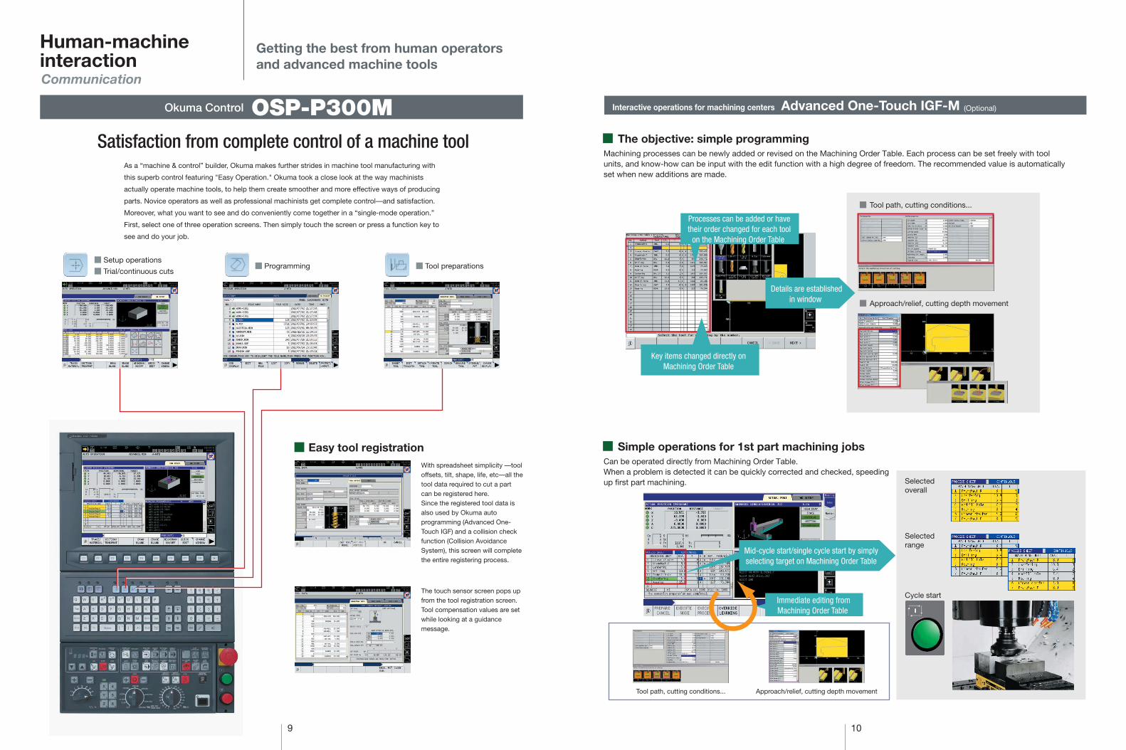
Satisfaction from complete control of a machine tool
� Setup operations
� Trial/continuous cuts� Programming � Tool preparations
As a “machine & control” builder, Okuma makes further strides in machine tool manufacturing with
this superb control featuring "Easy Operation." Okuma took a close look at the way machinists
actually operate machine tools, to help them create smoother and more effective ways of producing
parts. Novice operators as well as professional machinists get complete control—and satisfaction.
Moreover, what you want to see and do conveniently come together in a “single-mode operation.”
First, select one of three operation screens. Then simply touch the screen or press a function key to
see and do your job.
With spreadsheet simplicity —tool offsets, tilt, shape, life, etc—all the tool data required to cut a part can be registered here.Since the registered tool data is also used by Okuma auto programming (Advanced One-Touch IGF) and a collision check function (Collision Avoidance System), this screen will complete the entire registering process.
The touch sensor screen pops up from the tool registration screen. Tool compensation values are set while looking at a guidance message.
Okuma Control OSP-P300M
Easy tool registration
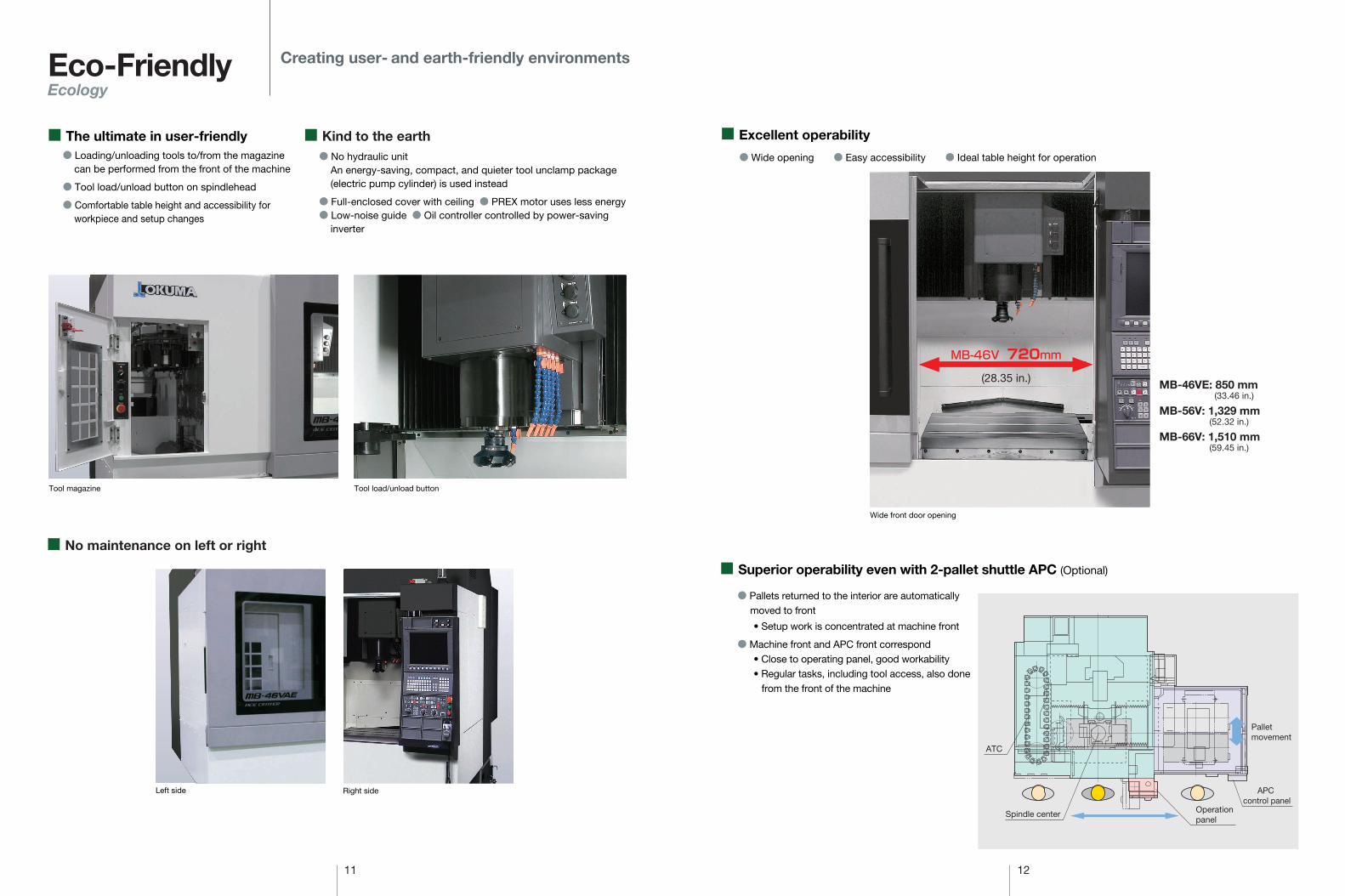
Interactive operations for machining centers
Machining processes can be newly added or revised on the Machining Order Table. Each process can be set freely with tool units, and know-how can be input with the edit function with a high degree of freedom. The recommended value is automatically set when new additions are made.
Can be operated directly from Machining Order Table.When a problem is detected it can be quickly corrected and checked, speeding up first part machining.
� Tool path, cutting conditions...
� Approach/relief, cutting depth movement
Selectedoverall
Selectedrange
Cycle start
Tool path, cutting conditions... Approach/relief, cutting depth movement
(Optional) Advanced One-Touch IGF-M
� The objective: simple programming
� Simple operations for 1st part machining jobs
Key items changed directly on Machining Order Table
Mid-cycle start/single cycle start by simply selecting target on Machining Order Table
Immediate editing from Machining Order Table
Details are established in window
Processes can be added or have their order changed for each tool
on the Machining Order Table
Left side Right side
� No maintenance on left or right
Tool load/unload buttonTool magazine
11 12
Eco-FriendlyEcology
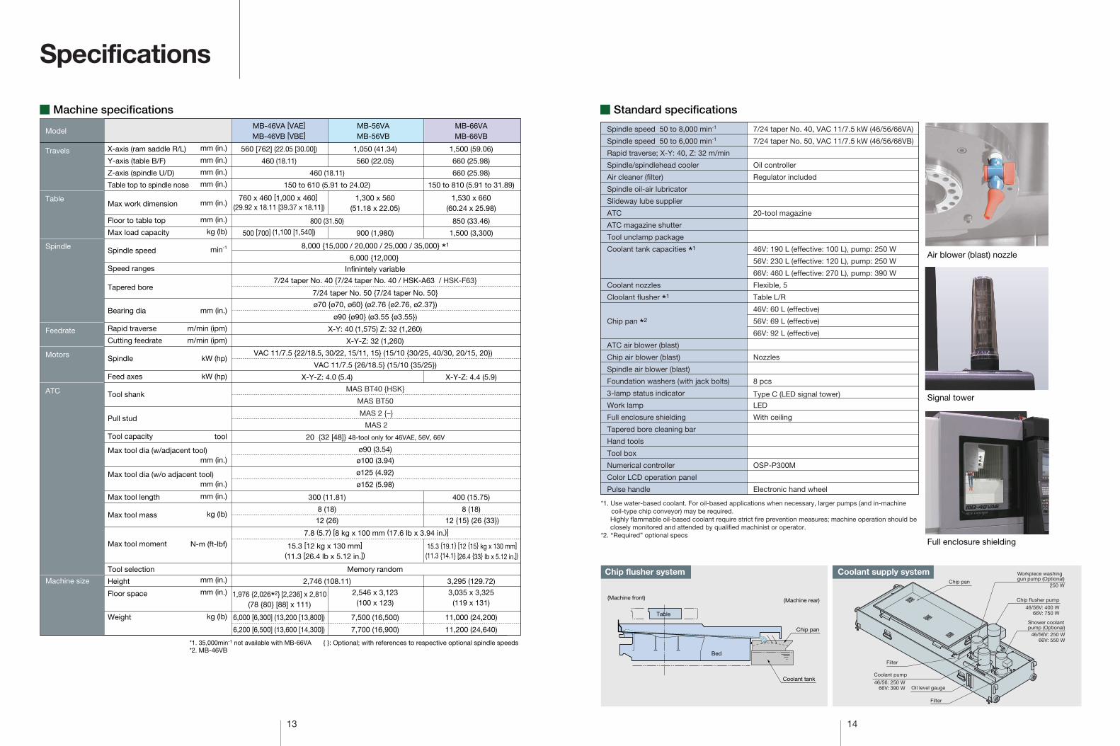
� Excellent operability
� Wide opening � Easy accessibility � Ideal table height for operation
� Pallets returned to the interior are automatically moved to front
• Setup work is concentrated at machine front
� Machine front and APC front correspond• Close to operating panel, good workability• Regular tasks, including tool access, also done
from the front of the machine
� The ultimate in user-friendly� Loading/unloading tools to/from the magazine
can be performed from the front of the machine
� Tool load/unload button on spindlehead
� Comfortable table height and accessibility for workpiece and setup changes
� Kind to the earth� No hydraulic unit
An energy-saving, compact, and quieter tool unclamp package (electric pump cylinder) is used instead
� Full-enclosed cover with ceiling � PREX motor uses less energy� Low-noise guide � Oil controller controlled by power-saving
inverter
Wide front door opening
MB-46VE: 850 mm (33.46 in.)
MB-56V: 1,329 mm(52.32 in.)
MB-66V: 1,510 mm(59.45 in.)
APC control panel
Spindle center
ATC
Palletmovement
� Superior operability even with 2-pallet shuttle APC (Optional)
Creating user- and earth-friendly environments
(28.35 in.)
Operation panel
13 14
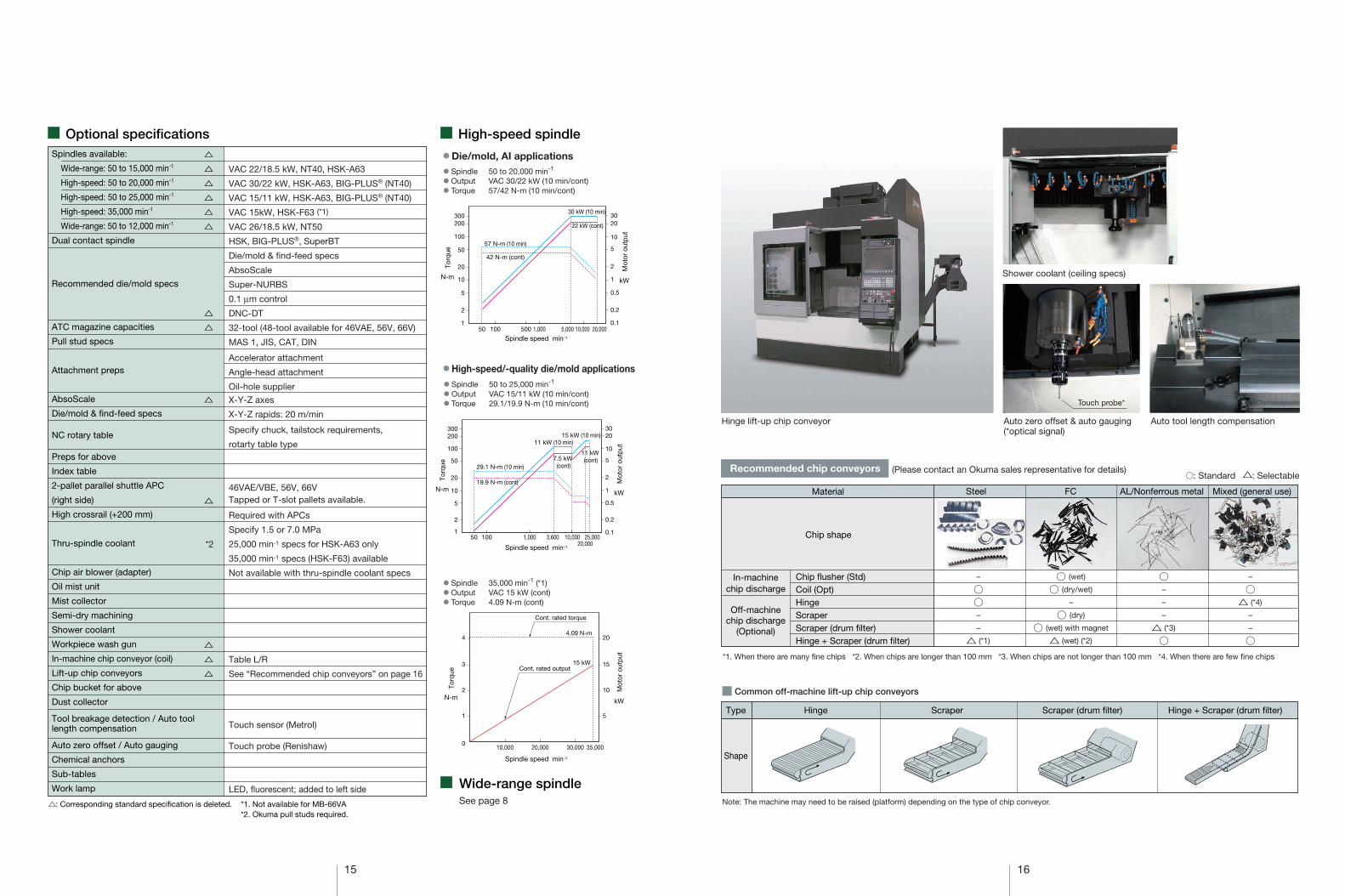
� Machine specifications � Standard specifications
Specifications
{ }: Optional; with references to respective optional spindle speeds*1. 35,000min-1 not available with MB-66VA
560 [762] (22.05 [30.00])
MB-46VA [VAE]
MB-46VB [VBE]MB-56VAMB-56VB
460 (18.11)
460 (18.11)
X-Y: 40 (1,575) Z: 32 (1,260)
X-Y-Z: 32 (1,260)
X-Y-Z: 4.0 (5.4) X-Y-Z: 4.4 (5.9)
20 {32 [48]} 48-tool only for 46VAE, 56V, 66V
Memory random
2,746 (108.11) 3,295 (129.72)
800 (31.50)
500 [700] (1,100 [1,540])
8,000 {15,000 / 20,000 / 25,000 / 35,000} *1
6,000 {12,000}
VAC 11/7.5 {22/18.5, 30/22, 15/11, 15} (15/10 {30/25, 40/30, 20/15, 20})
VAC 11/7.5 {26/18.5} (15/10 {35/25})
ø90 (3.54)
ø100 (3.94)
ø125 (4.92)
ø152 (5.98)
300 (11.81)
8 (18)
12 (26)
15.3 [12 kg x 130 mm] (11.3 [26.4 lb x 5.12 in.])
1,976 {2,026*2} [2,236] x 2,810(78 {80} [88] x 111)
6,000 [6,300] (13,200 [13,800])
6,200 [6,500] (13,600 [14,300])
1,050 (41.34)
560 (22.05)
1,300 x 560(51.18 x 22.05)
900 (1,980)
2,546 x 3,123(100 x 123)
7,500 (16,500)
7,700 (16,900)
MB-66VAMB-66VB
660 (25.98)
1,500 (59.06)
660 (25.98)
150 to 810 (5.91 to 31.89)
1,530 x 660(60.24 x 25.98)
850 (33.46)
1,500 (3,300)
7/24 taper No. 40 {7/24 taper No. 40 / HSK-A63 / HSK-F63}
7/24 taper No. 50 {7/24 taper No. 50}
ø70 {ø70, ø60} (ø2.76 {ø2.76, ø2.37})
ø90 {ø90} (ø3.55 {ø3.55})
MAS BT40 {HSK}
MAS BT50
MAS 2 {–}
MAS 2
8 (18)
12 {15} (26 {33})
400 (15.75)
15.3 {19.1} [12 {15} kg x 130 mm](11.3 {14.1} [26.4 {33} lb x 5.12 in.])
3,035 x 3,325(119 x 131)
11,000 (24,200)
7.8 (5.7) [8 kg x 100 mm (17.6 lb x 3.94 in.)]
11,200 (24,640)
X-axis (ram saddle R/L)
Y-axis (table B/F)
Z-axis (spindle U/D)
Table top to spindle nose
Max work dimension
Floor to table top
Max load capacity
Spindle speed
Speed ranges
Tapered bore
Bearing dia
Rapid traverse
Cutting feedrate
Spindle
Feed axes
Tool shank
Pull stud
Tool capacity
Max tool dia (w/adjacent tool)
Max tool dia (w/o adjacent tool)
Max tool length
Max tool mass
Max tool moment
Tool selection
Height
Floor space
Weight
mm (in.)
mm (in.)
mm (in.)
mm (in.)
mm (in.)
mm (in.)
kg (lb)
min-1
mm (in.)
m/min (ipm)
m/min (ipm)
kW (hp)
kW (hp)
tool
mm (in.)
mm (in.)
mm (in.)
kg (lb)
N-m (ft-lbf)
mm (in.)
mm (in.)
kg (lb)
Infinintely variable
*2. MB-46VB
150 to 610 (5.91 to 24.02)
760 x 460 [1,000 x 460] (29.92 x 18.11 [39.37 x 18.11])
Model
Travels
Table
Spindle
Feedrate
Motors
ATC
Machine size
Spindle speed 50 to 8,000 min-1
Spindle speed 50 to 6,000 min-1
Rapid traverse; X-Y: 40, Z: 32 m/min
Spindle/spindlehead cooler
Air cleaner (filter)
Spindle oil-air lubricator
Slideway lube supplier
ATC
ATC magazine shutter
Tool unclamp package
Coolant tank capacities *1
Coolant nozzles
Cloolant flusher *1
Chip pan *2
ATC air blower (blast)
Chip air blower (blast)
Spindle air blower (blast)
Foundation washers (with jack bolts)
3-lamp status indicator
Work lamp
Full enclosure shielding
Tapered bore cleaning bar
Hand tools
Tool box
Numerical controller
Color LCD operation panel
Pulse handle
7/24 taper No. 40, VAC 11/7.5 kW (46/56/66VA)
7/24 taper No. 50, VAC 11/7.5 kW (46/56/66VB)
Oil controller
Regulator included
20-tool magazine
46V: 190 L (effective: 100 L), pump: 250 W
56V: 230 L (effective: 120 L), pump: 250 W
66V: 460 L (effective: 270 L), pump: 390 W
Flexible, 5
Table L/R
46V: 60 L (effective)
56V: 69 L (effective)
66V: 92 L (effective)
Nozzles
8 pcs
Type C (LED signal tower)
LED
With ceiling
OSP-P300M
Electronic hand wheel
*1. Use water-based coolant. For oil-based applications when necessary, larger pumps (and in-machine coil-type chip conveyor) may be required.Highly flammable oil-based coolant require strict fire prevention measures; machine operation should be closely monitored and attended by qualified machinist or operator.
*2. “Required” optional specs
Coolant supply system
(Machine rear)(Machine front)
Chip pan
Coolant tank
Table
Bed
Chip flusher systemChip pan
46/56: 250 W66V: 390 W
Chip flusher pump46/56V: 400 W
66V: 750 W
Shower coolantpump (Optional)
Filter
Filter
Oil level gauge
46/56V: 250 W66V: 550 W
Workpiece washinggun pump (Optional)
250 W
Coolant pump
Signal tower
Full enclosure shielding
Air blower (blast) nozzle
15 16
� Optional specifications
�: Corresponding standard specification is deleted. *1. Not available for MB-66VA*2. Okuma pull studs required.
� Wide-range spindleSee page 8
10,000 20,000 30,000 35,000
5
10
15
20
1
0
2
3
44.09 N-m
15 kWCont. rated output
Cont. rated torque
� High-speed/-quality die/mold applications
� Spindle 50 to 20,000 min-1
� Output VAC 30/22 kW (10 min/cont)� Torque 57/42 N-m (10 min/cont)
� Spindle 50 to 25,000 min-1
� Output VAC 15/11 kW (10 min/cont)� Torque 29.1/19.9 N-m (10 min/cont)
� Die/mold, AI applications
� Spindle 35,000 min-1 (*1)� Output VAC 15 kW (cont)� Torque 4.09 N-m (cont)
10,000 20,0001,000 5,000100 50050
5
10
20
50
100
200
0.5
1
2
10
5
2030
57 N-m (10 min)
42 N-m (cont)
30 kW (10 min)
22 kW (cont)
0.2
0.1
2
1
300
50 1,000 3,600100 10,000 25,00020,000
10
5
2
1
20
50
100
200300
0.1
1
0.5
0.2
2
5
10
2030
29.1 N-m (10 min)
19.9 N-m (cont)
15 kW (10 min)11 kW (10 min)
11 kW (cont)7.5 kW
(cont)
� High-speed spindleSpindles available:
Wide-range: 50 to 15,000 min-1
High-speed: 50 to 20,000 min-1
High-speed: 50 to 25,000 min-1
High-speed: 35,000 min-1
Wide-range: 50 to 12,000 min-1
Dual contact spindle
Recommended die/mold specs
ATC magazine capacities
Pull stud specs
Attachment preps
AbsoScale
Die/mold & find-feed specs
NC rotary table
Preps for above
Index table
2-pallet parallel shuttle APC
(right side)
High crossrail (+200 mm)
Thru-spindle coolant
Chip air blower (adapter)
Oil mist unit
Mist collector
Semi-dry machining
Shower coolant
Workpiece wash gun
In-machine chip conveyor (coil)
Lift-up chip conveyors
Chip bucket for above
Dust collector
Tool breakage detection / Auto toollength compensation
Auto zero offset / Auto gauging
Chemical anchors
Sub-tables
Work lamp
VAC 22/18.5 kW, NT40, HSK-A63
VAC 30/22 kW, HSK-A63, BIG-PLUS® (NT40)
VAC 15/11 kW, HSK-A63, BIG-PLUS® (NT40)
VAC 15kW, HSK-F63 (*1)
VAC 26/18.5 kW, NT50
HSK, BIG-PLUS®, SuperBT
Die/mold & find-feed specs
AbsoScale
Super-NURBS
0.1 µm control
DNC-DT
32-tool (48-tool available for 46VAE, 56V, 66V)
MAS 1, JIS, CAT, DIN
Accelerator attachment
Angle-head attachment
Oil-hole supplier
X-Y-Z axes
X-Y-Z rapids: 20 m/min
Specify chuck, tailstock requirements,
rotarty table type
46VAE/VBE, 56V, 66VTapped or T-slot pallets available.
Required with APCs
Specify 1.5 or 7.0 MPa
25,000 min-1 specs for HSK-A63 only
35,000 min-1 specs (HSK-F63) available
Not available with thru-spindle coolant specs
Table L/R
See “Recommended chip conveyors” on page 16
Touch sensor (Metrol)
Touch probe (Renishaw)
LED, fluorescent; added to left side
N-m
Spindle speed min-1
Spindle speed min-1
Spindle speed min-1
Mot
or o
utp
ut
Torq
ue
kW
N-m
Mot
or o
utp
ut
Torq
ue
kW
N-m
Mot
or o
utp
ut
Torq
ue
kW
Hinge lift-up chip conveyor Auto zero offset & auto gauging(*optical signal)
Auto tool length compensation
Recommended chip conveyors (Please contact an Okuma sales representative for details)
Material
Chip shape
–
��–
–
� (*1)
� (wet)
� (dry/wet)
–
� (dry)
� (wet) with magnet
� (wet) (*2)
�–
–
–
� (*3)
�
–
�� (*4)
–
–
�
� Common off-machine lift-up chip conveyors
Type
Shape
Hinge Scraper Scraper (drum filter) Hinge + Scraper (drum filter)
�: Standard �: Selectable
Chip flusher (Std)Coil (Opt)HingeScraperScraper (drum filter)Hinge + Scraper (drum filter)
Steel FC AL/Nonferrous metal Mixed (general use)
*1. When there are many fine chips *2. When chips are longer than 100 mm *3. When chips are not longer than 100 mm *4. When there are few fine chips
Note: The machine may need to be raised (platform) depending on the type of chip conveyor.
�
�
�
�
�
�
�
�
�
�
�
�
�
*2
Shower coolant (ceiling specs)
Touch probe*
In-machinechip discharge
Off-machinechip discharge
(Optional)
17 18
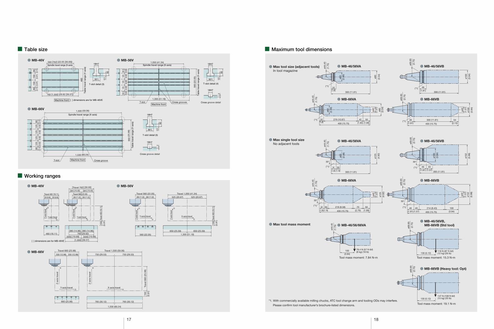
� Table size � Maximum tool dimensions
� Working ranges
Spindle travel range (X-axis)560 [762] (22.05 [30.00])
760 [1,000] (29.92 [39.37])
460
1,300 (51.18)
T-slot detail (3)
18H7
30
30+2 0 12
+2 0
T-slot detail (4)
18H7
30
30+2 0 12
+2 0
Cross groove detail
18H7
7
� MB-46V
� MB-66V
� MB-56V
T-slot detail (5)
18H7
30
30+2 0 12
+2 0
Cross groove detail
18H7
7
� MB-66V
� MB-46V � MB-56V
� MB-46/56VA � MB-46/56VB
� MB-66VA � MB-66VB
� MB-46/56VB
� MB-66VA � MB-66VB
� MB-46/56/66VA� MB-46/56VB,
MB-66VB (Std tool)
� MB-66VB (Heavy tool: Opt)
*1. With commercially available milling chucks, ATC tool change arm and tooling ODs may interfere.
Please confirm tool manufacturer’s brochure-listed dimensions.
(*1)
(*1)
(*1)(*1)
� MB-46/56VA
(*1)
(*1)(*1)
(*1)
80 (3.1
5)15
0(5
.91)
150
(5.9
1)80 (3.1
5)
Machine front [ ] dimensions are for MB-46VE
92.5
(3.6
4)12
5(4
.92)
125
(4.9
2)12
5(4
.92)
92.5
(3.6
4)
Spindle travel range (X-axis)1,050 (41.34)
Cross groovesT-slotMachine front
560
(22.
05)
Tab
le t
rave
l ran
ge (Y
-axi
s)
80 (3.1
5)12
5(4
.92)
125
(4.9
2)12
5(4
.92)
80 (3.1
5)12
5(4
.92)
Spindle travel range (X-axis)
1,500 (59.06)
1,530 (60.24)
Cross grooveT-slot Machine front
660
(25.
98)
Tab
le t
rave
l ran
ge (Y
-axi
s)
Tab
le t
rave
l ran
ge (Y
-axi
s)
280 (11.02)280 (11.02)
Y-axis travel
Z-ax
is tra
vel
Travel 560 (22.05)
560 (22.05)
650 (25.59) 650 (25.59)
525 (20.67)525 (20.67)
1,300 (51.18)
X-axis travel
Trav
el 4
60 (1
8.11
)15
0(5
.91)
Z-ax
is tra
vel
Travel 1,050 (41.34)Travel 560 (22.05)280 (11.02)280 (11.02)
Trav
el 4
60 (1
8.11
)
Z-ax
is tra
vel
Y-axis travel
460 (18.11)380 (14.96) 380 (14.96)
760 (29.92) [500] [19.69] [500] [19.69]
[381] [15.00] [381] [15.00] [Travel 762] [30.00]
[1,000] [39.37]
150
(5.9
1)
[ ] dimensions are for MB-46VE
Y-axis travel
Travel 460 (18.11)
Z-ax
is tra
vel
230 (9.06) 230 (9.06)
330 (12.99) 330 (12.99)
Travel 660 (25.98)
765 (30.12) 765 (30.12)
Trav
el 6
60 (2
5.98
)15
0(5
.91)
Travel 1,500 (59.06)
1,530 (60.24)
660 (25.98)
X-axis travelY-axis travel
Z-a
xis
trav
el
Z-a
xis
trav
el
750 (29.53) 750 (29.53)
� Max tool size (adjacent tools)In tool magazine
� Max single tool sizeNo adjacent tools
� Max tool mass moment
ø69.
85(2
.75)
ø100
(3.9
4)
46(1.81)
300 (11.81)
ø90
(3.5
4)
32(1.26)
300 (11.81)
ø44.
45(1
.75)
ø63
(2.4
8)
ø40
(1.5
7)
ø69.
85(2
.75)
ø100
(3.9
4)
46(1.81)
300 (11.81) 54(2.13)400 (15.75)
ø90
(3.5
4)
ø40
(1.5
7)
32(1.26)
276 (10.87) 42(1.65)
50(1.99)400 (15.75)
ø44.
45(1
.75)
ø63
(2.4
8)
ø44.
45(1
.75)
ø63
(2.4
8)
ø125
(4.9
2)
32(1.26)
30(1.18)
30°
300 (11.81)
30°
ø69.
85(2
.75)
ø152
(5.9
8)
ø100
(3.9
4)
46(1.81)
40(1.57)
300 (11.81)
ø40
(1.5
7)
ø40
(1.5
7)
ø44.
45(1
.75)
ø125
(4.9
2)
32(1.26)
30(1.18)
218 (8.58) 70(2.76)
50(1.99)400 (15.75)
ø69.
85(2
.75)
ø152
(5.9
8)
46(1.81)
40(1.57)
214 (8.43) 100(3.94)400 (15.75)
30°30°
100(3.94)
78.4 N (57 ft-lbf)(8 kg) (18 lb)
Tool mass moment: 7.84 N-m
ø44.
45(1
.75)
Tool mass moment: 15.3 N-m
118 N (87 ft-lbf)(12 kg) (26 lb)
ø69.
85(2
.75)
130 (5.12)
ø69.
85(2
.75)
130 (5.12)147 N (108 ft-lbf)(15 kg) (33 lb)
Tool mass moment: 19.1 N-m
19 20
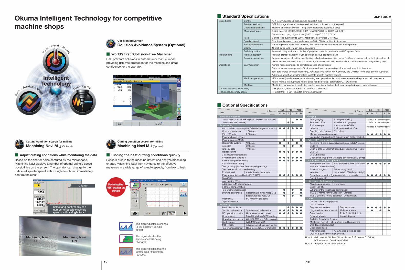
� World’s first “Collision-Free Machine”CAS prevents collisions in automatic or manual mode, providing risk-free protection for the machine and great confidence for the operator.
Okuma Intelligent Technology for competitive machine shops
Ther
mo-Friendly Concept
Col
lis
ion Avoidance System
Machining Navi
IntelligentTechnology
Collision Avoidance System (Optional)Collision prevention
� Finding the best cutting conditions quicklySensors built in to the machine detect and analyze machining chatter. Machining Navi then navigates to the effective measures in a wide range of spindle speeds, from low to high.
Machining Navi M-i (Optional)
Cutting condition search for milling
� Adjust cutting conditions while monitoring the dataBased on the chatter noise captured by the microphone, Machining Navi displays a number of optimal spindle speed possibilities on the screen. The operator can change to the indicated spindle speed with a single touch and immediately confirm the result.
Machining Navi M-g (Optional)
Cutting condition search for milling
Chatter
Select and confirm any of anumber of possible spindlespeeds with a single touch
Machining NaviON
Machining NaviOFF
Machining Navi(OSP) provides the
answer!
This sign indicates a change to the optimum spindle speed.
This sign indicates that spindle speed is being changed.
This sign indicates that the cutting load needs to be reduced.
Basic Specs
Programming
Operations
Communications / Networking
High speed/accuracy specs
Control
Position feedback
Coordinate functions
Min / Max inputs
Feed
Spindle control
Tool compensation
Display
Self-diagnostics
Program capacity
Program operations
Easy Operation
Machine operations
MacMan
X, Y, Z, simultaneous 3 axis, spindle control (1 axis)
OSP full range absolute position feedback (zero point return not required)
Machine coordinate system (1 set), work coordinate system (20 sets)
8-digit decimal, ±99999.999 to 0.001 mm (3937.0078 to 0.0001 in.), 0.001˚
Decimals as: 1 µm, 10 µm, 1 mm (0.0001,1 in.) (1˚, 0.01˚, 0.001˚)
Cutting feed override 0 to 200%, rapid traverse override 0 to 100%
Direct spindle speed commands override 30 to 300%, multi-point indexing
No. of registered tools: Max 999 sets, tool length/radius compensation: 3 sets per tool
15-inch color LCD + touch panel operations
Automatic diagnostics and display of program, operation, machine, and NC system faults
Program storage capacity: 4 GB; operation backup capacity: 2 MB
Program management, editing, multitasking, scheduled program, fixed cycle, G-/M-code macros, arithmetic, logic statements,
math functions, variables, branch commands, coordinate calculate, area calculate, coordinate convert, programming help
“Single-mode operation” to complete a series of operations
Comprehensive management of tool shape and tool compensation information for each tool number
Tool data shared between machining, Advanced One-Touch IGF (Optional), and Collision Avoidance System (Optional)
Advanced operation panel/graphics facilitate smooth machine control
MDI, manual (rapid traverse, manual cutting feed, pulse handle), load meter, operation help, alarm help, sequence
return, manual interrupt/auto return, pulse handle overlap, parameter I/O, PLC monitor
Machining management: machining results, machine utilization, fault data compile & report, external output
USB (2 ports), Ethernet, RS-232-C interface (1 channel)
Hi-G Control, Hi-Cut Pro, pitch error compensation
Standard Specifications
Optional Specifications
OSP-P300M
ItemKit Specs 3D AOT
E
�
�
�
��
�
��
�
�
�
�
�
��
�
���
��
�
�
�
�
�
��
�
���
�
�
�
�
�
�
��
�
���
���
�
�
�
�
�
��
�
���
�
�
�
�
�
�
��
�
���
���
�
D E D E DInteractive functions
Advanced One-Touch IGF-M (Real 3-D simulation included) Interactive Map (I-MAP)
ProgrammingAuto scheduled program update (Scheduled program is standard)Common variables 1,000 sets(Std: 200 sets) 2,000 setsProgram branch; 2 setsProgram notes (MSG)Coordinate system 100 sets selection 200 sets(Std: 20 sets) 400 setsHelical cutting3-D circular interpolationSynchronized Tapping IIArbitrary angle chamferingCylindrical side facingTool grooving (flat-tool free-shaped grooving)Tool max rotational speed settingF1-digit feed 4 sets, 8 sets, parameter Programmable travel limits (G22, G23)Skip (G31)Axis naming (G14)Additional G/M code macros 3-D tool compensationTool wear compensationDrawing conversion Programmable mirror image (G62)
Enlarge/reduce (G50, G51)User task 2 I/O variables (16 each)Tape conversion*
MonitoringReal 3-D simulationSimple load monitor Spindle overload monitorNC operation monitor Hour meter, work counterHour meters Power ON, spindle run/NC ON, machiningOperation end buzzer With M02, M30, and END commandsWork counter With M02 and M30MOP-TOOL Adaptive control, overload monitor Tool life management Hour meter, No. of workpieces
GaugingAuto gauging Touch probe (G31)Auto zero offset Includes auto gaugingTool breakage (touch sensor) (G31)detection Includes auto tool offsetGauging data printout File outputManual gauging (w/o sensor)Interactive gauging (touch-sensor, touch-probe required)
NMLItem
Kit SpecsE
Included in machine specsIncluded in machine specs
Included in machine specs
NML
External I/O communication 2 additional RS-232-C channels (standard specs include 1 channel)DNC-T3DNC-B (232-C, Ethernet transducer used on OSP side)DNC-DTDNC-/Ethernet2 additional USB ports (standard specs include 2 ports)
Automation / untended operation Auto power shut-off M02, END alarms, work preps doneWarm-up (calendar timer) External program Button, rotary switch, selection digital switch, BCD (2-digit, 4-digit)Cycle time reduction (ignores certain commands)Robot, loader I/F
High-speed, high-precisionAbsoScale detection X-Y-Z axesSuper-NURBS0.1 µm control (linear axis commands)TAS-S (Thermo Active Stabilizer––Spindle)TAS-C (Thermo Active Stabilizer––Construction)
Other Control cabinet lamp (inside)Circuit breakerSequence operation Sequence stop Upgraded sequence restart Mid-block returnPulse handle 2 pts, 3 pts (Std: 1 pt)External M code 4-point, 8-pointCollision Avoidance System Machining Navi M-g, M-i (cutting condition search)One-Touch SpreadsheetBlock skip; 3 setsAdditional axes A, B, C axes [preps, specs]OSP-VPS (Virus Protection System)
3D AOT
D E D E D
Note 1. NML: Normal, 3D: Real 3D simulation, E: Economy, D: Deluxe, AOT: Advanced One-Touch IGF-MNote 2. *Requires technical consultation.
� � � � � �
�
�
��
�
�
�
�
�
�
�
�
��
�
�
�
�
�
��
21 22
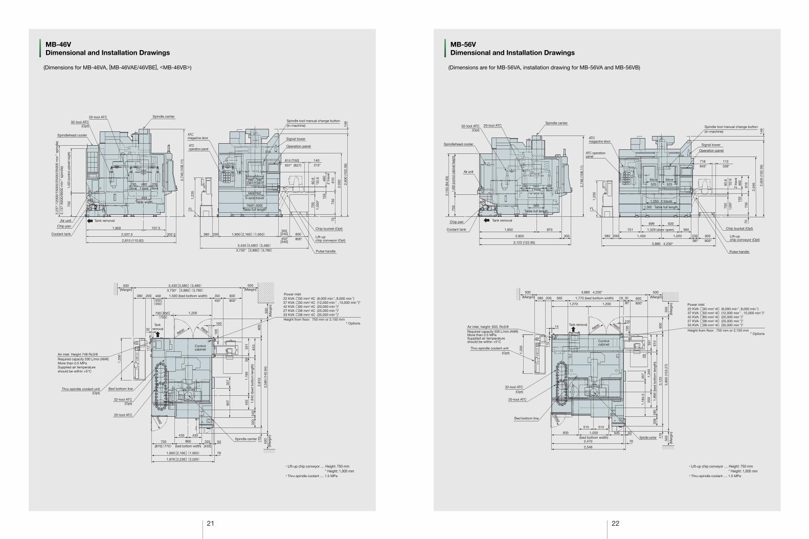
MB-46VDimensional and Installation Drawings
(Dimensions for MB-46VA, [MB-46VAE/46VBE], <MB-46VB>)
MB-56VDimensional and Installation Drawings
(Dimensions are for MB-56VA, installation drawing for MB-56VA and MB-56VB)
2,23
7(12
000/
1500
0/25
000/
3500
0 m
in-1 s
pin
dle
)2,
137(
6000
/800
0 m
in-1 s
pin
dle
)
750
2,74
6 (1
08.1
1)
Air unit
1,800
460Table width
230Move
230Move
2,507.5
2,810 (110.62)
302.5
707.5
Spindlehead cooler
32-tool ATC(Opt)
20-tool ATC Spindle center
Coolant tank
Chip pan
1,40
0 (c
ontro
l cab
inet
hei
ght)
460Y travel
Tank removal
ATC operation panel
ATCmagazine door
1,23
5
FL
70
Chip bucket (Opt)
Lift-upchip conveyor (Opt)
Pulse handle
3,430[3,580]〈3,480〉3,730* [3,880]〈3,780〉�
600 800*
350[240]
450*[340]
200380 1,900[2,160]〈1,950〉�
Spindle tool manual change button (in-machine)
810 [700]
937* [827]140313*
146
2,60
0 (1
02.3
6)
2,00
2610
73015
046
0Z
tra
vel
700
1,00
0*
Signal tower
760[1,000]Table full length
Move280[381]
Move280[381]
560[762]
X-axis travel
60.6
*32.
6
Operation panel
3,430[3,580]〈3,480〉3,730* [3,880]〈3,780〉�
500(Margin)
500(Margin)
20-tool ATC
32-tool ATC(Opt)
Bed bottom lineThru-spindle coolant unit(Opt)
Air inlet Height 748 Rc3/8Required capacity 500 L/min (ANR) More than 0.5 MPaSupplied air temperature should be within +5°C
380 200 400[550]〈450〉�
32
1,500 (bed bottom width)
Tank removal
700[850]〈750〉�
100
100
R600R600
1,33
0
117
1,200
350 450*
600 800*
Controlcabinet
• Lift-up chip conveyor .... Height: 750 mm * Height: 1,000 mm
• Thru-spindle coolant .... 1.5 MPa
Spindle center430
1,900[2,160]〈1,950〉�
1,976[2,236]〈2,026〉�
76
50860(bed bottom width)
720[870]〈770〉�
320[430]
430
170
500
(Mar
gin)
Height from floor: 750 mm or 2,150 mm† Options
Power inlet22 KVA �30 mm2 4C (6,000 min-1, 8,000 min-1)37 KVA �50 mm2 4C (12,000 min-1 , 15,000 min-1)† 42 KVA �60 mm2 4C (20,000 min-1)†
27 KVA �38 mm2 4C (25,000 min-1)†
33 KVA �38 mm2 4C (35,000 min-1)†
500
(Mar
gin)
600
2,81
0
1,64
0 (b
ed b
otto
m le
ngth
)
1,19
045
0
907
R492
357
59
3,58
0 (1
40.9
4)
610
551
240
320
Spindlehead cooler
Chip pan
Air unit
1,950
2,820
3,123 (122.95)
303
870Coolant tank
2,15
0 (8
4.65
)
2,74
6 (1
08.1
1)
1,40
0 (c
ontro
l cab
inet
hei
ght)
750
32-tool ATC(Opt)
20-tool ATCSpindle center
Tank removal
280Move
560Y travel
280Move
Spindle tool manual change button (in-machine)
ATCmagazine door
ATC operationpanel
Signal tower
560
Table full length
Operation panel
Lift-upchip conveyor (Opt)
751
3,880 4,230*
630699
600 800*
70
1,23
5
230 380*
1,450200380
1,329 (door open) 390
FL
Pulse handle
Chip bucket (Opt)
2,60
0 (1
02.3
6)
2,04
5
700
1,00
0*
73015
0
610
Z t
rave
460
60.6
*32.
6
1,020
718 845*
113 336*
1,300 Table full length
1,050 X travel
Move525
Move525
146
Air inlet, height: 933, Rc3/8Required capacity 500 L/min (ANR) More than 0.5 MPaSupplied air temperature should be within +5°C
Thru-spindle coolant unit (Opt)
32-tool ATC(Opt)
20-tool ATC
Bed bottom line
Height from floor: 750 mm or 2,150 mm
22 KVA �30 mm2 4C (6,000 min-1, 8,000 min-1)37 KVA �50 mm2 4C (12,000 min-1 , 15,000 min-1)† 42 KVA �60 mm2 4C (20,000 min-1)†
27 KVA �38 mm2 4C (25,000 min-1)†
33 KVA �38 mm2 4C (35,000 min-1)†
• Lift-up chip conveyor .... Height: 750 mm * Height: 1,000 mm
• Thru-spindle coolant .... 1.5 MPa
500 (Margin)
3,880 4,230*
380 200 565
1,270 1,200
1,770 (bed bottom width) 600 800*
135 230 380*
500 (Margin)
500
(Mar
gin) Power inlet
† Options
1,33
0 110
Tank removalR600
Controlcabinet
R600
100
610
551
100 60
0
14
76
50
2,470
505935
515 515
1,030(bed bottom width)
500
(Mar
gin)
170
Spindle center
2,546
R492
3,12
3
1,89
0 (b
ed b
otto
m le
ngth
)28
5
550
1,18
4.5
357
1,34
0
338
3,89
3 (1
53.2
7)
59
� The sp
ecifications, illustrations, and d
escriptions in this b
rochure vary in different m
arkets and
are subject to change w
ithout notice.P
ub N
o. MB
-V series-E
-(17a)-500 (Mar 2014) P
rinted in Jap
an
When using O
kuma p
roducts, alw
ays read the safety p
recautionsm
entioned in the instruction m
anual and attached
to the prod
uct.
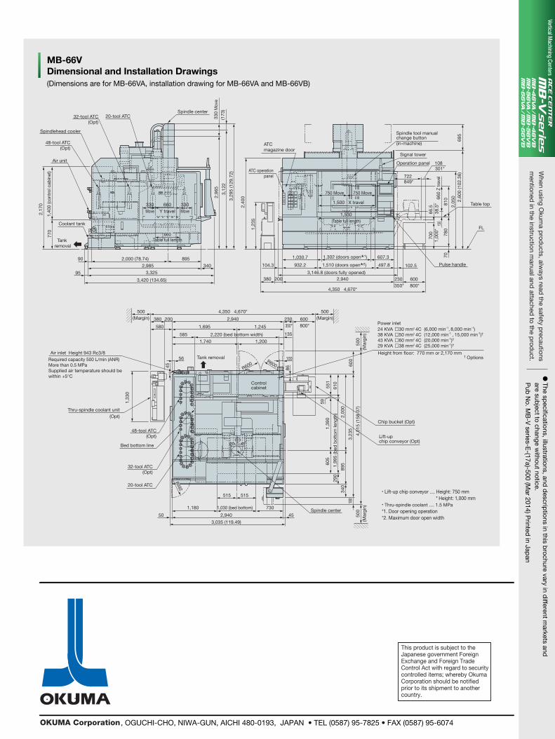
(Dimensions are for MB-66VA, installation drawing for MB-66VA and MB-66VB)
MB-66VDimensional and Installation Drawings
This product is subject to the Japanese government Foreign Exchange and Foreign Trade Control Act with regard to security controlled items; whereby Okuma Corporation should be notified prior to its shipment to another country.
, OGUCHI-CHO, NIWA-GUN, AICHI 480-0193, JAPAN • TEL (0587) 95-7825 • FAX (0587) 95-6074
Vertical Machining Centers
330
Mov
e
Spindlehead cooler
Coolant tank
2,000 (78.74) 895
3402,985
3,325
3,420 (134.65)
3,12
2
2,96
5(1
73)Spindle center
3,29
5 (1
29.7
2)
Air unit
2,17
0
770
1,40
0 (c
ontr
ol c
abin
et)
Tank removal
32-tool ATC(Opt)
48-tool ATC (Opt)
20-tool ATC
660Table full length
330Move
330Move
660Y travel
ATCmagazine door
ATC operationpanel
1,030.7
932.2 1,510 (doors open*2)
2,940
4,350 4,670*
380 200
108301*
2,60
0 (1
02.3
6)69
5
104.3
3,146.8 (doors fully opened)
1,302 (doors open*1)
Signal tower
Spindle tool manualchange button (in-machine)
2,40
0
1,23
5
Operation panel
90
95
722849*
810
2,05
0660
Z tr
avel
750 Move 750 Move
FL
Table top1,500 X travel
497.8 102.5
700
66.5
38.5
*
7078
015
01,
000*
600 800*
230 350*
607.3
1,530(Table full length)
Pulse handle
500
(Mar
gin)
4,01
5 (1
58.0
7)
3,23
5
610
551
59
2,00
0
600
Lift-upchip conveyor (Opt)
Chip bucket (Opt)
Height from floor: 770 mm or 2,170 mm
Power inlet
† Options
24 KVA �30 mm2 4C (6,000 min-1, 8,000 min-1)38 KVA �50 mm2 4C (12,000 min-1 , 15,000 min-1)† 43 KVA �60 mm2 4C (20,000 min-1)†
29 KVA �38 mm2 4C (25,000 min-1)†
45Spindle center
500
(Mar
gin)
180
340
290
1,99
5 (b
ed b
otto
m le
ngth
)
89560
51,
390
• Lift-up chip conveyor .... Height: 750 mm * Height: 1,000 mm
• Thru-spindle coolant .... 1.5 MPa*1. Door opening operation*2. Maximum door open width
Thru-spindle coolant unit(Opt)
48-tool ATC (Opt)
Bed bottom line
32-tool ATC (Opt)
20-tool ATC
50
3,035 (119.49)
2,940
1,180
515 515
730
1,33
0
1,030 (bed bottom)
R492
Required capacity 500 L/min (ANR) More than 0.5 MPaSupplied air temperature should be within +5°C
Air inlet Height 943 Rc3/8
500(Margin)
4,350 4,670*
2,940380
580
585
1,740 1,200
2,220 (bed bottom width)
200
1,695 1,245
Controlcabinet
500(Margin)
56 100
R600R600
230 350*
135
600 800*
86
Tank removal
45


