1299 Orleans Drive, Sunnyvale CA 94089 T 408 543 1500 F 408 543 1501 www.bloomenergy.com 05/06/2021 Melanie Bachman Connecticut Siting Council Ten Franklin Square, New Britain, CT 06051 RE: PETITION NO. 1387, Bloom Energy Corporation petition for a declaratory ruling, pursuant to Connecticut General Statutes § 4-176 and § 16-50k, for the proposed construction, maintenance, and operation of a grid-side 10-megawatt (MW) fuel cell facility and associated equipment to be located at Eversource Energy’s existing Judd Brook electrical distribution substation, 160 Old Amston Road, Colchester, Connecticut Dear Ms. Bachman, At a public meeting held on January 2, 2020, the Connecticut Siting Council (Council) considered and ruled that the above-referenced proposal would not have a substantial adverse environmental effect, and pursuant to Connecticut General Statutes § 16-50k would not require a Certificate of Environmental Compatibility and Public Need with certain conditions. As requested in the declaratory ruling, the following information is being provided not less than 15 days prior to any fuel pipe cleaning operations related to the fuel cell construction, installation, or modification. 5. The use of natural gas as a fuel system cleaning medium during fuel cell construction, installation or modification shall be prohibited; Bloom Energy uses an inert gas (Nitrogen) to handle cleaning the fuel system during construction, installation, or modification of its fuel cell projects. 6. Submit the following information to the Council 15 days prior to any fuel pipe cleaning operations related to fuel cell construction, installation, or modification: Pipe cleaining operations occur during the commissioning stage of the project. A copy of the “Gas System Commissioning” standard operating procedure (SOP) is provided as Exhibit 1. The information below derives from this SOP. a. Identification of the cleaning media to be used; Nitrogen is the cleaning media to be used. b. Identification of any known hazards through use of the selected cleaning media; Nitrogen is selected as a cleaning media as it is inherently safe, however there are hazards in dealing with any high pressure gas including, operating the equipment, debris existing in the lines during the cleaning process, high noise, and typical construction site hazards.
Transcript
1299 Orleans Drive, Sunnyvale CA 94089 T 408 543 1500 F 408 543 1501 www.bloomenergy.com
05/06/2021
Melanie Bachman Connecticut Siting Council Ten Franklin Square, New Britain, CT 06051
RE: PETITION NO. 1387, Bloom Energy Corporation petition for a declaratory ruling, pursuant to Connecticut General Statutes § 4-176 and § 16-50k, for the proposed construction, maintenance, and operation of a grid-side 10-megawatt (MW) fuel cell facility and associated equipment to be located at Eversource Energy’s existing Judd Brook electrical distribution substation, 160 Old Amston Road, Colchester, Connecticut
Dear Ms. Bachman,
At a public meeting held on January 2, 2020, the Connecticut Siting Council (Council) considered and ruled that the above-referenced proposal would not have a substantial adverse environmental effect, and pursuant to Connecticut General Statutes § 16-50k would not require a Certificate of Environmental Compatibility and Public Need with certain conditions. As requested in the declaratory ruling, the following information is being provided not less than 15 days prior to any fuel pipe cleaning operations related to the fuel cell construction, installation, or modification.
5. The use of natural gas as a fuel system cleaning medium during fuel cell construction,installation or modification shall be prohibited;
Bloom Energy uses an inert gas (Nitrogen) to handle cleaning the fuel system duringconstruction, installation, or modification of its fuel cell projects.
6. Submit the following information to the Council 15 days prior to any fuel pipe cleaningoperations related to fuel cell construction, installation, or modification:
Pipe cleaining operations occur during the commissioning stage of the project. A copy of the“Gas System Commissioning” standard operating procedure (SOP) is provided as Exhibit 1.The information below derives from this SOP.
a. Identification of the cleaning media to be used;
Nitrogen is the cleaning media to be used.
b. Identification of any known hazards through use of the selected cleaning media;
Nitrogen is selected as a cleaning media as it is inherently safe, however there arehazards in dealing with any high pressure gas including, operating the equipment, debrisexisting in the lines during the cleaning process, high noise, and typical construction sitehazards.
1299 Orleans Drive, Sunnyvale CA 94089 T 408 543 1500 F 408 543 1501 www.bloomenergy.com
c. Description of how known hazards will be mitigated, including identification ofany applicable state or federal regulations concerning hazard mitigationmeasures for such media;
Bloom Energy and its contractors will proceed in accordance to the provided method ofprocedure in addition to compliance with OSHA and NFPA standards. CompressedNitrogen will be transported and handled in compliance with all federal, state, and localcodes, PPE will be worn at all times, and areas of hazard will be barricaded off.
d. Identification and description of accepted industry practices or relevantregulations concerning the proper use of such media;
OSHA, NFPA 54, NPFA 56, NFPA 853, ASME B31 and DOT Title 49
e. Provide detailed specifications (narratives/ drawings) indicating the locationand procedures to be used during the pipe cleaning process, including anynecessary worker safety exclusion zones;
Ensure all PPE is in place
o Min requirements: Safety glasses, gloves, hardhat, high visibilityclothing, safety shoes, hearing protection, combustible gas monitor,and oxygen monitor.
Set up barricades around all above ground points of the fuel line to becleaned and ensure all non-essential personal removed. Areas to bebarricaded and where cleaning to take place shown on the below fuel pipingschematic.
Ensure all fuel system valves closed and isolate the incoming utility gasvalve and the fuel cell gas meter.
Connect Nitrogen gas bottle through a regulator downstream of theincoming gas utility valve at the fuel cell gas meter.
Connect vent hoses at the fuel cell gas connections and open valves asrequired to allow flow from the Nitrogen gas bottle through the fuel systemplumbing to clean out system of moisture and residual debris.
1299 Orleans Drive, Sunnyvale CA 94089 T 408 543 1500 F 408 543 1501 www.bloomenergy.com
o Monitor combustible gas levels and oxygen levels on all personalduring cleaning process. Closes valves and halt the cleaningprocess and notify the process supervisor if the combustible gaslevels exceed 25% of LEL (Lower Explosive Limit) or if the oxygenlevels fall below 19.5%.
Remove vent hoses from the fuel cell gas connection and close the valvesat the fuel cell connections.
Remove the Nitrogen gas bottle and regulator from the fuel cell gas meter.
f. Identification of the contractor or personnel performing the work, including adescription of past project experience and the level of training and qualificationsnecessary for performance of the work;
Employees of Bloom Energy will oversee and perform the procedures detailed in theGas System Commissioning procedure. Bloom Energy has safely commissioned morethan 140 fuel cell installation projects in California, New York, New Jersey, Delawareand Connecticut. The required safety trainings to complete this procedure include:
Natural Gas Safety Compressed Nitrogen Safety Fire Extinguisher Safety Combustible Gas Indicator Operation Corporate Control of Hazardous Energies
g. Contact information for a special inspector hired by the project developer who isa Connecticut Registered Engineer with specific knowledge and experienceregarding electric generating facilities or a National Board of Boiler and PressureVessel Inspector and written approval of such special inspector by the local firemarshal and building inspector; and
Robert M. Andel, PE Complete Connections, LLC Mechanical Engineer CT License #10744 203-500-1743 (mobile)
A company profile of Complete Connections, LLC is provided as Exhibit 2, and demonstrates specific knowledge and experience regarding generating facilities.
h. Certification of notice regarding pipe cleaning operations to all state agencieslisted in General Statutes § 16-50j(h) and to the Department of ConsumerProtection, Department of Labor, Department of Public Safety, Department ofPublic Works, and the Department of Emergency Management and HomelandSecurity.
Bloom Energy has provided notice via Certified Mail (Exhibit 3) to the followingagencies:
Department of Energy and Environmental Protection Department of Public Utility Regulatory Authority
1299 Orleans Drive, Sunnyvale CA 94089 T 408 543 1500 F 408 543 1501 www.bloomenergy.com
Department of Public Health Protection Council on Environmental Quality Department of Agriculture Office of Policy and Management Department of Transportation Department of Economic and Community Development Division of Emergency Management and Homeland Security (DEMHS) Department of Consumer Protection Department of Administrative Services Department of Labor
1299 Orleans Drive, Sunnyvale CA 94089 T 408 543 1500 F 408 543 1501 www.bloomenergy.com
Exhibit 1
Gas System CommissioningSS-OP-013 Estimated Evolution Time: 2 hrs Revision: A Number of Personnel: 2 Effective Date: xx/xx/xx
Company Confidential 1 of 6
Always refer to SS-OP-017-F-01 for most recent version. When printed or copied, document is for reference only as of 3/1/2017
PURPOSE: 1) This procedure is intended to provide a clear process for CIG field workers to safely ensure natural gas is being
delivered to site within Bloom Energy Specifications. More specifically, the objective of this procedure is to:a. Ensure Compliance with:
i. NFPA 54 National Fuel Gas Codeii. OSHA and Cal OSHA construction safety standardsiii. Title 49 of the Code of Federal Regulations (DOT) safety standardsiv. Regional Air Quality Management Board Regulationsv. Bloom Energy’s Critical to Quality Standards, especially regarding
1. Gas piping system blow-down and purging standards2. Gas moisture content verification
SCOPE: 1) This procedure applies to all workers involved in the commissioning of gas piping systems on customer installation
sites.
REQUIRED SAFETY TRAININGS: 1) Natural Gas Safety2) Compressed Nitrogen Safety3) Fire Extinguisher Safety4) Combustible Gas Indicator Operation5) Corporate Control of Hazardous Energies
REQUIRED PPE: 1) Safety Glasses2) Gloves3) Hard Hat4) High Visibility Clothing5) Work boots with safety toe
SPECIAL PRECAUTIONS & POTENTIAL HAZARDS: 1) Verify gas piping system has been pressure tested for leaks by the utility and general contractor before executing this
SOP.2) Never make any physical manipulation of gas piping systems (excluding operating listed valves) without first isolating
the equipment on which to be worked and safely bleeding pressure.a. This procedure involves controlling stored, pneumatic, and thermal energy. Refer to the Corporate Control of
Hazardous Energy Standard to ensure proper Lock Out/Tag Out (LOTO) procedures are followed.b. To bleed line pressure when opening valves on isolated piping segments, slowly turn the valve ¼ of the way
towards the “ON” or open position before fully opening the valve.3) Compressed gas must be handled and transported in accordance with all applicable federal, state, local, and
corporate standards, including BE policy and DOT regulations.4) Nitrogen and natural gas may displace oxygen and cause rapid suffocation. Oxygen monitoring is required before
entering any confined space containing stored nitrogen and as otherwise directed in this SOP.
REQUIRED TECHNICAL QUALIFICATIONS: 1) Each involved worker must be documented as a BE Qualified Gas System Person
a. Required training includes Gas Regulator Fundamentals, in addition to all of this SOP’s required safetytrainings
Gas System CommissioningSS-OP-013 Estimated Evolution Time: 2 hrs Revision: A Number of Personnel: 2 Effective Date: xx/xx/xx
Company Confidential 2 of 6
Always refer to SS-OP-017-F-01 for most recent version. When printed or copied, document is for reference only as of 3/1/2017
REQUIRED TOOLS, MATERIALS, & EQUIPMENT: 1) Bloom Energy FPM Gas Bypass Hose2) (2) Multi-Gas Monitor : minimum detection of Oxygen and Methane LEL
a. Recommended: Industrial Scientific MX43) NFPA 54 Compliant Combustible Gas Indicator
a. Recommended: Sensit G24) Adjustable Wrench Set and/or two (2) pipe wrenches5) Gas Sampling Kit- BE PN 1253626) Filled Nitrogen Tank
a. QTY 1 size Q tank per 250 linear feet of 2” gas line (Praxair part NI-Q) orb. QTY 1 size S tank per 500 linear feet of 2” gas line (Praxair part NI-S)
7) Nitrogen Purge Kit (per CIG Tooling List)8) Caution tape and delineators9) Fire Extinguisher (2A or better)
SUPPORTING DOCUMENTS: 1) NFPA 542) DOC-1004338 Install CTQ (Critical to Quality)3) SS-OP-032-F-01_Site Verification Checklist_RevA4) CAT-FPM-1018 Rae Tube Gas Sampling5) SS-RD-001_CIG Tooling_Rev00
RESPONSIBILITIES: 1) One (1) Process Supervisor2) One (1) Discharge Attendant
PROCEDURE: 1) Don PPE.2) Turn on combustible gas/oxygen monitors and attach one to each person performing the work.3) Set up cones and caution tape to establish a discharge area around the FPM farthest from the MSA with a 10 foot
radius around the point of discharge. Remove all non-essential personnel.4) Ensure a 2A or better fire extinguisher is located within 50 feet of the discharge area.5) Locate the valve(s) on the gas line stub-up(s) inside the Fuel Processing Module(s) (FPM). They are labelled “12” in
SI2.1 of the Standard Drawing Set.a. Ensure each stub-up valve is in the “OFF” position. If it is not in the “OFF” position, slowly turn the valve until
it is off.
Gas System Commissioning
SS-OP-013 Estimated Evolution Time: 2 hrs Revision: A Number of Personnel: 2 Effective Date: xx/xx/xx
Company Confidential 3 of 6
Always refer to SS-OP-017-F-01 for most recent version. When printed or copied, document is for reference only as of 3/1/2017
6) Locate the Isolation Valve on the houseline riser at the utility gas Meter Set Assembly (MSA). It is labelled “15” in
SI2.1 of the Standard Drawing Set. a. Ensure the valve is in the “OFF” position. If it is not in the “OFF” position, slowly turn the valve to close it in
the “OFF” position.
7) Apply Lock out and Tag out devices to valve 15 per Bloom Energy’s Control of Hazardous Energies Standard. 8) Follow the gas line from the MSA riser all the way to the FPM(s) and ensure all except the stub-up valves are open or
“ON.” a. Again ensure the stub-up valves are closed “OFF.”
9) Position Discharge Attendant with air monitor at the point of discharge. 10) Connect the FPM Bypass Hose to the gas stub-up and the discharge hose in the FPM furthest from the MSA.
a. Valve/strainer integral to the bypass hose should be connected on the discharge side of the hose. Ensure valve is in the “OFF” position. Ensure strainer is positioned down.
11) Ensure 10 ft. clearance from point of discharge to building openings and ignition sources. 12) Ensure 25 ft. clearance from point of discharge to mechanical building air intakes. 13) Position the nitrogen tank near the houseline riser on the MSA in accordance with Bloom Energy’s compressed gas
safety policies. 14) With the nitrogen tank valve confirmed “OFF,” install the approved regulator to the nitrogen tank. 15) Turn the nitrogen tank regulator pressure control valve in the direction that decreases pressure as far as possible to
prevent any gas flow through the regulator 16) Connect nitrogen purge hose to the regulator output. 17) Locate the ¼” test valve located just downstream of the houseline riser isolation valve.
Gas System CommissioningSS-OP-013 Estimated Evolution Time: 2 hrs Revision: A Number of Personnel: 2 Effective Date: xx/xx/xx
Company Confidential 4 of 6
Always refer to SS-OP-017-F-01 for most recent version. When printed or copied, document is for reference only as of 3/1/2017
a. Verify the test valve is in the “OFF” position. If it is not in the “OFF” position, slowly turn the valve to close it inthe “OFF” position.
18) Remove any caps, pressure gauges, or other fittings that may be installed on the downstream side of the ¼” testvalve.
19) Connect the nitrogen purge hose to the ¼” test valve.a. Be sure to tape threads on fittings to prevent leaks
20) Slowly open the nitrogen tank valve.21) Slowly turn the nitrogen tank regulator pressure control valve in the direction that increases pressure until the output
reaches 60 PSI.a. If any leaks are detected between the nitrogen tank and the MSA, close the nitrogen tank valve, decrease the
pressure control valve all the way, let pressure bleed out, then remove and re-tape fittings as necessary tocorrect the leak. Follow steps 18-20 again once the leak is corrected.
22) Communicate to the Discharge Attendant to slowly open the stub up valve (12) and FPM bypass hose valve at thefurthest FPM to bleed pressure from the entire private side of the MSA.
23) Within a few seconds after the FPM bypass hose valve is opened, open the ¼” test valve on the MSA to introducenitrogen to the piping system.
24) Discharge attendant shall continuously monitor the discharge area and be prepared to close the FPM bypass hosevalve.
a. If combustible gas levels exceed 25% of LEL (Lower Explosive Limit) in the discharge area, close the valve,evacuate the discharge area, and notify the process supervisor to close the 1’4” test valve at the MSA.
b. If oxygen levels fall below 19.5%, stop purging, evacuate the discharge area, and notify the processsupervisor to close the ¼” test valve at the MSA.
25) Let nitrogen flow through the piping system with FPM Bypass hose valve open for 30 seconds.26) Close the FPM bypass hose valve.
STEPS 27-37 RELATE TO SETTING PRIVATE REGULATORS. MOVE ON TO STEP 38 IF RECEIVING FIXEDPRESSURE FROM THE UTILITY.
27) Continue to inject nitrogen into the piping system until the pressure gauge on the upstream Regulator Set Assembly(RSA) riser reads 50 psi.
28) Once the pressure gauge on the upstream riser of the RSA reads 50 psi, close the ¼” test valve at the MSA to stopinjecting nitrogen.
29) Locate the closing caps on the spring case of the regulators in the RSA and remove them.a. There may be several closing caps to remove, both on the working regulator(s) and pilot regulator(s)
30) Tighten the loading spring adjustment screw to increase outlet pressure on the downstream working regulator anddownstream pilot regulator, if applicable.
Gas System Commissioning
SS-OP-013 Estimated Evolution Time: 2 hrs Revision: A Number of Personnel: 2 Effective Date: xx/xx/xx
Company Confidential 5 of 6
Always refer to SS-OP-017-F-01 for most recent version. When printed or copied, document is for reference only as of 3/1/2017
a. Initially, outlet pressure on both of these regulators should be greater than 25 psi. Estimate how much to tighten the adjustment screw to achieve this.
31) Slowly turn the FPM bypass hose valve at the point of discharge to allow just enough pressure to bleed to create flow through the regulators.
32) Using the pilot regulator gauge to measure pressure, adjust the upstream pilot regulator, if applicable, to 21 psi a. Use the gauges installed on the downstream RSA riser if pilot does not have integrated gauge.
33) Using the gauge installed on the downstream RSA riser to measure pressure, adjust the upstream working monitor regulator to 18 psi.
34) Using the pilot gauge or the downstream RSA riser gauge to measure pressure, set the downstream pilot regulator to 18 psi.
a. Since the upstream working monitor regulator is also set to 18, loosen the downstream pilot adjustment screw to allow the pressure to fall below 18, then tighten until the needle on the gauge stops increasing.
35) Using the gauge installed on the downstream RSA riser to measure pressure, adjust the downstream working regulator to 15 psi.
36) If, during steps 30-34, the pressure on the upstream RSA riser gauge drops below 25 psi, STOP, and re-pressurize the line to 50 psi by closing the FPM bypass hose valve and opening the MSA ¼” test valve.
37) Close the FPM bypass hose valve. 38) Open the ¼” test valve at the MSA to inject nitrogen until the pressure gauge on the upstream riser of the Regulator
Set Assembly (RSA) reads 50 psi. 39) Close the ¼” test valve at the MSA to stop injecting nitrogen into the piping system. 40) Quickly open the valve on the FPM bypass hose valve to release the pressure in the line and blow out the piping
system at the FPM furthest from the MSA. 41) Once the pressure is released, close the stub up valve (12). 42) Disconnect the FPM bypass hose and connect it at the next closest FPM at the site, similar to step 5. 43) Set up cones and caution tape to establish a discharge area around the next closest FPM with a 10 foot radius around
the point of discharge. Remove all non-essential personnel. 44) Ensure 10 ft. clearance from point of discharge to building openings and ignition sources. 45) Ensure 25 ft. clearance from point of discharge to mechanical building air intakes. 46) Repeat steps 38 through 43 for each additional Energy Server on site. 47) Communicate to all persons present that LOTO devices will be removed and the gas piping system will be energized. 48) Remove the LOTO devices from the locked out isolation valve at the MSA. 49) Slowly open the isolation valve on the houseline riser at the MSA. 50) Set up cones and caution tape to establish a discharge area around the FPM farthest from the MSA with a 10 foot
radius around the point of discharge. Remove all non-essential personnel. 51) Re-position discharge attendant with NFPA 54 compliant combustible gas indicator (CGI) at point of discharge. 52) Continuously monitor:
a. within the pipe at the point of discharge with NFPA 54 compliant CGI for combustible gas % by volume b. the discharge area oxygen % by volume c. the discharge area Combustible Gas % of LEL
53) Slowly open the FPM bypass hose valve to begin purging nitrogen from the system. 54) Verify pressure at the RSA outlet riser is 15 psi. 55) Purging shall stop when 90% combustible gas by volume is detected in the line at the point of discharge.
a. If oxygen levels fall below 19.5% by volume in the discharge area, stop the purge and relocate all personnel to a safe area. Allow the gases that are displacing oxygen to dissipate before continuously monitoring oxygen levels while approaching the point of discharge to resume purging.
b. If combustible gas exceeds 25% of LEL in the discharge area, stop the purge and relocate all personnel to a safe area. Allow the gases to dissipate before continuously monitoring % of LEL while approaching the point of discharge to resume purging.
56) Complete CAT-FPM-1018 Rae Tube Gas Sampling at FPM furthest from MSA.
Gas System CommissioningSS-OP-013 Estimated Evolution Time: 2 hrs Revision: A Number of Personnel: 2 Effective Date: xx/xx/xx
Company Confidential 6 of 6
Always refer to SS-OP-017-F-01 for most recent version. When printed or copied, document is for reference only as of 3/1/2017
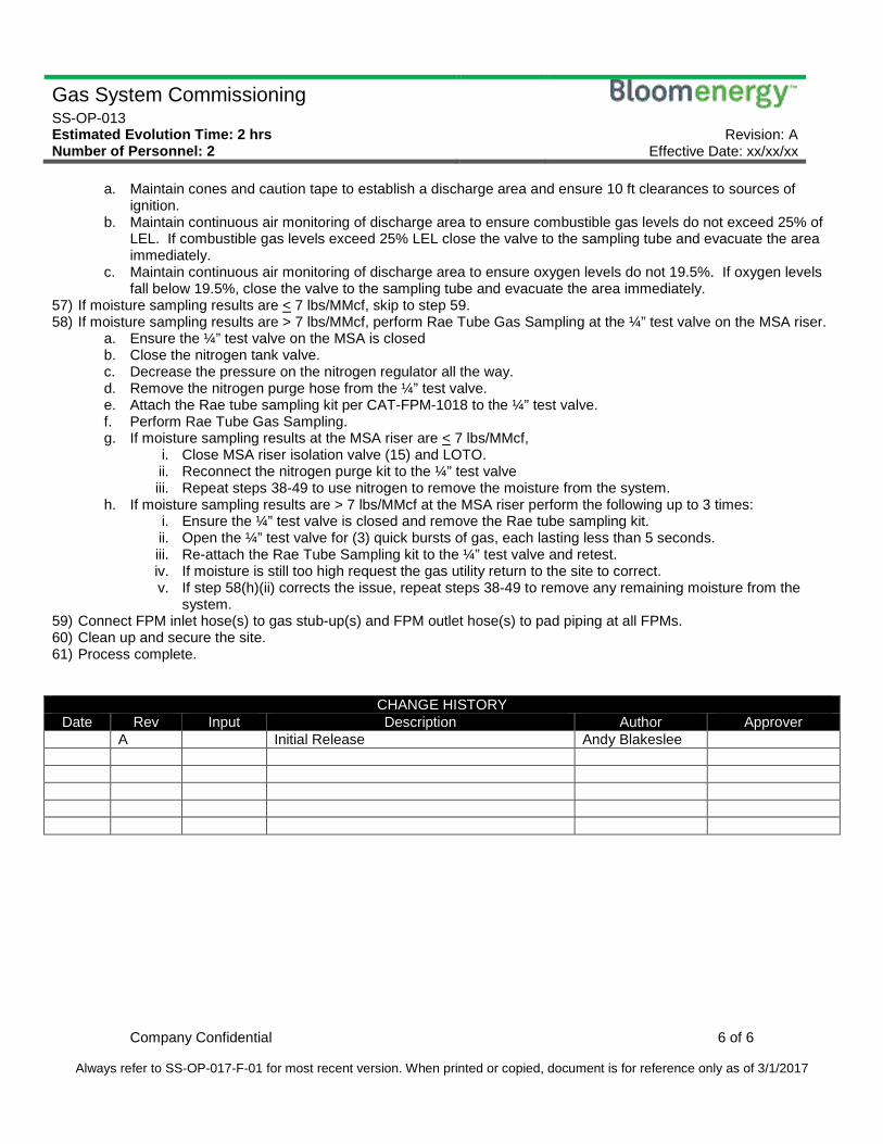
a. Maintain cones and caution tape to establish a discharge area and ensure 10 ft clearances to sources ofignition.
b. Maintain continuous air monitoring of discharge area to ensure combustible gas levels do not exceed 25% ofLEL. If combustible gas levels exceed 25% LEL close the valve to the sampling tube and evacuate the areaimmediately.
c. Maintain continuous air monitoring of discharge area to ensure oxygen levels do not 19.5%. If oxygen levelsfall below 19.5%, close the valve to the sampling tube and evacuate the area immediately.
57) If moisture sampling results are < 7 lbs/MMcf, skip to step 59.58) If moisture sampling results are > 7 lbs/MMcf, perform Rae Tube Gas Sampling at the ¼” test valve on the MSA riser.
a. Ensure the ¼” test valve on the MSA is closedb. Close the nitrogen tank valve.c. Decrease the pressure on the nitrogen regulator all the way.d. Remove the nitrogen purge hose from the ¼” test valve.e. Attach the Rae tube sampling kit per CAT-FPM-1018 to the ¼” test valve.f. Perform Rae Tube Gas Sampling.g. If moisture sampling results at the MSA riser are < 7 lbs/MMcf,
i. Close MSA riser isolation valve (15) and LOTO.ii. Reconnect the nitrogen purge kit to the ¼” test valveiii. Repeat steps 38-49 to use nitrogen to remove the moisture from the system.
h. If moisture sampling results are > 7 lbs/MMcf at the MSA riser perform the following up to 3 times:i. Ensure the ¼” test valve is closed and remove the Rae tube sampling kit.ii. Open the ¼” test valve for (3) quick bursts of gas, each lasting less than 5 seconds.iii. Re-attach the Rae Tube Sampling kit to the ¼” test valve and retest.iv. If moisture is still too high request the gas utility return to the site to correct.v. If step 58(h)(ii) corrects the issue, repeat steps 38-49 to remove any remaining moisture from the
system.59) Connect FPM inlet hose(s) to gas stub-up(s) and FPM outlet hose(s) to pad piping at all FPMs.60) Clean up and secure the site.61) Process complete.
CHANGE HISTORY Date Rev Input Description Author Approver
A Initial Release Andy Blakeslee
1299 Orleans Drive, Sunnyvale CA 94089 T 408 543 1500 F 408 543 1501 www.bloomenergy.com
Exhibit 2
Complete Connection, LLC 326 West Main Street, Milford, CT 06460
Consulting Engineers 203-878-4065
1
Company Profile
Complete Connection, LLC, established in December 2002, is an electrical and mechanicalconsulting engineering firm having over 195 years combined experience in facilities and electricpower system design, operation and maintenance. Robert Kish, Principal Engineer and Owner,has a B.S. in Electrical Engineering and is a registered professional engineer in the State ofConnecticut. His technical staff includes three senior mechanical engineers and one electricalengineer. Special credentials include P.E. licenses in CT, NY and NJ, Business EnergyProfessional (BEP), Certified Energy Manager (CEM) and Building Energy Assessment
Professional (Ashrae BEAP). Personnel have extensive work experience in the power generation,electric utility and facilities industries, primarily in project management, engineering, operationsand maintenance. Power facility types have included large coal-, oil-, and gas-fired conventionalsteam, as well as gas- and oil-fired combined cycle and simple cycle plants. Significant workhas also been done on behalf of large aerospace, other industrial, and institutional entities.
Complete Connection, LLC specializes in three areas: 1.) providing consulting services to powerplant executives, management, and their associates regarding plant asset evaluation andimprovements, risk mitigation, and margin enhancement; 2.) providing engineering and fieldsupport services directly to utility, generation and industrial clients who may not have thetechnical resources on staff to meet the demands of their workload; and 3.) providing short-termservices to engineering firms needing assistance during peak work periods, relieving them of theneed to hire permanent full-time personnel.
Complete Connection, LLC assignments are primarily “brownfield” projects involving energyproduction, utilization and conservation, environmental compliance, safety, modernizationand/or process improvement. Its engineers utilize extensive experience in construction,maintenance and operations as well as troubleshooting and diagnostics of plant systems todevelop their own designs and/or evaluate designs proposed by other engineers or vendors. Theymanage projects through all phases, direct startups and create documents and procedures.
Industry Skills, Experience and Capabilities
Management Consulting - Generating Plants and Industrial Facility Experience.
Plant/Asset Management - Assist with developing detailed O&M budgets, capital-spendingand long-term plans, comprehensive asset evaluation and management plans. Providetechnical support to negotiation of long term service agreements for F-class or similarcombustion turbines. Perform due diligence in support of large-asset sales. Interface withpower marketing entities.
Effective Cause Analysis – Using proven methods to explore in depth the physical, cultural,operational, and other causes of events of any scale and in any program area as a foundationto develop comprehensive corrective actions that will truly mitigate risk.
Complete Connection, LLC 326 West Main Street, Milford, CT 06460
Consulting Engineers (203)-878-4065
2
Emergency Response Preparedness – Tailor proven and effective written checklist-style andother short-form guidance to be used under a broad range of emergent circumstances toensure that potentially high-consequence incidents do not occur or have minimal impact ifthey do.
Excellence In Routine O&M – Develop and/or refine operating procedures that enhance userunderstanding while reducing risk of error.
Risk Assessment – Apply experience with real-world events to facilitate assessments of thephysical facility, O&M programs, and other vulnerabilities to identify precursorcircumstances increasing risk of a significant incident.
NERC Reliability Program Evaluation – Ensure quality procedures and documentation are inplace so that compliant RSAW’s may be developed for each applicable standard.
Due Diligence Support – Utilize significant plant-side due diligence experience to understandwhat are the questions that really should be asked, and how to develop an accurate picturefrom incomplete information.
Margin Enhancement by Availability and Reliability Improvement - Combine robust causeanalysis with sound engineering to solve the chronic and one-off problems that affect aplant’s ability to meet dispatch. Engineering services are available for systems reviews,upgrades, or wholesale replacements.
Margin Enhancement by Startup, Variable, and No-Load Cost Analyses – Help theowner/operator to understand how to quantify and classify all of the costs that should beincluded in a dispatch model.
Margin Enhancement by Capability Opportunity Assessment – Provide support to theprocess of identifying and evaluating potential facility changes that can generate additionalmargin.
Margin Enhancement by Cycle Efficiency Assessment and Improvement – Utilize a strongbackground in thermodynamics to help the owner/operator understand where heat-rateimprovements are available and which can be addressed cost effectively.
Owner’s Engineer – Identify problems and investigate causes, provide conceptual designs atthe inception of a project; ensure client’s goals are met by clarifying project functionalrequirements; evaluate drawings, specifications and technical proposals by other engineersand vendors; Review and interpret codes; manage projects; prepare project justifications, costestimates and schedules; supervise technical personnel.
Client’s On-Site Engineer - Verify contract compliance; conduct field inspections; answerRFI’s, liaise between constructor and firm’s engineering office; report irregularities; witnessstartup testing; provide startup records control.
Third Party Audits - Perform field audits to verify contractor performance; attend factoryacceptance tests (FAT’s) on behalf of the client; verify accuracy of demand-reduction valuesreported to ISO; verify contractor applications for energy rebates.
Complete Connection, LLC 326 West Main Street, Milford, CT 06460
Consulting Engineers (203)-878-4065
3
Document Management - Create as-built documentation, especially involving integration ofnew construction with existing equipment and systems; edit existing customer drawings; scanand catalog documentation; work seamlessly with owner/operator EDMS systems andtechnical libraries.
O&M Support - Troubleshoot plant problems and propose solutions; analyze process datausing DCS or PI; perform formal root cause failure analysis; write startup/ test /operatingprocedures; perform maintenance planning; provide CMMS support and procedure writing.
Compliance Program Support – Assist with ensuring compliance to standards andrequirements of NERC; OSHA; NFPA Codes and Standards, NFPA 70E; Classify hazardousareas; Write stormwater pollution prevention plans and spill prevention procedures; Assistwith Title V, NPDES, and pretreatment permit applications, monitoring, testing, andreporting.
Power Generation Electrical Engineering Services: Research and choose components forapplication in power generation plants; e.g. cable tray fire repairs; assist with implementationof insurance company recommendations; write contingency plans, support plant DCSupgrades, turbine control and generator excitation system upgrades; write specifications forequipment procurement; supervise equipment start-up and system commissioning.
Electrical Power Systems Design: Provide layout, design, sizing and selection of electricalequipment including medium and low voltage switchgear, motors, generators, transformers,panel boards, lighting, MCC’s, VFD’s, UPS, batteries, chargers, inverters, duct lines, cabletray, grounding, wire, cable. Develop designs to suit client’s reliability objectives, writespecifications for equipment procurement.
Due-diligence Electrical System Investigations: Perform facility inspections to determineexisting conditions, uncover problems and electrical system deficiencies; perform codecompliance review and make recommendations for improvements; create as-built drawingsto facilitate next-phase project design.
Construction Document Review: Provide an independent review of electrical constructiondocuments before they are issued to uncover design deficiencies; verify code compliance;ensure coordination with other disciplines and identify constructability issues.
Emergency/ Standby Systems. Perform generator sizing studies; determine application andselection of engine-generators and accessory equipment including batteries, chargers,grounding devices, synchronizing control panels, transfer switches, stacks, mufflers, noiseabatement, cooling, and fuel supplies; address NFPA code compliance, air emissions andpermits.
Complete Connection, LLC 326 West Main Street, Milford, CT 06460
Consulting Engineers (203)-878-4065
4
Power Systems Studies. Perform modeling of power system using SKM System Analysis,Inc. software for fault current, voltage drop, motor starting, power factor, arc flash anddevice coordination.
Relay Protection and Control. Develop one lines, three lines, P&ID’s and logic diagrams;Determine proper application and selection of protective relays, metering, SCADA and DCSequipment; Prepare specifications, detailed connection diagrams, and relay settings.
Licensed Mechanical Design Engineer - Generating Plant and Facilities Experience.
Power Generation Mechanical Engineering Services: Research and choose components forapplication in power generation plants; e.g., piping, control, safety and relief valves, pressurevessels and tanks, pumps, fans, compressors, and controls; design pump and piping systemsin compliance with ASME B31.1 Power Piping Code, including pipe sizing, pump selection,pipe expansion calculations, pipe hanger design, material and insulation selection; writespecifications for equipment procurement; supervise equipment start-up and systemcommissioning.
HVAC System Design and Analysis: Model new and existing buildings using loadcalculation and energy estimating software in order to determine peak heating and coolingloads and energy usage. Provide the layout and design of air ducts and chilled water, hotwater, and steam piping; sizing and selection of mechanical equipment, including airhandlers, chillers, boilers, cooling towers, pumps, fans, fan coils, packaged unitary andterminal equipment; develop control system functional designs; lay out, design and specifymechanical room and central heating/cooling plants.
Due-diligence System Investigations: Perform facility inspections to determine existingconditions; uncover problems and system deficiencies; assess code compliance; and makerecommendations for improvements.
Energy Audits: Perform facility inspections to uncover inefficient use of electrical andthermal energy; determine opportunities to reduce energy consumption; ascertain thecondition of mechanical and electrical equipment; and make recommendations to lowerutility bills.
Construction Document Review: Provide an independent review of mechanical constructiondocuments before they are issued to uncover design deficiencies; verify code compliance;ensure coordination with other disciplines and identify constructability issues.
Troubleshooting System Operating Problems: Analyze the operation of systems andcomponents using instrumentation already installed in a client’s facility; review systemdesign drawings and compare design intent to installed conditions; identify possible causesfor system or component operating problems; make recommendations for further testing andfor corrective actions.
1299 Orleans Drive, Sunnyvale CA 94089 T 408 543 1500 F 408 543 1501 www.bloomenergy.com
Exhibit 3
VIA ELECTRONIC MAIL
05/06/2017
RE: PETITION NO. 1387, Bloom Energy Corporation petition for a declaratory ruling, pursuant to Connecticut General Statutes § 4-176 and § 16-50k, for the proposed construction, maintenance, and operation of a grid-side 10-megawatt (MW) fuel cell facility and associated equipment to be located at Eversource Energy’s existing Judd Brook electrical distribution substation, 160 Old Amston Road, Colchester, Connecticut
Dear Ladies and Gentlemen:
At a public meeting held on January 2, 2020, the Connecticut Siting Council (Council) considered and ruled that the above-referenced proposal would not have a substantial adverse environmental effect, and pursuant to Connecticut General Statutes § 16-50k would not require a Certificate of Environmental Compatibility and Public Need with certain conditions. As requested in the conditions of the declaratory ruling, Bloom Energy is providing notice not less than 15 days prior to any fuel pipe cleaning operations related to the fuel cell construction, installation, or modification.
Employees of Bloom Energy will oversee and perform the procedures detailed in their “Gas System Commissioning” procedure. Bloom Energy has safely commissioned more than 140 fuel cell installation projects in California, New York, New Jersey, Delaware and Connecticut. During fuel pipe cleaning operations a third party Connecticut licensed mechanical engineer with specific knowledge and experience regarding generating facilities will inspect the work.
Additional information regarding the pipe cleaning procedures will be posted under petition 1387 on the Council website.