Page 1
Issues and Solutions around Renewable Energy Integration Shintaro Komami
82
5. Transient Synchronous Stability and RE Design
In chapter 4, voltage stability is studied. Next in the chapter, the next theme, transient synchronous
stability is studied. This deals with the phenomena that a part of synchronous generators in power system
lose synchronism with the others due to shock of fault. In classic analysis written in text, one machine
infinite bus model is employed. Loads near the generator in question are ignored. Therefore, the model is
realistic in such a case that large remote power source sends power to power pool feeding to much load, but
is not applicable to analyze stability of a partial power system included in a large interconnection, because
to consider mechanism of nearby loads (1) becomes indispensable. An extended theory is needed.
Extended Theory of Asynchronism
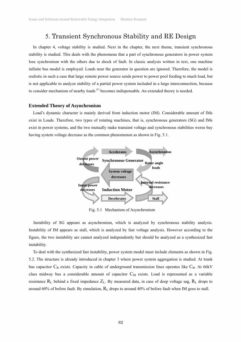
Load’s dynamic character is mainly derived from induction motor (IM). Considerable amount of IMs
exist in Loads. Therefore, two types of rotating machines, that is, synchronous generators (SG) and IMs
exist in power systems, and the two mutually make transient voltage and synchronous stabilities worse bay
having system voltage decrease as the common phenomenon as shown in Fig. 5.1.
Instability of SG appears as asynchronism, which is analyzed by synchronous stability analysis.
Instability of IM appears as stall, which is analyzed by fast voltage analysis. However according to the
figure, the two instability are cannot analyzed independently but should be analyzed as a synthesized fast
instability.
To deal with the synthesized fast instability, power system model must include elements as shown in Fig.
5.2. The structure is already introduced in chapter 3 where power system aggregation is studied. At trunk
bus capacitor CB exists. Capacity in cable of underground transmission lines operates like CB. At 66kV
class midway bus a considerable amount of capacitor CM exists. Load is represented as a variable
resistance RL behind a fixed impedance ZL. By measured data, in case of deep voltage sag, RL drops to
around 60% of before fault. By simulation, RL drops to around 40% of before fault when IM goes to stall.
Synchronous Generator
Induction Motor
Accelerates
Decelerates
Asynchronism
Stall
Input power
Output power
Internal resistance
Rotor angle
System voltage
Fig. 5.1 Mechanism of Asynchronism
decreases
decreases
decreases
decreases
leads
Page 2
Issues and Solutions around Renewable Energy Integration Shintaro Komami
83
The power system model is further more complex than 1 machine infinite bus model, but analysis is still
possible. Influence of dynamic load with variable internal resistance RL can be recognized by drawing
multiple power-angle (P-) curves for some values of RL as parameter.
On one hand, load branch impedances ZM and ZL hinder power consumption in resistance RL when
system voltage decreases. Reduced power consumption in load produces excessive power, which
accelerates SG. On the other hand, load is obstructed to receive power, and as the result, IM decelerates.
Thus, SG and IM go to instabilities. These unstable phenomena are hardly represented by traditional
aggregation ignoring load branch impedance, and as the result, such inadequate aggregation will
inadequately assess stability optimistically.
Partial load drop due to voltage sag has a negative effect that reduced load consumption power
accelerates SG and makes synchronous stability worse, and has a positive effect that fast load voltage
recovery also recovers load consumption power and makes voltage stability better. Which effect is stronger
must be studied by minute simulation.
Main theme of the chapter is what impacts on transient synchronous stability become serious when
renewable energy (RE) highly penetrates. Since RE (especially PV) locates near load, load’s dynamics such
as IM and accurate aggregation of load system become indispensable.
Minimum model for fast instability study considering RE is shown in Fig. 5.3. RE is expresses as
negative constant conductance GRE and variable susceptance BRE in parallel to load terminal. Of course
expressions by constant current, constant power or voltage source are possible. However, it is convenient
for power system that RE output decreases when system voltage becomes low, negative conductance model
Generator
VG∠G ZG VB ZS VS∠0
Infinite bus PG PS
CB ZM ZL RL
PL
Trunk bus
CM Load
Fig. 5.2 Minimum model for fast instability analysis
Midway bus
Generator
VG∠G ZG VB ZS VS∠0
Infinite bus
CB ZM ZL XI RL
PL
PG PS
Trunk bus CM
Dynamic load
BRE
GRE
Fig. 5.3 Minimum model of fast instability considering RE
CL
Load bus
Renewable E.
Page 3
Issues and Solutions around Renewable Energy Integration Shintaro Komami
84
is adopted that has the effect most. RE penetrates by 20% of load. Some thermal generators stop because of
demand supply balance. Three types of RE design are assumed.
“Drop type” RE once shuts down due to voltage sag. Until it reintegrates, voltage collapse may occur.
“FRT (Fault Ride-Through) type RE never shuts down due to voltage sag, but never support system
voltage recovery.
“DVS (Dynamic Voltage Support) type RE never shuts down due to voltage sag, and supports system
voltage recovery.
Power-voltage characters of DVS type RE are assumed as follows. Here, YRE0 is admittance at rated
power output.
When stabilities are calculated using power system model made from viewpoint of fast instability that
synthesizes classic asynchronism and fast voltage collapse, unstable cases appears one after another, which
were recognized as stable in traditional analyses. Those cases may become reality in today’s power system.
But further comments are postponed.
Is Inertia of Generator Indispensable?
Most RE interconnects through inverter, which has not large inertia such as SG. Taking is as reason RE is
very often remarked as inferior power source. However, the remark is not verified or falsified yet, although
it is possible. The attitude is that of pseudo-science. Therefore, the author as representative does it and
solves misunderstanding in electric engineering field.
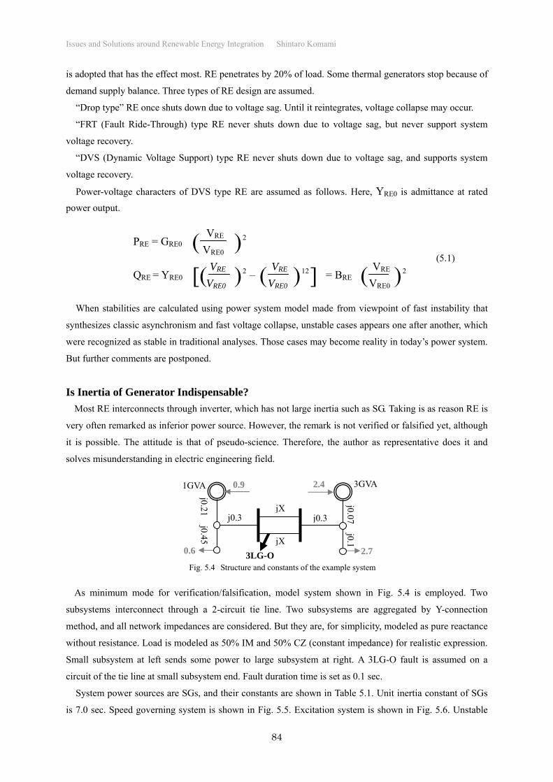
As minimum mode for verification/falsification, model system shown in Fig. 5.4 is employed. Two
subsystems interconnect through a 2-circuit tie line. Two subsystems are aggregated by Y-connection
method, and all network impedances are considered. But they are, for simplicity, modeled as pure reactance
without resistance. Load is modeled as 50% IM and 50% CZ (constant impedance) for realistic expression.
Small subsystem at left sends some power to large subsystem at right. A 3LG-O fault is assumed on a
circuit of the tie line at small subsystem end. Fault duration time is set as 0.1 sec.
System power sources are SGs, and their constants are shown in Table 5.1. Unit inertia constant of SGs
is 7.0 sec. Speed governing system is shown in Fig. 5.5. Excitation system is shown in Fig. 5.6. Unstable
PRE = GRE0 VRE
VRE0 ( )2
VRE
VRE0 VRE
VRE0 VRE
VRE0[( )2 ( ) ] ( ) 2 QRE = YRE0 – = BRE 12
(5.1)
0.6
j0.21 j0.45
j0.3 jX
jX
j0.3
2.7
0.9 2.4 1GVA 3GVA
j0.07 j0.1
3LG-OFig. 5.4 Structure and constants of the example system
Page 4
Issues and Solutions around Renewable Energy Integration Shintaro Komami
85
phenomenon is performed on simulation using CRIEP Y-method by enlarging tie line reactance X (for 1
circuit).
[ Synchronous Generator ] Increasing X up to 0.7, unstable phenomenon appears as shown in
Fig. 5.7. Although Generator output in subsystem 1 (PG1) considerably decreases sue to voltage sag during
fault, Prime mover torque in subsystem 1 (TG1) hardly varies. As the result, excessive power is
accumulated in inertia and phase angle (AG1) leads. In the example the first swing is still within stability
but the second swing goes to instability.
[ Very Light Synchronous Generator ] Inertia of SGs are set as very small. SG constants,
excitation system, and tie line reactance are same of normal inertia case. However, speed governing system
is changed as Fig. 5.8. The reason is as follows. When large contingency occurs, generator cannot send
power from prime mover. For solving the problem, a control that makes prime mover torque (TG) follow
generator output in a short time. As the result, some part of prime mover power is abandoned. In truth,
Table 5.1 Constants of the SGs
Xd Xd’ Xd” Td’ Td” Xq Xq’ Xq” Tq’ Tq” Ta
1.7 0.3 0.25 1.0 0.03 1.7 0.6 0.25 0.3 0.03 0.19
Fig. 5.5 Speed governing system
25
1+0.2s
1
1+0.2s
TG0
1
1+0.25s
1
1+9s0.7
0.3
TG
S-Ry CV HP RH, ILP
1
1+0.02s
VG
VG0
1+0.4s
1+4s
EF0 200 6
1+0.01s -4
EF
-2s
1+2s
PG 1+0.2s
1+0.5s
1+0.05s
1+0.1s
0.05
-0.05 1.0
Fig. 5.6 Excitation system
Fig. 5.7 Stability limit of SG
Page 5
Issues and Solutions around Renewable Energy Integration Shintaro Komami
86
when AC output of PV decreases, DC voltage rises, and solar panel output decreases. Therefore, the control
is sufficiently realistic.
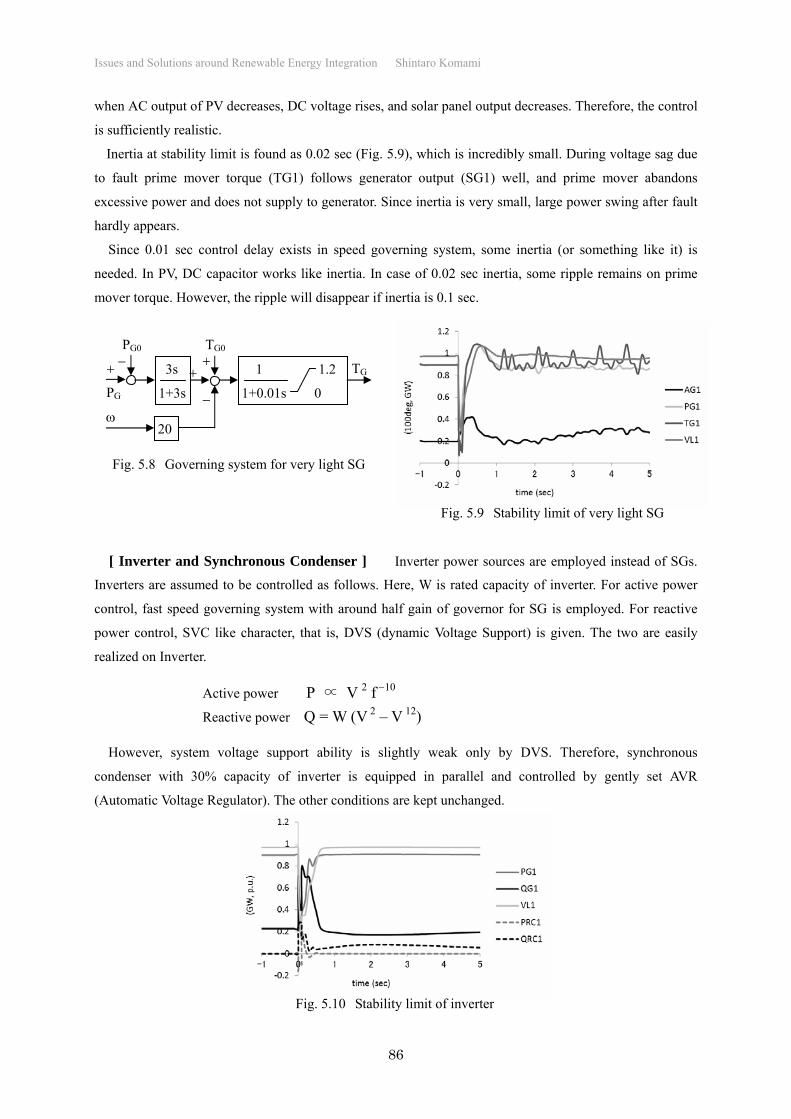
Inertia at stability limit is found as 0.02 sec (Fig. 5.9), which is incredibly small. During voltage sag due
to fault prime mover torque (TG1) follows generator output (SG1) well, and prime mover abandons
excessive power and does not supply to generator. Since inertia is very small, large power swing after fault
hardly appears.
Since 0.01 sec control delay exists in speed governing system, some inertia (or something like it) is
needed. In PV, DC capacitor works like inertia. In case of 0.02 sec inertia, some ripple remains on prime
mover torque. However, the ripple will disappear if inertia is 0.1 sec.
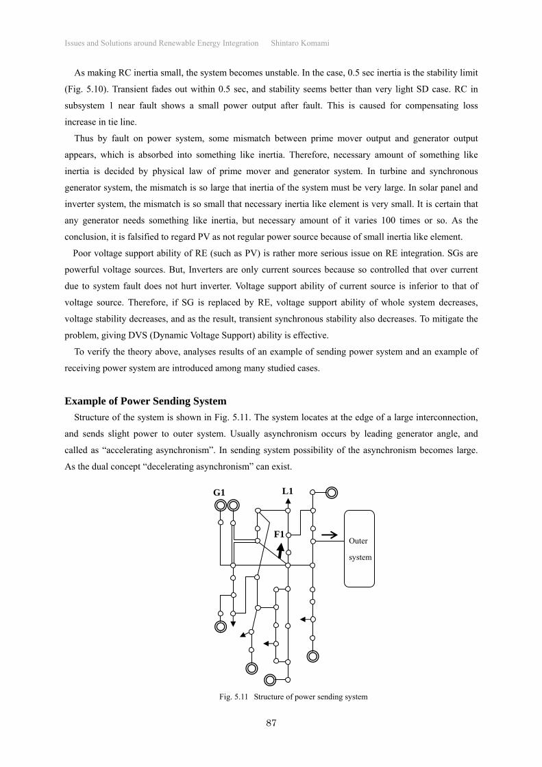
[ Inverter and Synchronous Condenser ] Inverter power sources are employed instead of SGs.
Inverters are assumed to be controlled as follows. Here, W is rated capacity of inverter. For active power
control, fast speed governing system with around half gain of governor for SG is employed. For reactive
power control, SVC like character, that is, DVS (dynamic Voltage Support) is given. The two are easily
realized on Inverter.
However, system voltage support ability is slightly weak only by DVS. Therefore, synchronous
condenser with 30% capacity of inverter is equipped in parallel and controlled by gently set AVR
(Automatic Voltage Regulator). The other conditions are kept unchanged.
3s
1+3s
1 1.2
1+0.01s 0
20
PG
PG0
TG0
TG
Fig. 5.8 Governing system for very light SG
Active power P ∝ V 2 f 10
Reactive power Q = W (V 2 – V 12)
Fig. 5.9 Stability limit of very light SG
Fig. 5.10 Stability limit of inverter
Page 6
Issues and Solutions around Renewable Energy Integration Shintaro Komami
87
As making RC inertia small, the system becomes unstable. In the case, 0.5 sec inertia is the stability limit
(Fig. 5.10). Transient fades out within 0.5 sec, and stability seems better than very light SD case. RC in
subsystem 1 near fault shows a small power output after fault. This is caused for compensating loss
increase in tie line.
Thus by fault on power system, some mismatch between prime mover output and generator output
appears, which is absorbed into something like inertia. Therefore, necessary amount of something like
inertia is decided by physical law of prime mover and generator system. In turbine and synchronous
generator system, the mismatch is so large that inertia of the system must be very large. In solar panel and
inverter system, the mismatch is so small that necessary inertia like element is very small. It is certain that
any generator needs something like inertia, but necessary amount of it varies 100 times or so. As the
conclusion, it is falsified to regard PV as not regular power source because of small inertia like element.
Poor voltage support ability of RE (such as PV) is rather more serious issue on RE integration. SGs are
powerful voltage sources. But, Inverters are only current sources because so controlled that over current
due to system fault does not hurt inverter. Voltage support ability of current source is inferior to that of
voltage source. Therefore, if SG is replaced by RE, voltage support ability of whole system decreases,
voltage stability decreases, and as the result, transient synchronous stability also decreases. To mitigate the
problem, giving DVS (Dynamic Voltage Support) ability is effective.
To verify the theory above, analyses results of an example of sending power system and an example of
receiving power system are introduced among many studied cases.
Example of Power Sending System
Structure of the system is shown in Fig. 5.11. The system locates at the edge of a large interconnection,
and sends slight power to outer system. Usually asynchronism occurs by leading generator angle, and
called as “accelerating asynchronism”. In sending system possibility of the asynchronism becomes large.
As the dual concept “decelerating asynchronism” can exist.
F1
Fig. 5.11 Structure of power sending system
G1 L1
Outer
system
Page 7
Issues and Solutions around Renewable Energy Integration Shintaro Komami
88
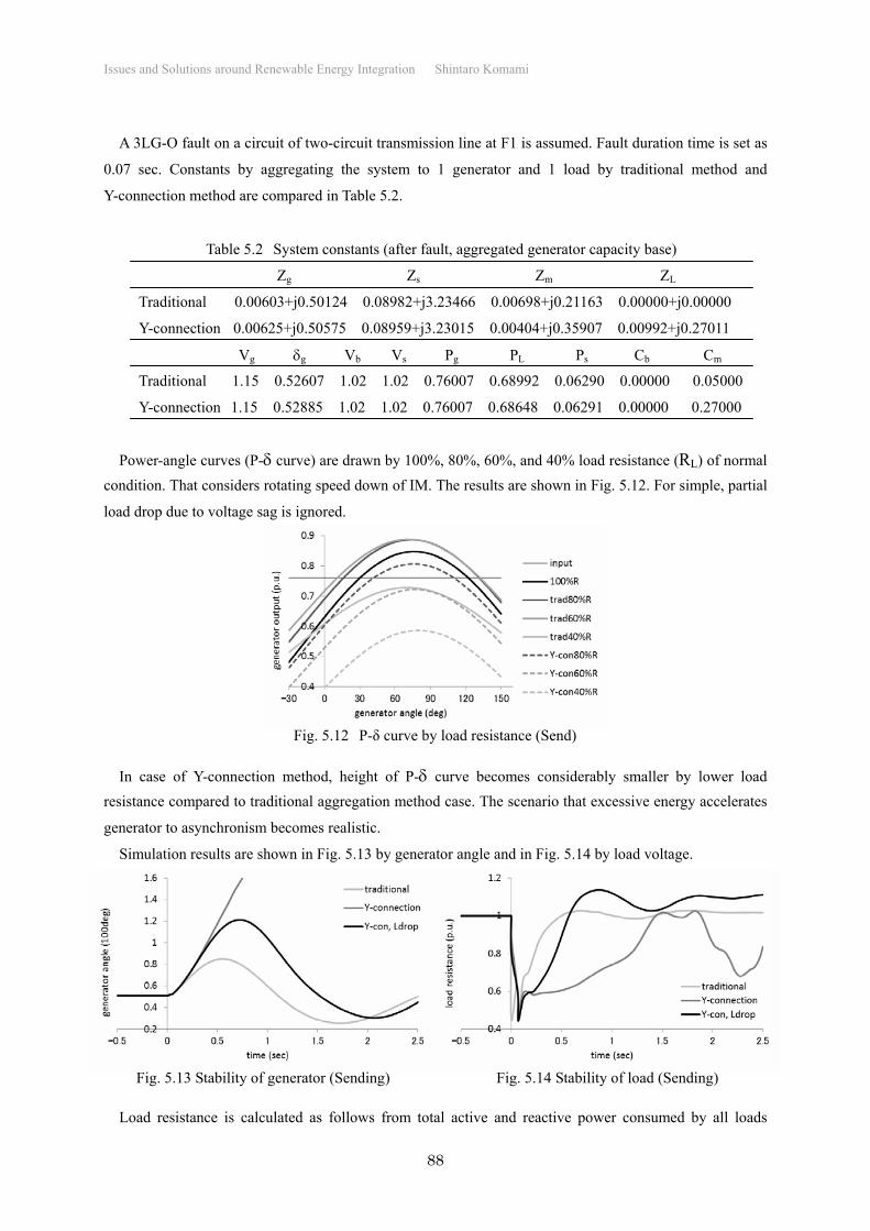
A 3LG-O fault on a circuit of two-circuit transmission line at F1 is assumed. Fault duration time is set as
0.07 sec. Constants by aggregating the system to 1 generator and 1 load by traditional method and
Y-connection method are compared in Table 5.2.
Power-angle curves (P- curve) are drawn by 100%, 80%, 60%, and 40% load resistance (RL) of normal
condition. That considers rotating speed down of IM. The results are shown in Fig. 5.12. For simple, partial
load drop due to voltage sag is ignored.
In case of Y-connection method, height of P- curve becomes considerably smaller by lower load
resistance compared to traditional aggregation method case. The scenario that excessive energy accelerates
generator to asynchronism becomes realistic.
Simulation results are shown in Fig. 5.13 by generator angle and in Fig. 5.14 by load voltage.
Load resistance is calculated as follows from total active and reactive power consumed by all loads
Table 5.2 System constants (after fault, aggregated generator capacity base)
Zg Zs Zm ZL
Traditional 0.00603+j0.50124 0.08982+j3.23466 0.00698+j0.21163 0.00000+j0.00000
Y-connection 0.00625+j0.50575 0.08959+j3.23015 0.00404+j0.35907 0.00992+j0.27011
Vg g Vb Vs Pg PL Ps Cb Cm
Traditional 1.15 0.52607 1.02 1.02 0.76007 0.68992 0.06290 0.00000 0.05000
Y-connection 1.15 0.52885 1.02 1.02 0.76007 0.68648 0.06291 0.00000 0.27000
Fig. 5.13 Stability of generator (Sending) Fig. 5.14 Stability of load (Sending)
Fig. 5.12 P-δ curve by load resistance (Send)
Page 8
Issues and Solutions around Renewable Energy Integration Shintaro Komami
89
Psum , Qsum , and weighted average load voltage Vave.
In case of traditional aggregation, generators keep easily stability even if neglecting partial load drop,
and load voltage recovers within 0.3sec. No sign of instability are seen. On the contrary in case of
Y-connection aggregation, 1.5 sec is needed for voltage recovery when neglecting partial load drop, and
during the period generators go to accelerating asynchronism. By considering partial load drop, recovering
time reduces to 0.6 sec and stability of generators is maintained. But slight over voltage due to load drop
appears after fault clear. Load resistance is around 60% of normal. At the resistance, top of P- curve is
lower than input in case of Y-connection (which means completely unstable), but higher than input in case
of traditional aggregation (which means possibility of stable operation).
Impacts of RE penetrated by 20% of load are assessed. Simulation results are shown in Fig. 5.15 and
5.16. Partial load drop is considered. In case of drop type RE, generator goes to accelerating asynchronism
and load goes to stall. Stability is quite ill. Impacts due to RE drop seem to be dominant in load voltage
recovery delay rather than in generator acceleration. In case of FRT type RE, stability is kept but voltage
recovery becomes slightly slower than no RE case. In case of DVS type RE, generator acceleration is
suppressed very small and load voltage recovery is very fast. Stability is quite sound.
Effective operation of DVS type RE is shown in Fig. 5.17. Load consumes much reactive power for
recovery around 0.3 sec after fault. The reactive power is almost compensated by DVS type RE, because
Vave2 Psum
Psum2 + Qsum2 RL =
Fig. 5.15 Generator stability by RE design (send) Fig. 5.16 Load stability by RE design (send)
Fig. 5.17 Effective operation of DVS type RE (send)
Page 9
Issues and Solutions around Renewable Energy Integration Shintaro Komami
90
RE locates near load. In addition DVS absorbs excessive reactive power after load recovery and mitigates
over voltage of system.
As stated above, IM load operates as making load voltage unstable, and as the result, transient
synchronous stability is worse than ever believed even in case of power sending system. The risk of
instability cannot be assessed without employing 50% (or so) IM load and Y-connection aggregation. RE
improves (DVS type) or spoils (drop type) stability according to its design.
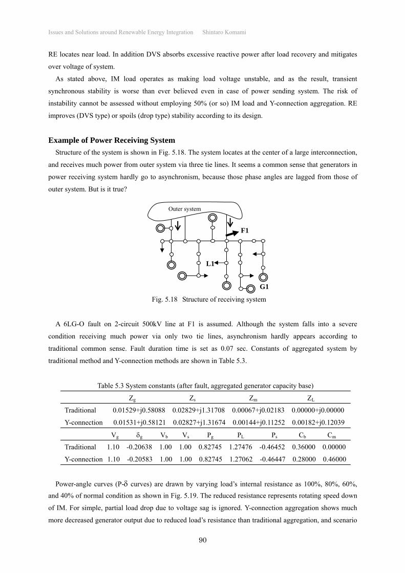
Example of Power Receiving System
Structure of the system is shown in Fig. 5.18. The system locates at the center of a large interconnection,
and receives much power from outer system via three tie lines. It seems a common sense that generators in
power receiving system hardly go to asynchronism, because those phase angles are lagged from those of
outer system. But is it true?
A 6LG-O fault on 2-circuit 500kV line at F1 is assumed. Although the system falls into a severe
condition receiving much power via only two tie lines, asynchronism hardly appears according to
traditional common sense. Fault duration time is set as 0.07 sec. Constants of aggregated system by
traditional method and Y-connection methods are shown in Table 5.3.
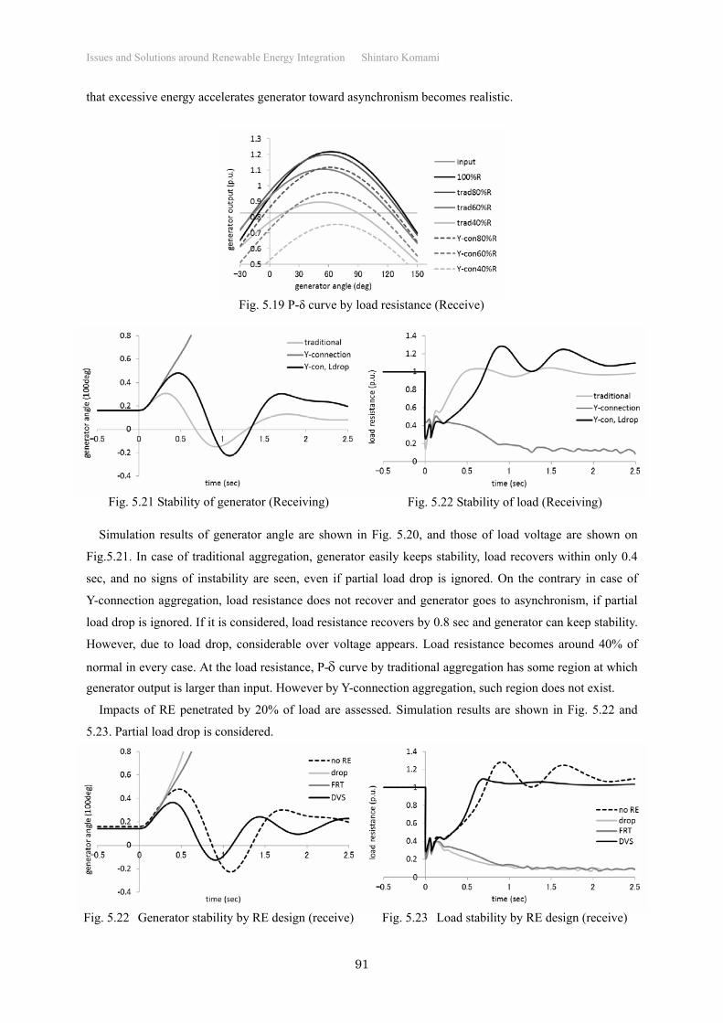
Power-angle curves (P- curves) are drawn by varying load’s internal resistance as 100%, 80%, 60%,
and 40% of normal condition as shown in Fig. 5.19. The reduced resistance represents rotating speed down
of IM. For simple, partial load drop due to voltage sag is ignored. Y-connection aggregation shows much
more decreased generator output due to reduced load’s resistance than traditional aggregation, and scenario
Fig. 5.18 Structure of receiving system
F1
G1
L1
Outer system
Table 5.3 System constants (after fault, aggregated generator capacity base)
Zg Zs Zm ZL
Traditional 0.01529+j0.58088 0.02829+j1.31708 0.00067+j0.02183 0.00000+j0.00000
Y-connection 0.01531+j0.58121 0.02827+j1.31674 0.00144+j0.11252 0.00182+j0.12039
Vg g Vb Vs Pg PL Ps Cb Cm
Traditional 1.10 -0.20638 1.00 1.00 0.82745 1.27476 -0.46452 0.36000 0.00000
Y-connection 1.10 -0.20583 1.00 1.00 0.82745 1.27062 -0.46447 0.28000 0.46000
Page 10
Issues and Solutions around Renewable Energy Integration Shintaro Komami
91
that excessive energy accelerates generator toward asynchronism becomes realistic.
Simulation results of generator angle are shown in Fig. 5.20, and those of load voltage are shown on
Fig.5.21. In case of traditional aggregation, generator easily keeps stability, load recovers within only 0.4
sec, and no signs of instability are seen, even if partial load drop is ignored. On the contrary in case of
Y-connection aggregation, load resistance does not recover and generator goes to asynchronism, if partial
load drop is ignored. If it is considered, load resistance recovers by 0.8 sec and generator can keep stability.
However, due to load drop, considerable over voltage appears. Load resistance becomes around 40% of
normal in every case. At the load resistance, P- curve by traditional aggregation has some region at which
generator output is larger than input. However by Y-connection aggregation, such region does not exist.
Impacts of RE penetrated by 20% of load are assessed. Simulation results are shown in Fig. 5.22 and
5.23. Partial load drop is considered.
Fig. 5.19 P-δ curve by load resistance (Receive)
Fig. 5.21 Stability of generator (Receiving) Fig. 5.22 Stability of load (Receiving)
Fig. 5.22 Generator stability by RE design (receive) Fig. 5.23 Load stability by RE design (receive)
Page 11
Issues and Solutions around Renewable Energy Integration Shintaro Komami
92
In case of drop type RE, generator goes to accelerating asynchronism and load goes to stall. Stability is
quite ill. In case of FRT type RE, stabilities are also quite ill like drop RE case. In case of DVS type RE,
generator acceleration is suppressed very small and load voltage recovery is very fast. Stability is quite
sound.
Effective operation of DVS type RE is shown in Fig. 5.24. Load consumes much reactive power for
recovery around 0.6 sec after fault. The reactive power is almost compensated by DVS type RE, because
RE locates near load. In addition DVS absorbs excessive reactive power after load recovery and mitigates
over voltage of system.
As stated above, even in case of power receiving asynchronism may occur triggered by IM load stall.
That is quite different from old common sense. The risk of instability cannot be assessed without
employing 50% (or so) IM load and Y-connection aggregation. RE improves (DVS type) or spoils (drop
type) stability according to its design.
Possibility of Transient Synchronous Instability
The author has only once seen transient synchronous instability in his 30 years of engineering life or
more. The instability occurred due to 77kV bus fault. For clearing the fault, around one sec is needed
because of primitive protection equipments in those days. During the time, a generator connecting to
154kV system went to asynchronism. But true criminal was another, which was OEL (Over Excitation
Limiter) setting. Usually OEL has several tens sec time delay, because field winding of synchronous
generator is wound on gigantic large iron rotor and temperature of the winding rises very slowly even if
over current occurs. It was astonishing that OEL of the generator was set as zero! As the result, by voltage
drop due to the 77kV bus fault field current increased, and OEL operated instantly. Field current of the
generator was quite reduced. Magnetic flux was also reduced. Thus, synchronism was lost. After the
accident, OEL setting has become ruled to be checked by power system engineering section.
A nightmare that SG and IM mutually make stabilities worse will come true when 3-phase-to-ground
fault (3G fault) occurs and IM largely decelerates. However, 3G fault can occur on trunk transmission
lines? Usually, lightning attacks transmission line with negative electric charge. Therefore, phases having
positive voltage against the earth tend to go flashover. Since at least one phase has negative voltage against
the earth. Only very large lightning will result 3G fault especially in extra high voltage transmission lines.
In addition in case of transmission line fault, the fault locates considerably far from substation bus usually.
Fig. 5.24 Effective operation of DVS type RE (receive)
Page 12
Issues and Solutions around Renewable Energy Integration Shintaro Komami
93
Considerable impedance exists from the bus to the fault. Shock by the fault must be easier than fault on the
bus itself. Therefore, synchronism is thought to be hardly lost by transmission line faults.
Transient synchronous instability can occur by fault on busses if it occurs. Two scenarios can be thought.
One is internal fault of 3-phase-type GIS (Gas Insulated Switchgear). Even if the fault occurs on a phase
conductor, it spreads to the other phase conductors within a half cycle (around 8 msec). Another is to
charge a bus having temporary grounding for safe working. That is a human error. The temporary
grounding must be put away before charging the bus. The two scenarios seem realistic. Human error can be
reduced by training and so on. However, fault possibility becomes in aged GIS. Low level of diagnosis
technique can cause GIS fault and following transient asynchronism, the author thinks.
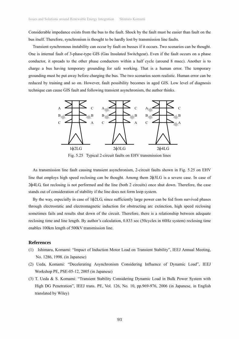
As transmission line fault causing transient asynchronism, 2-circuit faults shown in Fig. 5.25 on EHV
line that employs high speed reclosing can be thought. Among them 23LG is a severe case. In case of
24LG, fast reclosing is not performed and the line (both 2 circuits) once shut down. Therefore, the case
stands out of consideration of stability if the line does not form loop system.
By the way, especially in case of 12LG, since sufficiently large power can be fed from survived phases
through electrostatic and electromagnetic induction for obstructing arc extinction, high speed reclosing
sometimes fails and results shut down of the circuit. Therefore, there is a relationship between adequate
reclosing time and line length. By author’s calculation, 0.833 sec (50cycles in 60Hz system) reclosing time
enables 100km length of 500kV transmission line.
References
(1) Ishimaru, Komami: “Impact of Induction Motor Load on Transient Stability”, IEEJ Annual Meeting,
No. 1286, 1998. (in Japanese)
(2) Ueda, Komami: “Decelerating Asynchronism Considering Influence of Dynamic Load”, IEEJ
Workshop PE, PSE-05-12, 2005 (in Japanese)
(3) T. Ueda & S. Komami: “Transient Stability Considering Dynamic Load in Bulk Power System with
High DG Penetration”, IEEJ trans. PE, Vol. 126, No. 10, pp.969-976, 2006 (in Japanese, in English
translated by Wiley)
A
A
B B
C
C A
A
B B
C
C A
A
B B
C
C
12LG 23LG 24LG
Fig. 5.25 Typical 2-circuit faults on EHV transmission lines