+ All Categories
Home > Documents > 502-01/1.5-003-03 SERVICE MANUAL - Force Control

502-01/1.5-003-03 SERVICE MANUAL - Force Control

Date post: 09-Dec-2021
Category:
Upload: others
View: 1 times
Download: 0 times
Share this document with a friend
46
502-01/1.5-003-03 SERVICE MANUAL AND REPAIR PARTS FOR 01 and 1.5 Posidyne ® CLUTCH/BRAKE DRIVES With Split Clamp Quill Input Shaft WARNING - Read this manual before any installation, maintenance or operation. FORCE CONTROL INDUSTRIES, Inc. MANUFACTURERS OF MECHANICAL AND ELECTRICAL POWER TRANSMISSION EQUIPMENT
Transcript

502-01/1.5-003-03

SERVICE MANUAL AND

REPAIR PARTS FOR

01 and 1.5 Posidyne ®

CLUTCH/BRAKE DRIVES With Split Clamp Quill Input Shaft

WARNING - Read this manual before any

installation, maintenance or operation.

FORCE CONTROL INDUSTRIES, Inc.

MANUFACTURERS OF MECHANICAL AND

ELECTRICAL POWER TRANSMISSION EQUIPMENT

Limited Warranty

Force Control Industries, Inc. ("Force Control") warrants its products to be free from defects in mate-

rial and workmanship under normal and proper use for a period of one year from the date of ship-

ment. Any products purchased from Force Control that upon inspection at Force Control’s factory

prove to be defective as a result of normal use during the one year period will be repaired or

replaced (at Force Controls’ option) without any charge for parts or labor. This limited warranty shall

be void in regard to (1) any product or part thereof which has been altered or repaired by a buyer

without Force Control’s previous written consent or (2) any product or part thereof that has been

subjected to unusual electrical, physical or mechanical stress, or upon which the original identifica-

tion marks have been removed or altered. Transportation charges for shipping any product or part

thereof that the buyer claims is covered by this limited warranty shall be paid by the buyer. If Force

Control determines that any product or part thereof should be repaired or replaced under the terms

of this limited warranty it will pay for shipping the repaired or replaced product or part thereof back

to the buyer. EXCEPT FOR THE EXPRESS WARRANTY SET OUT ABOVE, FORCE CONTROL

DOES NOT GRANT ANY WARRANTIES EITHER EXPRESSED OR IMPLIED, INCLUDING

IMPLIED WARRANTIES OF MERCHANTABILITY OR FITNESS FOR USE. The warranty obliga-

tion set forth above is in lieu of all obligations or liabilities of Force Control for any damages. Force

Control specifically shall not be liable for any costs incurred by the buyer in disconnecting or re-

installing any product or part thereof repaired or replace under the limited warranty set out above.

FORCE CONTROL EXPRESSLY EXCLUDES ALL LIABILITY FOR ANY INDIRECT OR CONSE-

QUENTIAL DAMAGES THE BUYER MAY SUSTAIN IN CONNECTION WITH THE DELIVERY, USE,

OR PERFORMANCE OF FORCE CONTROL PRODUCTS. Under no circumstances shall any lia-

bility for which Force Control is held responsible exceed the selling price to the buyer of the Force

Control products that are proven to be defective. This limited warranty may be modified only in writ-

ing signed by a duly authorized officer of the company. This limited warranty applies exclusively to

Force Control products; warranties for motors and gear reducers and other component parts may

be provided by their respective manufactures. Any legal action for breach of any Force Control war-

ranty must be commenced within one year of the date on which the breach is or should have been

discovered.

A Return Goods Authorization (RGA) number must be obtained from the factory and clearly marked

on the outside of the package before any equipment will be accepted for warranty work. Force

Control will pay the shipping costs of returning the owner parts that are covered by warranty.

Force Control believes that the information in this document is accurate. The document has been

carefully reviewed for technical accuracy. In the event that technical or typographical errors exist,

Force Control reserves the right to make changes to subsequent editions of this document without

prior notice to holders of this edition. The reader should consult Force Control if errors are sus-

pected. In no event shall Force Control be liable for any damages arising out of or related to this

document or the information contained in it.

01 and 1.5 Posidyne CLUTCH/BRAKE

Section 1 DESCRIPTION and OPERATION

1-1 The Oil Shear Principle............................................... 1

1-2 Description ................................................................. 1

1-3 Operation .................................................................... 2

Section 2 SPECIFICATIONS

2-1 Model Designations .................................................... 3

2-2 Operating Specifications ............................................. 3

2-3 Dimensional Specifications ......................................... 4

A. With Split Clamp Quill Input Shaft .......................... 4

B. With Extended Male Input Shaft ............................. 5

Section 3 INSTALLATION

3-1 Receiving the Drive Unit ............................................. 6

3-2 Mounting the Drive Unit .............................................. 6

A. With Split Quill Input Shaft ...................................... 6

3-3 Pneumatic Hookup ..................................................... 6

3-4 Electrical Hookup........................................................ 7

Section 4 LUBRICATION

4-1 Checking the Oil Level .................................................. 8

4-2 Changing the Oil ......................................................... 8

4-3 Type of Oil .................................................................. 8

Section 5 OPERATIONAL CHECKS

5-1 General Setup Instructions ......................................... 9

5-2 Checking Clutch/Brake Piston Seals .......................... 9

5-3 Checking Clutch/Brake Engagement or

Input Shaft Vs. Output Shaft Rotation ......................... 9

5-4 Drive Motors ............................................................... 9

5-5 Pneumatic Control ...................................................... 9

Section 6 TROUBLESHOOTING

6-1 Troubleshooting Chart ................................................ 10

6-2 Checking Brake and Clutch Stacks for Wear .............. 12

Section 7 DISASSEMBLY

7-1 General Disassembly Procedure ............................... 13

7-2 Disconnecting the C-Face Motor ............................... 13

7-3 Removing Cooling Fan from the Input Shaft .............. 13

7-4 Removal and Disassembly of Optical Encoder .......... 13

7-5 Access to the Clutch and Brake Stacks ..................... 15

7-6 Split Clamp Quill Input Shaft Removal....................... 15

7-7 Quill Input Shaft Disassembly .................................... 15

7-8 Male Input Shaft Disassembly ................................... 16

7-9 Output Shaft Removal and Disassembly ................... 16

7-10 Removing Oil Seals ................................................. 17

7-11 Piston Housing Subassembly Disassembly ............. 17

Section 8 CLEANING and INSPECTION

8-1 Cleaning and Inspection. ........................................... 18

8-2 Repair and Replacement .......................................... 18

Section 9 REASSEMBLY

9-1 General Reassembly Instructions ............................. 19

9-2 Reassembly of the Piston

Housing Sub-Assembly ............................................ 19

9-3 Output Shaft Reassembly ......................................... 20

9-4 Input Shaft Reassembly ............................................ 20

9-5 Installing Oil Seals into Input

and Output Housings ................................................ 21

9-6 Installing Output Shaft into Output Housing .............. 21

9-7 Measuring and Controlling Stack Height ................... 21

9-8 Installing Brake Stack ................................................ 22

9-9 Installing the Piston Housing Assembly .................... 22

9-10 Installing Clutch Stack ............................................. 22

9-11 Installing Input Shaft and Input Housing.................. 23

9-12 Installing Cooling Fan on Input Shaft ...................... 23

9-13 Final Reassembly .................................................. 23

9-14 Remounting the Drive Unit

to the C-Face Motor ............................................... 23

Section 10 ORDERING REPAIR PARTS

10-1 General Information ................................................ 24

10-2 Drive Motors ............................................................ 24

10-3 Factory Rebuild Service .......................................... 24

10-4 Ordering Replacement Parts ................................... 24

10-5 Name Plate and Model Numbers ............................ 24

Model Numbers....................................................... 25

Exploded View Drawings

Figure 10.1 - 01 and 1.5 Posidyne Clutch/Brake Unit

(With Split Clamp Quill Input Shaft) ........................... 27

Figure 10.2 - Piston Housing and

Retainer Sub-Assembly ............................................ 29

Figure 10.3 - Optional Extended Male Input Shaft .......... 31

Figure 10.3 - Optional 8-1/2" AK C-Face Adapter ........... 31

Figure 10.4 - Optional Manifold

Mounted Control Valves ................................................. 33

Figure 10.4 - Optional Optical Encoder Assembly ........... 33

Figure 10.5 - Optional Fan Cooling ................................. 34

Figure 10.6 - Optional Foot Mounting .............................. 35

Figure 10.7 - Clutch/Brake Stacks (Vertical Installation) ..36

Figure 10.8 - Vertical Installation Kits .............................. 37

Special Assembly Tools

Size 01 Posidyne Special Assembly Tools ........................... 38

Size 1.5 Posidyne Special Assembly Tools .......................... 40

Revision History Manual Revision History .................................................. 42

Section 1 DESCRIPTION and OPERATION

1-1 THE OIL SHEAR PRINCIPLE

Conventional clutches and brakes depend on the friction

between solid surfaces operating in air to transmit torque.

Friction does the job, but produces a great amount of heat and

wear. The Posidyne Clutch/Brake units are oil shear drives,

with the friction surfaces operating in a bath of oil, the oil mol-

ecules tend to cling to each other and to the friction surfaces.

As moving and stationary elements are brought together, a

thin, but positive film of oil is maintained between them, con-

trolled by the clamping pressure and carefully designed

grooves in the elements. Torque is transmitted from one ele-

ment to the other through the viscous shear of the oil film. So

long as there is relative motion between the elements, they are

protected by the oil, thus greatly reducing wear. The oil bath

also effectively transmits heat away from the friction elements.

1-2 DESCRIPTION (See Figure 1.1)

In the Posidyne Clutch/Brakes, the friction surfaces consist of

alternate carbon steel plates and advanced friction material on

steel discs. The oil control grooves are molded into the friction

material disc surfaces. The discs have internal teeth which

mate with a spline on the output shaft for both clutch and brake

applications. The steel plates are pinned to the input shaft in

the clutch and the housing for the brake when used. The

splined sections of the Posidyne output shaft contain centrifu-

gal impellers to maintain a positive flow of oil between the

discs and plates.

Figure 1.1 - 01 and 1.5 Posidyne Clutch/Brake Description

Force Control Industries, Inc. 1

As noted in Section 2, Specifications, standard Posidyne units

may be equipped with a clutch and a brake, or a clutch only.

The Clutch is normally operated by compressed air, although

hydraulic pressure can be used. The Posidyne brake may be

pressure operated, or it may be spring loaded to operate auto-

matically when the clutch is released.

1-3 OPERATION

The Posidyne cross-section (Figure 1.2) shows the drive with

the Brake engaged. A nominal braking force is provided by

springs located in the Piston Housing. Heavier springs are

used to provide a greater braking force, when needed. Air

Assist (as shown), controlled by external valves, also provides

a greater braking force. The drive is normally in the Brake

Position. The Drive Plates are pinned to the Output Housing

and the Friction Discs are splined to the Output Shaft. The

Output Shaft is not able to rotate in the Brake Position.

The Clutch is engaged when the air pressure is exhausted

from the Brake Port and applied to the Clutch Port. The Piston

moves to compress the Clutch Stack on the Input Shaft. The

Drive Plates are pinned to the Input Shaft and the Friction

Discs are splined to the Output Shaft. This allows both shafts

to rotate at the same speed.

Figure 1.2 - 01 and 1.5 Posidyne Clutch/Brake Operation

2 Force Control Industries, Inc.

2-1 MODEL DESIGNATIONS

Section 2 SPECIFICATIONS

NOTE: Type A and B units both have spring actuated

The model designations specifies the size (01 and 1.5) and

type of unit. The types are:

S - Air set clutch, light spring set brake with air assist.

SA - Air set clutch, medium spring set brake with air

assist.

A - Air set clutch, medium spring set brake. (See

NOTE following).

B - Air set clutch, heavy spring set brake. (See NOTE

following).

C - Air set clutch, no brake.

brakes. The difference is that type B units have addi-

tional springs.

2-2 OPERATING SPECIFICATIONS

Specifications for the Posidyne Clutch/Brake Drives are listed

in the following Specification Table.

TORQUE RATINGS

The Torque Ratings are based on maximum actuation pres-

sure.

OPERATING SPECIFICATIONS

Size

Logic

Max. Clutch Torque (Lb. In.)

Max. Brake Torque (Lb. In.)

Max

RPM

Max

KE per

Engmt.

(Ft. Lbs.)

Avg. Therm.

H.P.*

Air

Vol. per

Engmt.

(Cu. In.)

Oil

Cap.

(Qts.)

Inertia

of Cyclic

Parts

(Lb. Ft.2) Static Dyn.

*Max

Air Pr.

Springs Only With Air Assist Cooling

Static Dyn. Static Dyn. *Max Air Pr. Basic Fan Horiz Vert

01

S 108 93 60 psi 11 9 131 113 60 psi

3600

2987

Horiz.

.15 .45

Vert.

--- ---

.40

1.5

2

.005

SA 110 95 70 psi 25 22 100 86 38 psi

A 100 86 80 psi 33 28 --- --- ---

B 62 53 80 psi 67 58 --- --- ---

C 106 91 70 psi --- --- --- --- ---

P 104 90 60 psi --- --- 104 90 60 psi

1.5

S 427 367 60 psi 32 27 484 416 60 psi

3600

11,230

Horiz.

.25 .55

Vert.

--- ---

.50

2.0

2.5

.012

SA 387 333 70 psi 110 95 492 423 70 psi

A 387 333 70 psi 110 95 --- --- ---

B 240 206 70 psi 220 189 --- --- ---

C 427 367 60 psi --- --- --- --- ---

P 464 399 70 psi --- --- 464 399 70 psi

* - Listed air pressures are at maximum. Operating pressures

are generally much lower.

OVERHUNG LOAD CAPACITY (Lbs. Pull)**

Size

Male Input Shaft Output Shaft

300 RPM

1200 RPM*

1800 RPM

3600 RPM

300 RPM 1200 RPM 1800 RPM 3600 RPM

Without Encoder

With Encoder

Without Encoder

With Encoder

Without Encoder

With Encoder

Without Encoder

With Encoder

01 250 160 140 110 175 99 175 99 175 99 140 79

1.5 275 175 150 120 360 245 360 245 335 235 265 186

** - At midpoint of shaft extension.

Force Control Industries, Inc. 3

2-3 DIMENSIONAL SPECIFICATIONS (Inches)

A. DIMENSIONS (With Split Clamp Quill Input Shaft (Inches)

Posidyne SIZE

INPUT/ OUTPUT MODULE

INPUT OUTPUT OTHER DIMENSIONS (APPROX.)

M Q (MAX) R FU U V AA AB BA BB L

01

2 .56

.219

.19 .625 .625 2.062 7.57

3.94

4.44

8.00

7.63

3 .28 .875 .875 2.125

1.5

2 .66

2.39

.19 .625 .625 2.062 8.67

4.42

5.03

8.95

9.00

3 .28 .875 .875 2.125

8-1/2” AK C-Face Flange (182 TC and 184 TC Motor Frame)

Dimensions are subject to change without notice. Certified Installation Drawings are available upon request.

4 Force Control Industries, Inc.

B. DIMENSIONS (With Extended Male Input Shaft)

Size In/Out

Module

Input Output Other Dimensions Foot Mounting

FU FV U V AB AL CC1 CC2 C1 C2 D1 O1 E 2F1 2F2 BSV D2 O2

01 1 7/8 2.13 7/8 2.13 4.00 3.63 7.62 --- 11.88 --- --- --- 3.75 4.50 --- 3.62 4.50 9.09

1.5 1 7/8 2.13 7/8 2.13 4.70 4.25 9.00 10.00 13.25 14.25 --- --- 3.75 5.38 6.63 3.81 4.50 9.93

Dimensions are subject to change without notice. Certified Installation Drawings are available upon request.

Force Control Industries, Inc. 5

3-1 RECEIVING THE DRIVE UNIT

Section 3

INSTALLATION 3. Loosen the Locking Collar (#281) which is only hand tight-

ened on the Split Quill Input Shaft (#2). Check the Drive Unit for shortages or damages immediately after arrival. Prompt reporting to the Carrier's Agent, with nota-

tions made on the Freight Bill, will expedite any adjustment

made by the Carrier.

When unloading or handling the Drive Unit, keep it upright. All

Drive Units are filled with oil, ready to run, when shipped.

However, before placing the Drive Unit in service or storage,

check the oil level to make sure none has spilled out in transit. Add oil if necessary. Refer to Section 4 LUBRICATION.

Remove the red plastic pipe plug from the Reducer Bushing

(#73) in the top of the Input Housing and install the Air

Breather (#45). Do not remove the Reducer Bushing on

units with Key Type Quill Input Shaft.

If the Drive Unit is not to be installed or operated soon after

arrival, store it in a clean dry place having a slow and moder-

ate change in ambient temperature.

3-2 MOUNTING THE DRIVE UNIT

A. With Split Clamp Quill Input Shaft (See Figure 3.1 and 10.1)

1. First make sure that the pilot diameter and mating surfaces of

the C-Face Flange is clean and free of all nicks, burrs or any-

thing that would not allow the Drive Unit to seat properly.

2. Install the (4) Mounting Spools (#221), (4) Lockwashers

(#265) and (4) Hex Hd. Screws (#305) to the C-Face

mounting surface. Apply Blue Loctite to the Screws (#305)

and only finger tighten at this time.

Figure 3.1 - 01 and 1.5 Posidyne Installation

6

4. Remove the drive motor key if there is one on the motor

shaft and install Key (#180), which is supplied with the

Posidyne.

IMPORTANT - Make sure that the motor shaft is

thoroughly cleaned but do not lubricate the shaft

with any oil. Torque transfer depends on friction

between the motor shaft and the split quill input

shaft.

5. Loosen the (4) Set Screws (#154) and slip the Drive Unit

onto the motor shaft with the Key (#180) aligned with the

keyway in the Input Shaft (#2). Push the Drive Unit until it

seats on the motor pilot diameter and the (4) Mounting

Spools (#221) are seated in the mounting cavities.

6. Carefully remove the Drive Unit without moving the posi-

tion of the spools. Torque the Screws (#305) to 216 In.

Lbs.

7. Remove the (2) Screws in the Locking Collar (#281) and

apply Blue Loctite #242 to them. Reinstall them back into

the Locking Collar (#281) loosely with the Locking Collar

(#281) in position on the Input shaft (#2).

8. Reposition the unit back on the C Face motor flange and tighten the (4) Set Screws (#154). Torque to 120 In. Lbs.

Visually check to see if the C Face mounting surfaces are

snug and tight all the way around.

9. Torque the (2) Screws in the Locking Collar (#281) to 144 In.

Lbs.

IMPORTANT NOTE - Whether or not you have an optional 8-

1/2" AK C-Face Flanges or Fan Cooling, this spool align-

ment procedure must be maintained to assure proper

mounting spool alignment and position.

3-3 PNEUMATIC HOOKUP

Figures 3.2 and 3.3 illustrate typical compressed air sys-

tems for the 01 and 1.5 Posidyne Clutch/Brake Unit.

Note the following when planning and installing the air

system:

1. Use direct acting solenoid air valves or pilot operated

valves to give the response speed required. Locate the

valves as close as possible to the air inlets on the Drive.

The valves may be installed directly on the drive if they are

supported. Manifold mounted control valves are available

as an option from the factory. Consult your representative

or the Force Control factory.

2. Be sure to use valves of at least .4 Cv.

3. The optional accumulator should be used for quick

response, particularly if the air line loss and the nature of

the air supply is such that recovery is slow. Size the accu-

mulator to be at least 10 times the air required per engage-

ment. (See Specification Chart.)

Force Control Industries, Inc.

4. Consult Force Control Factory if you are considering using

a Lubricator in the pneumatic supply line.

5. The air pressure regulator should be sized and set to pro-

vide the required torque. (See Torque Specifications.)

6. Pressure is directly proportional to torque. If 80 PSI is not

required to drive the machine, use only the air pressure

necessary . This will give additional life to the Clutch/Brake

Unit.

7. After using the drive for a few weeks the acceleration time

may increase. Increasing the air pressure will restore the

acceleration time.

Figure 3.2 - Air operated clutch and brake. (Posidyne - S and

SA Logics) with different actuation pressures for the clutch

and the brake.

Figure 3.3 - Air operated clutch only and spring set brake.

(Posidyne A, B and C Logics)

3-4 ELECTRICAL HOOK-UP

(For Mac 82 Series Control Valves Only)

Use the (2) yellow wires marked "A" for Solenoid "A". The (2)

red wires marked "B" are not used for a single clutch unit. They

can be cut off and capped.

Force Control Industries, Inc. 7

4-1 CHECKING THE OIL LEVEL (See Figure 4.1)

Section 4

LUBRICATION After the first oil change check the oil level and color of the oil

at least once per month. Maintain the oil level to the center of When the drive is installed and weekly thereafter, or until expe-

rience dictates otherwise, check the oil level. Always check

the oil level with the drive at room temperature and while it is

not running.

The drive has an oil sight gauge located at the input end of the

drive. The oil level is to show at the center of the gauge.

the sight glass by adding additional oil as needed. The oil

should be changed after every 12 months of operation or

sooner if the oil color darkens. High energy applications will

usually darken the oil sooner and require more frequent oil

changes. Low energy applications will usually not darken the

oil.

4-2 CHANGING THE OIL (See Figure 4.1)

IMPORTANT : Open the disconnects to the drive

motors before attempting to change the oil.

After the first 30 days of operation completely drain the oil from

the drive using the drain plugs provided. If the oil sight glass is

dirty it should be removed and cleaned.

Reinstall the drain plugs and refill the drive to the center of the

sight glass with fresh oil.

CAUTION: Do not overfill the Drive Unit. Excess oil

will cause the unit to overheat.

4-3 TYPE OF OIL

Use only Mobil Automatic Transmission Fluid ATF-210 (Type

“F”) or Mobil Multi-purpose Automatic Transmission Fluid for

most drives. Other fluids may be specified for special applica-

tions. Always use the type of fluid specified on the Name

Plate.

HORIZONTAL

VERTICAL INPUT DOWN

VERTICAL INPUT UP

Figure 4.1 - Lubrication

8 Force Control Industries, Inc.

These Operational Checks are to be made when the Drive Unit is removed from service for repair. Provisions for manually

controlled 60 to 80 PSI air pressure must be made for these

Operational Checks.

5-1 GENERAL SET-UP INSTRUCTIONS

Assemble a Pneumatic Testing Set-Up similar to the one

shown in Figure 5.1

5-2 CHECKING CLUTCH AND

BRAKE PISTON SEALS

1. Hook the Pneumatic Testing Setup to the Clutch Port and

apply shop air to it.

2. Crack the Shut-off Valve until the air pressure reads about

80 PSI on the Pressure Gauge and then quickly shut the

air off.

3. Observe the Pressure Gauge to see if the air pressure

stays the same, or drops. If the pressure stays the same or

drops slowly, the Piston Seals are okay. If the pressure

drops rapidly (more than 5 PSI per minute), the Piston

Seals are leaking and will need to be replaced.

4. Disconnect the shop air and exhaust the air pressure from

the drive unit.

(S and SA Logic Only) "Air Assist " to Brake

5. Hook the Pneumatic Testing Setup to the Brake Port and

apply shop air to it.

6. Repeat Steps 2, 3 and 4.

5-3 CHECKING CLUTCH AND BRAKE ENGAGEMENT

OR INPUT SHAFT Vs. OUTPUT SHAFT ROTATION.

(WITH C-FACE MOUNTED DRIVE MOTORS)

If the C-Face mounted Drive Motors are still attached, then the Input Shaft is not accessible to be manually rotated to check

Clutch/Brake Engagement and Input Shaft vs. Output Shaft

rotation.

1. Temporarily hook-up Drive Motor and “Bump” it to check

the Clutch or Brake Operating Modes and Output Shaft

rotation.

CAUTION: Do not attempt to run motors with the

Inspection Plug removed. They must first be

replaced.

5-4 DRIVE MOTORS

Check wiring connections against the wiring diagram on the

Name Plate. “Bump” the motor and check direction of rotation.

Check all connections for tightness.

5-5 PNEUMATIC CONTROL

The Pneumatic Control Operational Checks are to be made

with Pneumatic Control valves hooked up.

(See Figures 3.2 and 3.3 for appropriate Pneumatic Control

Diagrams.)

1. Shut off air supply, lock it out, and bleed off any trapped air

in the system.

2. Insert Diagnostic Pressure Gauges in the air supply

between the control valves and the drive. Turn air supply

back on.

3. Activate Solenoid Control Valves for desired function.

A. Clutch Drive

B. Brake “Air Assist

4. Check air pressure with installed diagnostic pressure

gauges for each function.

5. Check all electrical connections and the solenoid operation

per manufacturer's specifications.

Figure 5.1 - Pneumatic Testing Set-Up

Force Control Industries, Inc. 9

6-1 TROUBLESHOOTING CHART

Section 6

TROUBLESHOOTING

TROUBLE POSSIBLE CAUSE REMEDY

Both clutch and brake fail to engage

properly.

Electrical control circuit.

Check control circuit.

Low air pressure. Increase air pressure.**

Air pressure regulator or piping. Check for improper operation or leaks.

Worn friction surfaces. Check parts for wear and replace if

necessary. (See Section 6-2)

Clutch fails to engage properly. Electrical control circuit. Check control circuit.

Valve not functioning properly. Check valve operation. Replace if

necessary.

Internal air leakage. Check and replace O-Rings and Liners

if necessary.

Low air pressure Increase air pressure.**

Worn friction surfaces. Check parts for wear and replace if

necessary. (See Section 6-2)

Picks up load too quickly. Air pressure too high. Reduce air pressure.

Low oil level. Check oil level and add if necessary.

Clutch fails to disengage properly. Electrical control circuit. Check control circuit.

Valve not functioning properly.

Piston sticking-broken return springs.

Check and replace valve if necessary.

Disassemble to extent necessary and

inspect for damaged parts.

Noise and vibration Mounted on poor foundation. Improve installation. Tighten foot bolts.

Misaligned couplings. Recheck alignment.

Damaged bearings. Disassemble to extent necessary and

inspect for damaged bearings.

Noise without load (With C-Face Motor)

Slight noise or rattling sound in the input end

of a C-Face unit when the drive motor is

running in an unloaded condition. If the motor

is AC variable speed it may be louder at

certain speeds.

This is a normal condition. The input shaft is

loosely supported in order to compensate for

motor shaft run-out and out of round conditions

of the pilot.. Some noise can be generated by

the movement of the input shaft & drive plates.

This is not a harmful condition to the clutch/

brake, and will not cause premature wear.

Noise with load (With C-Face DC Motor)

Slight noise or chatter coming from the input

end of a C-Face unit when the drive motor is

DC and is running in a loaded condition. Noise

exists only when the motor is loaded under

certain conditions.

This is a normal condition of the motor and is

not in the clutch/brake unit. The harmonics of

the DC motor is transmitted to the clutch/brake

housing and sounds as if it was coming from

the clutch/brake.

This is not a harmful condition to the clutch/

brake, and will not cause premature wear.

10 Force Control Industries, Inc.

6-1 TROUBLESHOOTING CHART (Continued)

TROUBLE POSSIBLE CAUSE REMEDY

Brake fails to engage properly.

Electrical control circuit.

Check control circuit.

Valve not functioning properly. Check valve operation. Replace if

necessary.

Internal air leakage. Check and replace O-Rings and Liners

if necessary.

Low air pressure Increase air pressure.**

Worn friction surfaces. Check parts for wear and replace if

necessary. (See Section 6-2)

Piston sticking Disassemble to extent necessary and

inspect for damaged parts

Weak or broken brake spring Replace spring

Drive overheats.

(Oil temp. above 225° F.)

Inertia or resistance changed. Check with Force Control engineering.

Improper oil level. Check oil level. Add or drain as needed.

Fan blocked. Clean shroud.

Oil leakage Oil seal lips damaged. Check to see if oil is leaking around

shaft and replace if necessary.

Gaskets Tighten all external bolts.

Poor ventilation. Remove breather and clean.

Oil leakage out breather. Damaged seal around piston. Disassemble and repair.

Oil level too high. Drain excess oil.

Excessive shaft end play.

Clutch or brake does not repeat.

Bearings bad. Disassemble and replace.

Air pressure changed. Check air pressure and adjust.

*Oil temperature changed. Check temperature.

Resistance in machine changed. Lubricate bearings.

* - For installations requiring precise starting and stopping, operating temperatures are important. Operating temperatures between

116° F. and 165° F. are recommended. If the transmission fluid is allowed to drop to ambient temperatures overnight, the clutch input

shaft should be run approx. 1/2 hour before operating the machinery

** - Maximum Air Pressure. (See Section 2 Specifications Chart for maximum operating air pressure.)

Force Control Industries, Inc. 11

6-2 CHECKING BRAKE and

CLUTCH STACKS for WEAR

An easy procedure has been established to visually check the

Clutch and Brake Stacks for Wear to determine whether or not they need replaced. There is a projection on the back-face of

the Piston Housing (#10) to enable you to visually check this.

(See Figure 6.1)

CAUTION: Disconnect and lockout all electrical

power to the drive motor. This step must be taken

to avoid any possibility of personal injury or dam-

age to the unit.

1. Remove the Inspection Plug (#72) from the top of the Input

Housing.

2. Apply air pressure to the clutch port and with a flashlight

observe the position of Surface "A" of the Piston. If this sur-

face "A" is flush with Surface "C" the Clutch Stack is worn

and needs to be replaced. (See Figure 6.1)

3. Apply air to the brake port and again observe the position

of Surface "A" of the piston. If it is flush with Surface "B" of

the piston housing, the Brake Stack is worn and needs to

be replaced. (See Figure 6.1)

IMPORTANT NOTE: Even though the Clutch Stack and the

Brake Stack can, individually, be checked for wear, both

stacks should be replaced as a complete set if either stack

is worn and needs replaced. Refer to Section 7 Disassembly

and Section 9 Reassembly for Clutch and Brake Stack

Replacement.

Figure 6.1 - Checking Stack Wear

12 Force Control Industries, Inc.

7-1 GENERAL DISASSEMBLY PROCEDURE

Section 7 DISASSEMBLY

1. Loosen the (4) Cone Point Set Screws (#154) in the Input

Housing enough so the Drive Unit can be removed from the 1. Disconnect the Drive Unit and move it to a suitable work

area. See Section 7-2 to disconnect the drive motor from

the unit.

2. Disconnect all necessary pneumatic piping and valves.

3. Remove the Drain Plugs (#74) from the bottom of the Input

Housing and drain out all of the automatic transmission

fluid into a suitable container and either save or discard as

condition warrants.

NOTE: It is recommended that you set the drive unit

on the output end with the output shaft in vertical

down position for ease of disassembly. Also supply

suitable bracing and clamping to stabilize the drive

unit.

The 01 and 1.5 Posidyne Drive Unit is comprised of a Main

Assembly (Shown on Figures 10.1) and a Piston Housing Sub-

Assembly (Shown on Figure 10.2).

The Main Assembly consists of:

1. Input Housing and Input Shaft.

2. Clutch and Brake Stacks.

3. Piston Housing Sub-Assembly, which consists of:

a. Piston Housing, Liners and O-Rings.

b. Piston, Thrust Plate and Bearing.

c. Piston Retainer, Liners and O-Rings.

4. Output Housing and Output Shaft.

7-2 DISCONNECTING THE C-FACE DRIVE MOTOR

(Standard 4-1/2" AK Flange) (See Figure 7.1 and 10.1)

Figure 7.1 - Disconnecting the C-Face Motor

(4) Mounting Spools (#221), which are attached to the drive

motor. Loosen the (2) Screws in the Locking Collar (#281).

Pull the Drive Unit away from the motor, sliding the motor

shaft out of the Quill Input Shaft (#2). (See Figure 7.1)

(1.5 Posidyne Only With 8-1/2" AK Flange) (See Figures 7.1 and 10.3)

1. Loosen the (4) Cone Point Set Screws (#154) in the Input

Housing enough so the Drive Unit can be removed from

the (4) Mounting Spools (#239), which are attached to the

Mounting Flange (#200). Loosen the (2) Screws in the

Locking Collar (#281). Pull the Drive Unit away from the

flange and motor, sliding the motor shaft out of the Quill

Input Shaft (#2).

7-3 REMOVING COOLING FAN FROM INPUT SHAFT (With Male Extended Input Shaft) (See Figure 10.5)

1. Remove the drive pulley or coupling as per manufacturers

specifications.

2. Loosen the (4) Cone Pt Set Screws (#154) in the Input

Housing.

3. Pull the Fan Shroud (#24), along with the Mounting Screws

and Spools, off the Drive Unit.

4. Pry the Cooling Fan (#25) off the Input Shaft (#2) with (2)

pry bars in an even manner.

5. Remove and inspect the Tolerance Ring (#251). If it is dam-

aged then replace it with a new one. If it is okay then save

it for reassembly.

7-4 REMOVAL AND DISASSEMBLY OF OPTICAL

ENCODER (See Figure 10.4)

Any Drive Sheaves, Pulleys or Couplings must first be

removed from the output shaft.

1. Take out the (4) Screws (#225) and remove the Top Cover

(#372) and the upper Gasket (#19) from the Upper

Enclosure (#18). This gasket is reusable.

2. Pull the Insulator (#373) up and out of the Upper Enclosure

(#18).

3. Loosen the (2) captive screws in the Cable Connector

(#368) and unplug it from the Circuit Board (#355).

4. Pull the Cable Grommet (#260), Cable (#259) and Cable

Connector (#368) out of the Top Enclosure slot.

5. Remove the (2) Cap Screws (#77) and take the Upper

Enclosure (#18) and lower Gasket (#19) off of the Disc

Housing (#17). This gasket is also reusable.

6. Pull the Circuit Board (#355) straight up and out of the Disc

Housing (#17).

7. Remove the (4) Screws (#76) and (4) Lockwashers (#257)

pull the Disc Housing off the Posidyne mounting face.

Force Control Industries, Inc. 13

Figure 7.2 - Access to the Clutch Stack

Figure 7.3 - Access to the Brake Stack

14

Force Control Industries, Inc.

CAUTION

Be very careful not to bump or bend the Optical

Disc (#186) which is still attached to the output

shaft or damage the Dirt Seal (#269) located in the

Disc Housing (#17).

8. If the Posidyne still has the main driving key in the output

shaft, remove it at this time.

9. Loosen the Set Screw (#154) and pull the Optical Disc

Assembly (#186) off of the output shaft.

10. Remove the Key (#234) from the output shaft.

11. Check the Dirt Seal (#269) in the Disc Housing (#17) and

remove it if it is damaged.

7-5 ACCESS TO THE CLUTCH AND BRAKE STACKS (See Figures 7.2, 7.3 and 10.1)

(01 Posidyne) 1. Remove the (4) Screws (#69) and (4) Lockwashers (#127)

from the Output Housing (#9).

(1.5 Posidyne) 1. Remove the (4) Screws (#69) and (4) Lockwashers (#127)

from the Input Housing (#8).

(01 and 1.5 Posidyne) 2. Pry the housings apart with a couple screw drivers insert-

ed between the cooling ribs.

3. Pull the Input Housing (#8) and Input Shaft (#2) away from

the Output Housing.

4. Remove and discard Gasket (#53).

(01 Posidyne) 5. The Clutch Stack can now be removed from the Output

shaft spline. This includes Drive Plates (#13), Friction Discs

(#12) and Separator Springs (#349). (See Figure 7.2)

6. Remove (2) Screws (#63) and (2) Lockwashers (#127)

from the Piston Housing Assembly. Also remove the (2)

Shoulder Bolts (#150). Pull the Piston Housing Sub-

assembly out of the Output Housing and over the end of

the Output Shaft (#1).

NOTE: The (2) small O-Rings (#351), located in the inner

surface of the Output Housing (#9) can also be removed

and checked for damage and replacement now.

7. The Brake Stack can now be removed from the Output

Shaft spline. This includes Drive Plates (#13), Friction discs

(#12), Separator Springs (#349) and a Pressure Plate (#6).

(See Figure 7.3)

IMPORTANT NOTE: When removing the Clutch and

Brake Stacks, always keep them in the same order

as they were removed.

(1.5 Posidyne) 5. The Clutch Stack can now be removed from the Output

shaft spline. This includes Drive Plates (#13) and Friction

Discs (#12).(See Figure 7.2)

6. Remove (4) Screws (#63) and (4) Lockwashers (#127)

from the Piston Housing Assembly. Pull the Piston Housing

Sub-assembly out of the Output Housing and over the end

of the Output Shaft (#1).

NOTE: The (2) small O-Rings (#351), located in the inner

surface of the Output Housing (#9) can also be removed

and checked for damage and replacement now.

7. The Brake Stack can now be removed from the Output

Shaft spline. This includes Drive Plates (#13), Friction discs

(#12) and a Pressure Plate (#6). (See Figure 7.3)

IMPORTANT NOTE: When removing the Clutch and

Brake Stacks, always keep them in the same order

as they were removed.

7-6 SPLIT QUILL INPUT SHAFT REMOVAL (See Figure 10.1)

IMPORTANT: Only remove this Input Shaft if the

Bearing (#35) and/or the Wear Sleeve (#195) are

damaged and need replaced.

1. Pull the Locking Collar (#281) off the Split Quill Input shaft

(#2), if it is still on there.

2. Pull the long tang of the Bearing Retainer Ring (#47) over

to expand it, so the Bearing (#35) can be pushed out of the

bearing bore. (See View A-A in Figure 7.2)

3. Push the Input Shaft (#2) down and out of the Input

Housing (#8).

7-7 QUILL INPUT SHAFT DISASSEMBLY (See Figures 7.6 and 10.1 and 10.2)

IMPORTANT: Only remove the Bearing (#35) and

the Wear Sleeve (#195) if they are damaged and

need replaced.

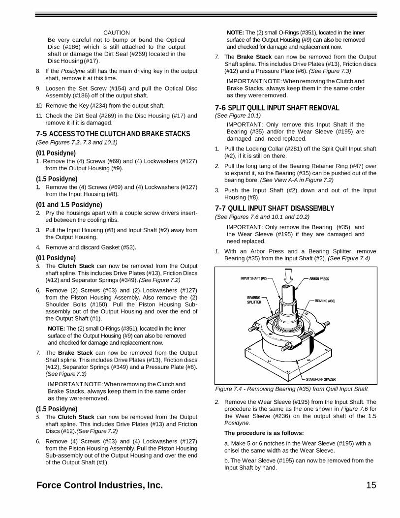
1. With an Arbor Press and a Bearing Splitter, remove

Bearing (#35) from the Input Shaft (#2). (See Figure 7.4)

Figure 7.4 - Removing Bearing (#35) from Quill Input Shaft

2. Remove the Wear Sleeve (#195) from the Input Shaft. The

procedure is the same as the one shown in Figure 7.6 for

the Wear Sleeve (#236) on the output shaft of the 1.5

Posidyne.

The procedure is as follows:

a. Make 5 or 6 notches in the Wear Sleeve (#195) with a

chisel the same width as the Wear Sleeve.

b. The Wear Sleeve (#195) can now be removed from the

Input Shaft by hand.

Force Control Industries, Inc. 15

7-8 MALE INPUT SHAFT DISASSEMBLY (See Figures 7.7 and 10.3)

IMPORTANT: Only remove Bearings (#35 and #38)

and the Wear Sleeve (#195) if they are damaged

and need replaced.

1. With an Arbor Press, Bearing Splitter and appropriate tool-

ing first remove Bearing (#38) and then Bearing (#35) from

the Input Shaft (#2). (See Figure 7.5.)

IMPORTANT: Only remove the Bearings (#26 and

#28) and the Wear Sleeve (#236) if they are dam-

aged and need replaced.

(1.5 Posidyne Only) 3. Remove the Wear Sleeve (#236) from the Output Shaft as

shown in Figure 7.6.

Figure 7.6 - Removing Wear Sleeve (#236) on 1.5 Posidyne

The procedure is as follows:

a. Make 5 or 6 notches in the Wear Sleeve (#236) with a chis-

el the same width as the Wear Sleeve.

b. The Wear Sleeve (#236) can now be removed from the

Output Shaft by hand.

(01 and 1.5 Posidyne) 4. Remove Bearing (#26) with a Bearing Puller. (See Figure 7.7)

Figure 7.5 - Removing Bearings from Male Input Shaft

2. Remove the Wear Sleeve (#195) from the Input Shaft. The

procedure is the same as the one shown in Figure 7.6 for

the other Wear Sleeve (#236) on the 1.5 Posidyne.

7-9 OUTPUT SHAFT REMOVAL AND DISASSEMBLY (See Figure 10.1)

1. Pull the long tang of the Bearing Retainer Ring (#44) over

to expand it, so the Bearing (#26) can be pushed out of the

bearing bore. (See View B-B in Figure 7.2)

2. Tap the Output Shaft (#1) out of the rear of the Output

Housing (#9) with a wooden mallet. Be careful not to

damage the lip of the Oil Seal (#32).

Figure 7.7 - Removing Bearing (#25)

16 Force Control Industries, Inc.

NOTE: On the 01 Posidyne the Mating Ring (#4) will

be pulled off with the Bearing (#26). There is also an

O-Ring (#80) behind the 01 Posidyne Mating Ring

(#4). Remove it from the Output Shaft (#1).

5. If the Pilot Bearing (#28) on the other end of the Output

Shaft (#1) needs replaced, take the Screw (#151) or (#76)

and the Bearing Retainer Washer (#182) off.

6. Pull the Bearing (#28) off the Output Shaft (#1) with a bear-

ing splitter.

7-10 REMOVING OIL SEALS (See Figure 10.1)

There is an Oil Seal (#31) in the Input Housing and an Oil Seal (#32) in the Output Housing. Only remove them if they are

damaged and need replaced.

1. Both Oil Seals can be removed with an Arbor Press.

7-11 PISTON HOUSING SUB-ASSEMBLY

DISASSEMBLY (See Figure 10.2)

1. Evenly back out the (4) Screws (#198) and with a screw

driver, pry the housings apart. Continue this procedure

until the spring pressure is relieved and the housings are

separated. Remove the (4) Screws (#198) and (4)

Lockwashers (#128).

CAUTION: This Piston Housing Sub-assembly is

under spring pressure and care must be taken to

avoid personal injury when removing these screws.

2. Remove and discard Gasket (#51).

3. Pull the Piston Sub-Assembly out of the Piston Housing

(#10) and remove the Springs (#36) from the Piston (#3).

NOTE: If all of the holes are not used it would be

helpful for you to make a free hand sketch of the

Spring Placement in the Piston. This will help you at

Reassembly.

4. Remove and inspect the O-Rings (#39 and #40) and the

Piston Seals (#42 and #43) from the Piston Housing (#10)

and the Piston Retainer (#11). (See Figure 10.2.)

IMPORTANT: Only remove the Thrust Plate (#5) and

the Bearing (#27) from the Piston if they are dam-

aged and need to be replaced.

5. Press out the Thrust Plate (#5) and the Bearing (#27) out of

the Piston (#3) with an Arbor Press.

6. With a Bearing Splitter, take the Bearing (#27) off of the

Thrust Plate (#5).

This completes the Disassembly Procedure.

Force Control Industries, Inc. 17

8-1 CLEANING AND INSPECTION

Section 8

CLEANING AND INSPECTION 4. Pay particular attention to Wear Sleeves (#195 and #236)

and shafts in the area of rotary seals. Check for nicks, Clean metal parts in a suitable solvent and dry in a stream of low pressure compressed air. The Clutch and Brake Drive

Plates (#13) can be cleaned in a solvent, but DO NOT clean

the Clutch and Brake Friction Discs (#12) in solvent. Use only

a clean, dry and lint-free rag to clean these Friction Discs.

(Solvent will damage the resilient paper-based friction materi-

al used on the Friction Discs). Keep the Drive Plates and

Friction Discs in the same order as they were removed. After

cleaning, inspect parts for cracks, distortion, scoring, nicks,

burrs or other damage would affect serviceability. Pay partic-

ular attention to the following:

1. Check the disc wear surfaces for scoring, galling or evi-

dence of uneven wear.

2. Check the clutch and brake plates for scoring or galling.

Make sure they are flat. If a perceptible ridge is worn in

any of the drive plates, replace all of the drive plates and

friction discs as a complete set.

3. Carefully check the piston and bore surfaces for nicks,

scratches, scoring or other damage which would affect

operation or cause leakage.

scratches which would cause leakage. Replace any dam-

aged parts.

5. It is not necessary to remove the ball bearings to check

their operation. Slowly rotate the free race of each bearing

by hand checking to see if it turns freely without rough or

flat spots.

8-2 REPAIR AND REPLACEMENT

A fine stone or crocus cloth may be used to remove minor sur-

face defects from parts so long as the operating or sealing

action of the part is not affected. The use of coarser abrasives

or other machining methods should not be attempted.

Otherwise, damaged parts should be replaced.

Replacement is recommended also for the following, as appli-

cable:

1. Replace all O-Rings, Liners, Gaskets and Oil Seals

removed during the course of disassembly.

2. Replace Clutch or Brake Discs and Drive Plates in com-

plete sets only.

18 Force Control Industries, Inc.

9-1 GENERAL REASSEMBLY INSTRUCTIONS

Section 9 REASSEMBLY

L. 7/8" Dia. Male Input Shaft - Outboard Bearing (#38)...................(Part No. 601-1.5-013)

1. Lubricate O-Rings and the lips of Oil Seals with the same

oil as used in the Drive Unit immediately before reassem-

bly and installation of any mating parts.

2. The installation of press fitted parts can be eased by heat-

ing the outside parts in an oven. Heat bearings to a maxi-

mum of 250° F.

CAUTION: Wear suitable gloves when handling

heated parts.

3. Apply Gasket Sealant (Permatex #3), or equivalent, only to

the flat gasket (#51) between the Piston Housing and the

Piston Retainer.

4. Use Cap Screw Adhesive (Loctite #271), or equivalent, to

all Cap Screws. Use sparingly and clean off any excess

with (Loctite #755) Adhesive Cleaner.

Basically the Reassembly Procedure is just a reverse order of

the Disassembly Procedure described in Section 7.

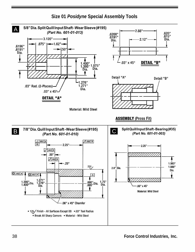
It requires special Assembly Tools to install the Bearings and

Wear Sleeves on the Input and Output Shafts. At the end of

Section 10 are machining drawings for each Assembly Tool if you prefer to make your own tools. Each Assembly Tool has

a Part Number and can be ordered from the Force Control

Factory.

They are as follows:

(Size 01 Posidyne) A. 5/8" Dia. Split Quill Input Shaft -

Wear Sleeve (#195)..........................(Part No. 601-01-013)

B. 7/8" Dia. Split Quill Input Shaft -

Wear Sleeve (#195)..........................(Part No. 601-01-010)

C. Split Quill Input Shaft -

Inboard Bearing (#35).......................(Part No. 601-01-003)

D. 7/8" Dia. Male Input Shaft -

Wear Sleeve (#195)..........................(Part No. 601-01-005)

E. 7/8" Dia. Male Input Shaft -

Outboard Bearing (#38)....................(Part No. 601-01-006)

F. 5/8" Dia. Output Shaft -

Mating Ring (#4) and Brg. (#26).......(Part No. 601-01-002)

G. 7/8" Dia. Output Shaft -

Mating Ring (#4) and Brg. (#26).......(Part No. 601-01-011)

H. Oil Seal Assembly Tool for -

Split Quill Input shaft.....................(Part No. 601-01-014 )

(Size 1.5 Posidyne)

I. 5/8” & 7/8” Split Quill Input Shaft -

Bearing (#35) & Wear Sleeve (#195)...(Part No. 601-1.5-017)

J. 1-1/8” Dia. Split Quill Input shaft-

Wear Sleeve (#195).........................(Part No. 601-1.5-020)

K. 7/8" Dia. Male Input Shaft -

Wear Sleeve (#195).........................(Part No. 601-1.5-009)

M. Quill Input Shaft -

Inboard Bearing (#35)......................(Part No. 601-1.5-003)

N. 7/8" Dia. Male Input Shaft -

Inboard Bearing (#35)......................(Part No. 601-1.5-012)

O. 5/8" Dia. Output Shaft -

Wear Sleeve (#236) & Brg. (#26)....(Part No. 601-1.5-014)

P. 7/8" Dia. Output Shaft -

Wear Sleeve (#236) & Brg. (#26)....(Part No. 601-1.5-002)

Q. 1-1/8" Dia. Output Shaft -

Wear Sleeve (#236) & Brg. (#26)....(Part No. 601-1.5-015)

R. 24 mm Dia. Output Shaft -

Wear Sleeve (#236) & Brg. (#26)....(Part No. 601-1.5-022)

S. Oil Seal Assembly Tool for -

Split Quill Input shaft....................(Part No. 601-1.5-023 )

9-2 REASSEMBLY OF THE PISTON

HOUSING SUB-ASSEMBLY (See Figure 10.2)

1. Apply Sealant (Loctite #620), or equivalent, to the I.D. of

Bearing (#27) and press it onto the Thrust Plate (#5) with

an arbor press. Make sure that the Bearing is well seat-

ed on the Thrust Plate shoulder.

IMPORTANT: Before applying (Loctite #620) to the

I.D. and O.D. of Bearing (#27), clean it well with

(Loctite #755) Cleaning Solvent.

2. Apply Sealant (Loctite #620) to the O.D. of Bearing (#27)

and press the Bearing and Thrust Plate into the Piston

(#3). Make sure that the Bearing is well seated into the

piston counterbore.

3. Install the O-Rings (#39 and #40) and the Teflon Liners

(#42 and #43) into the Piston Housing (#10) and Piston

Retainer (#11). See Figure 10.2 for correct placement of

the Liners and O-Rings.

4. Place the Piston Springs (#36) into the piston holes. White

grease may be used to hold the Springs in place during

reassembly. Refer to the sketch made at disassembly for

correct placement of the Piston Springs.

5. Insert the Piston Sub-Assembly into the Piston Housing (#10). Be careful not to damage the Teflon Liners in the

Piston Housing.

6. Apply Gasket Sealant (Permatex #3) to the mating sur-

faces on the Piston Housing (#10) and the Piston Retainer

(#11). Install Gasket (#51), using the Dowel Pins (#121) for

proper alignment.

7. Place the Piston Retainer (#11) over the Piston (#3). Be

careful not to damage the Teflon Liners in the Piston

Retainer. Attach with (4) Screws (#198) and (4)

Lockwashers (#128).

Force Control Industries, Inc. 19

IMPORTANT: Tighten these Screws in an even

manner to compress the Piston Springs correctly.

Torque to 12 Ft. Lbs.

9-3 OUTPUT SHAFT REASSEMBLY (See Figures 10.1)

(01 Posidyne) 1. With an arbor press and the proper Assembly Tool, press on

the Bearing (#26). Install the O-Ring (#80) onto the Output

Shaft shoulder. Then press the Mating Ring (#4) onto the

Output Shaft (#1) as shown in Figure 9.1.

(1.5 Posidyne) 1. With an arbor press and the proper Assembly Tool, press

the Bearing (#26) and then the Wear Sleeve (#236) onto the

Output Shaft (#1) as shown in Figure 9.1.

(01 Posidyne) 3. Install Screw (#151) and Washer (#182) into the end of the

Output Shaft (#1). Torque to 84 In. Lbs.

(1.5 Posidyne) 3. Install Screw (#76) and Washer (#182) into the end of the

Output Shaft (#1). Torque to 84 In. Lbs.

9-4 INPUT SHAFT REASSEMBLY (See Figures 10.1 and 10.2)

(Split Quill Input Shaft) 1. With an arbor press and the appropriate Assembly Tool,

install Inboard Bearing (#35) onto the Input Shaft (#2) as

shown in Figure 9.2.

Figure 9.2 - Installing Bearing (#35) on Quill Shaft

Figure 9.1 - Installing Bearing & Wear Sleeve/Mating Ring

(01 and 1.5 Posidyne) 2. Next press the Pilot Bearing (#28) onto the other end of the

Output Shaft (#1) with an arbor press and a flat plate

2. With an arbor press and the appropriate Assembly Tool,

install the Wear Sleeve (#195) onto the Input Shaft (#2) as

shown in Figure 9.3.

Figure 9.3 - Installing Wear Sleeve (#195) on Quill Shaft

20 Force Control Industries, Inc.

Figure 9.6 - Installing Wear Sleeve (#195) on Male Shaft

(Male Extended Input Shaft) 1. With an arbor press and the appropriate Assembly Tool,

install Inboard Bearing (#35) onto the Input Shaft (#2) as

shown in Figure 9.4.

Figure 9.4 - Installing Inboard Bearing (#35) on Male Shaft

2. With an arbor press and the appropriate Assembly Tool,

install Outboard Bearing (#38) onto the Input Shaft (#2) as

shown in Figure 9.5.

Figure 9.5 - Installing Outboard Bearing (#38) on Male Shaft

3. With an arbor press and the appropriate Assembly Tool,

install the Wear Sleeve (#195) onto the Male Input Shaft

(#2) as shown in Figure 9.6 .

9-5 INSTALLING OIL SEALS INTO

INPUT AND OUTPUT HOUSINGS (See Figure 10.1 )

1. Press the Oil Seal (#32) into the Output Housing (#9). Use

Sealant (Permatex #3) on the outside diameter of the Oil

Seal.

2. Press the Oil Seal (#31) into the Input Housing (#8). Use

Sealant (Permatex #3) on the outside diameter of the Oil

Seal.

9-6 INSTALLING OUTPUT SHAFT

INTO THE OUTPUT HOUSING (See Figure 10.1)

1. First lubricate the lip of the Oil Seal (#32) with vaseline or

equivalent.

2. Install the Bearing Retainer (#44) into the bearing bore.

3. Insert the Output Shaft Sub-Assembly into the Output

Housing, holding the long tang of the Bearing Retainer

(#44) over so the Bearing (#35) slides into the bearing bore

and the Retainer (#44) snaps into place.

CAUTION - Be very careful not to damage the lip of

the Oil Seal (#32) when inserting the Output Shaft

(#1).

9-7 MEASURING AND CONTROLLING

STACK HEIGHT To assure correct piston travel, the following steps must

be done when replacing the Clutch and Brake Stacks.

1. Based on the parts list, place the total number of Friction

Discs (#12) and Drive Plates (#13) in an arbor press as

shown in Figure 9.7. Clamp firmly and measure the stack

height.

2. Compare the measurement with the tabulated value given in

the following Stack Height Table and, if necessary, add one

or two Drive Plates to bring the stack within specified limits.

Force Control Industries, Inc. 21

Figure 9.7 - Measuring Stack Height

NOTE: Always add the extra Drive Plate to the stack

side away from the Piston. Add 1st. extra plate to the

Clutch Stack and 2nd. extra plate to the Brake Stack.

STACK HEIGHT TABLE

SIZE MIN MAX

01 with Clutch Only .365” .385”

01 with Clutch & Brake .730” .770”

01.5 with Clutch Only .546” .586”

01.5 with Clutch & Brake 1.092” 1.172”

9-8 INSTALLING BRAKE STACK (See Figures 9.8 and 10.1)

Place the Output Housing on a flat stable surface with the

keyed end of the Output Shaft in a down position.

1. First install the Brake Pressure Plate (#6) Align the holes

in the Brake Pressure Plate with the Pins (#122) in the

Output Housing.

2. Next place the Brake Stack onto the Output Shaft Spline,

starting with a Drive Plate (#13) and then a Friction Disc

(#12), ending with a Drive Plate (#13). Align the holes in

the Drive Plates with the Pins (#122) in the Output Housing

and align the internal teeth in the Friction Discs with the

teeth on the Output Shaft Spline.

NOTE: See Figure 10.8 for Brake Stack Configuration

with Vertical Installation. All Size 01 Posidynes have

(4) Separator Springs between each Drive Plate.

9-9 INSTALLING THE PISTON HOUSING ASSEMBLY (See Figure 9.8 and 10.1)

1. First place the (2) O-Rings (#351) into the (2) counterbores

in the Output Housing. (See Figure 9.8 for location of these

O-Rings.)

2. Attach the Piston Housing Assembly with (4) Screws (#63) and (4) Lockwashers (#127). (See Figure 9.8 for Torque

Requirements.)

9-10 INSTALLING CLUTCH STACK (See Figures 9.9 and 10.1)

1. Place the Clutch Stack onto the Output Shaft Spline, start-

ing with a Drive Plate (#13) and then a Friction Disc (#12),

ending with a Drive Plate (#13). Center the Drive Plates

(#13) on the Output Shaft as close as possible and align all

the holes up in the Drive Plates Align the internal teeth in

the Friction Discs (#12) with the teeth on the Output Shaft

Spline.

NOTE: See Figure 10.8 for Brake Stack Configuration

with Vertical Installation. All Size 01 Posidynes have

(4) Separator Springs between each Drive Plate.

Figure 9.9 - Installing Clutch Stack

22 Force Control Industries, Inc.

Figure 9.8 - Installing Brake Stack

9-11 INSTALLING INPUT SHAFT

AND INPUT HOUSING

(See Figure 10.1)

1. Lubricate the lip of the Oil Seal (#31) with vaseline or

equivalent.

2. Install the Bearing Retainer (#47) into the bearing retainer

groove in the bore of the Input Housing (#8).

Figure 9.10 - Installing Input Shaft into Input Housing

3. Place the appropriate Oil Seal Assembly Tool on the Input

Shaft so the Oil Seal (#31) will not get damaged as shown

in Figure 9.10.

4. Carefully insert the Input Shaft (#2) into the Input Housing

(#8) until the Bearing (#35) is completely seated in the

bearing bore and the Bearing Retainer (#47) snaps into

place into the bearing groove.

NOTE: The long tang of the Bearing Retainer (#47)

will have to be held over to expand it so the Bearing

(#35) will seat in the bearing bore and the Bearing

Retainer (#47) snaps into place.

CAUTION - Be very careful not to damage the lip of

the Oil Seal (#31) when inserting the Input shaft (#2).

5. Remove the Oil Seal Assembly Tool from the Input Shaft (#2).

6. Place the Gasket (#53) onto the Output Housing (#9) face.

Use the (2) Dowel Pins (#121) to align the gasket properly.

7. Make sure that the holes in the Clutch Stack Drive Plates

(#13) are all aligned with each other.

8. Place the Input Housing (#8) and Input Shaft (#2) down on the Output Housing (#9) and clutch stack. Make sure the

(4) Driver Pins (#184) in the Input Shaft (#2) are aligned

with the holes in the clutch stack. Tap the Input Housing

(#8) and the Input Shaft (#2) until they are firmly seated On

the Pilot Bearing (#28) and the Output Housing (#9) face.

9. Attach the housings together with (4) Screws (#69) and (4)

Lockwashers (#127). (See Figure 10.1 for Torque

Requirements.)

NOTE: The Unit will have to be turned over for the 01

Posidyne to insert the screws and lockwashers

10. Loosely install the Locking Collar (#281) on the Split Quill

Input shaft (#2). Do not tighten at this time. Make sure the

roll pin in the collar fits in the drilled indent in the shaft.

9-12 INSTALLING COOLING FAN ON INPUT SHAFT (See Figure 10.6)

(Quill Input Shaft) 1. Place the Tolerance Ring (#251) into the Fan (#25) and

press them both onto the Input Shaft (#2).

(Male Input Shaft) 1. First place the Tolerance Ring (#251) onto the Male Input

Shaft (#2), then press the Fan (#25) onto the Input Shaft

(#2) and Tolerance Ring (#251) as far as it will go.

9-13 FINAL REASSEMBLY

1. Replace any Pipe Plugs, Air Breather, Sight Gauge, etc.

removed during disassembly.

2. Fill with Automatic Transmission Fluid as specified in Section 4 LUBRICATION.

This completes the Reassembly Procedure for the 01 and 1.5

Posidyne Clutch/Brake Unit. Before proceeding any further an

Operational Check of the Clutch and Brake movement should

be made. Apply 60 to 80 PSI to the Clutch and Brake ports, as indicated in Section 5 - OPERATIONAL CHECKS, and

observe the Piston Movement through the inspection port.

3. Replace any optional equipment removed during disas-

sembly such as:

a. 8-1/2" AK C-Face Flanges (See Figure 10.3)

b. Manifold Mounted Control Valve (See Figure 10.4)

c. Optical Encoder Assembly (See Figure 10.4)

d. Fan Cooling (See Figure 10.5 and Section 9-12 above.)

e. Foot Mounting (See Figure 10.6)

f. Vertical Installation Parts(See Figure 10.8)

9-14 REMOUNTING THE DRIVE

UNIT TO THE C-FACE MOTOR (See Figure 3.1 in Section 3 INSTALLATION)

Refer to 3-2 Mounting the Drive Unit for correct Mounting

Spool Alignment procedure.

After Reassembly is completed completely check the

operation of your Posidyne Clutch/Brake as specified in

Section 5 - OPERATIONAL CHECKS.

Force Control Industries, Inc. 23

10-1 GENERAL INFORMATION

Section 10

ORDERING REPAIR PARTS RETURN TO :

This section illustrates, lists and describes all available repair

parts for the Force Control 01 and 1.5 Posidyne Clutch/Brake

Drive Units. Parts are identified on the exploded views with

Part Reference Numbers. These Numbers correspond to the

Part Reference Number given in the Parts List. The Part Name

and Quantity is also given in the Parts List. This Part

Reference Number, Part Name and Quantity should be used

when ordering parts.

The Exploded View Drawings are as follows:

Figure 10.1 - 01 and 1.5 Posidyne Clutch Brake Unit.

Figure 10.2 - Piston Housing and Retainer

Sub-Assembly.

Figure 10.3 - Optional Extended Male Input Shaft.

Optional 8-1/2" AK C-Face Adapters.

Figure 10.4 - Optional Manifold Mounted Control Valves.

Optional Optical Encoder Assembly.

Figure 10.5 - Optional Fan Cooling.

Figure 10.6 - Optional Foot Mounting.

Figure 10.7 - Clutch/Brake Stacks (Vertical Mounting)

Figure 10.8 - Vertical Installation Kits.

10-2 DRIVE MOTORS

The motors used with these Drive Units are standard and may

be repaired or replaced by any qualified motor rebuild facility

or supplier.

10-3 FACTORY REBUILD SERVICE

Reconditioning service is offered by Force Control Industries

at the factory. Unless major parts (such as housings and pis-

tons, etc.) are damaged, the cost of complete factory rebuild

will be 50% the cost of a new unit. Before returning a unit for

this service, however, be sure to first contact the Force Control

Industries Service Sales Department for authorization and

shipping instructions. Force Control Industries cannot be

responsible for units returned to the factory without prior notice

and authorization.

Care must be given to the packing of return drives. Always

protect mounting feet by attaching to a skid. Shipment-dam-

aged drives always delay repairs. It is usually impossible to

recover damage costs from the carrier. When possible

describe the problem experienced on your shipping papers.

Force Control Industries, Inc.

3660 Dixie Highway

Fairfield, Ohio 45014

Telephone: 513-868-0900

Fax No.: 513-868-2105

E-Mail: [email protected]

10-4 ORDERING REPLACEMENT PARTS

When ordering replacement parts, please specify all of the fol-

lowing information:

1. Drive Model Number (on the name plate)

2. Drive Serial Number (on the name plate)

3. Part Reference Number (from the parts list or

exploded view drawing.)

4. Part Name (from the parts list)

5. Quantity (from the parts list)

6. Complete Shipping Information

Failure to include information for items 1 thru 6 will only delay

your parts order. Unless another method is specified for item

6, parts less than 150 pounds will be shipped United Parcel

Service, parts over 150 pounds will be shipped Motor Freight.

Air freight and other transportation services are available but

only if specified on your order.

10-5 NAME PLATE and MODEL NUMBERS

The Name Plate shown is located on the Input Housing.

24 Force Control Industries, Inc.

Fairfield, Ohio

513-868-0900 ®

Clutch/Br

Model No.

Serial No. Use Mobil® ATF 210

=

01 and 1.5 Posidyne Clutch/Brake

MODEL NUMBERS

1 2 3 4 5 6 7 8 9 10

SIZE (1,2)

= 01

= 1.5

INPUT (3)

1 = 7/8” FU Extended Shaft. (With Mounting Foot)

OUTPUT (5)

1 = 7/8” U Male Shaft (With Mntg. Foot)

ENGINEERING REVISION (9)

By Force Control Industries, Inc.

STACK COMBINATION (8)

Q = Green with ATF-210

W = Green with Multi-Purpose ATF

2 = 4-1/2” FAK, 5/8” FU with Clamped Split Quill Input Shaft. (56C Frame)

= 4-1/2” FAK, 5/8” U. (56C Frame)

3 = 4-1/2” FAK, 7/8” FU with Clamped Split Quill Input Shaft.

= 4-1/2” FAK, 7/8” U. (143TC / 145TC Frame)

PORTING/VALVE LOCATION (8) (Viewing Input Shaft) See Below

(143TC / 145TC Frame)

= 8-1/2” FAK, 1-1/8” FU with Clamped Split Quill Input Shaft (182TC / 184TC Frame)

A = 4-1/2” FAK, 5/8” FU with Clamped Split Quill Input Shaft and Foot Mounting. (56C Frame)

B = 4-1/2” FAK, 7/8” FU with Clamped Split Quill Input Shaft and Foot Mounting (143TC/145TC Frame)

C = 8-1/2” FAK, 1-1/8” FU with Clamped

C-Face

= 8-1/2” FAK, 1-1/8” U. (1.5 Only) (182TC / 184TC Frame)

A = Optical Encoder*

4-1/2” AK, 5/8” U.

C = Optical Encoder*

4-1/2” AK, 7/8” U.

D = Optical Encoder*

7/8” U and Foot Mounting

E = Optical Encoder* 8-1/2” AK, 1-1/8” U

C-Face

C-Face

T = Top

R = Right

= Bottom

= Left

Split Quill Input Shaft and Foot Mounting. (182TC / 184TC Frame)

LOGIC (4)

S = Std. - Air Set Clutch/Light Spring Set Brake,with Air Assist.

A = A - Air Set Clutch/Med. Spring Set Brake.

B = B - Air Set Clutch/Heavy Spring Set Brake.

C = C - Air Set Clutch/No Brake.

D = SA - Air Set Clutch/Med. Spring

Set Brake with Air Assist.

P = Air Set Clutch/Brake without Springs.

* Machined to accept an Encoder. See Section 14 for Ordering Encoder.

MOUNTING POSITION (6)

H = Horizontal.

D = VID - Vertical, Input Down.

U = VIU - Vertical, Input Up.

L = Wall on Left Viewing Input Shaft.

R = Wall on Right Viewing Input Shaft.

COOLING (7)

1 = Basic (Radiant)

5 = Fan Cooled.

6 = Basic, (Manifold Mntd. Valve)

7 = Fan Cooled, (Manifold Mntd. Valve)

Force Control Industries, Inc. 25

B

L

3

2

4

PORTING/VALVE LOCATION (Viewing Input Shaft)

ASSEMBLY OPTIONS

Location Std. C-Face Foot

Mntd.

Piggy

Back

T X X X ---

R X X X X

B X X --- X

L X X X X

0 1

1 5

01 and 1.5 Posidyne CLUTCH/BRAKE UNIT (With Split Clamp Quill Input Shaft)

(Figure 10.1)

REF. No. PART NAME QTY.

REF. No.

PART NAME QTY.

1 Output Shaft ................................................. 1 73 Reducer Bushing .......................................... 1 2

*4

Quill Input Shaft ............................................

Mating Ring (01 Posidyne only) ..................

1

1 74

76

Pipe Plug, 1/8" NPT......................................

Soc. Hd. Cap Screw (1.5 Posidyne only) .....

2

1 *6 Brake Pressure Plate (Not on "C" Logic.)..... 1 *80 O-Ring (01 Posidyne only) ........................... 1 8 Input Housing ............................................... 1 121 Dowel Pin, 1/4" x 1" ...................................... 2 9 Output Housing............................................. 1 122 Dowel Pin, Brake (Not used on "C" Logic.) .. 4

*12 Friction Disc (See note below) 127 Lockwasher

01 - "A", "B", "S", and "SA" Logic.............. 4 01 Posidyne .............................................. 4

*13

*26

*28

*31

*32

*35

44

*45

*46

47

*53

63

69

72

01 -"C" Logic .............................................

1.5 - "A", "B", "S", and "SA" Logic.............

1.5 -"C" Logic ............................................

Drive Plate (See note below)

01 -"A", "B", "S", and "SA" Logic...............

01 -"C" Logic .............................................

1.5 -"A", "B", "S", and "SA" Logic..............

1.5 -"C" Logic ............................................

Bearing, Output Shaft ...................................

Pilot Bearing .................................................

Oil Seal, Input Shaft .....................................

Oil Seal, Output Shaft...................................

Bearing, Input Shaft......................................

Bearing Retainer...........................................

Air Breather ..................................................

Sight Gauge..................................................

Bearing Retainer...........................................

Main Gasket..................................................

Soc. Hd. Cap Screw

01 Posidyne ..............................................

1.5 Posidyne .............................................

Soc. Hd. Cap Screw......................................

Pipe Plug, 1/2" NPT......................................

2

6

3

6

3

8

4

1

1

1

1

1

1

1

1

1

1

2

4

4

2

128

150

151

154

181

182

184

*195

208

218

221

*236

241

281

303

305

346

*349

*351

367

1.5 Posidyne .............................................

Lockwasher (01 Posidyne Only)...................

Shoulder Screw (01 Posidyne Only) ............

Soc. Hd. Cap Screw (01 Posidyne Only)......

Soc. Set Screw, Cone Point..........................

Key, Output Shaft..........................................

Washer, Bearing Retainer ............................

Dowel Pin, Clutch .........................................

Wear Sleeve .................................................

Plug, Input Shaft ...........................................

Roll Pin (01 Posidyne Only) .........................

Spool, Mounting (Std. 4-1/2" AK Input) ........

Wear Sleeve (1.5 Posidyne only) .................

Heli-coil Insert...............................................

Locking Collar ...............................................

Roll Pin (1.5 Posidyne Only) ........................

Hex. Hd. Cap Screw .....................................

Heli-coil Insert...............................................

Separator Springs (01 Posidyne Only)

"A", "B", "S", and "SA" Logic ........................

"C" Logic ...................................................

O-Ring ..........................................................

Lockwasher, 3/8" ..........................................

8

4

2

1

4

1

1

4

1

1

1

4

1

4

1

1

4

4

16

8

2

4

* - Indicates parts in Overhaul Kit.

NOTE: See Figure 10.6 for Clutch/Brake Stacks with Vertical Installation.

26 Force Control Industries, Inc.

01 and 1.5 Posidyne CLUTCH/BRAKE UNIT (With Split Clamp Quill Input Shaft)

Figure 10.1 - 01 and 1.5 Posidyne Clutch/Brake Unit With Split Quill Input Shaft

Force Control Industries, Inc. 27

PISTON HOUSING & RETAINER SUB-ASSEMBLY

(Figure 10.2)

REF. No. PART NAME QTY.

REF. No.

PART NAME QTY.

3

5

10

11

* 27

* 36

* 39

Piston............................................................

Clutch Thrust Plate .......................................

Piston Housing .............................................

Piston Retainer .............................................

Bearing .........................................................

Compression Spring

01 Posidyne - "S" and ""C" Logic.............

01 Posidyne - "A" and "SA" Logic............

01 Posidyne - "B" Logic ...........................

1.5 Posidyne - "S" and ""C" Logic.............

1.5 Posidyne - "A" and "SA" Logic............

1.5 Posidyne - "B" Logic ...........................

O-Ring

1

1

1

1

1

6

14

28

6

18

36

* 40

* 42

* 43

* 51

121

128

152

198

O-Ring

01 Posidyne .............................................

1.5 Posidyne .............................................

Teflon Liner

"S" and "SA" Logic ....................................

"A", "B" and "C" Logic ...............................

Teflon Liner ...................................................

Gasket ..........................................................

Dowel Pin (01 Posidyne Only) ......................

Lockwasher, 5/16" ........................................

Cinch Nut ......................................................

Soc. Hd. Cap Screw......................................

2

1

2

1

1

1

4

4

4

4

"S" and "SA" Logic .................................... 2

"A", "B" and "C" Logic ............................... 1

* - Indicates parts in Overhaul Kit.

28 Force Control Industries, Inc.

PISTON HOUSING & RETAINER SUB-ASSEMBLY

Figure 10.2 - Piston Housing & Retainer Sub-Assembly

Force Control Industries, Inc. 29

OPTIONAL EXTENDED MALE INPUT SHAFT

OPTIONAL 8-1/2” AK C-FACE ADAPTER (1.5 Posidyne Only)

(Figure 10.3)

REF. No. PART NAME QTY.

REF. No.

PART NAME QTY.

2

*35

*38

*47

154

180

184

*195

200

Output Shaft .................................................

Bearing .........................................................

Bearing .........................................................

Bearing Retainer...........................................

Set Screw, Cone Point..................................

Key................................................................

Dowel Pin, Clutch .........................................

Wear Sleeve .................................................

Input C-Face Adapter, 8-1/2" AK ..................

1

1

1

1

4

1

4

1

1

201

203

204

205

239

305

367

392

Soc. Hd. Cap Screw......................................

Output C-Face Adapter, 8-1/2" AK ...............

Soc. Hd. Cap Screw......................................

Lockwasher...................................................

Mounting Spool.............................................

Hex. Hd. Cap Screw .....................................

Lockwasher...................................................

Heli-Coil Insert ..............................................

4

1

4

4

4

4

4

4

* - Indicates parts in Overhaul Kit.

30 Force Control Industries, Inc.

OPTIONAL EXTENDED MALE INPUT SHAFT

OPTIONAL 8-1/2” AK C-FACE ADAPTER (1.5 Posidyne Only)

Figure 10.3 - Optional Extended Male Input Shaft and 8-1/2” AK C-Face Adapter

Force Control Industries, Inc. 31

OPTIONAL MANIFOLD MOUNTED CONTROL VALVES

OPTIONAL OPTICAL ENCODER ASSEMBLY (Figure 10.4)

REF. No. PART NAME QTY.

REF. No.

PART NAME QTY.

17

18

*19

76

77

154

186

225

234

257

259

260

269

355

356

368

Encoder Housing ..........................................

Upper Enclosure ...........................................

Gasket ..........................................................

Hex Hd. Screw ..............................................

Soc. Hd. Screw .............................................

Set Screw .....................................................

Optical Disc Assembly ..................................

But.Hd. Screw ...............................................

Key................................................................

Lockwasher...................................................

Cable ............................................................

Cable Grommet ............................................

Dirt Seal........................................................

Circuit Board .................................................

Jumper ..........................................................

Cable Connector...........................................

1

1

2

4

2

1

1

4

1

4

1

1

1

1

1

1

372

373

700

701

725

727

737

738

767

*807

*808

810

811

Top Cover .....................................................

Insulator ........................................................

Manifold Mounted Control Valve ...................

Manifold Spacer............................................

Cap Screw ....................................................

Cap Screw ....................................................

Lockwasher...................................................

Seal...............................................................

Pressure Gauge

1-PC-3/8" Valve .........................................

2-PC-3/8" Valve .........................................

Manifold Gasket ............................................

O-Ring ..........................................................

Locating Tube ...............................................

Fastener........................................................

1

1

1

1

2

4

2

2

1

2

1

2

1

2

* - Indicates parts in Overhaul Kit.

32 Force Control Industries, Inc.

OPTIONAL MANIFOLD MOUNTED CONTROL VALVE

OPTIONAL OPTICAL ENCODER ASSEMBLY

Figure 10.4 - Optional Manifold Mounted Control Valve and Optical Encoder Assembly

Force Control Industries, Inc. 33

OPTIONAL FAN COOLING

(Figure 10.5)

REF. No. PART NAME QTY.

REF. No.

PART NAME QTY.

24

25

66

154

Fan Shroud ...................................................

Cooling Fan ..................................................

Hex. Hd. Cap Screw .....................................

Cone Point Set Screw...................................

1

1

4

4

239

*251

367

Mounting Spool, Short..................................

Tolerance Ring..............................................

Lockwasher...................................................

4

1

4

*- Indicates parts in Overhaul Kit.

Figure 10.5 - Optional Fan Cooling

OPTIONAL FOOT MOUNTING (Figure 10.6)

REF. No. PART NAME QTY.

REF. No.

PART NAME QTY.

66 Hex. Hd. Cap Screw ..................................... 4 265 Lockwasher................................................... 2

154 Cone Point Set Screw................................... 4 367 Lockwasher

165 Foot Mounting Bracket.................................. 2 Foot Mounting Only ................................... 2

221 Mounting Spool, Long (C-Face Motor) ........ 2 Foot Mounting, C-Face Motor ................... 4

239 Mounting Spool, Short Fan Cooled with Foot Mounting ................ 4 Foot Mounting Only ................................... 2 392 Hex. Nut

Fan Cooled with Foot Mounting ................ 4 Foot Mounting Only ................................... 2

263 Hex. Hd. Cap Screw ..................................... 2 Fan Cooled with Foot Mounting ................ 4

264 Flat Washer (Without Fan Cooling) .............. 2

34 Force Control Industries, Inc.

OPTIONAL FOOT MOUNTING (With Extended Male Input Shaft Only)

OPTIONAL FOOT MOUNTING (With C-Face Motor)

Figure 10.6 - Optional Foot Mounting

Force Control Industries, Inc. 35

VERTICAL INSTALLATION KITS

(Figures 10.7 & 10.8)

REF. No.

PART NAME

QTY. REF. No.

PART NAME QTY.

*6 Brake Pressure Plate (Not on "C" Logic)...... 1 90 Reducer Bushing (01 Posidyne Only) ........... 1

*12 Friction Disc 92 Sq. Hd. Mag. Pipe Plug................................. 1 01 - "A", "B", "S" and "SA" Logic ............... 4 101 Reducer Bushing (01 Posidyne Only) ........... 1 01 - "C" Logic ............................................ 2 136 90° Elbow...................................................... 1 1.5 - "A", "B", "S" and "SA" Logic .............. 6 144 Hose.............................................................. 1 1.5 - "C" Logic ........................................... 3 145 Hose Fitting................................................... 1

*13 Drive Plate, Standard 146 90° Swivel Hose Adapter .............................. 1 01 - "A", "B", "S" and "SA" Logic ............... 6 147 Hose Fitting................................................... 1 01 - "C" Logic ............................................ 3 *229 Separator Spring (1.5 Posidyne)

1.5 - "A", "B", "S" and "SA" Logic .............. 2 "A", "B", "S" and "SA" Logic ...................... 24 1.5 - "C" Logic ........................................... 1 "C" Logic.................................................... 12

20 Accumulator .................................................. 1 *323 Drive Plate, with rivets (1.5 Posidyne)

*45 Breather ........................................................ 1 "A", "B", "S" and "SA" Logic ..................... 6

*46 Sight Gauge .................................................. 1 "C" Logic................................................... 3 73 Reducer Bushing .......................................... 1 *349 Separator Spring (01 Posidyne)

74

81

Pipe Plug ......................................................

Pipe Nipple ...................................................

1

1

"A", "B", "S" and "SA" Logic ..................... "C" Logic...................................................

16 8

82 Pipe Nipple ................................................... 1

* - Indicates parts in Overhaul Kit.

Figure 10.7 - Clutch and Brake Stacks (Vertical Installation)

36

Force Control Industries, Inc.

VERTICAL INSTALLATION KITS (VERTICAL - INPUT UP)

(VERTICAL - INPUT DOWN)

Figure 10.8 - Vertical Installation Kits

Force Control Industries, Inc. 37

Size 01 Posidyne Special Assembly Tools

38 Force Control Industries, Inc.

A

C

Size 01 Posidyne Special Assembly Tools

D 7/8” Dia. Male Input Shaft - Wear Sleeve (#195)

(Part No. 601-01-005) E 7/8” Dia. Male Input Shaft - Bearing (#38)

(Part No. 601-01-006)

F 5/8” Dia. Output Shaft - Bearing (#26) and

Mating Ring (#4) (Part No. 601-01-002) G 7/8” Dia. Output Shaft - Bearing (#26) and

Mating Ring (#4) (Part No. 601-01-011)

OIL SEAL ASSEMBLY TOOL - SPLIT QUILL

INPUT SHAFT ( Part No. 601-01-014- )

Force Control Industries, Inc. 39

H

Size 1.5 Posidyne Special Assembly Tools

I 5/8” - 7/8” Dia. Split Quill Input Shaft - Wear

Sleeve (#195) (Part No. 601-1.5-017) J 1-1/8” Dia. Split Quill - Wear Sleeve (#195)

(Part No. 601-1.5-020)

K 7/8” Dia. Male Input Shaft - Wear Sleeve (#195)

(Part No. 601-1.5-009) L 7/8” Dia. Male Input Shaft - Bearing (#38)

(Part No. 601-1.5-013)

M Quill Input Shaft - Bearing (#35)

(Part No. 601-1.5-003) N Male Input Shaft - Bearing (#35)

(Part No. 601-1.5-012)

40 Force Control Industries, Inc.

Size 1.5 Posidyne Special Assembly Tools

Oil Seal Assembly Tool - Split Quill

Input Shaft (Part No. 601-1.5-023- )

Force Control Industries, Inc. 41

O

P

R

S

Manual Revision History

REVISION

NUMBER REVISION DATE

(Mo./Yr.)

REVISION DESCRIPTION

502-01/1.5-003-02

06/10

Converted to PC format. Clarified overhaul kits.

502-01/1.5-003-03

11/17

Converted to Word format. Removed thrust plate and terms major and minor from overhaul kits.

Force Control Industries, Inc. 42

FORCE CONTROL INDUSTRIES, INC.

Worldwide Leader in Oil Shear Technology.

Providing today’s industries

with Oil Shear Clutch and

Brake Drives that delivers:

Flexibility • Efficiency

Endurance • Performance

Dependability

“Built to Last - Guaranteed to Perform”

FORCE CONTROL INDUSTRIES, INC.

MAIN OFFICE

3660 Dixie Highway

Fairfield, Ohio 45014

Tel: (513) 868-0900

Fax: (513) 868-2105

E-Mail: [email protected]

Web Site: www.forcecontrol.com

Force Control Industries, Inc. 43


Recommended