VOLUME I / EXPLORATION, PRODUCTION AND TRANSPORT 5.3.1 Introduction This chapter will cover all surface facilities (referred to as such to distinguish them from production wells) used to gather reservoir fluids, separate crude oil from other phases, and ensure sufficient treatment of the latter to render it transportable. According to this scheme, the surface facilities used for separation and treatment, known as treatment plants, are those comprised between the production wellhead (excluded) and the crude oil storage facilities (included). Finally, the surface plants used for secondary recovery projects will be considered. This discussion will also cover the equipment needed to inject water and gas, and their pumping and compression systems, up to the head of the injection well (excluded). For a description of chemical and physical properties of the reservoir fluid produced and carried to the surface by production wells, see Chapter 4.2. Except in some unusual cases, the fluid produced by an oil field reaches the production well head as a combined result of two or three phases. The main liquid phase is the crude oil itself, saturated in dissolved light hydrocarbons under wellhead conditions (delivery pressure and temperature). The second phase of the well head fluid is associated gas, which is in thermodynamic equilibrium with the liquid phase described above. Consequently, the gas phase associated with the crude oil is saturated in heavy hydrocarbons (hydrocarbon dew point) at the delivery pressure and temperature mentioned above. During the production of a field, the wellhead fluid also frequently consists of a third phase: free water. This phase, as well, is in equilibrium with the two phases described above, and the associated gas is therefore saturated in water (water dew point). Depending on its origin, the free water phase may consist of formation water (i.e. coming directly from the productive formation where it is already present as a free phase), or supersaturation water. The main property of formation water is its high salt content, in some cases up to 340 g/l of TDS (Total Dissolved Solids). When salinity is very high, this is mainly due to chlorides, though carbonates, bicarbonates and sulphates may also be present in quantities close to their saturation levels. Given these properties, formation water represents one of the main contaminants of crude oil production, since its presence as a dispersed phase within the oil gives the latter a salinity that causes problems in field treatment and later in refining processes. In other words, salinity must be reduced with suitable treatments (see Section 5.3.4) to ensure that the crude oil can be transported and commercialized. When an oil field comes into production, formation water is not present, except in unusual cases. In later years, and especially during the advanced stage of reservoir exploitation, the percentage of water in terms of volume produced by the wells (water cut) may become extremely high – so high that it is not unusual to have production wells with a water cut above 50%. It is easy to perceive that limited values for water cut correspond to a dispersed water phase in a dispersing crude oil phase. On the other hand, when values are high, formation water becomes the dispersing phase and oil the dispersed phase. The properties of these emulsions are discussed in Section 5.3.4. The free water phase may also be devoid of salinity. This occurs when, instead of coming directly from the productive formation, free water forms due to the oversaturation of either the liquid hydrocarbon phase or the associated gas phase, or both. Oversaturation is caused by the cooling that the fluid delivered by the reservoir undergoes along the well string. The solubility of water, both in the oil phase 643 5.3 Treatment plants for oil production
Transcript
VOLUME I / EXPLORATION, PRODUCTION AND TRANSPORT
5.3.1 Introduction
This chapter will cover all surface facilities (referredto as such to distinguish them from production wells)used to gather reservoir fluids, separate crude oil fromother phases, and ensure sufficient treatment of thelatter to render it transportable.
According to this scheme, the surface facilities usedfor separation and treatment, known as treatment plants,are those comprised between the production wellhead(excluded) and the crude oil storage facilities (included).Finally, the surface plants used for secondary recoveryprojects will be considered. This discussion will alsocover the equipment needed to inject water and gas, andtheir pumping and compression systems, up to the headof the injection well (excluded). For a description ofchemical and physical properties of the reservoir fluidproduced and carried to the surface by production wells,see Chapter 4.2.
Except in some unusual cases, the fluid producedby an oil field reaches the production well head as acombined result of two or three phases. The mainliquid phase is the crude oil itself, saturated indissolved light hydrocarbons under wellheadconditions (delivery pressure and temperature). Thesecond phase of the well head fluid is associated gas,which is in thermodynamic equilibrium with the liquidphase described above. Consequently, the gas phaseassociated with the crude oil is saturated in heavyhydrocarbons (hydrocarbon dew point) at the deliverypressure and temperature mentioned above. During theproduction of a field, the wellhead fluid alsofrequently consists of a third phase: free water. Thisphase, as well, is in equilibrium with the two phasesdescribed above, and the associated gas is thereforesaturated in water (water dew point). Depending on itsorigin, the free water phase may consist of formationwater (i.e. coming directly from the productive
formation where it is already present as a free phase),or supersaturation water.
The main property of formation water is its highsalt content, in some cases up to 340 g/l of TDS (TotalDissolved Solids). When salinity is very high, this ismainly due to chlorides, though carbonates,bicarbonates and sulphates may also be present inquantities close to their saturation levels. Given theseproperties, formation water represents one of the maincontaminants of crude oil production, since itspresence as a dispersed phase within the oil gives thelatter a salinity that causes problems in field treatmentand later in refining processes. In other words, salinitymust be reduced with suitable treatments (see Section5.3.4) to ensure that the crude oil can be transportedand commercialized.
When an oil field comes into production,formation water is not present, except in unusualcases. In later years, and especially during theadvanced stage of reservoir exploitation, thepercentage of water in terms of volume produced bythe wells (water cut) may become extremely high – sohigh that it is not unusual to have production wellswith a water cut above 50%.
It is easy to perceive that limited values for water cutcorrespond to a dispersed water phase in a dispersingcrude oil phase. On the other hand, when values arehigh, formation water becomes the dispersing phase andoil the dispersed phase. The properties of theseemulsions are discussed in Section 5.3.4.
The free water phase may also be devoid ofsalinity. This occurs when, instead of coming directlyfrom the productive formation, free water forms due tothe oversaturation of either the liquid hydrocarbonphase or the associated gas phase, or both.Oversaturation is caused by the cooling that the fluiddelivered by the reservoir undergoes along the wellstring. The solubility of water, both in the oil phase
643
5.3
Treatment plants for oil production
and in the associated gas phase, drops markedly astemperature decreases (Fig. 1). The water separatedfrom the two hydrocarbon phases (liquid and gaseous)is thus devoid of salinity.
Both formation water and oversaturation watercontain suspended solids. Where present, the freewater phase tends to stratify, since it is heavier than thecrude oil phase; as a result, most of the solidimpurities dragged from the reservoir or produced dueto corrosion in the pipelines tend to accumulate in thewater phase. When referring to a crude oil, it iscommon practice to consider residual water contentand sediments as a single parameter: BS&W (BottomSediments and Water).
The two hydrocarbon phases (liquid and vapour)enter the production facilities as a mixture. Frequently,these hydrocarbons are found in a single phase withinthe reservoir from which they are produced; in otherwords, the pressure of the productive formation iseither equal to or higher than the bubble point of themixture concerned at formation temperature. Thiscircumstance occurs very frequently in oil reservoirsunder original conditions. Often, during the depletionof the reservoir, pressure tends to drop rapidly; thisleads to the creation of two separate phases within theproductive formation itself.
The facts outlined above are intended to highlightthe common origin of the two phases, and thus theirshared chemical nature. It is common practice to studyand characterize an oil field on the basis of thechemical composition of the reservoir fluid; this isreferred to as ‘recombination’, since it is obtained byrecombining the two phases, produced and sampledseparately, according to their original proportions.
The recombination of a petroleum reservoir, and ofan oilfield in particular, is a mixture of hydrocarbonswith a variable light and heavy hydrocarbon content.In light hydrocarbons methane predominates, whileethane, propane and butane are also present, though inmore modest and decreasing quantities. Given theirvolatility, these components are predominantly presentin the vapour phase as they enter production facilities.Heavy hydrocarbons present enormous variability.Hydrocarbons of varying molecular weight exist, fromthat of pentanes (with a value of 72.17) up to valuesthat are an order of magnitude higher.
As already mentioned in Chapter 1.1, oil reservoirscontain almost the entire range of saturated andunsaturated hydrocarbons, paraffins, naphthenes andaromatics (olefins, however, are absent). As far asparaffins, or aliphatics, are concerned, both linear andbranched chain types are present. The physicalproperties (the density and viscosity of the variousfractions of a crude) depend on the variable presenceof the components mentioned. Therefore, it is common
practice to characterize crudes according to theirpredominant paraffin, naphthene or aromatic content.This characterization, like specific density (or APIgravity), is of considerable practical interest in therefining industry and for the commercialization ofcrude oil. It is of minor relevance, however, in theevaluations needed to determine the type of gatheringand treatment procedures used for crude oil.
In the past, numerous attempts were made tocorrelate the chemical-physical properties of crudeoils and their cuts in a simple way. The mostinteresting, though rarely used in production activities,is the UOP (Universal Oil Product) characterizationfactor. This factor, indicated with the symbol K, relatesthe mean boiling point at atmospheric pressure of apetroleum cut to its relative density,K�[(460�tf)�d ](1/3), where tf expresses temperaturein degrees Fahrenheit, and d is the specific density ofcrude cut relevant to water at 60°C. For many crudes,this factor remains relatively constant for most cuts,with the exception of both very light and especiallyvery heavy cuts. The UOP factor can also be directlycorrelated with the degree of hydrocarbon saturationof which the crude is composed. The lower the valueof K, the lower the hydrogen/carbon ratio, and vice
Fig. 1. Solubility of water in liquid hydrocarbons (GPSA, Gas Processors Suppliers Association).
versa. Consequently, crudes with a high aromaticcontent have a relatively low value for K (10-11),whereas those with a paraffinic base have considerablyhigher values (12-12.5).
A reservoir fluid, and the crude oil deriving fromit, do not only contain hydrocarbons. These fluids alsocontain other elements, such as nitrogen, mainly in theform of N2, but also nitrogen compounds, sulphur inthe form of various sulphur compounds such ashydrogen sulphide (H2S), mercaptans, ranging fromthe lighter methyl and ethyl mercaptans present inlight cuts (benzene) to heavier types, as well as ternaryaromatic sulphur compounds. Oxygen is also present,mainly as carbon dioxide or water. In the reservoirfluid dissolved oxygen, O2 is not present. After storageat atmospheric pressure, the stabilized crude maycontain dissolved oxygen, since it has come intocontact with air during the storage process. Thepresence of oxygen accentuates chemical reactions,with the partial oxidation of high-boiling and highlyunsaturated compounds. Finally, a crude oil maycontain helium (He), elementary mercury or itscompounds, such as mercury sulphide (HgS) andothers; other heavy metals such as chrome, vanadiumand their salts may also be present in the reservoirfluid.
Sulphur compounds have a significant impact onoil refining treatment, and an extremely negativeinfluence on the commercialization of the crude. Insimple terms: total sulphur contents above 1.5% inweight in a crude oil considerably penalize the salesprice. By contrast, crudes with a low sulphur contenthave a higher price. In the field production andtreatment of oil, it is not possible to alter the totalsulphur content significantly; however, it is offundamental importance to reduce both the H2S andmercaptan content. The first of these compounds is alethal gas even at very low concentrations; it isextremely dangerous since, being heavier than air, ittends to stratify in the environment. The reduction ofmercaptans is necessary only for those which arevolatile and more aggressive (methyl and ethylmercaptans); this reduction must be carried out duringthe treatment phases if their content exceeds allowedvalues.
5.3.2 Characterization of oils
The development and exploitation phase of an oil fieldrequires an extensive knowledge of the chemicalphysical properties of the crude produced, and those ofthe fluid contained within the reservoir. Therefore, it isnecessary to examine the chemical composition andthermodynamic behaviour of the recombined reservoir
fluid. This information is obtained with PVT(Pressure, Volume, Temperature) analyses carried outin the laboratory, and presented in a document knownas a PVT report. This information is essential to drawup an optimal development plan for the reservoir,including the location and number of production wellsand their production capacity.
On the basis of these facts, reservoir studies (seeChapters 4.5. and 4.6) are used to define a productionprofile, representing the basis for the entiredevelopment of the field, and in particular for thedesign of treatment facilities. Although mainlyrelevant to reservoir studies and developmenttechniques, PVT analysis is also the principal sourceof the basic data needed to design surface facilities.The fluid samples used for PVT analysis (see Chapter4.2) are frequently taken during production tests usinga test separator (see Section 5.3.3). Separator testsmake it possible to sample and analyse separately theassociated gas produced by the well underexamination, and the liquid phase (or phases:hydrocarbons and water), to measure their relativeflow rates and thus obtain the composition of therecombination.
The data obtained during these tests are thenprocessed in the laboratory to obtain all the dataneeded to identify the behaviour of the reservoir fluidunder reservoir conditions during its productive life.Thus, one obtains the compositions, the relative flowrates of the gas under the various separationconditions, the GOR (Gas-Oil Ratio), and theproperties of the oil under standard conditions, inother words, stabilized at atmospheric pressure withseveral flash stages. The latter make it possible toevaluate the density and, above all, the viscosity of thestabilized oil experimentally.
While a detailed knowledge of the reservoir fluidchemical composition is sufficient to determine thecompositions and flow rates of the individualseparated phases, and, more generally, to reconstruct acomplete balance, experimental data are however,needed to determine transport properties, in particularviscosity. The data are usually defined using PVTanalysis at two different temperatures in order toconstruct a complete diagram of the viscosity patternsof the stabilized oil. Flash separation enables one toreconstruct the compositions of the saturated liquidunder various conditions using thermodynamicequilibrium calculations, and to easily obtain viscosityvalues for the liquid and gas. Evaluating the viscosityof a crude is fundamentally important to correctlydefine all the phases of gathering, separation, storageand transportation of the same. This aspect oftenrequires in-depth investigation and, in some cases, acomplete rheological study.
645VOLUME I / EXPLORATION, PRODUCTION AND TRANSPORT
TREATMENT PLANTS FOR OIL PRODUCTION
As far as chemical composition is concerned, it iswell-known that a crude oil may contain highconcentrations of paraffins even in intermediate cuts.When these high-boiling paraffins are of linear chaintype, their chemical structure increases the force ofattraction between the molecules, which can be seenvery simply in their physical state: they are solid atambient temperature. If they are sufficiently diluted inother hydrocarbons, branched paraffins, naphthenesand light aromatics remain in solution even atrelatively low temperatures. On the other hand, if theyare present in high concentrations, they cause theformation of solid crystals suspended in the liquid, andat lower temperatures the separation and deposition ofthe paraffins themselves; these phenomena are moreaccentuated the lower the temperature.
Above the point at which microcrystals ofparaffins form (cloud point), the crude behaves like aNewtonian fluid, whereas below this point it becomesa pseudoplastic fluid, whose rheological properties aredifficult to identify. The study of fluid motion underthese conditions is extremely complex; the viscosity ofthe crude under examination is no longer a constantgoverned only by temperature and by the compositionof the fluid, but varies depending on flow conditions inthe pipeline. It has a maximum value at zero velocity(yield value), and tends to decrease as the flowvelocity increases (apparent viscosity). Unfortunately,during the exploitation of a reservoir, this situation isfairly common, and therefore must be taken intoconsideration especially when transportation of thestabilized crude is concerned.
It is evident that, whenever economically feasible,non-Newtonian flow in the crude should be avoided bykeeping the temperature above the cloud point. Thissituation mainly concerns treatment and storage; theequipment involved, being concentrated inside a
restricted area, can be heated and thermally insulated,thus avoiding problems caused by the deposition ofsolid paraffins. In the case of gathering networks usedto channel oil production from individual wells to thetreatment plant, this is not always possible. In thesecircumstances, the support of a complete rheologicalstudy and a correct assessment of all transportationparameters are needed. In particular, the pressurerequired to move the gel piston in the section of pipelineto be started up must be calculated with accuracy. Thiscalculation is extremely simple when there is a knownvalue of the shear rate for the temperature at which thepipeline concerned must be started up.
To obtain more detailed data on thecharacterization of the oil, a so-called crude assay isneeded. This report represents a full and exhaustiveanalysis of the stabilized crude, and is aimed at itscommercialization.
As far as crude oil production is concerned, it isimportant to know a series of properties andspecifications required for its commercialization,referring to the crude sample in its entirety. Table 1lists some of the most important, with the relevantreference standard. Below, the properties andspecifications required for the commercialization ofcrude oil will be described.
Density and API gravityDensity and API gravity are properties that cannot
be significantly altered with treatment. In the past,there was a close correlation between the API gravityvalue and the sales price; therefore, it was sufficient toincrease the API degrees even by a few decimals toobtain an increase in price. The treatments whichincrease the light ends recovery lead to a densityreduction and a corresponding increase of crude APIgravity; thus, these treatments are advantageous
646 ENCYCLOPAEDIA OF HYDROCARBONS
DEVELOPMENT PHASE OF HYDROCARBON FIELDS
Table 1
Characteristics Unit of measurements Reference standard
Density and API gravity °APIReid vapour pressure psia ASTM D 323 H2S content ppm by weight ASTM D 3227 Mercaptan (methyl and ethyl) content ppm by weight ASTM D 3227 Total sulphur content % by weight ASTM D 4294 Water content and salinity % by volume and ptb ASTM D 4006, IP 265 Paraffin content (wax) % by weight BP 237 Upper and lower cloud point °C Pour point °C Viscosity cP ASTM D 445 Total acid number mg of KOH/g ASTM D 664 Heavy metal content ppm by weight IP 288
although less profitable than in the past, since thecrude most in demand, with few exceptions, is nowmedium rather than light.
Reid Vapour Pressure (RVP)The crude’s vapour pressure is a measure of its
degree of stabilization. The lower the pressure, themore stabilized the product; this specification is thusessential for the definition of treatment processes forthe crude. It is important to remember that evenproducts like gasoline and LPG have very strictconstraints on vapour pressure. Since they are storedin atmospheric tanks, both crude oil and the gasolineobtained from it must have a vapour pressure belowthe boiling point at storage temperature. The greaterthe difference between atmospheric pressure and thevapour pressure at storage temperature, the smaller thelosses due to evaporation, which are a significantcause of environmental pollution. Where no systemsare applied to collect and recover displaced vapours, ahigher degree of stabilization considerably reduces thepollution of the atmosphere due to non-combustedhydrocarbons. For gasolines, vapour pressurespecifications are clearly defined, and reflectparticular environmental conditions (specifically, twovalues: for summer and winter), whereas crude oilregulations are fairly flexible.
According to the Reid method, vapour pressure is astandardized measurement of the pressure createdinside a cylinder of standard size, immersed in athermostatic bath at 100°F (37.8°C) after beingpartially filled with the liquid sample to be tested.However, this method involves a systematic error inmeasurement, since the vapour pressure of gasolinedepends largely on its butane content. At 100°F,normalbutane and isobutane have vapour pressures ofabout 56 psia and 60 psia respectively; as a result, theycontribute substantially to vapour pressure. This meansthat the loss of light hydrocarbons throughevaporation, which occurs during the measurementand sampling process itself, significantly reduces thevalue for vapour pressure of the liquid examined. Forgasolines, this deviation may be close to 20%; in otherwords, a Reid vapour pressure of 10 psia correspondsto a True Vapour Pressure (TVP) of about 12 psia.
For crude oil, the situation proves even worse; thecontribution to the mixture’s vapour pressure isprovided by dry gases (methane and ethane), which,even if present in very modest concentrations, maysupply 50% of the total pressure. As pure components,these have extremely high vapour pressures(respectively 5,000 and 800 psia at 100°F). If 0.2% involume of the sample is lost through evaporation duringsampling, since this loss is principally due to methane,ethane and LPG, the vapour pressure of the crude
presents a deviation so large that it even influences theorder of magnitude. For example, values of 3 psia forReid vapour pressure, relevant to 17 psia for true vapourpressure, are common when the crude is stabilizedusing the multiflash system (see Section 5.3.3).
From a commercial and regulatory point of view,the RVP should still be considered the only standardmeasurement used to evaluate the transportability of acrude oil, even though the considerations outlinedabove indicate that it may present notable deviations.From both a theoretical and practical point of view, itwould be more sensible to refer to the true vapourpressure. Using modern computer calculationtechniques, if the composition of the lighthydrocarbons in a crude sample is known (e.g. up tothe pentanes), the true vapour pressure can becalculated with very modest deviation and theexpected operating margin and evaporation losses canbe established more precisely.
Hydrogen sulphide (H2S) contentAlthough hydrogen sulphide is not the main
contaminant of crude oils, it is certainly the mostdangerous. As a result, both regulations and the planttypes used to guarantee acceptable values must beevaluated with great care, standardizing thespecifications for the maximum admissible H2Scontent as much as possible.
The maximum value allowed may vary dependingon the type of stabilization chosen. For example, if forcommercial reasons it is decided to stabilize the crudein an extreme way, an H2S content with values abovethose allowed is less dangerous. If the process ofsweetening the crude is carried out with stabilizationby fractionation (see Section 5.3.4) rather than withmore or less heated flash separations (see Section5.3.3), a good stabilization always leads to thereduction of H2S to negligible values.
As far as standard specifications are concerned,only the GOST (Gas-Oil Transport Specificationsapplied in Eastern European and ex-Soviet countries)specify a single value for transportation andcommercialization. This value is 20 ppm wt. Inwestern countries, and particularly in Europe, there isno universally accepted standard, but the companiesoperating in this sector have frequently self-imposedvalues of 50 ppm in weight, and sometimes higher (70 ppm). In recent years, however, a greater sensitivitytowards the problems linked to pollution and safetyhave led to these values being lowered considerably.
Mercaptan content (methyl and ethyl)The mercaptan content is limited for various
reasons. The most obvious is that the presence of a fewparts per million of these compounds is sufficient to
647VOLUME I / EXPLORATION, PRODUCTION AND TRANSPORT
TREATMENT PLANTS FOR OIL PRODUCTION
confer an extremely strong and unpleasant odour onthe vapours given off by stock tanks. Processing oilwith a high mercaptan content should therefore beavoided, since refineries are often located near denselypopulated areas.
Mercaptans are no more dangerous to humanhealth than the corresponding paraffin, but they arefairly dangerous for atmospheric storage. Since theyare relatively aggressive, they attack the metal wall ofthe tank at the vapour-liquid interface, causingcorrosion and the production of an iron sulphidepatina. Therefore, the problem caused by thisaggression is not due to the corrosion as such, which isfairly modest, but to the fact that iron sulphidesbecome pyrophoric when in contact with oxygen.Since H2S has the same property, the presence of bothcompounds has a cumulative effect.
In this same context, the GOST are extremelyrestrictive, and set out a specific concentrationstandard of 60 ppm by weight (as methyl and ethylmercaptan). In the western world, this restriction hasalways been ignored, at least in the past. In somecases, however, it is indirectly applied, since the totalorganic acidity content is extremely important in thecommercialization of crude oil. H2S and mercaptansreact with the titration substance (a KOH solution) andmay thus raise the total acidity considerably,significantly penalizing the price of the crude oil.
Demercaptanization is even more important when,as in many recent large projects, it is decided totransport the oil produced by various fields in acooperative manner, using a single sharedinfrastructure. If crudes with a high mercaptan contentwere sent into the oil pipeline without prior processing,or with overly lax specifications, they would inevitablycontaminate the entire production transported by the oilpipeline in question, leading to a drop in price.
Total sulphur contentSulphur content is extremely important for the
commercialization of the product, but is of minorrelevance in field processing. The treatements outlinedin the previous paragraph do not usually influence thetotal sulphur content, firstly since mercaptans containa negligible proportion of total sulphur, and secondlybecause the treatment used to extract mercaptans,though available, is not used in field productionactivities.
Water content and salinityWater is present in crude oil production, and must
be removed for commercialization. The allowedresidual water content for a treated crude is universallyset at 0.5% in volume. Water is easily removed duringthe process of separating oil and gas (three-phase
separators). Only in unusual cases, with very denseand viscous oils, is specific treatment required.
The salt content of the crude oil dependsexclusively on the presence of formation water. For along time, both the water and salt content wereconsidered a secondary problem in the production ofcrude oil, to be resolved indirectly using equipmentdesigned for other purposes, such as stock tanks. Thisattitude was the result of two factors. Firstly, the oilproduced is mainly transported by sea with oil tankers;since sea water with a salinity of 35 g/l is used toballast them, the crude transported is in any casecontaminated with salt water. The second more seriousreason is that the refining, which the crude laterundergoes, includes an extremely severe desalting offeed to be treated. This occurs because duringprocessing extremely high temperatures are reached atwhich chlorides dissociate, causing the formation ofhydrochloric acid. To limit this effect, the salinity of oilin the refinery is reduced to values below 3 ptb (poundsper thousand barrels), equivalent to about 8.6 g/m3.During production activities, this value is uncommon:the most frequently used is 20 ptb, corresponding to57.5 g/m3. If the two specifications (water content andsalinity) described above are combined, it is possible todetermine the maximum acceptable salinity of residualwater in the crude, equal to 11.5 g/l. To conclude, inmany cases, since this standard is not universallyaccepted, one may come across far more laxspecifications, for example 60 ptb or even 200 g/m3.
Cloud point, pour point, paraffin contentThe cloud point is the temperature at which
microcrystals of paraffin begin to form in the crude oilproduction. If the temperature drops further, the crudeloses its original properties and turns into anincreasingly dense gel. It becomes extremely viscous,and can no longer flow through the pipeline. Thetemperature corresponding to this limit is known as thepour point. It is worth recalling that PVT analysis oftenfails to identify these values, which instead are showngenerically by the crude assay. Given its complexity,this study is not always available during the initialphase of a field development project; therefore, it is notimprobable that development may begin without theseevaluation. The definition of the parameters, as they arequantified in the crude assay, only indicates theexistence of a problem linked to the presence ofparaffins, and provides the most important data toevaluate its extent. In order to resolve the problem, therheological study mentioned above is also necessary.
ViscosityThe viscosity values found during the crude oil
characterization study are only approximate, and
648 ENCYCLOPAEDIA OF HYDROCARBONS
DEVELOPMENT PHASE OF HYDROCARBON FIELDS
usually very pessimistic. When studying the treatmentof the oil, direct measurements on the fluid producedand separated at the wellhead are therefore needed.The data obtained with PVT analysis are generallymore accurate.
Total acidityThe origin of total acidity has already been
mentioned above. In general, it is important toremember that crudes with high acidity have a lowersales price, thus making it advisable to reduce thisvalue. In the discussion of H2S and light mercaptans,and therefore volatile acidity, it became clear that it ispossible and advisable to alter this value. By contrast,it is not feasible to alter acidity due to high-boilingcompounds (naphthenic acids). An order of magnitudecommonly accepted without penalties for total acidityis 0.25 mg of KOH/g.
Heavy metal contentThe heavy metal content has no impact on field
treatments. A desalting process that involves washingwith water may reduce their presence in the form ofsalts, although this is not a significant objective infield treatment. In some very rare cases, when it isconvenient to use the stabilized crude as a fuel togenerate electrical energy, the heavy metal content isreduced only in the amounts used for this purpose, asspecified by the suppliers of engines and turbines.
5.3.3 Separations
Before describing the various separation methods, it isworth noting some of the peculiarities characteristic ofoil treatment in the field and the use ofthermodynamic equilibria involved, both with respect
to the preceding reservoir study, and the subsequentrefining process.
Equilibria and phase curves are commonly used inthermodynamic reservoir study (see Chapters 1.1 and4.2). Although conceptually identical to those used fortreatment plants, they are characterized by the extremepressure conditions, under which normal equations ofstate are difficult to employ. For this reason,experimental studies are necessary. This is not trueunder the most common handling and treatmentconditions for crude oil. In this sector of the petroleumindustry, as will become clear from the discussionbelow, most of the processes involved are not based onchemical reactions, and do not involve the use ofcatalysts, frequently used in refining. Consequently,both the design and operation of treatment plants canbe easily schematized and broken down into a series offew operational units, linked basically totransformations of a physical status.
As such, it is much easier than in other sectors todevelop extremely reliable and realistic material andenergy balances on the basis of the most commonequations of state, without the need for empirical data.The reliability of the above-mentioned methods, andthe refinement of simulation programmes, haveshortened the time needed to design crude oiltreatment processes, and optimized the performance ofeven very complex plants.
Oil-gas separationThe first treatment process undergone by the crude
oil is based on a simple physical separation of themain phases. The fluid produced by the reservoirthrough a system of gathering networks is transportedfrom individual wells to one or more treatmentcentres. Transport occurs under oil-gas phase flowconditions; as a result, the separation system, or more
649VOLUME I / EXPLORATION, PRODUCTION AND TRANSPORT
TREATMENT PLANTS FOR OIL PRODUCTION
NG�vG(rL/gs)1/4
NL�
v L(r
L/g
s)1/
4
100
10
1.0
0.10.1 1.0
bubble liquid velocity
slug
wave
annular
stratified
10 100 1,000
gas velocity
liquid density
acceleration of gravity
superficial tension
bubble
slug
wave
annularstratified
liquid velocity number
gas velocity number
NL,
NG,
vG,
vL,
rL,
g,
s,
Fig. 2. Two-phase horizontal flow regimes (Katz et al., 1959).
accurately its first stage, is heavily influenced by theflow conditions in the gathering system. Fig. 2 showsthe different types of horizontal two-phase flowpatterns.
If the flow is stratified, the two phases are alreadyuniformly separated when they enter the separationsystem; therefore, all that is required is a small vesselthrough which the two different streams are deliveredinto their respective collectors. However, under theflow conditions described as slug flow, the situation iscompletely different. The vessel that makes separationpossible must first uniform the flow entering the plant,and therefore be considerably larger; its size basicallydepends on fluid mechanical conditions up-stream thevessel. It should be noted that, while the optimalcondition of stratified flow hardly ever occurs, slugflow is very common. In practice, it is almostimpossible to obtain a uniform flow entering the gas-oil separation unit. This is due to design choices madein sizing the gathering system, the typology of thefluid transported (gas-oil ratio, density and viscosity ofthe liquid phase, etc.) and, finally, to the altymetry ofthe pipe route where two-phase transportation occurs(a sequence of small dips and rises). To conclude, inaddition to the flow rate, the gas-oil ratio and theproperties of the phases, the sizing of the separationsystem must also take into account the type ofincoming flow and its basic parameters.
A second factor connecting separation with thepreceding production system is represented by testequipment, essential to establish the optimalexploitation conditions for the field during its entireproductive life. This knowledge is obtained withperiodic tests carried out on individual producingwells. The simplest and most common way of carryingout these production tests is to have two manifolds atthe entrance to the plant: one for production, intowhich all the wells flow to feed the production line,and one for testing (test manifold), to which individualwells are connected in turn. This solution enables theuse of a single test separator, working in parallel withthe production separators; however, as a result, thegathering network for this use must be constructedwith individual flowlines, well by well, until thesereach the test separator. When exploiting very largereservoirs, it is possible to collect several wells from asingle area and channel them into the centralizedtreatment centre through a single flowline. In this case,the satellite centre (or centres, if there are more thanone) must in turn have a test manifold and testseparator; alternatively, alongside the production line,a single flowline for testing can be used, linking thesatellite in question to the main oil station.
With these preliminary considerations in mind, acomplete oil-gas separation system can be analysed in
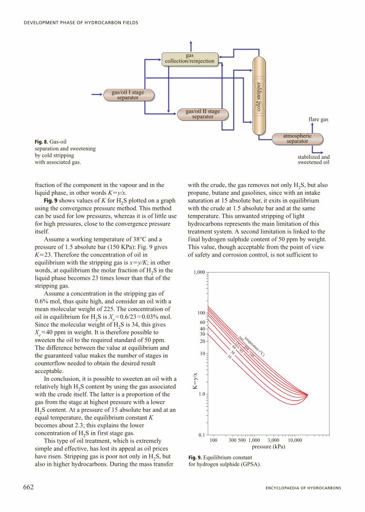
greater detail. The purpose of the latter is to separatethe two phases, producing a gas stream and astabilized oil, in other words, two intermediateproducts, since both will undergo furthertransformation before they can be considered finalproducts.
As far as the main product is concerned (i.e. thecrude oil), it has already been noted that treatmentmainly involves rendering it stable under storage andtransportation conditions. Since the latter twooperations are usually carried out at ambienttemperature and atmospheric pressure, stabilizing theoil involves separating it from associated gas toguarantee a vapour pressure lower than or equal toatmospheric pressure. This is usually done with amultiflash system, involving a multi-stage separationat decreasing operating pressures, from the pressure onarrival at the treatment centre to the final stage atatmospheric pressure. This is the simplest treatmentprocess, and remains fundamental in the separationand stabilization of oil. In the past, its simplicity wasincreased by the fact that only a small portion of thegas streams produced at decreasing pressures was usedfor field utilities, such as producing the electric energyneeded to operate the treatment plant, for oiltransportation and any heating required. Under theseconditions, the treatment system was basically limitedto a series of separation stages, usually three(maximum four), and the flares used to dispose of theassociated gas produced.
Since this type of plant has not been completelyabandoned, it is important to stress that a simplifiedtreatment has a detrimental effect on environmentalpollution and energy conservation. A further effectshould also be considered: the efficiency implied inthis type of choice. If all the gas produced byseparation were collected, compressed and sent fortreatment and subsequent use, the efficiency ofseparation would be less important: anything notrecovered as crude oil would be recovered as gas. Onthe other hand, if the gas is burned (or, as is morefrequent today, reinjected into the reservoir), a modest,though not negligible, amount of light liquid productsis burned or reinjected into the reservoir.
It is clear that the main purpose of a multiflashseparation system, or other type of stabilization system,is to maximize the recovery of light hydrocarbons. Thisincreases the production of crude oil, and increases,though only slightly, the product’s API gravity.
Generally speaking, in order to increase therecovery of liquids, the number of separation stages isincreased. Consider an oil stabilization process withonly two stages: one under pressure and one atatmospheric pressure. This solution is adopted forproduction tests with fluid sampling for PVT analysis.
650 ENCYCLOPAEDIA OF HYDROCARBONS
DEVELOPMENT PHASE OF HYDROCARBON FIELDS
Production tests are carried out at sufficient pressureto obtain the production parameters of the wells. Inorder to translate well production into stock tankconditions (i.e. atmospheric pressure), the liquid phasecollected by the test separator is operated atatmospheric pressure. The resulting product isstabilized oil under stock tank conditions. On the otherhand, the two gas streams, at the separator and at theatmospheric stage, are extremely rich in lightcompounds, which, if a different method wereemployed, may remain dissolved in the oil, thusincreasing its quantity and quality. If the deliverypressure of the wells, and consequently that on arrivalat the gathering centre, is sufficiently high, it ispreferable to pass from two to three, or even fourstages (three plus an atmospheric stage). Sincerecovery or losses, depending on the point of view, arelinked to associated gas in the first stage, and todissolved gas in the other stages, it is preferable to useseveral stages in order to free the latter. Consideringthat, all other parameters being equal, dissolved gas isdirectly linked to pressure, the higher the pressureduring the first stage of separation, the greater thedissolved GOR in the liquid separated, and thus thehigher the recovery of liquids if several stages ofequilibrium are used at intermediate pressures betweenthe original pressure and final atmospheric pressure.
It is important to stress that the recovery of liquidsis not alone in benefiting from the subdivision intoseveral separation stages; this is also true of anyseparated gas that anyhow must be recompressed fromthe working pressure at which it was produced to therequired final pressure through a series ofcompression stages.
Another important parameter in the stabilization ofoil by separation is the working temperature of theatmospheric stage. Under normal conditions, a valueof 40°C, giving a true vapour pressure slightly belowatmospheric pressure, reduces losses from evaporationto a minimum (see Section 5.3.6). Moreover, instorage tanks the Reid vapour pressure is very low, inline with common transportation regulations. It can beobserved that vapour pressure is mainly due to a fewcomponents, ranging from methane to the butanes.
If, for the sake of simplicity, Raoult and Dalton’slaws (valid for perfect gases) are applied to thehydrocarbon mixtures under consideration, and oneconsiders the vapour pressures of their purecomponents, thus follows P��Pi Xi; where P is thevapour pressure of the mixture, Pi Xi is the partialpressure of the i-th component, Xi is its molar fraction,and Pi the pure component vapour pressure. Since theinteraction between the components is modest, usingthe laws cited above does not result in significantdeviations (more conservative values are generally
obtained than those resulting from bubble pointcalculations using the adequate equations of state).
Considering the case of two-stage separation, it isevident that the amount of methane and ethane presentin the stabilized oil is not negligible. The contributionmade by these components to vapour pressure is evenmore significant. Assuming a loss in the order of 0.2%in volume during storage, this loss, translated into thepercentage of moles, becomes far more significant. Inthis case, the oil’s final dry gas content (i.e. methaneand ethane) is evidently subject to considerablevariation. Similarly, the final vapour pressure of thecrude undergoes a significant variation. Basically, thestabilized and stored crude may reach an acceptablevapour pressure during storage itself, which thusimproperly becomes the final stage of oil stabilizationprior to transportation and commercialization.
This mechanism explains why in many cases,especially for relatively light oils (API gravity�36°)with low viscosity, it is unnecessary to control thefinal separation temperature to obtain adequatestabilization, since this occurs during the period instorage. In practice, separation thus occurs at the sametemperature as that of arrival at the gathering centreand treatment.
This practice is not always advisable, in part sincethe temperatures of the fluids delivered by the wellsmay be very high, and remain so in the gatheringsystem. This occurs relatively frequently in thedevelopment of onshore fields. If the productivehorizon is fairly deep, for example 4,000 m, as is oftenthe case for recently discovered oil fields, thetemperature may be over 120°C. In unusual cases itmay be as high as 150°C at depths only slightly above4,000 m. Under these conditions, even taking intoconsideration the cooling along the well string (notsignificant) and the more significant cooling along theburied pipeline, the fluids may reach treatment plantsat a temperature of about 100°C. This temperature isnot at all ideal for multiflash stabilization. Theopposite condition prevails in offshore fielddevelopment. In this case, the fluid may cool verysignificantly inside the subsea pipelines, and thetemperature of the oil gathered at the entrance to theseparation plants may be too close to that of theseafloor (12°C in temperate seas, such as theMediterranean). At this temperature, it may becomedifficult to separate the two phases due to theincreased viscosity of the liquid. If the temperature atthe final stage is not controlled, the vapour pressure ofthe stabilized product will be too high. Even withouttaking into consideration cooling due to adiabaticflashes, at the atmospheric stage the oil would have atrue vapour pressure at 30°C far in excess of anatmosphere (1.8 absolute bar), and the Reid vapour
651VOLUME I / EXPLORATION, PRODUCTION AND TRANSPORT
TREATMENT PLANTS FOR OIL PRODUCTION
pressure would be too high. In this case, thetemperature of the final separation stage must beraised. Until now, the final stage has been consideredatmospheric; actually, if one wanted to recover the gasproduced by this separator through compressing it, onecan maintain working pressure at values aboveatmospheric pressure. Even when the gas is burned ina flare, the working pressure is greater than or equal to1.2 absolute bar.
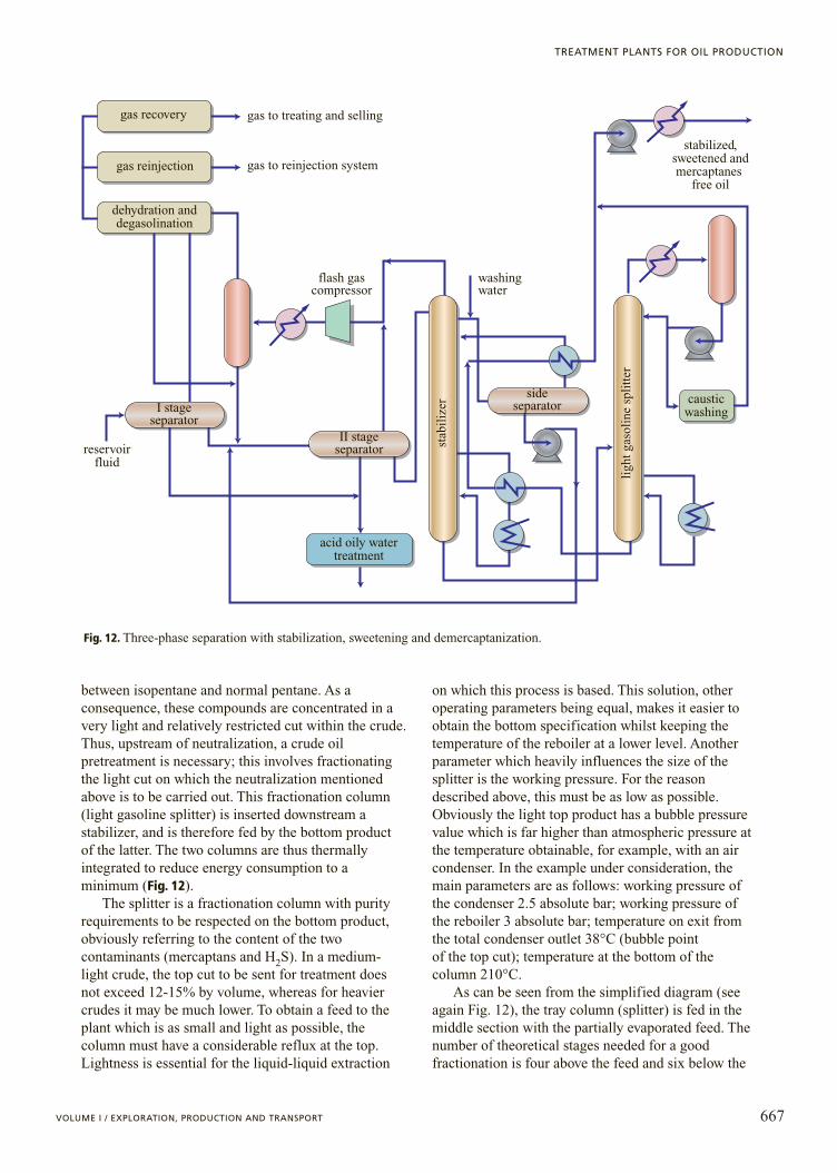
If this new operating parameter is taken intoconsideration, it is easy to calculate the temperaturerequired to obtain the desired degree of stabilization. Inmany cases, the optimal pressure value in the separatoris in the order of 1.7 absolute bar; for the purposesdescribed above, the working temperature needed toobtain a Reid vapour pressure of 10 psia is 75-80°C.This means that significant heating is required beforethe final stage. As the diagram in Fig. 3 shows, the gasfrom the final and intermediate stages is recompressedand mixed with the stream from the preceding stage. Inthe final stage, the gas is cooled before the relevantcompression stage and the condensed liquids are mixedwith the stabilized crude.
As far as the first separation stage is concerned, andfrequently the intermediate stage as well, no heating isinvolved unless there are further problems, which willbe discussed later (dehydration, desalting). The lowtemperature of the first two stages leads to a reductionin the loss of light hydrocarbons in their respective gasstreams. The gases are separated under conditions ofthermodynamic equilibrium with the liquid under the
relevant temperature and pressure conditions. Inconclusion, a multiflash oil separation-stabilizationsystem produces maximum recovery if the temperaturesof the first stages are kept as low as possible, and thetemperature and pressure of the final stage areappropriately regulated by heating.
That which occurs when oil arrives at the separatorat moderate temperature (i.e. lower than or equal to thatof the environment) was previously addressed.However, when oil enters at very high temperatures asdescribed above, the contrary may occur; in otherwords, it may be necessary to cool all three gas streamsproduced by the separators, or even to cool the wholestream entering the separation unit. Clearly, thecondensates produced by the cooling of gas, includingthat from the first stage, are recycled in the separatorsthemselves (in the subsequent stage). This condition isnot unusual; in many cases, alongside simple cooling, atrue condensate removal system by refrigeration may beused for all of the associated gas (see Chapter 5.4). Theliquids produced in this way can be treated andfractionated as described in the chapter cited, and maybe commercialized separately if they are produced insufficient quantities to render this operationeconomically viable. In many cases, the condensateobtained by its removal from gas can be recycled andcommercialized through the crude oil itself, bystabilizing the entire stream. This solution is usefulwhen the gas is later reinjected into the reservoir, eitherto save energy or due to productive problems with thereservoir. In this case, condensate removal serves to
652 ENCYCLOPAEDIA OF HYDROCARBONS
DEVELOPMENT PHASE OF HYDROCARBON FIELDS
I stageseparator
II stageseparator
III stageseparator
reservoir fluid
wash water
stabilized and desalted oil
associated gas
MP compressor
LP compressor
oily watertreatment
gas recoveryand/or injection
Fig. 3. Three-phase separation with heating and desalting. MP, medium pressure; LP, low pressure.
maximize the immediate recovery of liquids, and thereis thus no need to meet restrictions on the dew point ofthe gas. By contrast, where it is preferable tocommercialize the associated gas, a more stringentcondensate removal process may be necessary, with theproduction of liquefied petroleum gases as a thirdproduct. The LPGs extracted cannot always be mixedwith the stabilized oil stream. In essence, it is notalways possible to comply with two conflictingrestrictions without producing a third product.
It is evident that, starting from a very simplescheme, a larger and fairly sophisticated stabilizationsystem can be obtained. Today this type of situation iscommon.
A so-called ideal separation or stabilization of areservoir fluid involves subdividing the recombinationinto two streams: one of vapour and the other ofliquid. The latter contains all the liquid componentswhich are liquid at ambient conditions (i.e. the C5�),while the former contains all of the volatilecomponents (i.e. methane, ethane, nitrogen and CO2).Regarding propane and butane, which are the keycomponents of the fractionation, the liquidhydrocarbon stream contains normal butane isobutaneuntil the acceptable vapour pressure (RVP�0.7absolute bar) is reached. In many cases, to obtain thisvalue, the above-mentioned stream also contains someof the propane present in the recombined reservoirfluid, while the remainder is found in the gas stream.
This method allows two different types of analysis tobe carried out. First, it is possible to calculate simplyand effectively the actual performance of a separationsystem by comparing the oil stream stabilized by twoor three separation stages with the liquid stream of anideal stabilization system; a stabilization system canthus be considered optimal the closer it comes to thesolution described. Second, ideal separation makes itclear from the first data available (reservoirrecombination) whether and to what extent thereservoir fluids can be subdivided into only twostreams, providing a gas and a stabilized liquid oil thatmeet the basic restrictions for transportation and/orcommercialization. This condition, which hasenormous economic benefits (smaller investments)and is of great operational simplicity, can be obtainedas long as the stabilization of the crude is carried outin an adequate way. In other words, it must be as closeas possible to a fractionation, and not a roughseparation obtained by flash. As the examplesprovided show, the latter produces a stabilized liquidstream whose vapour pressure is mainly due to thepresence of methane and ethane. These twocomponents can be reduced to a minimum, so thatthey contribute only negligibly to the vapour pressureof the stabilized oil. This does not require an ideal oroverly sophisticated plant (see Section 5.3.4).
Clearly, a significant percentage of butanes, exceptin very unusual cases, can be contained in oil with a
653VOLUME I / EXPLORATION, PRODUCTION AND TRANSPORT
TREATMENT PLANTS FOR OIL PRODUCTION
gas recoveryand reinjection
MP gascompression
LP gascompression
oily watertreatment
stabilizedoil
HP
man
ifol
dM
P m
anif
old
LP
man
ifol
d
Fig. 4. Three-phaseseparation with three deliverypressure levels.HP, high pressure.
RVP below or equal to 10 psia. Often a non-negligibleamount of propane may also be acceptable.
In evaluating the multiflash separation system, forthe sake of simplicity it was assumed that theproduction of the field under examination formed asingle stream. All of the wells, regardless of operatingconditions, thus enter a single manifold at the end of thegathering system, which collects and uniforms theentire production. Note that in this case the entireproduction is treated under the well conditions with thelowest working pressure when it reaches the gatheringcentre. In the initial phase of reservoir exploitation, thiscondition does not cause significant problems since allof the wells generally deliver at similar pressures.However, if these pressures vary greatly, as is the casefor some producing fields, several production manifoldsoperating at different pressures are needed (e.g. high 80absolute bar, medium 30 absolute bar, low 9 absolutebar). For wells producing at high pressure, the firststage at 80 absolute bar is followed by three furtherseparation stages at medium, low and atmosphericpressure. The production at medium pressure by-passesthe first stage and enters directly into the second, whereit is mixed with the saturated liquid from the first stage.The production at low pressure enters the third stageand is followed by only a single stage at atmosphericpressure (Fig. 4).
Basically, the example given shows that separationparameters, and more generally treatment parameters,must above all be adapted to field productionparameters. Furthermore, when associated gas isrecovered or injected, a compression system for thelatter is needed. Often it is the compression of gas atthe various stages of separation (which is far moreexpensive than separation) that dictates the optimaloperating parameters. Taking this into consideration, itis clear that the operating parameters for separationoften differ from the optimal parameters for maximumrecovery.
As far as construction materials are concerned, fora simple gas-oil separation carbon steel is used for allthe vessels, even in the presence of corrosivecompounds dissolved in the liquid. This choice ismotivated by the significant filming tendency of crudeoil, which create an effective self-protection of all thesurfaces that it wets. Regarding the internals, the wiremesh pad and straightening vanes, stainless steel isgenerally used (with a variable nickel-chrome content,e.g. AISI 304). In this case, the metal wire mesh padmust be perfectly electrically isolated from itssupports, which are welded to the vessel. This avoidsthe formation of micro-cells due to the differentelectrochemical potential of the two materials and theconsequent passage of a current, which would causesignificant corrosion of the separator wall.
Oil-water separationUntil now, only aspects concerning the oil-gas
phase equilibrium and the final stabilization of thecrude have been considered. Field separationprocesses also have another aim, that of separatingthe water phase potentially present in the reservoirfluid.
The specification to be met is 0.5% in volume ofresidual water cut. Under normal separationconditions, when the oil has low viscosity andmedium-low density, the separation of water (thusmeeting this specification) does not require specialfeatures. It is sufficient to use three-phase gas-oil-water separators instead of simple two-phase gas-oilseparators; these allow the two liquid phases to beseparated as well. This introduces a new topic,concerning the typology and characteristics of theseparators used in oil fields, where the mostimportant phase treated is the liquid hydrocarbonphase.
For a more detailed gas-liquid separationdescription, see Chapter 5.4. The separationmechanism used for drops of liquid suspended in thegaseous phase is identical; the coalescence systems forthe drops dispersed in the gas phase are also similar, asare the internals used, identical also in terms ofinstallation. The configuration of oil separators oftendiffers from that of gas separators. Except in rarecircumstances, the most frequently used separator inoil fields is of horizontal type, whereas verticalseparators are more common for the separation of gas.The reason for this is clear: since the liquid phase isthe most important, the oil separator must hold theliquid for a period of time sufficient for the gas phasedispersed in the liquid to be separated and reach theinterface between the two fluids as the liquid passesthrough the separator.
Adding to this the need to separate the two liquidphases of water and hydrocarbons, it is evident that theholdup time required may increase considerably.Basically, the sizing and/or the operational evaluationof a single separator can be represented by thesemplified movement of particles, in this case spheres,suspended in a dispersing fluid (drop dynamics). Thereare several equations that represent the decantation ofparticles in a fluid, each with its own field ofapplication; below, that most commonly used for aliquid-liquid separation will be examined.
The motion of a drop of liquid dispersed in a gas orin a dispersing fluid, like that of a bubble of gasdispersed in a liquid, reaches a steady condition whenthe resultant of external forces (force of gravity,buoyancy, the resistance of the medium) is nil. Thiscondition, i.e. in the field of relatively low Reynoldsnumbers; as for example that relating to liquid-liquid
654 ENCYCLOPAEDIA OF HYDROCARBONS
DEVELOPMENT PHASE OF HYDROCARBON FIELDS
separation and, in this case, the separation of oil andwater, can be represented by Stokes’ well-known law:
Vt�1,488gDp2(r1�r2)/18m2
where Vt is the settling velocity in ft/s; Dp is thediameter of the particles in ft; g is the acceleration ofgravity (32.2 ft/s2); r1 is the density of the dispersedliquid in lb/ft3; r2 is the density of the dispersingliquid in lb/ft3; m2 is the viscosity of the dispersingfluid in cP (1cP �10�3 Pa�s).
The formula under examination does not apply tothe separation of drops of liquid dispersed in a gassince the Reynolds number, in this case, is always veryhigh; however, it is extremely relevant to the analysis ofthe separation of drops of water suspended in a liquidhydrocarbon phase. Its field of application, concerninglow Reynolds numbers, is compatible with the size ofthe suspended particles present (up to 100 mm). Theequation highlights the three essential parameters ofthe analysis being carried out: the diameter of theparticle (which has the greatest impact on thephenomenon, being raised to the second power), thedifference in density between the two liquids, and theviscosity of the dispersing fluid (i.e. the oil).
It is important to note that these physical propertiesmust be referred to as the temperature and pressureconditions of the separator. In the case of thehydrocarbon phase, this means that density andviscosity must refer to the saturated liquid at bothtemperature and pressure conditions, which differconsiderably from those of the oil under stock tankconditions made available through analyses. At a fixedtemperature, the solution GOR of each separation stage
is quite proportional to the operating pressure which isat its maximum in the first stage. This fact leads to aconsiderable reduction of both the density and theviscosity of the saturated oil. Since the density of thetwo liquid phases is of the same order of magnitude,even a small variation in the density of the oil mayincrease the difference in density between the twoliquids significantly, and thus the correspondingsettling velocity. The data from PVT analysis or simpleflash calculations make it possible to determine thesolution GOR and the density of the saturated liquid.
As far as the viscosity of the latter is concerned, Fig. 5allows one to calculate the reduction in viscosity inpassing from stock tank oil to saturated oil as a function ofthe solution GOR. For example, assuming an oil havingthe following characteristics: stock tank density of 0.842,viscosity of 10 cP at 40°C to be treated at a workingpressure of 35 absolute bar and a temperature of 40°C,corresponding to a solution GOR of about 250 SCF/stb(from the material balance), with the help of Fig. 5 theviscosity of the dispersing fluid can be determined, whichturns out to be 3.3 cP. The variation in viscosity aloneleads to a settling velocity three times higher in the firststage separator than in the atmospheric separator.
Given an identical temperature, the effect ofvariations in density must also be added; thoughmodest, these have a similar effect; correspondingdensity of saturated oil with a solution GOR of 250SCF/stb becomes 0.8 ca. Dr1�9.86 and Dr2�12.48lb/ft3. Overall, the ratio of the two settling velocities atidentical temperature is 3.83. It is easy to see that theholdup time in the separator can be reducedproportionally in order to obtain the same degree of
655VOLUME I / EXPLORATION, PRODUCTION AND TRANSPORT
TREATMENT PLANTS FOR OIL PRODUCTION
600400
200
100
6040
20
10
64
2
1
0 100 200 300 400 500 600 700 800
500
3002001007050403020151075432
absolute viscosity of gas free crude at reservoir temperature
visc
osit
y of
sat
urat
ed o
il (
cP)
gas in solution (ft3/bbl)
0.60.4
0.2
0.11,000 1,200 1,400
1.51.00.7
Fig. 5. Viscosity of saturated oil as a function of solution GOR (Katz et al., 1959).
separation. Alternatively, taking into account the impactof the diameter of the particles, with an identicalholdup, drops with a diameter 3.83�2�1.96 timessmaller can be decanted.
The above example makes it easy to understand theinfluence of the main operating parameters on theseparation of water dispersed in oil. To obtain moredetailed calculations, and to calculate the size of aseparator guaranteeing the required residual watercontent, the distribution of the particles in a water oilemulsion must be known. Although numerousexperiments have been carried out on this topic, it isextremely difficult to obtain precise data: it is not easyto quantify the degree of emulsion of water in a crude.This clearly depends on the properties of the two fluids,but it is certainly not sufficient to know their densityand viscosity to quantify the degree of dispersion of thewater drops. This depends on the path followed by theemulsion from the reservoir, through the well and itspressure control systems at delivery, up to arrival at thegathering system, and on the pressure drop during thestages of separation. In a three-phase gas-oil-waterseparation, some pieces of information, dictated byoperational experience, allow this problem to beovercome in part. A liquid-liquid separation, unlessanomalous factors such as those relating to extremelyviscous oils intervene, may be carried out quite simply.
It is common knowledge, supported by numerousfield tests, that the size of the water drops to beseparated in order to obtain an adequate dehydrationmust be in the order of 100-150 mm. This means that, ifthe separator is designed so that drops with a diameterlarger than or equal to the predetermined diameter canmake the vertical journey from the gas-oil interface tothe oil-water interface, a residual water content lowerthan the required 0.5% in volume can be obtained.
Suppose, for example, that the cylindrical part of thehorizontal separator has a diameter and length of 2.5and 10 m respectively, and that the gas-oil interface is
maintained at the middle of the vessel. Consider that theoil-water interface is kept 450 mm above the bottom ofthe tank and that the holdup time for the oil is about 5minutes. The water particle to be decanted must cross amaximum layer of 800 mm in 5 minutes – in otherwords, it must have a settling velocity of 160 mm/min(0.52 ft/min). Applying Stokes’ law for a particlediameter of 100 mm would result in a velocity eighttimes lower than this, and, therefore, it would beimpossible to reach the required value for residual watercut. On the other hand, if one calculates backwards toobtain the diameter of the drops that can be separated, avalue of about 300 mm is obtained, which unfortunatelyprovides an inadequate separation.
At this point, coalescence devices should beintroduced. In the case of drops suspended in a gas, awire mesh pad is inserted in the vertical separator usedto decant the drops to obtain a good separation. Thissimple and cheap device guarantees an adequatecoalescence of the drops of liquid suspended in the gas,forcing them to collide in the obligatory path through themesh itself. A similar result is obtained in normal liquid-liquid separation, as in the case of light condensate, LPGand gasoline, by inserting a coalescence device identicalto that used for gas into the liquid-liquid separator.
With oil, on the other hand, it is impossible to usethis type of coalescence device, suitable for light andextremely clean fluids. Oil requires a coalescence systemthat, working with a fluid with a high content insediments of various type, must provide large spacesthrough which to pass. This problem is tackled byinserting a coalescence section consisting ofstraightening vanes, suitably distanced and placed atdifferent angles (45° or 60°) parallel to flow inside theseparator (Fig. 6). Usually this occupies the wholesection through which the three phases of gas, oil andwater must pass; the straighteners also facilitateseparation in the gas phase, and in the bottom waterphase. In order to facilitate deposition, and thus the
656 ENCYCLOPAEDIA OF HYDROCARBONS
DEVELOPMENT PHASE OF HYDROCARBON FIELDS
oil
water
buffle
vortex breaker
three-phase separator
gas
straighteningvanes
sive traymomentumabsorber
demister
Fig. 6. Internal view of a three-phase separator (A) and straightening vanes (B).
A B
removal of suspended solids (sand, colloidal clay, etc.), itis sometimes preferable to leave the lower part, devotedto the water phase, free. The distance that the drop mustcross is reduced to extremely low values. If we have anangle of 45°, the vertical distance between two vanes is2�2i, where i is the distance between the two vanes(50-75 mm). If the whole separator is filled with thepack of straightening vanes at 50 mm intervals from oneanother, this leads to a reduction in the diameter of theseparated particles of (1.4�50/800)�2�0.3; in otherwords, a value slightly below the required value of 100mm. When the drops, whose size is larger than thatcalculated, reach the surface of the vane, the wall effectcauses them to coalesce and the separation reaches therequired value. However, the example given is a limitedcase; usually heating is used to improve separation.Longer holdup times can also be applied, in part becauseit is not practically viable to fill the entire cylindrical partof the separator with straighteners.
If the gas flow rate is very low, as in the two stagesfollowing the first stage, the level of the liquid can bekept above the centre line to increase the holdup timewithout changing the size of the separator. It isimportant to note that this solution is effective ifstraightening vanes are present. If the inside of theseparator is empty, increasing the holdup by increasingthe height, and thus the vertical journey, is notparticularly useful; as a result, vertical separators arerarely used for this purpose. For the separation of dropsof liquid from gas see Section 5.4.2.
Oil-water separation is not significantly differentfrom gas-oil separation in terms of the choice ofmaterials. The straightening vanes described above arealso made of extremely thin sheets of stainless steel(AISI 304, or other even more valuable types). If theassociated gas and the oil contain acid gases, theseconcentrate in the water phase proportionally to theirfractional pressure. If this pressure is high (greater thanor equal to 1 bar), the watery solution becomes acidic,and thus corrosive. The protective film formed by theoil also disappears. During the pressurized separationstages, the part of the tank below the water-oil interfaceis protected by clading with stainless steel (AISI 316-Lor duplex steel 3 mm thick). Finally, it should be notedthat corrosion in the water phase is often increased bythe high concentration of salts.
5.3.4 Treatments
Desalting
Desalting by washing with waterThe above discussion makes it possible to stress
that a good three-phase separation is able not only to
stabilize the oil, but also to dehydrate it to the requiredvalues. Returning to the properties of formation waterand particularly its salinity, as said earlier, it is oftennecessary to desalt the crude by reducing the salinityof the emulsified water.
A desalting system consists of a mixer-settler typesystem which allows the salinity to be diluted bymixing the oil with washing water with a low saltcontent (1 g/l). The diluted water is then separated outby decanting, thus bringing the oil to the same orlower value for water cut as before mixing. Thisequipment can be inserted downstream of separationas an additional unit. In this case, the intake to thedesalting system is a separated and stabilized crude,but with excessive salinity.
Consider, for example, a crude with a water cut of0.5% in volume and a water salinity of 50 g/l. Thesalinity of the oil is thus about 87 ptb, whilst the valueto be guaranteed is 20 ptb. Assuming an identical finalwater cut, the system therefore requires an effectivedilution of about 1/5. Since the quantity of water to bediluted is modest, injecting an amount 3% in volumeor greater is sufficient. Often dilution is obtained byinjecting water into the feed line. The most commonmixing device is a lamination valve which, byproducing sufficient turbulence, facilitates contactbetween the two phases of oil and water. Using thissystem leads to a considerable loss of head; in the caseunder consideration, downstream an atmosphericseparator, a feed pump will be needed to transfer theintake from the separator to the desalter. The mixingefficiency is obviously less than one. If we use amixing valve and have a very low washing water/cruderatio, 3% as in the example given, the efficiency of themixing process is not much above 70%.
Since the treated product has a fixed water cut of0.5% by volume, a simple in-out balance for saltindicates that the content is 10.4 g/l. The salinity of thecrude is thus 18.1 ptb, meeting the required value. It isimportant to note that in the example given it wasassumed that the washing water has a salt contentequal to or less than 1 g/l. If brine with higher salinityis available, it is sufficient to raise the washingwater/feed ratio slightly. In this type of equipment,using a water flow rate below 3% leads to inefficientmixing; it is therefore pointless to improve the degreeof liquid-liquid separation to a water cut below 0.5%by volume. The separator used thus works exactly likethat described above. It is obvious that a multiflashseparation as described above allows this new functionto be integrated without the need for additionalequipment; the washing water is simply injectedbefore the final separator. As such, the first separationstage functions as a dehydration stage, reducingformation water to 0.5% in volume as seen above.
657VOLUME I / EXPLORATION, PRODUCTION AND TRANSPORT
TREATMENT PLANTS FOR OIL PRODUCTION
Washing water can also be mixed by other devices,such as a static mixer. This equipment closely resemblesstructured packing, and supplies the necessary surfacearea to create close contact between the two phases ofoil and water. Basically, a true stage of equilibrium inequicurrent is obtained. The latter characteristic affectsboth efficiency, which becomes very close to one, andthe loss of pressure, which becomes negligible. Anotheradvantageous property of this equipment is that it mixesby contact over a large surface area, which does notcause excessive dispersion and the consequentstabilization of the emulsion, as is the case if a valve isused. This phenomenon also occurs in the multiflashseparator described above, where the oil passes throughthe level control valve, rendering subsequent decantingless efficient. In the example analysed, desaltingconditions are relatively favourable. We have considereda crude of medium density, but with relatively highviscosity (in most cases viscosities are lower, anddensities more favourable). The treatment described cantherefore be used with excellent results and modestwater consumption.
When desalting treatment is carried out offshore, itis obvious that the dilution water used cannot beseawater as it is. Treating the crude therefore becomesmore expensive since the seawater must first bedesalinated, using one of a variety of methods. Thesimplest and most frequently used is based on reverseosmosis and can supply water with negligible salinityby using two stages of separation with semipermeablemembranes. Since the crude is usually very salty, it isnot necessary to completely desalinate the washingwater. A single stage of purification is thereforeenough, supplying water with a residual salinity lowerthan or equal to 1 g/l, sufficient for this purpose. Underother conditions, such as in the desert, it is possible touse brackish water with a salinity of 2-3 g/l withoutnotably increasing the amount of washing water.
The waste waters from crude oil dehydrationand/or desalting are oily waters containing largeamounts of suspended solids, and therefore requiresuitable treatment before they can be discharged.
In liquid-liquid separation the watery phase at thebottom of the separator also behaves like an emulsionin which the dispersed liquid is the oil itself, and thedispersing phase is water. In this case, during theholdup in the separator, the hydrocarbon dropsdispersed in the water follow an inverse process to thatof the overlying oil phase. In the example separatordescribed above, the bottom section devoted to wateris kept at a predetermined level (450 mm). By varyingthis parameter, the water can be given the minimumholdup time required to obtain the desired purity.
To avoid overloading the subsequent water deoilingtreatment excessively, the degree of separation most
frequently required from separators is 500-1,000 ppmof oil dispersed in water, in other words 0.05-0.1%.This specification is more restrictive than that for oil.However, it should be remembered that the viscosityof the dispersing fluid is very low (0.6-0.4 cP) underthe temperature conditions of the first and third stagerespectively. By applying Stokes’ law as above, sincethe difference in density is identical, and viscosity 10times lower, a suspended particle of identical diameterhas an ascending velocity ten times higher. Adding tothis the fact that the distance to be covered is shorter,slightly less than 5 minutes are needed for a particle totravel the entire vertical distance. As it is difficult tomaintain holdup times lower than 3 minutes and obtaina good level control the required clarification of thewater inside the separator can therefore be obtainedwithout the need to use straighteners or changing theholdup time.
The water decanted from the separator is firstdegassed in a flash drum, and then deoiled with aprimary treatment consisting of a horizontal settlingtank (API skimmer) or a CPI (Corrugated PlateInterceptor), and with secondary treatment (filtrationor floatation).
For offshore treatment, and recently for onshoretreatment as well, the API skimmer has been replacedby cyclones based on the centrifuge principle, whichallow acceptable values for suspended oil (30 ppm) tobe obtained. International standards for open seaconditions specify a limit value of 40 ppm, whereasfor inland and coastal waters the most frequentlyrequired value is 10 ppm. In this case, deoiling withsecondary treatment, the most common of which isfloatation, is needed.
Electrostatic desaltingThis treatment process is common practice in
refineries where the feed to the primary treatment ofcrude fractionation (topping) requires a salt contentbelow 3 ptb. In refineries it is more important than infield treatment to keep the flow rate of washing water toa minimum, and this can be done by minimizing thesalinity of the crude oil entering the system, followingthe criteria described above, and above all by keepingresidual water after separation to values of 0.1-0.2% involume. These specifications are easy to meet withmedium-light or light crudes, even in field treatment,especially when the viscosity of the stabilized oil is low(1-2 cP at ambient temperature). In simple multiflashseparation, as a result of gas saturation in the first stageand heating in the following stages, extremely lowviscosities, below 1 cP, can be obtained; these allowwater contents far lower than the required 0.5% involume to be obtained with only minor modifications tothe sizing of equipment. The greater ease of separating
658 ENCYCLOPAEDIA OF HYDROCARBONS
DEVELOPMENT PHASE OF HYDROCARBON FIELDS
emulsified water in the field as opposed to the refinerycan be explained by the different properties of thecrude. When the oil exits the wells it has not undergoneoxidation processes. Under original conditions its high-boiling components, especially asphaltenes, are thosefound in the reservoir. On contact with air, which occursin the stock tank as a result of breathing, and whichcontinues in the oil tanker used for transportation, thecrude undergoes a weathering process which changes itprofoundly, increasing the presence of strongly surface-active compounds, which dissolve or accumulate ascolloids suspended in the drops of water. This change incomposition, added to the reduction in light compoundswhich have a fluidifying effect, causes a markedincrease in the strenght of the emulsion, although theincrease in viscosity is not equally significant.
A practical and simple system for evaluating theeffects of the weathering of the crude and thestabilization of emulsions is that known in technicaljargon as a bottle test. These tests involve taking liquidsamples which are heated and centrifuged in astandardized equipment for the time required to separateout the water. The tests are also carried out with theaddition of various demulsifying compounds in order toevaluate their effectiveness. If a bottle test is carried outat the mouth of the well, even if degassing is carried out in a very rough way, the results, compared tothose which can be obtained in the laboratory with aweathered sample, are completely different and better. Inshort, the temperature at which the emulsion breaks islower, and the separation time is lower. For this reason,refineries use an electrostatic desalting system. This iscarried out hot, in other words the treatment forms partof the system used to preheat the feed to hightemperatures (100-130°C), even for crudes which are notparticularly viscous or dense. Heating and theelectrostatic coalescence of the suspended drops of wateris often coupled with the use of demulsifying chemicals,which ease the process of breaking the emulsion.
The principle on which electrostatic coalescence isbased is easy to understand. The emulsified water drophas a strong surface tension which prevents, orhinders, the aggregation of several drops, which wouldallow these to reach the settling velocity required forseparation. This is due to the presence of modestquantities of surface active compounds. The drop ofsalty water, being a polar substance, behaves like adipole when subjected to an electrostatic field. Theapplication of a high voltage alternating electric field(10,000 volts or above) in addition to orienting thedipoles, elongates the drops, deforming their sphericalshape into a ellipsoid, in which the larger diameterbecomes ten times larger than the original diameter. This alternate stretching has two positiveeffects: the film covering the particle is thinned,
facilitating its rupture, and above all, it eases thecollision of the drops, which find themselves at adistance of less than ten diameters from one another.
This causes an enlargement of the drops, whichthus settle more easily; the mean free path between thevarious particles becomes ten times the diameter of theparticles. The latter consideration makes it easier tounderstand why the distribution of the drops created inthe suspension is extremely rarefied, and allows us toguarantee a final content of 0.1-0.2% by volume.
Whereas in refineries, due in part to the higherflow rates, electrostatic desalters are used for medium-low viscosity oils, in the field this type of treatment isused only for extremely heavy and viscous crudes.
It should be stressed that applying an electric fieldof several thousand volts to an emulsion of water in oilis possible because of the high resistivity to thepassage of electric currents the emulsion has. Thismeans that the difference in voltage applied to thegrids, which causes the effects described above, can bemaintained with a very modest consumption ofelectric power. For this to occur, the emulsioned watermust not be too fragmented, and the amount of water in the emulsion must not exceed 15% byvolume. With higher water cuts, or because of too highmixing valve pressure drop, the electric conductivityof the bath will exceed allowed values and theelectrical field short-circuits. To avoid this condition,the emulsion must undergo suitable pretreatment toreduce the water content to the value mentioned.
A second characteristic of the use of theelectrostatic coalescence separator is the absoluteguarantee that no gas bubbles will form inside it.Many vendors of this equipment prefer to feed theelectrostatic coalescer with a pump, so as to ensure anoperating pressure in the vessel of at least a bar abovethe bubble point of the treated fluid. Usually,electrostatic treatment is carried out in combinationwith heating; it is therefore necessary to evaluate thevapour pressure of the hydrocarbons carefully. At hightemperatures, water also has a significant vapourpressure which is added to that of the hydrocarbonphase. The vessel in which electrostatic coalescence iscarried out is therefore pressurized. Pressure increasesas the working temperature rises, and decreases themore the oil to be treated has been stabilized duringprior treatment. This is why this treatment is ofteninserted downstream the final separation stage. Onoffshore platforms where equipment are distributed onseveral floors, the desalter is usually placedimmediately beneath the final degassing stage. Thisavoids the need to use a feed pump for the crude.
Although electrostatic coalescence facilitatesseparation, it is good practice to use heating as well, inorder to shorten the holdup time, or to produce the
659VOLUME I / EXPLORATION, PRODUCTION AND TRANSPORT
TREATMENT PLANTS FOR OIL PRODUCTION
required water cut. To return to the example ofdesalting with multiflash, it was demonstrated thatmodest heating allows the crude to be stabilized athigher than atmospheric pressure. If the electrostaticsolution following the third separation stage is chosen,the heating used for stabilization facilitates desaltingat no further cost.
When a holdup time above 20 minutes is used forelectrostatic treatment, the maximum viscosity atwhich a good water separation (0.5% in volume) canbe obtained is 10 cP. This value makes it clear thatrecourse to this process is limited to very viscous andvery heavy crudes (20-25°API). Sometimes anelectrostatic coalescer is used cold to avoid heating.
Multistage desaltingWashing water represents a significant cost in the
desalting of crude oil, and it is thus preferable to keepthis to an absolute minimum.
When the formation water is extremely salty, itmay be helpful to use a two-stage treatment system.This unit often consists of two electrostatic coalescers.The first, which receives the maximum water intake,acts as a dehydrator; the second carries out the desireddilution with a water flow rate sufficient to guaranteethe requisite oil salinity.
Consider, for example, an oil with formation waterwhose salinity is 300 g/l, and specify as 20 ptb thesalinity of the treated oil. If the first stage functionssimply as a dehydrator, the lowering of salinity willdepend exclusively on the final water cut (0.2% involume), and not on the quantity of water entering thesystem. Assuming a maximum value for water of 15%,this gives a reduction of 96%. Nevertheless, salinityremains very high. The second stage therefore involvesdilution with washing water. Assuming an amount ofwashing water equal to 3% and a mixing efficiency of70%, the salinity of the water remaining in the crude isabout 26 g/l; with a residual water cut of 0.2% a valueof 18 ptb is thus obtained, in other words the requisiteoil salinity.
Taking into consideration the fact that the desaltingsystem forms part of the stabilization process, it isobvious that a good gas-oil separation can reduce thewater content significantly, at least to the value of 15%needed for the electrostatic separator to function. Inmany cases, during the productive life of the reservoir,the crude produced at the wellhead may contain 50%or more water. Under these conditions the well can nolonger produce spontaneously, and it will often benecessary to use an artificial oil lift system withsubmerged pumps installed inside the well. In this case
660 ENCYCLOPAEDIA OF HYDROCARBONS
DEVELOPMENT PHASE OF HYDROCARBON FIELDS
free water KOD
inletseparator
flash drum
water to treatment
washwater
stabilizedand desalted oil
fuel gas
electrostaticcoalescer II stage
electrostaticcoalescer I stage
water treatmentand reinjection
compressionand collection
trea
ted
oil
flas
h dr
um
Fig. 7. Oil desalting (20°API) with water separation at the wellhead and two-stage desalter at the gathering and treatment centre.
the emulsion of the formation water phase in the oilreaches its maximum levels. The emulsification due tothe passage of the reservoir fluid through the pumpmust therefore be reduced by injecting demulsifiersdirectly into its intake. This is followed by a gravityseparation directly at the wellhead, without the help ofan electrostatic field. This operation is aided byseveral factors. The first is the delivery condition ofthe well itself. Often a rough separation of associatedgas is carried out at the intake to the pump, before thereservoir fluid enters the pumping system. Thepumped liquid is thus at a pressure above its bubblepoint and remains so at the wellhead even when thedelivery pressure is relatively low. If we assume 15absolute bar as a pressure value under theseconditions, the oil does not liberate gas for the reasonsoutlined above, but has a solution GOR which, thoughmodest, renders the fluid less viscous and less heavy.
The second factor facilitating separation at thewellhead is the working temperature, which is fairlyhigh since the heat exchange along production tubingdoes not lead to significant cooling.
Assuming a flow temperature of 90°C, anextremely common value for an oil well, and addingtogether the effects of the dissolved gas andtemperature, it is clear why both viscosity and densityare much lower than those of the dead oil.
In conclusion, it can be stated that a significantamount of the water produced can be separatedwithout heating and/or electrostatic treatment. Theseparated water, given the quantities involved and itsproperties, is collected and reinjected into the reservoirfollowing pretreatment with cyclones and filtration.The oil treated in this way at the wellhead still has ahigh water content (5-10%), which can nevertheless beguaranteed with modest holdup times and simpleseparator internals (straightening vanes). The oil istransported with this residual content to the gatheringcentre, where it is treated using the systems describedabove. Sometimes it may be convenient to accept ahigher water cut, up to the standard 0.5% by volume,and to use a more sophisticated washing system(Fig. 7). Two-stage desalting is carried out with twowashing stages in counterflow, using the waterrecovered from the second desalter in the first stage.Assume a salinity of 180 g/l and a water/oil feed ratioof 5% by volume; with a residual water cut of 0.5% itis sufficient to inject 5% of water. This solution,assuming a mixing efficiency of 80% in the secondstage, gives a dilution ratio of 1/9, with a decrease insalinity to about 11% of the intake value. This gives asalinity of residual water of about 10.5 g/l,guaranteeing the required salt content. The waterdecanted with a lower salinity (8.5 g/l) can thereforebe used to reduce the salinity of the first stage from
180 to about 95 g/l. Using this system, the desiredresult can be obtained with a small amount of dilutionwater. Adopting the basic scheme of dehydrator plusdesalter, twice the amount of water would be needed.This result is obtained by adding a pump to recirculatethe decanted water from the second to the first stage.
As far as the choice of materials for desalting isconcerned, the same considerations apply as foroil-water separation, with particular emphasis on highsalt concentrations, and their negative impact oncorrosion, further accentuated when a high workingtemperature is needed.
Sweetening
When an oil has a high hydrogen sulphide content,the gas-oil separation and stabilization processes mustnecessarily take due account of this. The acceptablecontents were indicated above. In the past, a reductionof H2S in an oil which did not have particularly highcontents of this contaminant was obtained simply byincreasing the temperature of the final atmosphericseparation stage sufficiently. This solution can beconsidered makeshift, since hydrogen sulphide has avolatility very close to that of propane. With aspecification of 50 ppm by weight, in any case anextremely high value, the oil must be stabilizedexcessively, increasing the loss of light products, notonly propane but also butanes and gasolines. Thisprocedure may be defined as a ‘makeshift solution’.With flash distillation it is not possible to obtain aprecise fractionation of key components. In otherwords, this solution may be acceptable when the H2Scontent is relatively low, and therefore does not affectthe stabilization parameters for the oil. In all othercases, a specific treatment known as sweetening isneeded.
In the past, the cold stripping method wascommonly used. This system uses a stripping columnworking at close to atmospheric pressure, in which agas stream with a low-medium hydrogen sulphidecontent removes this component from the oil stream tobe treated (Fig. 8). This operation is known as coldstripping since it is unnecessary to heat the oil in orderto carry out the removal required. Were it necessary topreviously sweeten the gas used for stripping to obtainthe desired effect, this solution would no longer besimple and cheap.
In a stripping column the result of this process canbe described by the stripping factor S�KiV/L, where Kiis the equilibrium constant of the i-th component, inthis case the H2S, V and L are the molar flow rates ofthe vapour (stripping gas) and liquid (oil to be treated)respectively. The equilibrium constant, as is well-known, expresses the ratio between the molar
661VOLUME I / EXPLORATION, PRODUCTION AND TRANSPORT
TREATMENT PLANTS FOR OIL PRODUCTION
fraction of the component in the vapour and in theliquid phase, in other words K�y/x.
Fig. 9 shows values of K for H2S plotted on a graphusing the convergence pressure method. This methodcan be used for low pressures, whereas it is of little usefor high pressures, close to the convergence pressureitself.
Assume a working temperature of 38°C and apressure of 1.5 absolute bar (150 KPa): Fig. 9 givesK�23. Therefore the concentration of oil inequilibrium with the stripping gas is x�y/K; in otherwords, at equilibrium the molar fraction of H2S in theliquid phase becomes 23 times lower than that of thestripping gas.
Assume a concentration in the stripping gas of0.6% mol, thus quite high, and consider an oil with amean molecular weight of 225. The concentration ofoil in equilibrium for H2S is Xe�0.6/23�0.03% mol.Since the molecular weight of H2S is 34, this givesXe�40 ppm in weight. It is therefore possible tosweeten the oil to the required standard of 50 ppm.The difference between the value at equilibrium andthe guaranteed value makes the number of stages incounterflow needed to obtain the desired resultacceptable.
In conclusion, it is possible to sweeten an oil with arelatively high H2S content by using the gas associatedwith the crude itself. The latter is a proportion of thegas from the stage at highest pressure with a lowerH2S content. At a pressure of 15 absolute bar and at anequal temperature, the equilibrium constant Kbecomes about 2.3; this explains the lowerconcentration of H2S in first stage gas.
This type of oil treatment, which is extremelysimple and effective, has lost its appeal as oil priceshave risen. Stripping gas is poor not only in H2S, butalso in higher hydrocarbons. During the mass transfer
with the crude, the gas removes not only H2S, but alsopropane, butane and gasolines, since with an intakesaturation at 15 absolute bar, it exits in equilibriumwith the crude at 1.5 absolute bar and at the sametemperature. This unwanted stripping of lighthydrocarbons represents the main limitation of thistreatment system. A second limitation is linked to thefinal hydrogen sulphide content of 50 ppm by weight.This value, though acceptable from the point of viewof safety and corrosion control, is not sufficient to
662 ENCYCLOPAEDIA OF HYDROCARBONS
DEVELOPMENT PHASE OF HYDROCARBON FIELDS
gas/oil I stageseparator
gas/oil II stageseparator
atmosphericseparator
flare gas
stabilized andsweetened oil
gascollection/reinjection
cold
str
ippe
r
Fig. 8. Gas-oil separation and sweetening by cold stripping with associated gas.
100
604030
20
10
K�
y/x
260
149
12193
6638
16
204
100 300 500 1,000 3,000 10,000pressure (kPa)
1,000
1.0
0.1
temperature (°C)
Fig. 9. Equilibrium constant for hydrogen sulphide (GPSA).
guarantee good total acidity levels in the crude, andthus causes a significant drop in price.
All sweetening processes, given the particularchemical composition of the fluids treated, presentproblems of corrosion. In this type of treatment,working at ambient temperature, carbon steel withsuitable corrosion allowances (3-5 mm depending onthe concentration of acid gases) can be used for all theequipment wet by the oil, and particularly the strippingcolumn. When the gas injected is saturated in water atcolumn bottom conditions, the latter must be protectedwith a stainless steel plating.
Stabilization and stripping with a cold column
The paragraph on separations described a criterionallowing the efficiency of a stabilization system to bedetermined. Below, we will describe the plant thatcomes closest to the ideal distillation objective andallows for considerable savings, since it eliminates thenecessity for one of the two stages of compression ofthe separation gas required in order to recover thelatter. The stabilizing column operates under pressure,and the top gases are thus recovered directly withoutthe need for compression.
Fig. 10 shows a diagram of how this unit works.The oil from an initial separation stage at mediumpressure (21 absolute bar) is fed into the top of the
column working at a pressure of 7 absolute bar. At thebottom of the column is a reboiler allowing it tofunction. Controlling the temperature of the bottomproduct ensures that the required crude bubble point isreached, and thus the required stabilization. In order tokeep the vapour and liquid profiles in the column asuniform as possible, a second source of heat isincluded, with the insertion of an intermediate reboiler.This reboiler is fed, on the process side, bywithdrawing all the liquid using a chimney trayinserted at the chosen point in the column. The heatrequired for this service is supplied by the stabilizedproduct stream exiting the bottom of the column,which thus cools. This system has replaced thetraditional preheating of the feed with the bottomproduct. The most interesting result of this solution isprecisely the ability to keep the feed cold, thuseliminating the need for the top condenser present innormal fractionating columns. This makes the unit farsimpler and cheaper.
The main purpose of the stabilizing column is toguarantee the vapour pressure of the crude, forexample RVP�0.7 absolute bar, whilst operating atpressure. Though it is impossible to develop the entirethermodynamic calculation for the column withsimplified methods (this can be done better with theuse of a suitable simulation programme), it is possibleto provide a series of initial calculations which allowthe basic parameters of the process to be identified.
663VOLUME I / EXPLORATION, PRODUCTION AND TRANSPORT
TREATMENT PLANTS FOR OIL PRODUCTION
gas reinjection
gas/oil/waterseparator
side separator
MPcompressor
overheadcompressor
stabilizedoil
oilywater
oilywaterreservoir
fluid
heating fluid
dehydration anddegasolination
stab
iliz
er
Fig. 10. Stabilization with a fractionation column and degasolination.
At an operating pressure of 7 absolute bar, usingthe diagram of vapour pressures for individualcomponents as a function of temperature (Fig. 11), thebottom temperature can be roughly calculated. Bearingin mind the type of stabilization underway, the productis free of dry gases, methane, ethane and light inertgases, and has extremely modest H2S content, such asto contribute only in an insignificant way to the vapourpressure. The latter therefore depends mainly on thepropane and butane content. The true vapour pressurewhich we wish to obtain in this case is 0.98 absolutebar at 37.8°C. If this value is entered in the diagrammentioned, tracing a line parallel to the normal butanecurve, we can determine the temperature needed toreach the 7 absolute bar of the fixed bubble point, thatis the temperature at the bottom of the column. Thisvalue is roughly 150°C. The temperature differencebetween the feed and the bottom product isconsiderable, sufficient to create a significant refluxinside the column. In practice, a saturated gas underfeed tray conditions liberates at the top; if thestabilization required is not excessive, this can be keptat a temperature close to that of the feed itself (forexample 45°C).
The result of this reflux is that the bottom productdoes not contain methane and ethane, but has asignificant propane and butane content. This showsthat the cut obtained between the components is veryclear. In fact, if the aim is merely to stabilize the oil,its purity is of less interest than the maximum recovery
compatible with the desired vapour pressure. If theideal fractionation described above is compared withthe true fractionation obtained with this stabilization,it is evident that the recovery is extremely high (about99% wt). Any losses can basically be ascribed to thefirst stage of flash separation. If the gas stream issubjected to condensate removal, recovery becomesalmost total (99.8% wt); on the other hand, if weexamine the sweetening of the oil, that is the removalof H2S, the cut obtained ensures a purity far higherthan that obtained with the cold stripping systemdescribed earlier (6 ppm as compared to 50 ppm). Thissolution thus guarantees a good lowering of hydrogensulphide content even from highly contaminatedintakes, without compromising hydrocarbon recoveryor altering the parameters required for simplestabilization.
As well as being advantageous under normalconditions, it is obvious that this type of stabilizationbecomes the optimal solution when the crude mustalso be sweetened, since it does not entail anyadditional expenditure. Obviously the heating of thecrude in the reboiler is different from that required formultiflash stabilization, both in terms of duty andtemperature levels, but is not much higher than thatneeded to desalt a heavy crude.
The design with an intermediate reboiler and totalwithdrawal has another peculiarity. The stream underexamination is at an intermediate temperature betweenthe top and the bottom (about 70°C), thus not
Fig. 11. Vapour pressure of light hydrocarbons (GPSA).
particularly high. Most importantly, due to the reflux,the sidedraw has very different properties from thefeed crude, in fact it has a much higher lighthydrocarbon content in propane, butanes and pentanesthan the initial intake. If the original crude hasmedium-high viscosity, for example 5 cP at 40°C, thefeed to the column has a lower viscosity (about 3 cP),due to the saturation gas. Flushing with a very lightproduct, which has the physical properties of a LPGand therefore low viscosity (less than 0.1 cP under sideseparator conditions) and a volume ratio of about 25%,causes a very marked reduction in the viscosity of thestream under examination, which becomes about 1 cP.
This example demonstrates that the liquid fromsidedraw is much lighter, and has low viscosity, evenstarting from a medium crude with high viscosity. Ifthe intake to the column contains a residual water cut,this can thus be decanted very easily by sidedraw. Toobtain this result it is important to insert a liquid-liquidseparator before the side reboiler, allowing the residualwater in the side stream reentering the lower section ofthe column from the reboiler to be reduced to less than0.1% in volume.
This unit must have a side separator since all thewater present in the feed, being unable to exit with thebottom product or the top product, accumulates in theside separator. This makes it possible to combinestabilization with a more effective desalting system,which is far cheaper and less bulky than what could beobtained with an electrostatic coalescence stage.
If this solution is completed with an appropriatedilution with washing water, salinities far lower thanthose required for field treatment can be obtained,comparable to those specified for refining. Since theoperating temperature of a stabilizing column is verylow compared to that of a topping column, the normalspecification of 20 ptb or the 10 ptb which can easilybe guaranteed with this method, are more than enoughto allow the lower part of the column below the sideseparator to function optimally. However, in order toreduce fouling and excessive maintenance work, it isessential for both reboilers, at the side and bottom, tobe protected from the wash in question. It is thusunnecessary to use an electrostatic treatment stagebefore the column. The waste water from washing andseparation thus obtained can be recycled into theseparation stage which feeds the column. In manycases, there are more than one preceding separationstage, especially when the delivery pressure of thewells is very high. In this case, the first high pressurestage facilitates a reduction in formation water due tosimple gravity separation (residual content below 2%in volume). The second stage can ensure initialdilution and desalting using water recycled from theside separator. Currently, all the gases associated with
oil production must be recovered, including thoseliberated during the low pressure flash stages.
The compression and cooling of a rich gas causewater and light products to condense; these arerecycled into the crude. Given their high volatility,these light hydrocarbons remain in the crude onlypartially, largely re-evaporating due to the presence ofmethane and ethane in the degassed oil. During thestabilization process a significant quantity of the lighthydrocarbons and LPG recovered from associated gasremains in the oil, especially when the required vapourpressure is relatively high. In practice not only theliquids resulting from simple compression andconsequent cooling, but also the condensates removedfrom all associated gas can be recovered in the crudeoil stabilization system, obviously without excessivelyincreasing recovery. This solution allows a partialcommercialization of the LPG present in the gaswithout the costs of separate production, which arefrequently excessive. In conclusion, stabilization witha column allows for considerable operationalflexibility and further expansions of the fielddevelopment plan which were not initially foreseen.
Many units for the stabilization of oil and lightcondensates use a furnace as a bottom reboiler.According to many engineers this solution is morecompact and economical. Essentially, it derives from asimple transposition of a classic refining design, thetopping heater. In field treatment, given the far lowerworking temperatures, it is neither necessary noruseful to adopt a solution which creates significantsafety problems. This type of installation also requirespumps to withdraw the liquid to be reboiled from thebottom of the column and circulate it in the furnace.As it returns to the column, the partially vaporizedproduct is separated, and the liquid becomes thestabilized product; the furnace thus acts as the finalstage of stabilization. In order to adopt this solution,the bottom of the column contains a divider; on oneside the liquid from the last tray of the column iswithdrawn with a pump; on the other side is the vesselfor the stabilized bottom product. In addition to theinherent problems of the furnace itself, this solutionrequires circulating pumps to withdraw boiling liquid.This entails a need to raise the column floorsufficiently. The pumps and furnaces mentioned aboveneed sophisticated regulation and a series of protectivemeasures which render the control system extremelycomplex.
A different solution is to use a reboiler heated byan intermediate fluid, hot oil or vapour at mediumpressure. If the final stabilization temperature is150°C, and the temperature at entry to the reboiler isjust above 100°C it is not necessary to have a hightemperature heating fluid. It is not even convenient to
665VOLUME I / EXPLORATION, PRODUCTION AND TRANSPORT
TREATMENT PLANTS FOR OIL PRODUCTION
save on the exchange surfaces by using a very hotfluid in the case of hot oil.
If vapour is used, which has negligible resistance toheat exchange, and we have a good exchangecoefficient on the fluid process side, linked to a goodvaporization of the crude, it is sufficient to maintainthe temperatures on the hot side in the order of 175-180°C, corresponding to a saturated vapour atabout 9 absolute bar. All that is needed is therefore asimple water-tube boiler to generate saturated steam atmedium pressure; this is a standard and very compactequipment, transportable even for large treatmentcapacities.
For a treatment line of 50,000 bbl/d, a 20 t/h boileror just above is sufficient. Considering that the limitfor transportability is above 40 t/h, lines with a higherstabilization potential, up to 100,000 bbl/d, can beused, fed by a single boiler which is easy to install andinexpensive. With a hot oil system, still in the contextof transportable equipment, the potential must bereduced (a 6 Gcal/h heater, corresponding to 12-13 t/hof saturated vapour, is at the limit of transportability).For this reason, using this type of heating, thestabilization line would have a maximum treatmentcapacity of about 30,000 bbl/d. Similar potentials canbe obtained by using a direct heater as reboiler.
In many units, kettle-type reboilers are used. Thissolution is not optimal under plant operatingconditions. The oil to be heated is not a very cleanfluid. A considerable amount of heat is lost as sensitiveheat, and the vaporized oil hardly ever exceeds 15% inweight of the intake at the reboiler. For this reason it ispreferable to use a once through natural circulationreboiler. Obviously this solution should also beextended to the side reboiler. From the sidedraw traythe liquid feeds the reboiler (horizontal shell andtubes) installed on the level below. The liquid columndifferential created between the descending stream ofsaturated liquid, and the return stream, two-phase withvaporized, is sufficient to ensure natural circulationthrough the reboiler. Obviously, the design of thereboiler must take into account a very low loss ofpressure on the process side (0.05-0.1 bar). Since re-entry to the column is at a lower level, naturalcirculation occurs in a simple way, and does notrequire a large surge on the reboiler feed. Usually thedraw off tray, and especially that which feeds theintermediate reboiler, is empty.
The regulation required to ensure correctfunctioning is based on controlling the twotemperatures of the intermediate sidedraw and thebottom product. The latter obviously determines thelevel of stabilization and usually governs the flow rateof the heating fluid. The other regulation is apparentlyless important, but in all stabilization columns the side
reboiler must also be controlled (through by-passingpart of the hot product). Excessive heating would leadto a considerable increase in the flow rates of liquidand vapour over the sidedraw tray, which is almostalways the most loaded and therefore the most criticalin the entire column.
The type of trays and/or packing used undervarious conditions will be described below. As far asthe materials used are concerned, the observationsmade earlier remain valid, taking into account that inthis case the corrosiveness resulting from the presenceof hydrogen sulphide is increased by the higherrelative temperature. All parts of the unit which comeinto contact with gas saturated in water must be madeof stainless steel AISI 304 or 316-L.
Demercaptanization
This fairly sophisticated process, withcharacteristics typical of the refining industry, is alsobecoming established in field treatments. When an oilwith a high H2S content is produced, it frequently alsocontains mercaptans, and the sweetening processdescribed above has only a minimal impact on theirpresence in the stabilized crude. If the methyl andethyl mercaptan content after stabilization falls, as isoften the case, within the limit of 60 ppm in weight,and sometimes higher, the removal of thesecompounds is left to the refinery. This solution isusually adopted when the producer of the crude andthe refiner belong to the same company, and whenthere are no specific transportation restrictions. Inmany cases (for example the oils produced in theCaspian Sea area) the light mercaptan content isextremely high (1,500-2,000 ppm in weight in thestabilized crude); in order to handle this oil safely,mercaptan must therefore be neutralized bytransformation into disulphides. The most commonlyused process is that known as Merox, developed byUOP (Universal Oil Products). The description of thisunit is limited to identifying its impact on the overallcrude treatment system.
The removal of H2S has only an extremely modestimpact on the removal of mercaptans. However, thesweetening process must be as effective as possible,since even modest traces of residual H2S in the oilcause significant problems in the subsequent processof mercaptan neutralization. The term neutralization isused since in this case no extractive process takesplace, although it is available, but merelyneutralization based on transformation intodisulphides.
First, it should be remembered that the volatility ofmethyl mercaptan falls in between that of normalbutane and isopentane, and that of ethyl mercaptan
666 ENCYCLOPAEDIA OF HYDROCARBONS
DEVELOPMENT PHASE OF HYDROCARBON FIELDS
between isopentane and normal pentane. As aconsequence, these compounds are concentrated in avery light and relatively restricted cut within the crude.Thus, upstream of neutralization, a crude oilpretreatment is necessary; this involves fractionatingthe light cut on which the neutralization mentionedabove is to be carried out. This fractionation column(light gasoline splitter) is inserted downstream astabilizer, and is therefore fed by the bottom productof the latter. The two columns are thus thermallyintegrated to reduce energy consumption to aminimum (Fig. 12).
The splitter is a fractionation column with purityrequirements to be respected on the bottom product,obviously referring to the content of the twocontaminants (mercaptans and H2S). In a medium-light crude, the top cut to be sent for treatment doesnot exceed 12-15% by volume, whereas for heaviercrudes it may be much lower. To obtain a feed to theplant which is as small and light as possible, thecolumn must have a considerable reflux at the top.Lightness is essential for the liquid-liquid extraction
on which this process is based. This solution, otheroperating parameters being equal, makes it easier toobtain the bottom specification whilst keeping thetemperature of the reboiler at a lower level. Anotherparameter which heavily influences the size of thesplitter is the working pressure. For the reasondescribed above, this must be as low as possible.Obviously the light top product has a bubble pressurevalue which is far higher than atmospheric pressure atthe temperature obtainable, for example, with an aircondenser. In the example under consideration, themain parameters are as follows: working pressure ofthe condenser 2.5 absolute bar; working pressure ofthe reboiler 3 absolute bar; temperature on exit fromthe total condenser outlet 38°C (bubble point of the top cut); temperature at the bottom of thecolumn 210°C.
As can be seen from the simplified diagram (seeagain Fig. 12), the tray column (splitter) is fed in themiddle section with the partially evaporated feed. Thenumber of theoretical stages needed for a goodfractionation is four above the feed and six below the
667VOLUME I / EXPLORATION, PRODUCTION AND TRANSPORT
TREATMENT PLANTS FOR OIL PRODUCTION
gas to treating and selling
gas to reinjection system
gas recovery
gas reinjection
dehydration anddegasolination
I stageseparator
II stageseparatorreservoir
fluid
sideseparator
flash gascompressor
washingwater
causticwashing
stabilized,sweetened andmercaptanes
free oil
acid oily watertreatment
stab
iliz
er
ligh
t gas
olin
e sp
litt
erFig. 12. Three-phase separation with stabilization, sweetening and demercaptanization.
feed, giving a total of ten; to these we should add thetop condenser and the bottom reboiler.
In many cases, the reference point used todetermine the degree of removal/neutralization ofmercaptans is the value that can be guaranteed with acaustic wash of the light gasoline stream (expectedvalue: 10 ppm; guaranteed value: 15-20), adapting thesplitter to this specification. In this way a final valuethree or four times lower than that allowed by thehighly restrictive GOST can be obtained. It shouldalso be remembered that washing with a sodiumhydroxide solution represents a complete purificationtreatment for the stabilized product. The latter, aftertreatment, will have a negligible H2S content. Takinginto consideration the combined effect of the twocontaminants (mercaptans and H2S) and theelimination of the most aggressive and lethal of these(H2S), it is unnecessary to overload the treatmentexcessively, reducing the residual methyl and ethylmercaptan content in the bottom of the splitter to 10 ppm. By relaxing this specification to 60 ppm, afurther reduction in the whole fractionation system isobtained, with a lowering of the bottom temperature; alighter and smaller feed to the caustic wash is alsoobtained.
By combining this specification with theoptimization of column pressure drops, we can achievebottom temperature levels which make it far simplerand more reliable to use a classic reboiler (of the oncethrough type), also used in the stabilizer, with aslightly higher pressure level for the heating steam.The product at the bottom of the splitter is thenexchanged with the bottom (partial) reboiler of thestabilizer, and subsequently with its side reboiler(see again Fig. 12).
The transformation of volatile mercaptans intodisulphides is based on a two-stage oxidation process:
R�SH�NaOH↔ NaSR�H2O2R�SH�O2→2R'�S�S�R ↓ �2H2O
Both reactions involve the production of water, whichtends to dilute the washing solution. The first reactionoccurs in the washing column with the causticsolution, and the second refers to the oxidation by airof the light mercaptans to form disulphides; thesesimultaneously regenerate the sodium hydroxide,making it possible to separate out the disulphidesproduced. It is obvious that in regeneration theoxidization and separation of the disulphide producedshift the equilibrium of the first reaction on theopposite side to that which occurs in the washingcolumn.
Fig. 13 shows a diagram of this process. The topproduct from the splitter is sent to a liquid-liquidwashing column by its reflux pump (see again Fig.12). This column must operate at a pressure of at least1.5 bar above the bubble point of the light cut to betreated at the highest point, where the treated stream isextracted. For this reason, the light gasoline, whichalso contains LPG, must be fed into the unit at fairlyhigh pressure (taking into consideration that thewashing column is about 30 m high).
The optimal working temperature for washing isabout 38°C, and in this case is identical to that of thesplitter’s top condenser. The column creates acontact between the two streams (caustic solutionand light gasoline): the lighter stream from below,the heavier washing solution (sodium hydroxide atabout 13% in weight) from above. Both the washingreaction with the sodium hydroxide and that of
668 ENCYCLOPAEDIA OF HYDROCARBONS
DEVELOPMENT PHASE OF HYDROCARBON FIELDS
mercaptanes free gasoline
air
gasoline
prod
uct
filt
er
rege
nera
tor
oxid
izer
prew
ash
wit
h H
2S r
emov
al
liqu
id-l
iqui
dex
trac
tor
air and disulfideseparator
exhaust air
Fig. 13. Demercaptanization of non-extractive light gasoline (Merox process, UOP).
mercaptan neutralization are slightly exothermic, butthe rise in temperature in the two sections is limitedby the considerable dilution with water of thereagents and the heat capacity of the solution. Onthe bottom of the extractor the rich solution iscollected; at the top the treated hydrocarbons areseparated. The solution is regenerated by oxidizationwith air in the presence of the catalyst in the liquidphase.
The disulphides must be separated out in apurpose-built separator included in the oxidizer;the latter also separates out the exhaust air, whichmust be disposed of with an incinerator. Theseparated disulphides can be extracted, but in thecase under examination they are remixed with theoil together with the treated hydrocarbon stream.The gasoline treated in the Merox is a lightgasoline and LPG cut desulphurized to commercialspecifications; thus, it can be commercializedseparately at little cost, by fractionating the topproduct of the extractor.
As far as the choice of materials is concerned, thesame considerations outlined above for sweeteningapply, taking into account that in this casecorrosiveness is especially accentuated in theregeneration of the caustic solution with air.
5.3.5 Process equipment
SeparatorsThe main function of this equipment was analysed
both in the discussion of multiflash stabilization,where gas is separated from oil, and in the separationof water, where the properties of the most commonlyused internals were noted.
When the first stage separator receives extremelylarge quantities of gas, and the two-phase flow of thegathering system causes the condition of liquid slugflow followed by gas cushions, it is essential todampen the kinetic energy of the liquid propelled bythe gas by inserting a suitable momentum absorber infront of the fluid intake nozzle. This device may take avariety of forms, and in addition to absorbing thekinetic energy of the incoming fluid must alsoproduce, as far as possible, an initial rough separation,causing the liquid phase to fall towards the bottom ofthe separator.
This separator is designed in such a way as notonly to guarantee the mean holdup time required toseparate the phases, but also dampen thediscontinuities created by the variable flow describedabove.
In this case the vessel contains only a vortexbreaker on the liquid outflow, and a demister on the
gas outflow. Often there is a system of nozzles on thebottom for the washing and removal of sediments(desander).
Fig. 6 shows a typical three-phase separator forthe intermediate stage which, in addition tostraightening vanes (one or more sections dependingon the greater or lesser difficulty of separation andcoalescence), also contains a sieve tray fordistribution. If the velocity inside the separator is verylow, in the order of 1m/min, the distribution of flowmay be insufficient. The use of one or more dividers(such as that shown in Fig. 6), is highly recommendedfor separators installed on floating productionplatforms (FPSO, Floating Production Storage &Offloading), subject to pitching and rolling whichdestabilize the levels and lead to mixing rather thanseparation.
To discharge water, the system shows the use of aseparation barrier which makes it possible to keep theoutflows for both oil and water on the bottom.
For sizing and the holdup time of the liquidrequired to separate the phases, see the example givenearlier; for the gas phase see chapter 5.4.
In oil separators, with the exception of somelimited cases, gas rarely influences sizing, not even inthe first stage of separation when the flow rate may berelatively high.
Gravity separation influences particles withdimensions in the order of 100 mm; in the gas phasethe coalescer installed on the outflow lowers this to asize of 10 mm or even 3 mm, with small cross-sectional areas of flow and therefore modestdimensions. The velocity of the gas phase in theseparator may be extremely high, and the cross-sectional area (usually 50% of the total section) istherefore sufficient, and does not require specificevaluation.
Vertical separators are most commonly used forthe final atmospheric stage. If it is not necessary toseparate out water, which can be done moreeffectively with horizontal separators, this equipmenthas the sole purpose of completely degassing the oil,avoiding the formation of vapours inside the stocktank. When the latter is of the floating roof type, thissolution is mandatory for the integrity of the tank.The vertical separator (gas boot) is installed on anindependent structure next to the tank, in order to fillit by gravity avoiding the use of pumps. The two-phase stream from the preceding separator is sentinto the top of the gas boot, where the gas isseparated out. A distribution tray feeds the sectionbeneath, which consists of a random packing ofsuitable height (1-1.5 m). From the bottom of the gasboot a line feeds the bottom of the stock tank,allowing it to be filled (Fig. 14).
669VOLUME I / EXPLORATION, PRODUCTION AND TRANSPORT
TREATMENT PLANTS FOR OIL PRODUCTION
Heat exchangersTraditional shell and tubes exchangers do not differ
in any way from those used in refineries. Thethermodynamic calculation methods are obviouslyidentical, and are available for process checks in allthe most commonly used process simulationprogrammes.
Due to their ease of sizing, these types ofexchangers are used very often for field processes,even when it would be better to use differenttypologies; a plate heat exchanger is more difficult fornon-specialist personnel to evaluate, and for thisreason shell and tube exchangers only are often chosenin the initial phases of a project.
When space and weight represent fundamentalconstraints, as in offshore processes, it is essential touse more compact solutions. Since the treated fluidhas a very high fouling factor (0.0004 hm2 °C/kal),floating head exchangers must be used; these becomevery large therefore the tube bundle must be removed.Alternative solutions, which are often much moreexpensive, reduce all of these problems definitively.When the oil is extremely viscous, the exchangesurface of a shell and tube exchanger is very large. Inthese cases, the use of a plate exchanger is ideal. Thelatter is not subject to the limitation of crossover onoutlet temperatures (the outlet temperatures on bothsides of the exchanger are identical), and it can thus beused in pure counterflow.
Columns and their internalsBy far the most commonly used equipment for the
treatment of oil is the separator. However, the use ofcolumns to treat crude oil is increasingly frequent.
Tray columns are identical inside to those used inrefineries. The trays most commonly used are valvetype, due to their enormous operational flexibility
(turn down ratio up to 22-25% without compromisingefficiency).
Since they must guarantee mass transfer with largeflow rate of liquid with respect to the vapoursconcerned, the trays used are always almost of thedouble split flow type; for very large columns four-passes flow trays are also used. The use of randompacking is rare in field treatment.
The increasing use of FPSOs for the developmentof offshore fields has led to an almost exclusive use ofseparators and often of electrostatic desalters insteadof columns. A tray column cannot work even withmodest oscillations of the vessel (magnitudes in theorder of 1o). By contrast, structured packing instead oftrays is extremely useful due to its adaptability tooscillations. There are numerous applications for thistype of internals, which have become more frequentlyused for offshore gas field treatments than for those inoil fields.
With respect to the conventional valve tray,packing in general, and especially the structured type,offers the advantage of being more compact (reductionin both diameter and height for an equal number ofequilibrium stages). This typology is not very flexible;it gives a far more modest turn down ratio than valvetrays, and requires an extremely efficient liquid andgas distribution system, which is usually moresophisticated and delicate than a comparable system ina tray column. Structured packing in particular needsto be mounted with great precision; since this must bedone in situ, it requires trained personnel andappropriate controls.
Almost all columns have a demister element intheir upper part, above the top tray and the distributors.In a tray column, the most frequently used systemis the classic full-section wire mesh pad. A demisting unit with vanes (see again Fig. 6)
670 ENCYCLOPAEDIA OF HYDROCARBONS
DEVELOPMENT PHASE OF HYDROCARBON FIELDS
Mgas
boot
floating roofstorage tank
PDMpositive displacement meter
oil topipeline
oil fromintermediate
separator
booster pump
atmospheric gas
transfer pump
Fig. 14. Atmospheric separation, storage, pumping and measuring.
can also give excellent results and, since it requiresless maintenance, is preferable for all offshoreapplications.
As far as materials are concerned, all the internalsdescribed above must be made of stainless steel, evenin the absence of corrosive components. Using thismaterial allows for very reduced thicknesses, and thusa reduction in weight. Note that, in contrast to othersectors of the chemical and petrochemical industry,internals in plastic are not used.
FurnacesIn desalting and stabilization, furnaces are often
used as direct heaters for the fluid to be treated, and asreboilers.
When a furnace is used as a heater or reboiler, it ispreferable to use the typology known as a pipe still orhorizontal box, with burners on the bottom (Fig. 15).
The burners on the bottom, unsuitable when wewish to use liquid fuel, are suited to the use of gas,since they facilitate a good distribution of the heatflow. The forced draft horizontal box is preferable tothe vertical pipe still, which is far more widespread forother applications and takes up less room. The mainreason for this choice, alongside the morehomogeneous distribution of heat flow, is the frequentneed to mechanically clean the coils, easier withhorizontal pipes. The formation water emulsified inthe oil causes significant scale in contact with theradiant wall of the furnace. For mechanical cleaningoperations, there are flanged heads or fast-closingheads outside the combustion chamber.
The density of heat flow, even in furnaces used asreboilers, must be heavily reduced in order to lowerthe wall temperature to the minimum. For particularlyviscous oils, direct heating should be avoided and inany case a mean flow density of 8,000-9,000 Btu/hft2
or 21,700-24,400 kcal/hm2 should not be exceeded.Taking into account that the surface receiving the
radiant heat is just over 50% of the total, and that theexchange coefficient over the inner wall is extremelylow, it is obvious that the temperature of the latter maybe excessively high even if the temperature of theheated fluid is low.
To reduce this phenomenon, the fluid velocitiesshould be kept extremely high, accepting theconsequent loss of pressure. For furnaces with low flowrates of oil and low capacity, a single coil should beused to avoid problems linked to poor flow distribution,especially when working with low flow rates.
Where it is necessary to use two or more coils inparallel, their distribution must be perfect. The burnershould therefore not be fed with a two-phase vapour-liquid produced in the heat exchanger sometimesfound upstream the furnace. The furnace and the
exchangers must be fed by a pump, and the intakepressure must be above the bubble point of the crudeat intake temperature. Inside the coil, pressure dropand heating may cause evaporation to take place,easing exchange by keeping the wall temperature low.
When the furnace is used as a reboiler, circulationis always maintained with pumps; this resolves theproblem of distribution in the coils. However,maintaining a high velocity (2-2.5 m/s on entry) maybe helpful to avoid problems of high temperatures atthe wall resulting from low flow rates. The percentagevaporization of the feed does not significantly exceed10% in weight, and therefore does not cause problems,contributing to a significant improvement in theinternal exchange coefficient by keeping the walltemperature relatively low.
In this case, higher heat flow densities (10,000Btu/hft2) are acceptable. Taking into consideration thatthis application (using a furnace as a reboiler) is linkedto stabilization, in other words with fluid temperaturesof 150-160°C, it is easy to understand why the walltemperature must be kept as low as possible in thiscase too.
671VOLUME I / EXPLORATION, PRODUCTION AND TRANSPORT
TREATMENT PLANTS FOR OIL PRODUCTION
B B�A A�
convection
radiant
burnerburner
burners
vertical pipe still horizontal box
B-B� section
A-A� section
Fig. 15. Types of furnaces.
In the case of two-phase flow, in addition to beingeasier to clean internally, horizontal flow causes fewervibrations and problems than vertical flow.
In many cases it is considered more appropriate touse all convection furnaces. The advantage of thissolution is a greater uniformity in the distribution ofheat over the exchange surface. For reasons ofcompactness, smaller coils are used in thesefurnaces, causing greater problems with thedistribution of flow and greater difficulty inguaranteeing mechanical cleaning. Furthermore, thetemperature at which hot gases enter the convectionpackage is very high (above 700°C); as a result thissolution is far from ideal.
The need to reduce the exchange surface, andconsequently its dimensions and temperaturecontrol, leads to the use of large fans to recirculatefumes, needed to control their temperature. Takingthis into consideration, this solution does notpresent significant advantages over the conventionalradiant furnace provided with a convective zone(crossover). The latter has a critical point whichmust be carefully controlled with temperaturemeasurements at the surface of each coil (skin points); this is the crossover, where there isa transition from radiant to convective heat flow.Under this condition, the two heat flows, with theconvective heat under conditions of maximum fumetemperature, are cumulative. A similar situation also occurs in the first rows of coils in an allconvection-type furnace (excessive flow density,linked to the combined effect of high velocity andthe high temperature of the fumes).
Heat recovery and steam generation unitsWhen dealing with large quantities of
hydrocarbons, which were cheap in the recent past, itis easy to understand why special attention has notbeen paid to energy saving in production activities,and consequently to the recovery of energy, and heat inparticular. Even today, in many non-optimal logisticalsituations more weight is given to the simplicity ofplants than to energy recovery.
The steam generator or hot oil boiler whichproduces the required heat can often be installed torecover heat from the flue gasses of the gas turbines.These are used as motors for the compression ofassociated gas and are needed to produce the electricenergy required for both treatments and theinfrastructure of an oil field. Since these are usuallysmall machines compared to those in a mixed cycleelectrical power station, they are specially suited tofast field installation. They are certainly more compactand lighter than furnaces of all convection typebecause they do not have a combustion chamber,
burners, the associated refractors and fans to recycleflue gasses; furthermore they operate at lowertemperatures (below 500°C), yet still sufficiently highto ensure considerable compactness. If they are usedon offshore platforms, recovery units for fumesresolve the problem of safety distances since no post-combustion units are needed.
Finally, it is worth noting that starting up a furnace,even a small one like those used in field treatment,requires a relatively long time compared to that neededfor a heat recovery unit.
When the process temperature is relatively low,pressurized water can be used as an intermediate fluid;it is glycolated if the plant is used in cold zones. Withthis system, a fluid with a temperature of 165°C canbe obtained, more than enough to meet most of theheating needs described above.
When the treatment scheme is unusuallysophisticated, such as one which includes thedemercaptanization of the crude, even the use of steamand especially back pressure steam is advisable. Thistype of energy recovery is extremely widespread inrefining, but very limited in field treatments.
It is very unusual to couple a steam boiler with asuperheater to produce electrical energy with a backpressure turbine and to use the steam at mediumand/or low pressure for heating, for example indesalting and stabilization. The main reason for this isthat steam, and still more the boiler feed water relevantto its generation, is considered something to beavoided. However, today the need to reduceenvironmental damage is leading to the adoption ofsolutions with lower energy consumption.
PumpsThe pumps used in the oil industry are API
standard, and therefore very expensive, althoughthey are not made from particularly valuablematerials. Due to its filming effect, crude oilnormally protects the materials with which it comesinto contact from corrosion, and for this reason thepumps used for oil are always made of normalcarbon steel. Except under unusual circumstances,these are almost exclusively centrifuge pumps(single stage for low differential heads, multistagefor high heads).
Often the fluid to be pumped is at boiling point,and it is therefore important to use pumps with a lowNPSH (Net Positive Suction Head), and to install themwith special care. In many cases, when we need topump from atmospheric stock tanks, vertical (barrel)single stage pumps are used. If the head required todeliver the oil is high, the pump described above(booster pump) is followed by a multistage transferpump (see again Fig. 14).
672 ENCYCLOPAEDIA OF HYDROCARBONS
DEVELOPMENT PHASE OF HYDROCARBON FIELDS
Measurement systemsThe treated oil is transported by tanker or oil
pipeline. In both cases, it is common practice to placea ‘fiscal’ measurement system on the loading line tothe tanker or the onshore pipeline, to quantifyproduction as accurately as possible.
In order to do this, suitable instruments must bechosen and installed with care. The best installationpoint is downstream the booster pump, in other wordsat medium-low pressure (5-7 bar), but sufficient toensure that the measurement is single-phase (see againFig. 14). The measurement is also corrected fortemperature. The meter should not be installed on adirect connection to the oil pipeline following amultistage pump; since this is expensive equipment,based on several lines operating in parallel toguarantee maximum precision at low flow rates(arrangeability), it is not economically viable tooperate at high pressure. Installation between thebooster pump and the transfer pump is thereforepreferable.
The most commonly used instrument is the PDM(Positive Displacement Meter), which, unlike acalibrated flange, measures the total flow rate of theproduct directly. In order to calibrate it correctly, andcheck its reliability on a periodic basis, installation iscompleted with a suitable meter prover.
StorageDownstream the production process, the crude
must be stored. There is a difference between theatmospheric tank installed at the treatment centre, andthe tank farm at the crude oil loading terminal when,as is often the case, the oil is transported by sea. Thedifference lies basically in storage capacity. In the firstcase, it is generally equivalent to a day’s totalproduction, whereas in the loading terminal the holdupis much longer in order to adapt to the movements oftankers. In the latter case, therefore, the average
storage time is over a week, and this entails the choiceof tanks of suitable typology and size.
In the past, these two types of tank were ofdifferent typology, not just as far as size wasconcerned, but also due to their different purpose.Assume that we have six oil fields, each having 50,000bbl/d capacity of stabilized crude in different places.Their respective flow rates are sent to a singlegathering and loading terminal on the coast, with atotal reception capacity of 300,000 bbl/d. It willtherefore be able to fill a million-barrel oil tankerroughly every three days. The minimum storagecapacity of this terminal must be above this theoreticalvalue in order to plan the arrival of tankers in anoptimal way. If the terminal is designed for a capacityequivalent to ten days’ production, or three millionbarrels, the storage facility will consist of six largefloating roof tanks, each with a capacity of about80,000 m3.
Every individual flow station with a capacity of50,000 bpd located near the field, however, will haveonly a single tank with a capacity of 8,000 m3, or tentimes less. The latter finds itself in different conditionsfrom those in the terminal, since it is directly linked tothe production facilites and subsequent treatment.Until a few years ago, this was improperly consideredthe final stage of oil treatment, as is still the case innumerous older oil fields. As a consequence theconstruction typology was different: cone roof tanksable to withstand a slight internal positive pressure(5 mbar). In some cases these tanks were the last stageof atmospheric degassing of the crude and separationof water. Their construction methodology thereforeoften allowed the tank to withstand greater internalpositive pressures (50 mbar) with a rounded roof.Stock tanks are no longer used as the final degassingstage, and today even these small tanks are built withthe floating roof technique. This solution allows theempty space between the surface of the liquid and the
673VOLUME I / EXPLORATION, PRODUCTION AND TRANSPORT
TREATMENT PLANTS FOR OIL PRODUCTION
0 2 4 6 8 10 12 14 15131197531
0.5
0.4
0.3
0.2
0.1
0.0
vapour pressure at liquid temperature (psia)
2.5
working pressure, psig (atmospheric pressure)locus of maximum losses
roof to be reduced to a minimum; by minimizing thisvolume, losses due to breathing and the filling of thetank are also reduced.
It is obvious that these losses alter the properties ofthe crude, since they consist of the lightestcompounds. The diagram provided (Fig. 16) shows asimple correlation between losses due to the filling ofthe tank, and the true vapour pressure of the stored oil.The working pressures given are considerable, becausethis diagram refers to a cone roof tank. With a floatingroof tank, losses are far smaller, but not nil.
So-called breathing losses, on the other hand, aredue to the temperature difference between day andnight, and the variations in insolation to which boththe tank and especially the layer of vapour between theroof and the liquid free surface are subjected. Duringthe night the tank breathes, in other words it draws airinside which becomes saturated in hydrocarbonvapours; during the day these are released as the tankwarms up, and therefore the vapour volume increases.
Since the tank cannot withstand even modestpressures, either negative or positive, it is providedwith a system of calibrated relief valves, placed so asto ensure that pressure is kept under control atnegligeable figures.
The decanting of water and the residual watercontent (maximum 0.5% in volume) was describedabove. Given the time the crude is held in the storagetank, this may facilitate some decanting of the residualwater content. This does not represent a problem, andis generally resolved by placing a series of drainagevalves on the bottom rim, helping to discharge thedecanted water.
In fact, during the storage of the crude, andespecially in the final stock tanks where holdup timesare very long, the main objective is not to facilitatedecantation, but, by contrast, to ensure the homogeneityof the product. During stabilization with multiflash orwith a stabilization column, operating temperatures aresuch that, except in extraordinary cases, the oil neverreaches its cloud point; as a result, in process equipmentworking conditions do not cause the separation ofparaffin. Taking into consideration the fact that duringtreatment the oil contains dissolved gas, the solubility ofthe paraffins under these conditions is higher, and it istherefore more probable that we have a non-Newtonianfluid in a stock tank than in a separator. When thishappens, the solid paraffins which separatespontaneously from the crude do not cause problems;although these components have a high molecularweight, they have much lower densities than the meandensity of oil, and therefore tend to remain insuspension rather than settling. However, if the oilcontains emulsified water, since paraffins are stronglyhygroscopic, emulsions known as waxy sludges form,
mainly composed of water and thus of high density;these do settle. A layer of these products therefore formson the bottom of the tank, causing considerableproblems in storage and loading operations. Even in thepresence of crudes which are not particularly corrosive,significant corrosion phenomena have been noted at theinterface between the paraffin-water emulsion at thebottom, and the overlying oil phase. The stored oil, dueto the phenomena described above, comes into contactwith the oxygen in the air, and is absorbed differently bythe two phases; on the bottom of the tank anelectrochemical corrosion process takes place, partlylinked to the differentiated aeration of the two phases,and their different electric conductivity.
In order to avoid the accumulation of waxy sludgeson the bottom, various solutions can be adopted: thesimplest is to use agitators inserted on the bottom rimof the tanks to accentuate the natural convectivemotions present in the stored mass, helping to reduceseparation and consequent settling. These systemsgenerally use high velocity jets injected into the oilmass. They are more effective if the crude injected isalso heated. In many cases a genuine treatment processis carried out, involving the heating, melting of thewax and separation of water from the emulsionsextracted from the bottom, and, obviously, thetreatment of waste waters.
The material used to build stock tanks, for thereasons outlined above, is exclusively carbon steel,regardless of their size and construction typology. Sincewater may settle on the bottom of the tanks, with anaccumulation of dissolved corrosive components (bothacid gases and fatty acids linked to the oxidation of thecrude oil), it is advisable to use protective epoxy linings.
Vapour recovery plantsThe vapours released into the atmosphere during
the normal transportation of gasolines shall berecovered according to standards using suitable plants,based on refrigeration and/or absorption by thegasoline itself. Active carbon filters are also used as afinal purification stage. A similar procedure shouldalso be used during the transportation of crude oil, forthe following reasons: the vapour pressure of oil ishigh (often higher than that of gasoline) and theconcentration of evaporated hydrocarbons releasedinto the atmosphere is higher; the compounds aresimilar, and like all non-combusted hydrocarbons areharmful to human health; since gasoline is acomponent of oil, the quantities involved in the latterare greater, and far more concentrated in restrictedlocations (for example loading and offloadingterminals for oil tankers).
It is important to stress that the use of vapourrecovery systems during the transportation of gasoline
674 ENCYCLOPAEDIA OF HYDROCARBONS
DEVELOPMENT PHASE OF HYDROCARBON FIELDS
has an economic return which for large storagefacilities and refineries compensates for investments.It is therefore to be hoped that this solution will alsobe adopted in the transportation of crude oil, as isalready the case in some Northern European countries,especially Norway.
5.3.6 Secondary recovery systems
Water injectionWater injection is carried out in oil fields, and is
used as a secondary recovery technique to maintainhigh levels of production, and to increase the finalrecovery of oil from the reservoir.
This practice is carried out by pumping water intoproductive levels, following the indications obtainedfrom reservoir studies, both as concerns the wells to beused for injection (number and location), and asconcerns the flow rates and pressures to be adopted.This section will examine the treatments to which thewater must be subjected before injection, to ensure itscompatibility with both the reservoir fluids andreservoir rock.
Any substance suspended in the injection water orhaving formed subsequently (due to the precipitationof salts, the flocculation of dispersed clays and theformation of gelatinous masses made up of colonies ofbacteria) would obstruct the pores of the productivelevel, causing considerable damage to the reservoir.The water to be injected may come from the reservoir(formation water) or from other aquifer levels above orbelow the productive one, from rivers or from the seaif the reservoir is offshore or near the coast.
The first and most important treatment which theinjection water must undergo is filtration. Wateralmost always contains solids in suspension, made upof particles, even small ones, which must be removed.
The degree of filtration required may vary. The mostwidespread standard is based on the use of dual mediafilters, suited to the removal of suspended particleslarger than 3 mm. To protect the filters, depending onindividual circumstances, other degrees of coarserfiltration may be used to remove suspended solids,which depend on the origin of the water to be injected.If the injection water is withdrawn from subsurfacelevels at shallow depth (water with low salinity and freeof oxygen), it does not require deoxygenation andfiltration is limited to the final stage.
By contrast, when surface water is to be injected,an extreme deoxygenation of the water must be carriedout downstream the filtration described above. Toavoid damaging the reservoir’s equilibrium andencouraging the formation of bacteria, the waterinjected must be completely devoid of oxygen. The
residual oxygen content, after degassing or other typesof deoxygenation, must be neutralized withappropriate compounds (oxygen scavengers) such ashydrazine and others. A very deep deareation,however, reduces the amount of oxygen scavengerused. The optimization of treatment thus depends on agood compromise between the investment needed fordegassing, and the resulting reduction in operatingcosts for the use of chemicals.
Vacuum degassing is the solution most commonlyused today. The water is sent into the top of a columnoperating under vacuum, and distributed adequatelyover a bed which must create a large surface area perunit volume inside the column itself. Due to thevacuum, the oxygen content which at saturation andlow temperature is 5 ppm wt., is reducedproportionally to the reduction of pressure, maintainedinside the column by using an appropriate system.
The vacuum most commonly used for this type ofapplication is in the order of 40 tor (40 mm of Hg or0.054 absolute bar). To produce the vacuum required,various systems can be used, including a liquid ringpump or a rotating screw compressor. Also frequentlyused is a combined system consisting of a liquid ringpump and an ejector which uses the air itself as adriving fluid to produce the first stage with a very lowsuction pressure. Sometimes classic vacuum units withmultistage steam ejectors can be used. Electricalenergy consumption for the system using a liquid ringpump or compressor is extremely modest since, evenfor extremely large amounts of water, the amount ofair to be extracted is very small; the consumption ofsteam if the latter is used as driving fluid in a group ofejectors is also very low. The most frequently usedinstallation for this purpose is a two-stage ejector withintermediate condenser.
The flow rate of injection water is usually in thesame order of magnitude as the oil production. Theexample provided below shows the orders ofmagnitude of the main operating parametersconcerned.
Assume an oil production of 200,000 bbl/d, and acorresponding water injection maximum flow rate ofabout 400,000 bbl/d, or 2,650 m3/h. The oxygen to beextracted is therefore in the order of 13.2 kg/h, towhich we should also add nitrogen (about double),equal to 26.4 kg/h. Alongside the noncondensiblegases, saturation water vapour is also extracted undersuction pressure and temperature conditions, which inthis case is assumed to be 20°C. From thermodynamictables for water, we can obtain its vapour pressure,which is 0.023 absolute bar. The concentration ofwater vapour in the total gas in equilibrium isproportional to its partial pressure (Dalton’s law), andtherefore 0.023/0.054�43.3% mol. The gas extracted
675VOLUME I / EXPLORATION, PRODUCTION AND TRANSPORT
TREATMENT PLANTS FOR OIL PRODUCTION
from the column therefore contains13.2/32�26.4/28�1.355 kmol/h of noncondensiblegas; the total gas extracted is thus 1.355/(1�0.433)�2.39 kmol/h, or 58.23 kg/h. The amount of airentering the system due to defective seals should beadded to this value.
The concentration of oxygen in the vapoursextracted is 0.412/2.39�0.172, not very different fromthat found in air. According to Henry’s law, a reductionin pressure thus causes a proportional reduction in theresidual oxygen concentration in the water which atequilibrium is about 5% of its initial value, in otherwords 250 ppb. Actually, the water is usuallywithdrawn at depth (20-30 m below the surface), andthus has a lower content than that assumed above.
By reducing the pressure to 0.034 bar andrepeating the simplified calculation above, it can beseen that the vapour pressure of the water acquires apredominant importance, bringing the concentration ofthe latter in the gas mixture extracted to very highvalues (68%). The removal of oxygen and the amountof gas extracted increase more than proportionally tothe reduction of pressure. The residual dissolvedoxygen concentration becomes 85 ppb.
The example shown for a temperature of 20°Cmakes it clear that this parameter has a significantimpact on the performance of a vacuum column. If thetemperature is 30°C, the vapour pressure rises to 0.042absolute bar; with a working pressure in the column of0.054 absolute bar, the concentration of saturationwater is 77.8% of that of the air extracted; thecorresponding oxygen concentration in the vapoursdecreases to 6.8% and the concentration of oxygen inequilibrium in the water is about 90 ppb. A total of 125 kg/h of gas is extracted.
This analysis demonstrates that the vacuum to beused is strictly connected to the temperature of thewater. When the water is hotter, a less intense vacuummust be used.
With these equilibrium values (85 and 90 ppb), afinal oxygen content of 100 ppb can be obtained, andthe amount of hydrazine or other oxygen scavengerneeded for complete neutralization is negligible.
The hydrazine or other reducing agent is injectedin a diluted solution through the water itself. This isdone by mixing the product in the recycling linebetween the booster pump and the bottom of thevacuum column from which it takes suction. In thisway the reducing agent has a holdup time of a fewminutes, needed to complete the reduction reaction.
Whereas the vacuum unit is not the mostimportant, and especially most bulky part, the reverseis true of columns. The large flow rate of water, evenusing appropriate internals, requires several large linesrunning in parallel. This is also true for pumps and
filters. With the flow rates described above, severalpumps working in parallel are needed, driven by gasturbines. Usually the injection pressure is below thevalues used for gas, but is still frequently in the orderof 120-150 bar. The injection system uses multistagecentrifuge pumps of large capacity and enormouspower, which are not suited to suctioning directly froma vessel operated at 0.05 absolute bar. As aconsequence, booster pumps (centrifuge, single-stage,barrel type) must be inserted before the injectionpumps to ensure that the latter have the correct suctionpressure (4-5 absolute bar). Assuming 120 bar as therequired injection pressure, the total power installed isslightly above 12 MW; at least four injection lines aretherefore needed, each with a flow rate of 700 m3/h,and consisting of a booster pump with a power of 150kW and an injection pump of about 3 MW. Thebooster pumps are driven by electrical motors,whereas the multistage pumps are coupled directly to agas turbine. The water pumping system, like that forthe injection of gas described in the following section,does not have spare machines. The subdivision overseveral parallel lines guarantees the partial availabilityof the system in the event of one machine failing.
An alternative, more compact but more expensive,deoxygenation system than vacuum degassing is basedon hydrogenation with a platinum catalyst, allowing allthe dissolved oxygen to be transformed into water.
In many offshore platforms, to protect the waterintake systems and their pumps, electrolytic cells areused for the production of chlorine by the hydrolysisof sea water. In this process, hydrogen is alsoproduced; this led to the idea of treating watercontaining dissolved oxygen in a catalytic reactorallowing the inverse reaction to the hydrolysisdescribed above to take place. On the basis of the dataprovided in the preceding example, the stoichiometricflow rate of hydrogen is relatively modest (1.65 Kg/h).Despite this, catalytic deoxygenation is still moreexpensive than traditional vacuum deoxygenation,although it does have a considerable advantage linkedto its greater compactness.
Finally, it is important to remember that wateranalyses may sometimes show a possiblesupersaturation in salts, such as sulphates, underreservoir conditions; in this case other additives mustbe injected to prevent their deposition. Units may alsobe installed for the sulphate removal of the waterbased on the use of semipermeable membranes. Anyformation of gelatinous masses caused by bacteria isprevented with the injection of a biocide, identical tothose used for water intakes.
The materials most frequently used for theinjection of water in offshore platforms are: carbonsteel protected with an epoxy lining for all vessels
676 ENCYCLOPAEDIA OF HYDROCARBONS
DEVELOPMENT PHASE OF HYDROCARBON FIELDS
under low pressure preceding degassing, includingfilters and columns, and duplex steel for booster andinjection pumps. When ground water is injected, it issufficient to use carbon steel.
Gas injectionThe injection of gas is an alternative secondary
recovery technique to the injection of water describedabove. The decision to use one or other of thesetechniques, or both simultaneously, may be dictated bythe configuration of the reservoir and its petrophysicalproperties, as well as by the type of oil it contains. Oftenthis choice is linked to the availability of the fluid to beinjected. The decision to inject gas is often taken in oil-producing fields when there is a large availability of gasassociated with the production of oil.
The gas to be injected into the reservoir may comefrom the reservoir itself, either, as in the casementioned above, as gas associated with the oil, or asgas produced separately from a level above or below,but not in hydraulic communication with theproductive oil level. The gas used for injection mayalso come from other reservoirs near the productionreservoir, either as associated gas or otherwise.
Injection is carried out into the top of the oilreservoir through injection wells, whose location,number, flow rate and injection pressures areestablished on the basis of the relevant reservoirstudies. The gas to be injected, recovered as associatedgas, is usually conditioned.
The reinjection pressure is a fundamentalparameter in determining the compression andtreatment scheme linked to it. Often the operatingpressures range from 250 to 400 bar. In some cases,pressures of 800 bar may be reached. In all cases,however, the distribution network at the wells operatesin the dense phase. Under these conditions, the fluid
injected, though described as a gas, has physicalproperties such as density which make it far moresimilar to a liquid. It makes little sense to speak ofphase separation for a mixture of hydrocarbons atthese pressure levels and at ambient temperature;rather, it is important to avoid the separation of a waterphase which under these conditions could causehydrates to form, even at relatively high temperatures.
If associated gas is used, this is collected at thepressure of the first separation stage, and subsequentlycompressed through a series of compression stages,with intermediate cooling and separation (Fig. 17).
Assume a pressure of 20 absolute bar and atemperature of 30°C as suction conditions, and apressure of 250 absolute bar as the reinjectioncondition. As is known, the maximum compressionratio per stage is linked to the delivery temperature,which must not exceed values which might causemechanical problems, or problems with seals andlubrication. A very conservative value is 150°C.Currently, many vendors offer centrifuge compressorsdesigned to operate at 180°C for delivery, and thisallows for a considerable reduction in the number ofstages required. The heating of the gas duringcompression depends largely on its composition, andspecifically on the parameter K�cp /cv where cp is thespecific heat at constant pressure, and cv at constantvolume.
There are numerous nomograms allowing thesimple calculation of the requisite power and deliverytemperature for a compression stage as a function ofthe type of gas, that is K, of the compression ratioP2/P1 where P2 and P1 are the absolute delivery andsuction pressures respectively, and of the suctiontemperature T1.
In the case under consideration, the requiredcompression involves two stages in series. The
677VOLUME I / EXPLORATION, PRODUCTION AND TRANSPORT
TREATMENT PLANTS FOR OIL PRODUCTION
I stage gascompressor
II stage gascompressor
to the injectionwell
associated gas
TEG reg.
TE
G c
onta
ctor
Fig. 17. Gas injection with TEG dehydration.
compression ratio is thus about 3.55, and theintermediate pressure is 71 absolute bar, whereas thefinal pressure, considering a pressure drop of 0.5 barin the final cooling, is 250.5 absolute bar. After thefirst stage the gas is cooled to 30°C using a waterexchanger followed by a vertical separator (KOD,KnockOut Drum), which removes any condensedliquids. It is then delivered to the second stage andcompressed to the required pressure.
Usually, since the efficiency of compression islinked to the effective volumetric flow rate, at suctioninto the second stage the latter is about four timeslower, and efficiency is lower as a consequence.Although there is an extensive literature on thissubject, it is preferable to consult the vendor to obtainthe actual efficiency and determine the type ofcompressor most suited to obtaining the desired result.Assuming a flow rate of gas to be injected of 1.8million standard cubic metres/day, with a densityrelative to air of 0.66, the power needed for eachindividual stage is about 4,000 kW, and the deliverytemperature is slightly below 150°C. It is thereforesufficient to use a machine with 9 MW of actual powerto drive both compression stages simultaneously. Thiscan be obtained by using a gas turbine with a slightlyhigher nominal power (10 MW).
Both stages of compression are fitted directly tothe shaft of the gas turbine. The latter, being a machinewith a variable speed, allows for continuous control ofthe compressor by varying the r.p.m. (rotations perminute).
In injection systems, spare machines are notgenerally used. Partial availability, in the event of thefailure of a single machine, is thus guaranteed bydistributing the injection system over two or more lines.If space is not a determining factor, as instead is the casefor offshore platforms, the injection system is distributedover two compression lines, which remain two-stage,with nominal power of 5 MW turbines as drivers.
A relatively low temperature has been assumed forinterstage cooling, which can be obtained offshore, forexample, where cooling water at an appropriatetemperature is available. For second stage cooling thisis not necessary, and the final temperature may behigher. A value of 60-80°C is sufficient; consequentlythe second cooling to be carried out at high pressure isfar more modest than the intermediate cooling. Thiscan be done with air, or with water at a highertemperature than that needed for the first stage.
In order to ensure that injection functions well, thegas must be dehydrated. If it is not particularlycorrosive, the dew point needed for injection is thatwhich guarantees a margin of 5°C with respect to theworst transportation conditions in the distributionnetwork to the injection wells. Both offshore and
onshore it is sufficient to reach a dew point of 0°C at250 bar.
In most cases, the most suitable point at which toinsert the dehydration treatment is between the twocompression stages, after cooling. The diagramshowing the saturation in water of natural gas (Fig. 18)indicates that the saturation at 71 absolute bar and30°C is relatively low, about 40 lb/MMSCF (MillionStandard Cubic Feet), whereas at 20 absolute bar at thesuction into the first stage it is 110 lb/MMSCF, andthus much higher. The water content, whichcorresponds to a temperature of gas saturation of 0°Cat 250 absolute bar is 3.5 lb/MMSCF.
The amount of water to be removed is thereforeextremely modest, as is the efficiency ofdehydration. This level of dehydration can beobtained with a very simple TEG (triethylene glycol)dehydration unit.
As far as saturation in hydrocarbons is concerned,the gas can be condensate removed or reinjected as itis. Any condensate removal may allow for someadditional recovery of light hydrocarbons which can
678 ENCYCLOPAEDIA OF HYDROCARBONS
DEVELOPMENT PHASE OF HYDROCARBON FIELDS
100200
300
150250
50°F
10,000
20,000
1.0
0.9
0.8
0.70.6 0.8
20 25 30 35molecular weight
hydrateformation line
corr
ecti
on
correction for gas gravity
gas gravity
40 45 501.0 1.2 1.4 1.6 1,8
40,000
60,00080,000
6,0008,000
4,000
2,000
100
200
400
600800
1,000
1�60 �40 0 40 80 120 160 200 280
2
4
10
20
40
6080
86
temperature (°F)
Dashed lines aremeta-stable equilibrium.
Actual equilibrium is lowerwater content. Angle is a function
of composition
lb o
f w
ater
/106
ft3 o
f w
et g
as (
at 6
0°F
and
14.
7 ps
ia)
14.7
psi
a25
5010
020
030
0
400
500 80
01,
500 2,
000
3,00
0
10,0
005,00
0
Fig. 18. Saturation water content in natural gas.
be recycled during the stabilization of the oil. Theideal pressure for this field treatment is 45-60 absolutebar, and thus slightly below the intermediate pressurein the example considered.
Bibliography
API (American Petroleum Institute) (1982) Guide for pressure-relieving and depressurizing systems, API RecommendedPractice 521.
Benedict M. et al. (1951) An empirical equation forthermodynamic properties of light hydrocarbons and theirmixtures. Constants for twelve hydrocarbons, «ChemicalEngineering Progress», 47, 419-422.
Brown G.G., Souders M. (1932) Fondamental design ofabsorbing and stripping columns for complex vapours,«Industrial and Engineering Chemistry», 24, 519.
Kern D.Q. (1950) Process heat transfer, New York, McGraw-Hill.
Kremser A. (1930) Theoretical analysis of absorption process,«National Petroleum News», 22, 43.
Lockart R.W., Martinelli R.C. (1949) Proposed correlationof data for isothermal two-phases, two-components flowin pipes, «Chemical Engineering Progress», 45, 1.
McKetta J.J., Wehe A.H. (1958) Use this chart for watercontent of natural gases, «Hydrocarbon Processing», 37,8.
Maddox R.N. (1977) Gas and liquid sweetening, Norman(OK), Campbell Petroleum.
Perry R.H., Chillton C.H. (editorial direction) (1973)Chemical engineer’s handbook, New York, McGraw-Hill.
Reid R.D. et al. (1977) The properties of gases and liquids,New York-London, McGraw-Hill.
References
Katz D.L. et al. (1959) Handbook of natural gas engineering,New York, McGraw-Hill.
Romano BiancoScientific Consultant
679VOLUME I / EXPLORATION, PRODUCTION AND TRANSPORT