70
DIRIS Digiware Measuring and monitoring system with associated current sensors for electrical installation EN INSTRUCTION MANUAL L1 L2 L3 N www.socomec.com/ en/diris-digiware

DIRIS DigiwareMeasuring and monitoring system with
associated current sensors for electrical
installation
EN
INSTRUCTION
MANUAL
L1L2L3N
www.socomec.com/en/diris-digiware
2 EN
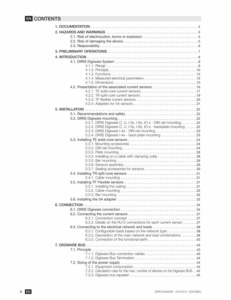
1. DOCUMENTATION . . . . . . . . . . . . . . . . . . . . . . . . . . . . . . . . . . . . . . . . . . . . . . . . . . . . . . . . . . . . .4
2. HAZARDS AND WARNINGS . . . . . . . . . . . . . . . . . . . . . . . . . . . . . . . . . . . . . . . . . . . . . . . . . . . .5
2.1. Risk of electrocution, burns or explosion . . . . . . . . . . . . . . . . . . . . . . . . . . . . . . . .5
2.2. Risk of damaging the device. . . . . . . . . . . . . . . . . . . . . . . . . . . . . . . . . . . . . . . . . . .5
2.3. Responsibility . . . . . . . . . . . . . . . . . . . . . . . . . . . . . . . . . . . . . . . . . . . . . . . . . . . . . . . .6
3. PRELIMINARY OPERATIONS . . . . . . . . . . . . . . . . . . . . . . . . . . . . . . . . . . . . . . . . . . . . . . . . . . . .7
4. INTRODUCTION . . . . . . . . . . . . . . . . . . . . . . . . . . . . . . . . . . . . . . . . . . . . . . . . . . . . . . . . . . . . . . .8
4.1. DIRIS Digiware System . . . . . . . . . . . . . . . . . . . . . . . . . . . . . . . . . . . . . . . . . . . . . . .8
4.1.1. Range . . . . . . . . . . . . . . . . . . . . . . . . . . . . . . . . . . . . . . . . . . . . . . . . . . . .9
4.1.2. Principle . . . . . . . . . . . . . . . . . . . . . . . . . . . . . . . . . . . . . . . . . . . . . . . . . .10
4.1.3. Functions . . . . . . . . . . . . . . . . . . . . . . . . . . . . . . . . . . . . . . . . . . . . . . . . .12
4.1.4. Measured electrical parameters . . . . . . . . . . . . . . . . . . . . . . . . . . . . . .13
4.1.5. Dimensions . . . . . . . . . . . . . . . . . . . . . . . . . . . . . . . . . . . . . . . . . . . . . . .15
4.2. Presentation of the associated current sensors . . . . . . . . . . . . . . . . . . . . . . . . .16
4.2.1. TE solid-core current sensors . . . . . . . . . . . . . . . . . . . . . . . . . . . . . . . .17
4.2.2. TR split-core current sensors . . . . . . . . . . . . . . . . . . . . . . . . . . . . . . . .19
4.2.3. TF flexible current sensors . . . . . . . . . . . . . . . . . . . . . . . . . . . . . . . . . .20
4.2.4. Adapters for 5A sensors . . . . . . . . . . . . . . . . . . . . . . . . . . . . . . . . . . . .21
5. INSTALLATION . . . . . . . . . . . . . . . . . . . . . . . . . . . . . . . . . . . . . . . . . . . . . . . . . . . . . . . . . . . . . . .22
5.1. Recommendations and safety . . . . . . . . . . . . . . . . . . . . . . . . . . . . . . . . . . . . . . . .22
5.2. DIRIS Digiware mounting . . . . . . . . . . . . . . . . . . . . . . . . . . . . . . . . . . . . . . . . . . . . .22
. . . . . . . . .22
. . . . . . .22
5.2.3. DIRIS Digiware I-4x - DIN rail mounting . . . . . . . . . . . . . . . . . . . . . . .23
. . . . . . . . . . . . . . . . . . . .23
5.3. Installing TE solid-core sensors . . . . . . . . . . . . . . . . . . . . . . . . . . . . . . . . . . . . . . .24
5.3.1. Mounting accessories . . . . . . . . . . . . . . . . . . . . . . . . . . . . . . . . . . . . . .24
5.3.2. DIN rail mounting . . . . . . . . . . . . . . . . . . . . . . . . . . . . . . . . . . . . . . . . . .24
5.3.3. Plate mounting . . . . . . . . . . . . . . . . . . . . . . . . . . . . . . . . . . . . . . . . . . . .26
5.3.4. Installing on a cable with clamping collar . . . . . . . . . . . . . . . . . . . . . .28
5.3.5. Bar mounting . . . . . . . . . . . . . . . . . . . . . . . . . . . . . . . . . . . . . . . . . . . . .29
. . . . . . . . . . . . . . . . . . . . . . . . . . . . . . . . . . . . . . . . .30
. . . . . . . . . . . . . . . . . . . . . . . . . . . . . .30
5.4. Installing TR split-core sensors . . . . . . . . . . . . . . . . . . . . . . . . . . . . . . . . . . . . . . .31
. . . . . . . . . . . . . . . . . . . . . . . . . . . . . . . . . . . . . . . . . . .31
5.5. Installing TF Flexible sensors . . . . . . . . . . . . . . . . . . . . . . . . . . . . . . . . . . . . . . . . .31
5.5.1. Installing the casing . . . . . . . . . . . . . . . . . . . . . . . . . . . . . . . . . . . . . . . .31
. . . . . . . . . . . . . . . . . . . . . . . . . . . . . . . . . . . . . . . . . . .32
5.5.3. Bar mounting . . . . . . . . . . . . . . . . . . . . . . . . . . . . . . . . . . . . . . . . . . . . .32
5.6. Installing the 5A adapter . . . . . . . . . . . . . . . . . . . . . . . . . . . . . . . . . . . . . . . . . . . . .32
6. CONNECTION . . . . . . . . . . . . . . . . . . . . . . . . . . . . . . . . . . . . . . . . . . . . . . . . . . . . . . . . . . . . . . . .34
6.1. DIRIS Digiware connection . . . . . . . . . . . . . . . . . . . . . . . . . . . . . . . . . . . . . . . . . . .34
6.2. Connecting the current sensors . . . . . . . . . . . . . . . . . . . . . . . . . . . . . . . . . . . . . . .37
. . . . . . . . . . . . . . . . . . . . . . . . . . . . . . . . . . . . . . .37
. . . . . . . .37
6.3. Connecting to the electrical network and loads . . . . . . . . . . . . . . . . . . . . . . . . .38
. . . . . . . . . . . . . . . . .38
. . . . . . . . .38
. . . . . . . . . . . . . . . . . . . . . . . . . . . .42
7. DIGIWARE BUS . . . . . . . . . . . . . . . . . . . . . . . . . . . . . . . . . . . . . . . . . . . . . . . . . . . . . . . . . . . . . . .43
7.1. Principle . . . . . . . . . . . . . . . . . . . . . . . . . . . . . . . . . . . . . . . . . . . . . . . . . . . . . . . . . . .43
. . . . . . . . . . . . . . . . . . . . . . . . . . . . .43
. . . . . . . . . . . . . . . . . . . . . . . . . . . . . . . . . . .44
7.2. Sizing of the power supply . . . . . . . . . . . . . . . . . . . . . . . . . . . . . . . . . . . . . . . . . . .44
. . . . . . . . . . . . . . . . . . . . . . . . . . . . . . . . . . . .44
. . .45
. . . . . . . . . . . . . . . . . . . . . . . . . . . . . . . . . . . . . .45
EN CONTENTS

3EN
8. STATUS AND AUTO-ADDRESSING LEDS . . . . . . . . . . . . . . . . . . . . . . . . . . . . . . . . . . . . . . .47
8.1. Status LEDs . . . . . . . . . . . . . . . . . . . . . . . . . . . . . . . . . . . . . . . . . . . . . . . . . . . . . . . .47
8.2. Auto-addressing . . . . . . . . . . . . . . . . . . . . . . . . . . . . . . . . . . . . . . . . . . . . . . . . . . . .47
9. COMMUNICATION . . . . . . . . . . . . . . . . . . . . . . . . . . . . . . . . . . . . . . . . . . . . . . . . . . . . . . . . . . . .49
9.1. General information . . . . . . . . . . . . . . . . . . . . . . . . . . . . . . . . . . . . . . . . . . . . . . . . .49
. . . . . . . . . . . . . . . . . . . . . . . . . . . . . . . . . .49
9.2.1. . .50
. . .50
. . . . . . . .51
9.3. Communication tables . . . . . . . . . . . . . . . . . . . . . . . . . . . . . . . . . . . . . . . . . . . . . . .51
10. CONFIGURATION . . . . . . . . . . . . . . . . . . . . . . . . . . . . . . . . . . . . . . . . . . . . . . . . . . . . . . . . . . . .52
10.1. Configuration using Easy Config . . . . . . . . . . . . . . . . . . . . . . . . . . . . . . . . . . . . .52
. . . . . . . . . . . . . . . . . . . . . . . . . . . . . . . . . . . . . . .52
. . . . . . . . . . . . . . . . . . . . . . . . . . . . . . . . . . . . . . . .54
. . . . . . . . . . . . . . . . . . . . . . . . . . . . . . . . . . . . .56
10.2. Configuration from the DIRIS Digiware D remote display . . . . . . . . . . . . . . . .56
. . . . . . . . . . . . . . . . . . . . . . . . . . . . . . . . . . . . . . . .56
11. ALARMS . . . . . . . . . . . . . . . . . . . . . . . . . . . . . . . . . . . . . . . . . . . . . . . . . . . . . . . . . . . . . . . . . . . .57
11.1. Alarms upon events . . . . . . . . . . . . . . . . . . . . . . . . . . . . . . . . . . . . . . . . . . . . . . . .57
11.1.1. Electrical parameters . . . . . . . . . . . . . . . . . . . . . . . . . . . . . . . . . . . . . .57
. . . . . .58
. . . . . . . . . . . . . . . . . . . . . . . . . . . .58
. . . . . . . . . . . . . . . . . . . . . . . . . . . . . . . . . . . . . . . . . . . .58
11.1.5. Digital inputs . . . . . . . . . . . . . . . . . . . . . . . . . . . . . . . . . . . . . . . . . . . . .58
. . . . . . . . . . . . . . . . . . . . . . . . . . . . . . . . . . . .59
11.2. System alarms . . . . . . . . . . . . . . . . . . . . . . . . . . . . . . . . . . . . . . . . . . . . . . . . . . . . .59
. . . . . . . . . . . . . . . . . . . . . . . . . . . . . . . .59
. . . . . . . . . . . .59
11.2.3. Faulty current sensor . . . . . . . . . . . . . . . . . . . . . . . . . . . . . . . . . . . . . .59
11.3. Setting up alarms . . . . . . . . . . . . . . . . . . . . . . . . . . . . . . . . . . . . . . . . . . . . . . . . . .59
11.3.1. ALARM LED on front . . . . . . . . . . . . . . . . . . . . . . . . . . . . . . . . . . . . . .59
. . . . . . . . . . . . . . . . . . . . . . . . . . . . . . . . . . . .59
. . . . . . . . . . . . . . . . . . . . . . . . . . . . . . . . . . . . . .59
. . . . . . . . . . . . . . . . . . . . . . . . . . . . . . . . . . . . . . . . . .60
11.3.5. Display and WEBVIEW . . . . . . . . . . . . . . . . . . . . . . . . . . . . . . . . . . . .60
12. FEATURES . . . . . . . . . . . . . . . . . . . . . . . . . . . . . . . . . . . . . . . . . . . . . . . . . . . . . . . . . . . . . . . . . .61
12.1. DIRIS Digiware C, U, I and IO specifications . . . . . . . . . . . . . . . . . . . . . . . . . . .61
12.1.1. Mechanical features . . . . . . . . . . . . . . . . . . . . . . . . . . . . . . . . . . . . . . .61
12.1.2. Electrical specifications . . . . . . . . . . . . . . . . . . . . . . . . . . . . . . . . . . . .61
12.1.3. Measuring characteristics . . . . . . . . . . . . . . . . . . . . . . . . . . . . . . . . . .61
. . . . . . . . . . . . . . . . . . . . . . . . . . . . . .62
. . . . . . . . . . . . . . . . . . . . . . . . . . . . . . .63
. . . . . . . . . . . . . . . . . . . . . . . . . . . . . .63
. . . . . . . . . . . . . . . . . . . . . . . . . . . . . . . . . . . . .63
. . . . . . . . . . . . . . . . . . . . . . . . . . . . . . . . . . . . . . . . . . . . . . .63
12.2. TE, TR and TF sensor characteristics . . . . . . . . . . . . . . . . . . . . . . . . . . . . . . . . .64
12.3. DIRIS D-30 and DIRIS Digiware D-40/D-50/D-70 - technical data . . . . . . . .65
12.3.1. Mechanical features . . . . . . . . . . . . . . . . . . . . . . . . . . . . . . . . . . . . . . .65
. . . . . . . . . . . . . . . . . . . .65
. . . . . . . . . . . .66
. . . . . . . . . . . .66
. . . . . . . . . . . .66
. . . . . . . . . . . . . . . . . . . . . . . . . . . . . . . . . . . .66
. . . . . . . . . . . . . . . . . . . . . . . . . . . . . . .66
13. PERFORMANCE CLASSES . . . . . . . . . . . . . . . . . . . . . . . . . . . . . . . . . . . . . . . . . . . . . . . . . . .67
13.1. Specification of the characteristics . . . . . . . . . . . . . . . . . . . . . . . . . . . . . . . . . . .67
13.2. Evaluation of the power supply quality . . . . . . . . . . . . . . . . . . . . . . . . . . . . . . . .68

4 EN
1. DOCUMENTATION
address:
www.socomec.com/en/diris-digiware

5EN
2. HAZARDS AND WARNINGS
professionals.
SOCOMEC shall not be held responsible for failure to comply with the instructions in this manual.
2.1. Risk of electrocution, burns or explosion
symbol is shownRef.
Failure to comply with the instructions of the device and this safety information can cause bodily injury,
electric shock, burns, death or damage to property.
2.2. Risk of damaging the device
symbol is shownRef.
maximum prescribed currents.
Failure to respect these precautions could cause damage to the device.

6 EN
2.3. Responsibility
of the country of installation.

7EN
3. PRELIMINARY OPERATIONS
installation.

8 EN
4. INTRODUCTION
4.1. DIRIS Digiware System
connected to the Digiware bus. This approach offers the possibility of characterising a high number of loads from a
in the N’VIEW energy management software.
* PMD: Performance Measuring and Monitoring Device in accordance with IEC 61557-12.

9EN
4.1.1. Range
Control and power supply interface (24 VDC)
DIRIS Digiware DMultipoint display
DIRIS Digiware CSystem interface*
DIRIS Dig
* if there is no multipoint display
Voltage measurement module
Current measurement module
DIRIS Digiware U-xVoltage measurement
DIRIS Digiware I-3x3 current measurement inputs
DIRIS Digiware I-4x4 current measurement inputs
DIRIS Digiware I-6x6 current measurement inputs
IO input/output modules
DIRIS Digiware IO-10Digital inputs/outputs
DIRIS Digiware IO-20Analogue inputs

10 EN
4.1.2. Principle
DIRIS Digiware U
Voltage
DIRIS Digiware C
Power supply
Digiware Bus
L1L2L3N
or
Multipoint display DIRIS Digiware D

11EN
DIRIS
Inputs/
outputs
DIRIS
DIRIS
Current sensors TE, TR or TF
12 EN
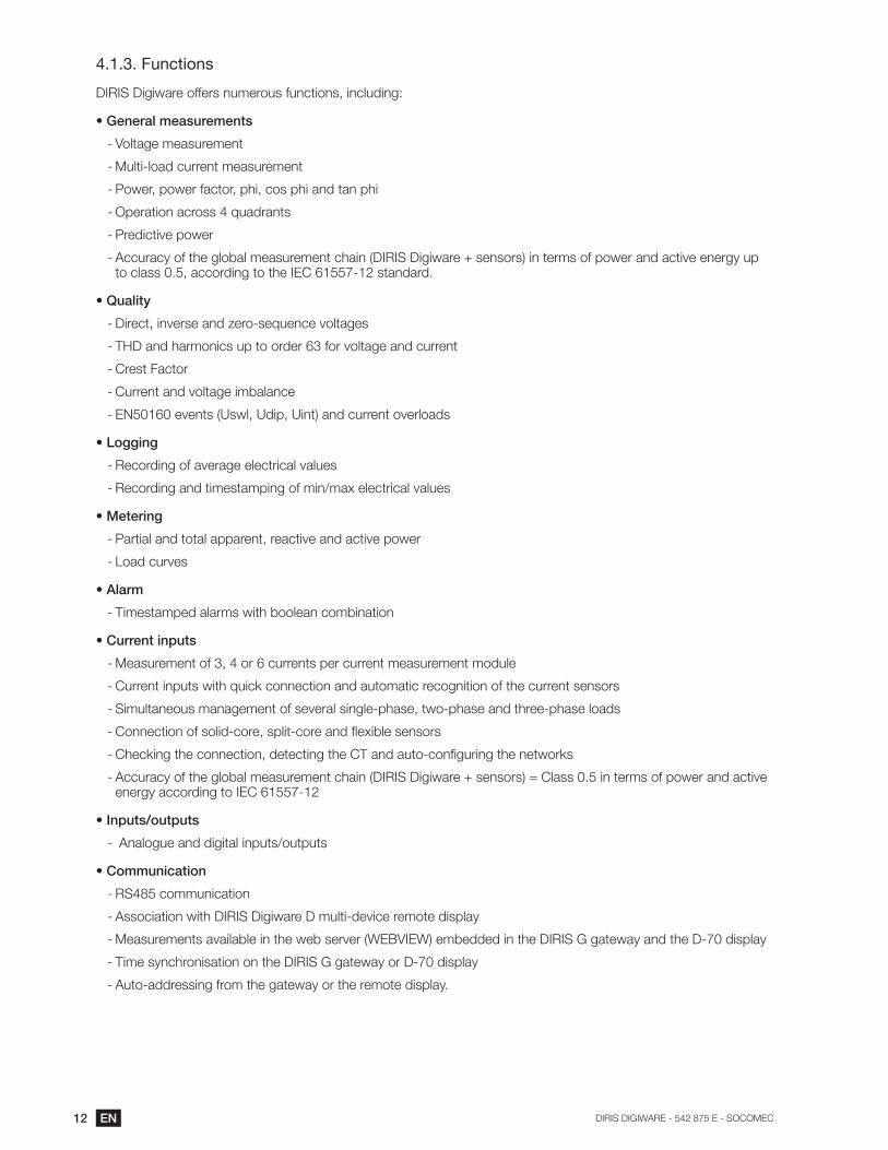
4.1.3. Functions
- Voltage measurement
- Multi-load current measurement
-
-
-
-
-
-
-
-
-
-
-
-
-
- Timestamped alarms with boolean combination
-
-
-
-
-
-
- Analogue and digital inputs/outputs
-
-
-
-
- Auto-addressing from the gateway or the remote display.

13EN
4.1.4. Measured electrical parameters
DIRIS Digiware
D-40 D-50 D-70 C-31
Function
Power supply
Communication
Digiware bus
Format
Width/Number of modules
Part number
DIRIS Digiware U
U-10 U-20 U-30
Multi-measurement
Power quality
Alarms
Thresholds
History of average values
Format
Width/Number of modules
Part number

14 EN
DIRIS Digiware I
I-30 I-31 I-33 I-35 I-43 I-45 I-60 I-61
Application Metering Monitoring Analysis Monitoring Analysis Metering
Number of current inputs 3 3 3 3 4 4
Metering
Multi-measurement
PF
Alarms
Thresholds
Number 2/2 2/2
Trends
Format
Width
Number of modules 1 1 1 1 1.5 1.5 2 2
Part number
DIRIS Digiware IO
IO-10 IO-20
Application Measuring / Monitoring / Analysis
outputs4/2 -
Number of analogue inputs - 2
Format
Width
Number of modules 1 1
Part number

15EN
4.1.5. Dimensions
4.1.5.1.
1.73
440.59
152.56
65
1.77
4590
Dimensions in/mm
I-3x
1.42
36
3.54
90
0.70
18
0.19
5
3.94
10
0
4.1.5.2.
1
25.5
5.90
15
0
2.83
72
1.06
271.76
45
0.83
21
2.28
58
1.77
45
Dimensions in/mm

16 EN
4.2. Presentation of the associated current sensors
measurement range.
DIRIS Digiware DIRIS Digiware
I-4x
DIRIS Digiware
3
TE / TR / TF
4
TE / TR / TF
6
TE / TR / TF
DI
same direction.
Connection cables for current sensors:
RJ12 connection cables
Cable length (m)
0.1 0.2 0.3 0.5 1 2 5 10+ 100
connectors*
Number of cables
Part number
Part number
Part number
Part number
Part number
Part number
Part number
Part number Part number
1 - - - - - -
3 - - -
4 - - -
- - -

17EN
4.2.1. TE solid-core current sensors
The TE solid-core current sensors are used to set up measurement points in a new or existing installation. They are
measurement chain is guaranteed.
4.2.1.1. Range
TE-18 TE-18 TE-25 TE-35 TE-45 TE-55
Pitch 25 mm 35 mm 45 mm 55 mm
Nominal current range In
Maximum l
Part number
TE-90
Pitch
Nominal current range In
Maximum l
Part number

18 EN
4.2.1.2. Dimensions
L H
P
W
L H
L
W
P
T
H
Dimensions in/mm TE-18 TE-25 TE-35 TE-45 TE-55
Pitch0.71 0.98
251.3735
1.7745
2.1655
LxHxD1.10 x 0.79 x 1.77 0.98 x 1.28 x 2.56 1.37 x 1.28 x 2.79 1.77 x 1.28 x 3.38 2.16 x 1.28 x 3.93
Aperture (W)
Diameter 0.33 0.53 x 0.5313.5 x 13.5
0.82 x 0.8221 x 21
1.22 x 1.2231 x 31
1.61 x 1.6141 x 41
(T)- 0.69 0.69 0.77
19.50.8521.5
3.54
900.08
2.2
0.77
19.7
1.42
36
=
==
= 2.52 / 644.96
126
0.97
24.6
Dimensions in/mm TE-90

19EN
4.2.2. TR split-core current sensors
The TR split-core current sensors are used to set up measurement points in a new or existing installation without
accuracy of the measurement chain is guaranteed.
4.2.2.1. Range
TR-10 TR-16 TR-24 TR-36
Aperture
Nominal current range In
Maximum l
Part number
4.2.2.2. Dimensions
PA
L
Ø W
C
B
H
Dimensions in/mm TR-10 TR-16 TR-24 TR-36
LxHxD0.98 x 1.54 x 2.79 1.18 x 1.65 x 2.91 1.77 x 1.73 x 3.74
45 x 44 x 952.24 x 1.65 x 4.37
W0.39 0.63 0.94
241.42
A2.28 2.40 2.83 3.23
B0.5714.5
0.7519
0.8722
0.8722
C1.02 1.22
311.3434
1.59

20 EN
4.2.3.
particularly suitable for adding measuring points in existing installations and for test campaigns.
4.2.3.1. Range
TF-55 TF-120 TF-300
Loop length 55 mm
Nominal current range In
Part number
4.2.3.2. Dimensions
0.71
18
3.34
85
E
p Ø
L L
0.71
18
3.34
85
1.49
38
E
p
Ø
L L
Dimensions in/mm TF-55 TF-120 TF-300
Diameter 2.1655
4.72 11.81
p7.16 14.80 37.08
942
T0.23 0.43
110.4311
L59.05

21EN
4.2.4. Adapters for 5A sensors
The adapter enables the use of a standard sensor supplying a 1A or 5A current to the secondary sensor. When this
4.2.4.1. Range
5A adapter
I nom.
I max.
Part number
4.2.4.2. Dimensions
L H
P
W
L H
Dimensions in/mm 5A adapter
LxHxD1.10 x 0.79 x 1.77
Aperture (W)
Diameter 0.33

22 EN
5. INSTALLATION
5.1. Recommendations and safety
5.2. DIRIS Digiware mounting
5.2.1. DIRIS Digiware C, U, I-3x, I-6x, IO-x - DIN rail-mounting
1
2
1.3
8 in
35
mm
0.29 or 0.59 in
5.2.2. DIRIS Digiware C, U, I-3x, I-6x, IO-x - backplate-mounting
0.19 in5 mm
3.9
4 in
Type of screw: M4
Washer diameter

23EN
5.2.3. DIRIS Digiware I-4x - DIN rail mounting
DIRIS Digiware I-4x mounting DIRIS Digiware I-4x dismounting
1.77
45
1
2
Two mounting positions are possible:Position I (factory assembly): for 15mm rail.Position II: for 7.5mm rail
Position I
Position II
1
2
Mounting in Position II
3
1
3
1
2
5.2.4. DIRIS Digiware I-4x - back-plate mounting
1
Mounting of the brackets on the top and bottom of the module.
2
6.8
1 in
Type of screw: M4
Washer diameter
2
Type of sc
Washer dia

24 EN
5.3. Installing TE solid-core sensors
5.3.1. Mounting accessories
The list of mounting accessories supplied with the sensors are listed below:
Part number
PitchDIN rail and plate
mountingDIN rail mounting Plate mounting Busbar mounting
TE-18 18 mm x 1
TE-25 25 mm x 2 x 4
TE-35 35 mm x 2 x 4 x 2
TE-45 45 mm x 2 x 4 x 2
TE-55 55 mm x 2 x 4 x 2
TE-90 90 mm x 2
5.3.2. DIN rail mounting
TE-18 -> TE-55

25EN
TE-90
2
1
oror
26 EN
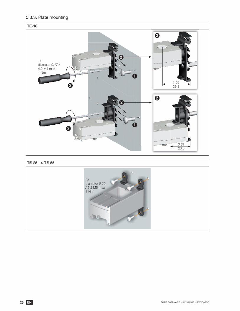
5.3.3. Plate mounting
TE-18
1x
0.17 /
0.81
1.05
1
1
2
2
2
2
3
3
TE-25 - > TE-55
4x
0.20
/

27EN
TE-90
2
1
x6
diameter 0.20
diameter 5.2

28 EN
5.3.4. Installing on a cable with clamping collar
TE-18 TE-25 - > TE-55
2
3
1
TE-90
2
1
I

29EN
5.3.5. Bar mounting
TE-35 - > TE-55
A
A A
C
B Installation options:
A+B, A+C
key
B
C
TE-90
or
Tighten the jaws on both
sides of the cable by apply-
ing pressure.
The jaws must be per-
pendicular to the holding
notches.
II
21

30 EN
5.3.6. Sensors assembly
TE-18 TE-25 - > TE-55 TE-35 - > TE-55
1.42
Staggered assembly
2x
Linear assembly
1x
Staggered assembly
Mounting accessories for sensor combination:
Part number
Linear assembly Staggered assembly
These accessories must be ordered separately.
5.3.7. Sealing accessories for sensors
21
Part number
Sealing case for terminal
These accessories must be ordered separately.

31EN
5.4. Installing TR split-core sensors
5.4.1. Cable mounting
144
33
2
K
L
III
LL
I
5.5. Installing TF Flexible sensors
5.5.1. Installing the casing
DIN rail Plate Frame
1.38 35
0.29 or 0.59
1
2
Washer
max.
0.195
3.9
4

32 EN
5.5.2. Cable mounting
=
=
=
=
5.5.3. Bar mounting
=
=
=
=
5.6. Installing the 5A adapter
4
3
1
25A secondary current transformer

33EN

34 EN
6. CONNECTION
6.1. DIRIS Digiware connection
RS485 line polarisation
Earth must not be used in a neutral IT system
RS
485
12
ON
I-3x
3x current sensor inputs
I-3x
3x current sensor
DIRIS
Digiware U
Voltage
measurement
DIRIS
Digiware C
Power supply
Digiware Bus
DIRIS
Multipoint display DIRIS Digiware D
Power supply
Nm max.2 2 solid
2 2
CommunicationRS485 Modbus
Nm max.2 2 solid
2 2
Voltage input U
2 2 solid2 2
L1
L2
L3
N
us
max.
or
L1
L2
L3
N
age input U
2 2 solid2

35EN
I-4x
4x current sensor inputs
I-6x
6x current sensor inputs
Digiware Bus Termination
DIRIS
DIRIS
DIRIS
Inputs/
outputs
2x digital outputs
Nm max.2 2 solid2 2
2x digital inputs
Nm max.2 2 solid2 2
IO-104x digital inputs
2x digital outputs
IO-202x analogue inputs
2 2 solid2 2
local single-point display
4x
2xOUT
IN

36 EN
Description of the terminals
DIRIS Digiware D-40
NC
RS
485
Dig
iwar
e
LIYCY-CY
SLAVE
24 V
SU
PP
LY
24 VDC(20 W max)
Digiware Bus
NC
RS
485
Dig
iwar
e
LIYCY-CY
MASTER
24 VDC(20 W max)
Ethe
rnet
24 V
SU
PP
LY
Digiware Bus
Ethernet
DIRIS Digiware C-31
24 V
SU
PP
LYR
S4
85NC
12
ON D
IGIW
AR
E B
US
RJ4
5
24 V
SU
PP
LYR
S4
85NC
LIY
CY-C
Y
12
ON
24 V
SU
PP
LYR
S4
85NC
12
ON
Digiware BUSPower supply Communication Line polarisation
DIRIS Digiware C-32 DIRIS Digiware U DIRIS Digiware I-3x
DIG
IWA
RE
BU
S
RJ45 IN
OU
T
24 V
SU
PP
LY
Digiware BUSPower supply
V1
VN
V3
V2
DIG
IWA
RE
BU
S
RJ4
5
Digiware BUSVoltage measurement
I 01
I 02
I 03
RJ1
2
DIG
IWA
RE
BU
S
RJ4
5
Digiware BUSCurrent measurement(**)
DIRIS Digiware I-4x DIRIS Digiware I-6x
I 01
I 02
I 03
I 04
RJ1
2
Current measurement(**)
DIG
IWA
RE
BU
S
RJ4
5
Digiware BUS
INP
UT
1
CO
M
2
12 V
d.c
.(1m
A m
ax)
Inputs
OU
TP
UT
250 V
a.c
.(1A
max)
21
11
13
23
OutputsRJ9 for DIRIS D-30
(Self-powered and
RJ9
DIG
IWA
RE
BU
S
RJ4
5Digiware BUSCurrent
measurement(**)
I 04
I 05
I 06
I 01
I 02
I 03
RJ1
2
RJ1
2
DIRIS Digiware IO-10 DIRIS Digiware IO-20
13
14
23
24
12-48VDC
12-24VAC
50mA
12VDC
IN1
COM-
IN2
IN3
IN4
OUT1
OUT2
OUTPUT
INPUT
DIG
IWA
RE
BU
S
RJ4
5
Digiware BUS Inputs
DIG
IWA
RE
BU
S
RJ4
5
Digiware BUS

37EN
6.2. Connecting the current sensors
6.2.1. Connection concept
DIRIS Digiware
I-3x
DIRIS Digiware
I-4x
DIRIS Digiware
3
TE / TR / TF
4
TE / TR / TF
6
TE / TR / TF
DI
I-
same direction.
6.2.2. Details on the RJ12 connections for each current sensor
TE TR TF
cable for current sensors
PMD
DIRIS B
DIRIS Digiware
TE-18 to TE-55
TE-90
current sensors
Do not bring into contact
PMD
DIRIS B
DIRIS Digiware
cable for current sensors
cabcurrent s
1
3
2
PMD
DIRIS B
DIRIS Digiware
38 EN
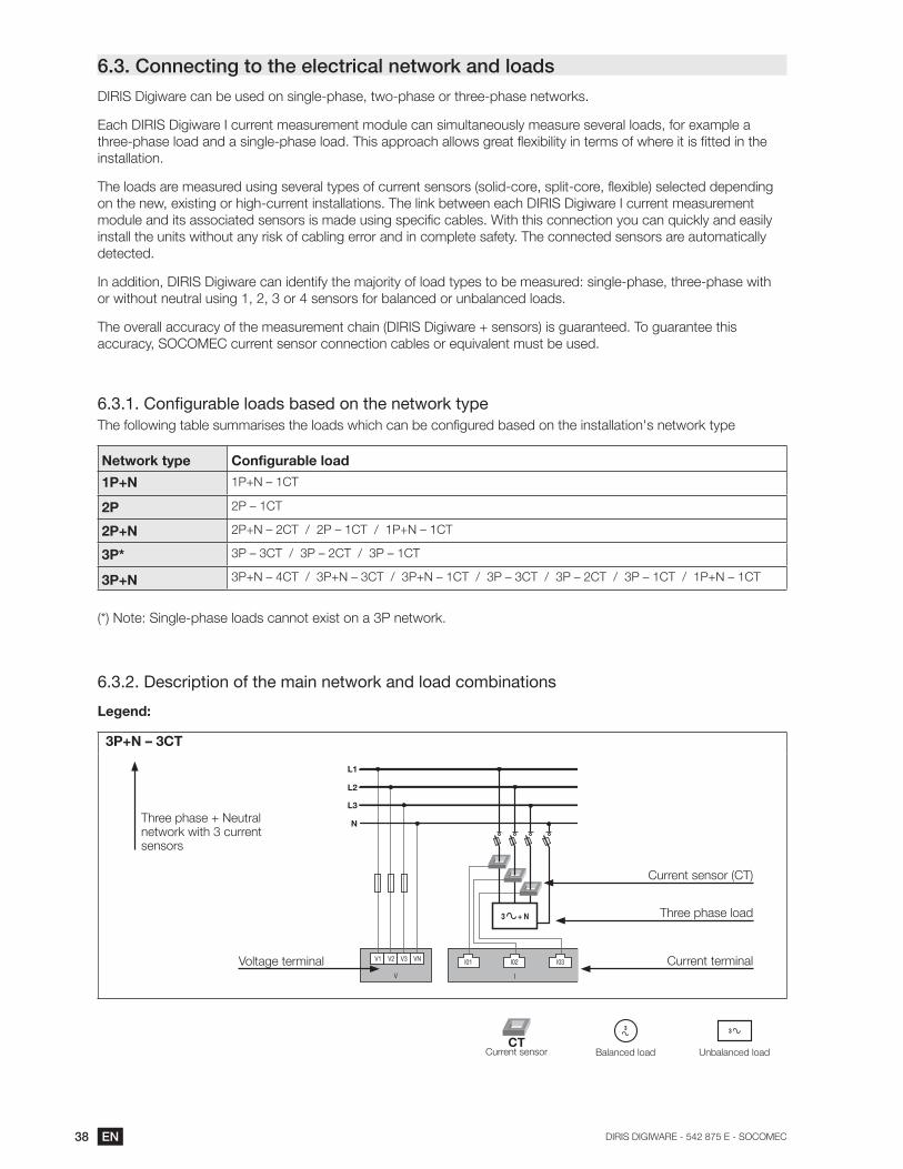
6.3. Connecting to the electrical network and loads
installation.
detected.
6.3.1.
Network type Configurable load
1P+N
2P
2P+N
3P*
3P+N
6.3.2. Description of the main network and load combinations
Legend:
3P+N – 3CT
N
V1 V2 V3 VN
V I
L1
L2
L3
I01 I02 I03
3 + N Three phase load
Voltage terminal
sensors
CT
3
Balanced load
3

39EN
DIRIS Digiware I-3x
Three-phase + Neutral
3P+N - 3CT
Three-phase
3P – 3CT
N
V1 V2 V3 VN
V I
L1
L2
L3
I01 I02 I03
3 + N
V1 V2 V3 VN
V I
L1
L2
L3
I01 I02 I03
3
Three-phase
3P – 2CT & 3P – 1CT
Three-phase
3P – 1CT (x3)
V1 V2 V3 VN
V I
L1
L2
L3
I01 I02 I03
3 3
V1 V2 V3 VN
V I
L1
L2
L3
333
I01 I02 I03
Two-phase
2P – 1CT (x3) Single-phase
1P+N – 1CT (x3)
I
V1 V2 V3 VN
V
L1
L2
I01 I02 I03
222
V I
V1 V2 V3 VN
L1
N
I02 I03I01
1 1 1

40 EN
DIRIS Digiware I-4x
Three-phase + Neutral
3P+N – 4CT
Three-phase + Neutral
3P+N – 3CT & 3P – 1CT
I
I01 I02 I03 I04
N
V1 V2 V3 VN
V
L1
L2
L3
3 + N
N
V1 V2 V3 VN
V I
L1
L2
L3
3
I01 I02 I03 I04
3 + N
Three-phase + Neutral 3P+N – 3CT & 1P+N – 1CT Three-phase 3P – 3CT & 3P – 1CT
N
V1 V2 V3 VN
V I
L1
L2
L3
I01 I02 I03 I04
3 + N 1
V1 V2 V3 VN
V I
L1
L2
L3
3
I01 I02 I03 I04
3
Three-phase 3P – 2CT (x2) Three-phase 3P – 1CT (x4)
V1 V2 V3 VN
V I
L1
L2
L3
I01 I02 I03 I04
3 3
V1 V2 V3 VN
V I
L1
L2
L3
3333
I01 I02 I03 I04

41EN
Two-phase + Neutral 2P+N – 2CT (x2) Two-phase2P – 1CT (x4)
V1 V2 V3 VN
V I
L1
L2
N
I01 I02 I03 I04
2 + N2 + N
I
V1 V2 V3 VN
V
L1
L2
I01 I02 I03 I04
2222
Single-phase1P+N – 1CT (x4)
V I
V1 V2 V3 VN
L1
N
I02 I03I01 I04
1 1 1 1
Three-phase
3P – 3CT + 3P – 1CT (x3)
333
V1 V2 V3 VN
V I
L1
L2
L3
I01 I02 I03I04 I05 I06
3
I01 I02 I03

42 EN
Single-phase 1P+N – 1CT (x6)
V1 V2 V3 VN
V I
L1
N
I01 I02 I03I04 I05 I06
I01 I02 I03
1 1 1 1 1 1
Notes relating to connections:
The
3P – 2CT
3P – 1CT
6.3.3. Connection of the functional earth
It is recommended that the functional earth is connected to guarantee optimum measuring accuracy and better
in a neutral IT system.

43EN
7. DIGIWARE BUS
7.1. Principle
or
U measurement module
System interface module
Display I measurement modules
DIRIS Digiware I-3xDIRIS Digiware I-4x
Measurement module IO
Digiware Bus Termination
or
Digiware Bus Termination
Digiware Bus
DIRIS Digiware is a system comprising the following elements:
7.1.1. Digiware Bus connection cables
Length (m) Quantity Part number
1
1
1
1 1
2 1
5 1
1

44 EN
7.1.2. Digiware Bus Termination
Quantity Part number
1
system interface module.
7.2. Sizing of the power supply
module.
NC
RS485
Supply
24VDC
24VDC
12
ON
Modular format
7.2.1. Equipment consumption
Device Power supplied (W) Power consumed (W)
Power supply
15
Cables
1.5
System interface
2
2
Module voltage
Module current
DIRIS Digiware I-3x .52
DIRIS Digiware I-4x 1.125
.
.5
Repeater
1.5
Single-point display
2

45EN
7.2.2. Calculation rules for the max. number of devices on the Digiware BUS
Size with P15 power supply (ref: 4829 0120) delivering 15 W
and
Total power = 14.62 W
or
.
Size with a 24 VDC power supply delivering a maximum of 20 W
and
Total power = 19.82 W
or
.
7.2.3. Digiware bus repeater
DIRIS Digiware C-32 repeater
Part number

46 EN
Digiware Bus
DIRIS Digiware D
supply supply
Digiware Bus
I-3x
I-4x
I-3x
I-4x
DIRIS Digiware C-32
Sup
ply
24V
DC
24VDC
DIG
IWA
RE
BU
S
RJ45 IN
OU
T

47EN
8. STATUS AND AUTO-ADDRESSING LEDS
8.1. Status LEDs
The addressing button is used to automatically assign a Modbus address from the gateway.
Power supply
Alarm
Metrology
Addressing button
LED state Fixed Pulse
ONIn operation
Modbus control to identify the 1 second to start-up
ALARM if there is a system alarm at the
At least one system alarm is 1 second to start-up
COMAddressing problem. 1 second to start-up and when a
change of state in all of the inputs
logical mode
metrological pulse weight
in pulse counter mode
8.2. Auto-addressing
Mode 1 - Auto-detection and automatic addressing
Mode 2 - Auto-detection and address selection

48 EN
Description of mode 1 Flashing LED LED continuously on
DIRIS Digiware
Press 3 sec.
Press 3 sec.4a 4b
7 7
5a 5b
3 3
GatewayDIRIS G
Press 3 sec. 1
Press 3 sec. 6
2
7
3
addressing.
exchange of data is possible at this time.

49EN
9. COMMUNICATION
9.1. General information
Example of architecture in combination with the DIRIS G gateway:
Digiware Bus
WEBVIEW
Ethernet
DIRIS G DIRIS B DIRIS DIRIS B
Digiware Bus Termination
9.2.
out in the paragraphs below.
Digiware Bus
Ethernet
DIRIS G DIRIS B
Digiware Bus Termination

50 EN
9.2.1.
A termination must be added at the end of the Digiware bus.
Ethernet
DIRIS GDIRIS
DIRIS B
Digiware Bus Termination
Digiware Bus
9.2.2.
A termination must be added at the end of the Digiware bus.
Digiware Bus
Digiware Bus Termination
Ethernet
DIRIS BDIRIS
Digiware Bus

51EN
9.2.3.
Digiware bus.
A termination must be added at the end of the Digiware bus.
Digiware Bus Termination
Digiware BusDig
9.3. Communication tables
The communication tables and associated explanations can be
found on the documentations page for DIRIS Digiware on the
www.socomec.com/en/diris-digiware
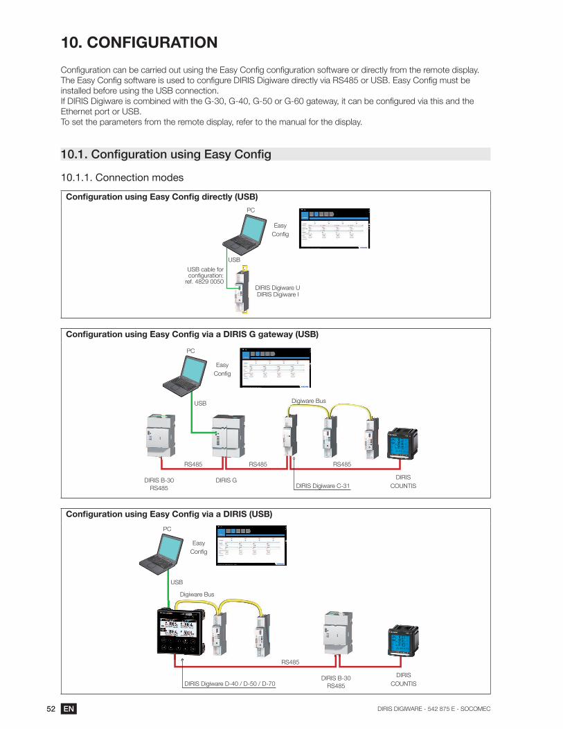
52 EN
10. CONFIGURATION
10.1.
10.1.1. Connection modes
DIRIS Digiware I
Easy
DIRIS GDIRIS
Easy
Digiware Bus
Digiware Bus
Easy
DIRIS
Digiware Bus

53EN
DIRIS GDIRIS
Ethernet
Easy
Digiware Bus
Digiware Bus
Ethernet
Easy
DIRIS
Digiware Bus
54 EN
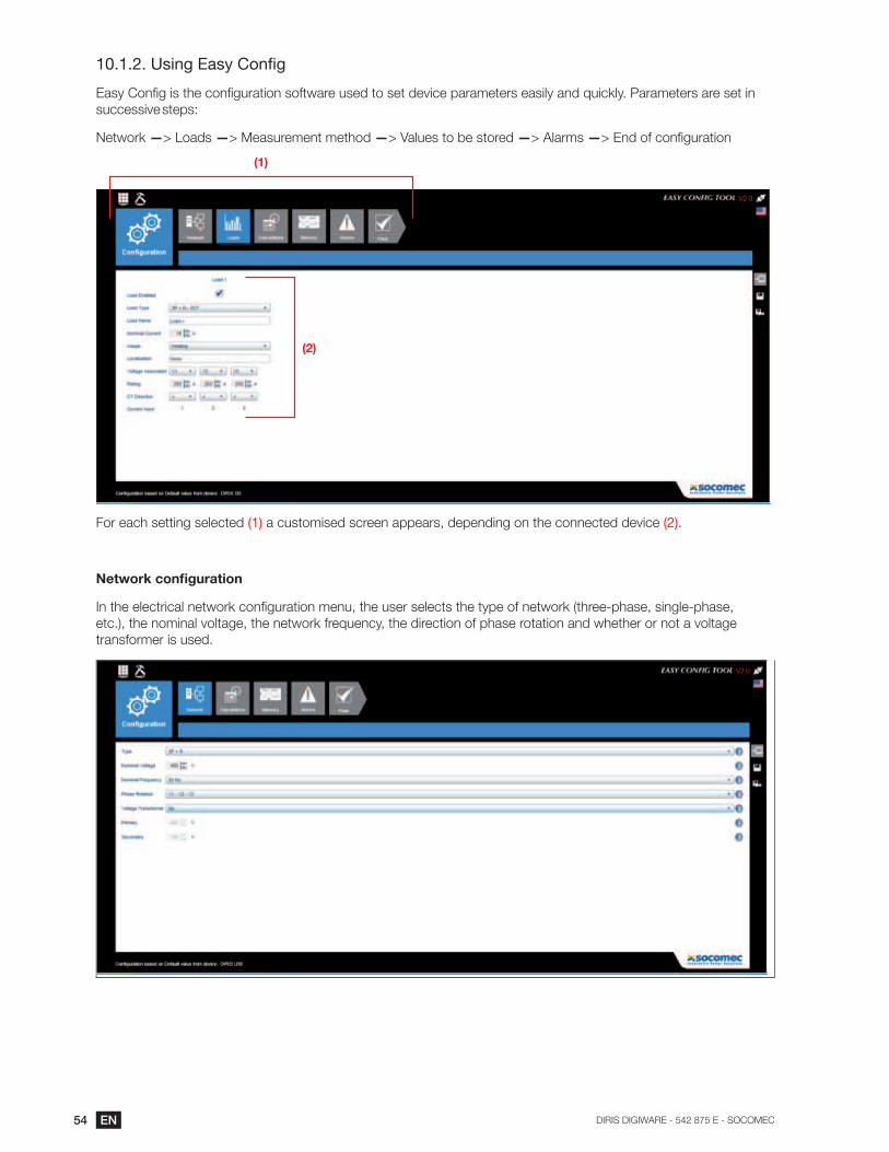
10.1.2.
—> Loads —> Measurement method —> Values to be stored —> Alarms —
(1)
(2)
For each setting selected (1) (2).
transformer is used.

55EN
Calculation method
Alarms
more details.

56 EN
10.1.3. Synchronising devices
The screen below shows how to set the time from the DIRIS G gateway. The time setting is done from an SNTP
schedule.
10.2.
10.2.1. Connection mode
Bus)
Display DIRIS DIRIS
Digiware I
Digiware Bus
Refer to the manual for the DIRIS Digiware D display for more details.

57EN
11. ALARMS
11.1. Alarms upon events
11.1.1. Electrical parameters
Selection of the hysteresis and high/low threshold.
Setting a time delay at the start and end of the alarm.
-
-
-

58 EN
11.1.2. Voltage and current unbalance (in a three-phase network)
Selection of the hysteresis and high/low threshold
Setting a time delay at the start and end of the alarm
11.1.3. EN 50160 voltage quality events
11.1.4. Consumption
11.1.5. Digital inputs
Alarm upon change of status of a digital input
Setting a time delay at the start and end of the alarm

59EN
11.1.6. Combination of alarms
11.2. System alarms
11.2.1. Current/voltage connection
11.2.2. Incorrect direction of rotation (three-phase network)
11.2.3. Faulty current sensor
Alarm for detecting the absence of a current sensor
11.3. Setting up alarms
software.
11.3.1. ALARM LED on front
11.3.2. Activation of an output
11.3.3. Activation of an input

60 EN
11.3.4. RS485 Modbus
11.3.5. Display and WEBVIEW
Information on the alarms with timestamping

61EN
12. FEATURES
12.1.
12.1.1. Mechanical features
DIN-rail mounting module and base
Front panel protection index
12.1.2.
DIRIS Digiware C-31
P15 power supply
12.1.3. Measuring characteristics
Measurement accuracy
AccuracyPMD DD classification in
Measuring energy and power
Power factor measurement
Accuracy
Voltage measurement - DIRIS Digiware U
Single-phase/ Two-phase / Two-phase with neutral / Three-phase / Three-phase with neutral
Input consumption

62 EN
Current measurement - DIRIS Digiware I
Number of current inputs
Associated current sensors
Accuracy of current measurement
Bus with bus termination for the last module
Inputs - DIRIS Digiware I-4x
Number of inputs 2
Type / Power supply
Input functions
Outputs - DIRIS Digiware I-4x
Number of outputs 2
Relay type
Functioncontrolled status
Digital inputs/outputs- DIRIS Digiware IO-10
Number of inputs 4
Type / Power supply
Input functions Logical status
Number of outputs 2
Type
Remote control
Analogue inputs - DIRIS Digiware IO-20
Number of inputs 2
Type / Power supply
Accuracy
Function
12.1.4.
Digiware BUS
Function
63EN
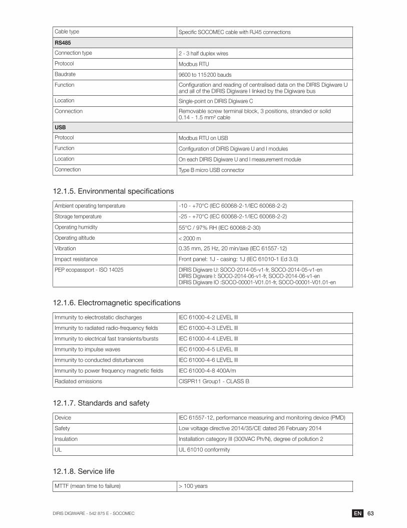
RS485
2 - 3 half duplex wires
Protocol
Baudrate
Function
Location
USB
Protocol
Function
Location
12.1.5.
Ambient operating temperature
Storage temperature
Vibration
Impact resistance
12.1.6.
Immunity to electrostatic discharges
Immunity to electrical fast transients/bursts
Immunity to conducted disturbances
Radiated emissions
12.1.7. Standards and safety
Safety
Insulation
12.1.8. Service life

64 EN
12.2. TE, TR and TF sensor characteristics
TE - solid-core sensor TE-18 to TE-55
Model TE-18 TE-18 TE-25 TE-35 TE-45 TE-55
24 192
24 24
Measurement category
Protection degree
Storage temperature
Altitude
TE - solid-core sensor TE-90
Model TE-90
Nominal current range In
Max. current
Weight
Measurement category
Protection degree
Storage temperature
Altitude
TR - Split-core sensor
Model TR-10 TR-16 TR-24 TR-36
211 311
65EN
Measurement category
Protection degree
Storage temperature
Altitude
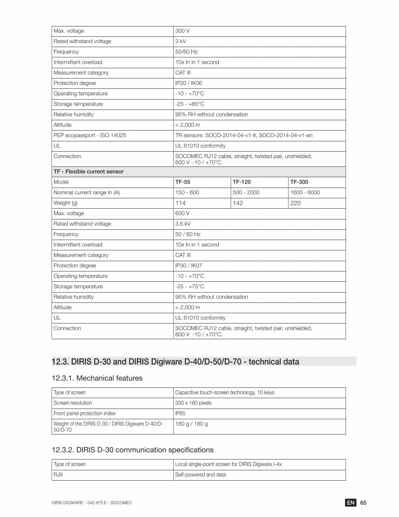
TF - Flexible current sensor
Model TF-55 TF-120 TF-300
114 142
Measurement category
Protection degree
Storage temperature
Altitude
12.3.
12.3.1. Mechanical features
Type of screen
Screen resolution
Front panel protection index
12.3.2.
Type of screen Local single-point screen for DIRIS Digiware I-4x
Self-powered and data

66 EN
12.3.3.
Type of screen Multipoint remote screen
12.3.4.
Type of screen Multipoint remote screen
12.3.5.
Type of screen Multipoint remote screen
Gateway function:
SNTP protocol
Sends email notifications from the display.
12.3.6.
Power supply
Power consumption
12.3.7.
Storage temperature
Installation category - degree of pollution

67EN
13. PERFORMANCE CLASSES
Temperature
energy
1 in combination with TR split-core sensors
13.1.
Symbol Function
Overall operating performance class
sensors* (TE, TR, TF) in compliance with IEC 61557-12
Measurement range
Pa
1 with TR sensors
A V
SA V
1 with TR sensors
Ea
1 with TR sensors
ErA V
EapA V
1 with TR sensors
f
1 with TR sensors
INc 1 with TE or TF sensors2 with TR sensors
PFA V
1 with TR sensors leading
- -
-
-
-
-
Voltage phase and amplitude unbalance (Lp-Lg or -
1
Voltage harmonics 1 -
1
Ih 1 -
- -

68 EN
13.2. Evaluation of the power supply quality
Symbol Function
Overall operating performance class
sensors (TE, TR, TF) in compliance with IEC 61557-12
Measurement range
f
1 with TR sensors
INc 1 with solid-core TE or TF sensors2 with TR sensors
- -
-
-
-
-
Voltage phase and amplitude unbalance (Lp-Lg or -
Voltage harmonics 1 -
Ih 1 -
- -

69EN

542 875 E
CORPORATE HQ CONTACT:
SOCOMEC SAS
1-4 RUE DE WESTHOUSE
67235 BENFELD, FRANCE
www.socomec.com


