02/07/22 Intro and VXI 1 Intended to provide: High-density platform through shared resources Precise tim ing coordination betw een instrum ents Longersystem supportthrough m ulti-vendorsolutions C apability to addresshigh-perform ance requirem ents A Proven High Perform ance Instrum entArchitecture VXIbus (VM EbusExtensions forInstrum entation)(IEEE-STD-1155) Developed in 1987 to provide a standard m odularopen industry architecture forinstrum entation. VXI O verview
Transcript
04/10/23Intro and VXI 1
Intended to provide: High-density platform through shared resources Precise timing coordination between instruments Longer system support through multi-vendor solutions Capability to address high-performance requirements
A Proven High Performance Instrument Architecture VXIbus (VMEbus Extensions for Instrumentation) (IEEE-STD-1155)
Developed in 1987 to provide a standard modular open industry
architecture for instrumentation.
VXI Overview
04/10/23Intro and VXI 2
VXIbus Basics
A VXIbus system or subsystem consists of a mainframe, VXIbus devices, a slot 0 card, resource manager, and host controller.
VXIbus Devices: Typically message-based or register-based devices
VXIbus Mainframe: Houses the VXIbus devices (4,5,6 and 13 slot mainframes) Contains the power and cooling mechanism Contains the communication backplane Slot 0 Interface: Backplane management and (Shared) System Clock sources Arbitration Remote control through various comm interfaces Resource Manager: Configures the modules for proper operation at
power-up and reset Host Controller: Controls the operations of the ATE system and environment
04/10/23Intro and VXI 3
Four additional power supply voltages The local bus Analog sumbus TTL and ECL trigger buses 10 MHz differential ECL clock signal
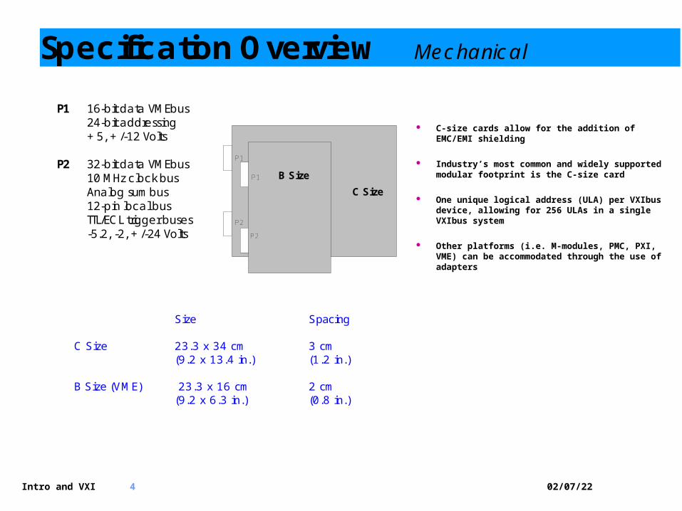
The VXIbus specifies has two primary backplane connectors (P1 and P2). The P1 connector, (mandatory in VME or VXIbus), carries the data transfer bus. The P2 connector, expands the data transfer bus to a full 32-bit size, and adds:
Specification Overview Electrical
04/10/23Intro and VXI 4
P1 16-bit data VMEbus
24-bit addressing +5, +/-12 Volts
P2 32-bit data VMEbus 10 MHz clock bus Analog sumbus 12-pin local bus TTL/ECL trigger buses -5.2, -2, +/-24 Volts
C-size cards allow for the addition of EMC/EMI shielding
Industry’s most common and widely supported modular footprint is the C-size card
One unique logical address (ULA) per VXIbus device, allowing for 256 ULAs in a single VXIbus system
Other platforms (i.e. M-modules, PMC, PXI, VME) can be accommodated through the use of adapters
C Size
B Size
P1
P1
P2
P2
Size Spacing C Size 23.3 x 34 cm 3 cm (9.2 x 13.4 in.) (1.2 in.) B Size (VME) 23.3 x 16 cm 2 cm (9.2 x 6.3 in.) (0.8 in.)
The VXIbus mainframe is specified for power delivered. Each power supply has a peak DC current delivery and peak-to-peak dynamic current delivery.
By calculating the total power and current of modules within
the system, the total system power can be determined. The VXIbus mainframe specifies worst-case pressure drops
vs. airflow rate through a single slot. Each instrument must specify airflow and back pressure
required (normally for a 10oC rise in temperature). System cooling can be determined by plotting on a mainframe graph.
Optimize mainframe for cooling/power. Remember that more cooling extends component life.
Volts Qty Pins Power P1 P1 P1
Specification Overview Power & Cooling
04/10/23Intro and VXI 6
Specification Overview Power & Cooling
Power - VXI added power supplies +5 V DC - Main power source for most VXI
Instruments
+/- 12 V DC - Used for powering analog devices,
communications interfaces
+/- 24 V DC - Used for powering analog signal
sources (20V into hi Z) plus +/- 15 V regulators\
-5.2 V DC - For ECL devices
-2 V DC - Used for the termination of ECL loads
+5 V DC STDBY - Standby for memory / power lost
04/10/23Intro and VXI 7
The VXIbus specifies radiated and conducted EMC limits for both generation and susceptibility. This ensures that modules containing sensitive electronic circuits perform to expectations without interference from any other module operating in the system.
Specification Overview EMI/EMC
04/10/23Intro and VXI 8
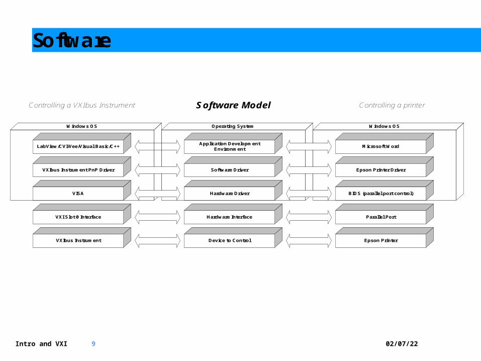
Communicating with the VXIbus Instruments Hardware Communications: External computer to VXIbus chassis interface:
GPIB/VXI, MXI2/VXI, USB 2.0/VXI, Firewire/VXI, LAN/VXI, etc. PC-platform and OS independent
Embedded computer:
Resides in the slot 0, generally PC-based
Two main ways to communicate with a VXIbus device: Message-based devices
The message-based device has a Word Serial Protocol to allow ASCII-level communications. SCPI builds upon this.
Register-based devices
The register-based device communicates only through register reads and writes. Configuration is controlled by VXIbus-defined configuration registers but programmed through device dependent registers. VXI plug&play drivers use the VISA protocol to provide an API that is communications agnostic.
· Upper 16 kB of A16 space reserved for VXI configuration space
· 64 B per device
· 8-bit logical address specifies base address for each device
•TTL0 – DMM measure complete, close next relay channel
•TTL1 – Relay has settled, initiate DMM measurement
• Highly deterministic asynchronous handshaking significantly reduces test time by removing any dependency on host controller to manage the switch/measure sequencing
04/10/23Intro and VXI 11
Connectors Mechanical
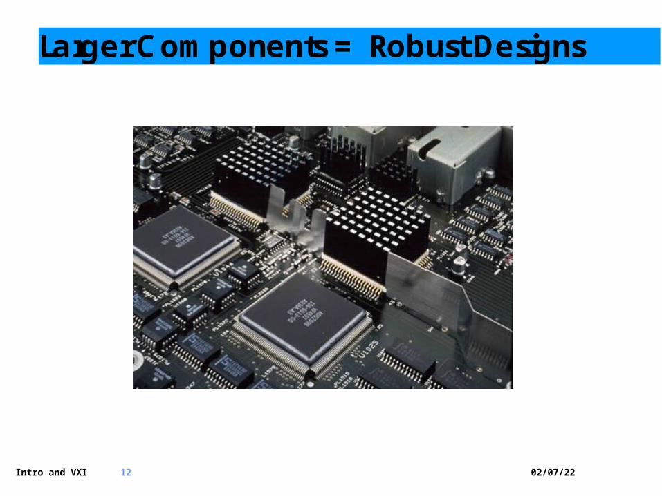
• 1.2” Center spacing permits use of larger components, and more robust, ergonomically friendly connectors
6 x 6 RF matrix (18 GHz) in two slots
(20) SPST 30 A relays in one slot
(144) 2-wire crosspoint, 2 A switched relays in ½ slot
04/10/23Intro and VXI 12
Larger Components = Robust Designs
04/10/23Intro and VXI 13
Flexible Remote Control
The VXIbus can attribute its longevity in part to its ability to adapt to newer communication bus architectures for remote control without affecting backward compatibility.
GPIB-VXI
PCI-VXI
IEEE1394-VXI
USB 2.0-VXI
LXI-VXI
PCIe-VXI
04/10/23Intro and VXI 14
A Platform that Unites
VXI adapts many platforms via carriers in a single mainframe Can eliminate need for multiple mainframes within a system
PXI
PXIVXI
VXI
VME
04/10/23Intro and VXI 15
Module within a module platform
The VXIbus specification permits multiple ‘sub-modules’. Each can be treated as an independent instrument with discrete
logical address. Enables very high-density, flexible system
(80) SPST, 300 V/2 A relaysPrototyping breadboard12 x 24, 300 V/2 A matrix (two modules)(10) SP4T 50 Ohm Coaxial Trees, 1.3 GHz(12) SPDT, 16 A, 300 W dc relays(8) SPDT, 20 A, 600 W dc relays(2) 1 x 24 1000 V multiplexers
5U
04/10/23Intro and VXI 17
Brings all of the instrument and switching I/O out to a common interface panel
ICA= Interface Connector Assembly Or Receiver
Permits use of multiple adapters to map into the I/O of a unit being tested
ITA= Interface Test Adapter Or ID = Interface Device
Interfacing DUTs to VXI Instrumentation
A Test Receiver…
04/10/23Intro and VXI 18
When to use a receiver
When using a common tester to test…
Multiple products
Multiple assembly levels of the same product Assembled unit vs. PCB LRU vs. SRU in military terms
To minimize failures of instrument contacts
Reduces wear/tear directly on instrument
Receiver contacts have higher insertion counts/easier to repair
04/10/23Intro and VXI 19
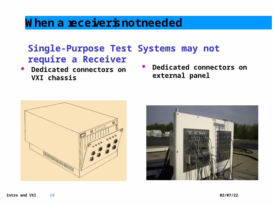
When a receiver is not needed
Dedicated connectors on VXI chassis
Dedicated connectors on external panel
Single-Purpose Test Systems may not require a Receiver
04/10/23Intro and VXI 20
Direct Connect or Hinged Direct Connect shortens cables, reduces capacitance, path resistance
Hinged Assembly provides service loop
04/10/23Intro and VXI 21
VXI Bus Consortium 2008
VXIbus Consortium owns, develops and promotes the VXI standard
New Officers, Exec. Director, and members in last two years
Working on advances to the VXI Specification VXI 4.0 Technical Working Group
Four pillars of VXI messaging Well Conceived – Created by leading test and measurement
companies, the VXI bus is a well defined and open industry standard.
Established – With a 21 year history of success, VXI has established itself as the most prevalent modular instrumentation bus.
Time Tested – VXI is the de-facto standard for applications that have long life cycle requirements. The VXI bus provides system designers the security of knowing that their test platform will outlive the device it was originally designed to test.
Thriving – As significant investment in the new development on the platform continues, VXI is thriving. Its flexibility allows VXI to play a key role in hybrid systems that also PXI, LXI, and GPIB components.
04/10/23Intro and VXI 22
VXI Bus Consortium 2008
Marketing Promotion of the VXI standard Website re-design and content renewal in last two years (
www.vxibus.org) VXI Newsletter VXI Panel at AUTOTESTCON 2008:
• VXI Current and Future Panel – 1:15-3:00 PM – Wed., Sept. 10th
– Moderator• Bob Helsel, Executive Director –
VXIbus Consortium, PXI Systems Alliance, LXI Consortium• Director of Services - IVI Foundation
– Panelists• Charles Greenberg, Technical Working Group Co-Chair,
VXIbus Consortium (EADS)• Fred Bloennigen, Bustec – representing Torsten Rissel,
Technical Working Group Co-Chair, VXIbus Consortium (Bustec)
• Tom Sarfi, President, VXIbus Consortium (VXI Technology, Inc.)
VXI is alive and well! Promotion of >20 new VXI products in the last two years
Technical Working Group Co-Chairs: • Charles Greenberg, EADS-NA Defense & Torsten
Rissel, Bustec Executive Director & Marketing Working Group
Chair: • Bob Helsel, Bode Enterprises, LLC
04/10/23Intro and VXI 24
The Evolution To VXI 4.0
Survey results: In January, 2007, the VXIbus consortium surveyed all consortium members about some proposed VXI enhancements. Fourteen member companies responded:
04/10/23Intro and VXI 25
What Application Spaces Benefit from VXI 4.0?
Digital Test: Need more power and throughput for today’s high speed serial and parallel bus architectures
Data Acquisition: Need more cumulative throughput across the communications bus
RF and Synthetics: Need more power and high speed paths between measurement and processing blocks
Military Test Systems: New systems like eCASS need existing VXI features plus hot-swap, more throughput and power
04/10/23Intro and VXI 26
The VXI 4.0 Technical Working Group
Technical Working Group was given the green light by the VXI board to move forward with 4.0 development.
Agilent Technologies, Bustec, EADS NA, National Instruments and VXI Technology all approved this motion
More participating companies are encouraged to participate. All have a stake in the platform’s direction
04/10/23Intro and VXI 27
The Benefits of the Specification Update
Protects Your Investments: A newly relevant specification adds capability to VXI applications while maintaining backward compatibility with previous revisions
Provides a Future Path: Most powerful modular instrument platform…period
Promotes VXI: The bus you can trust for solutions to DEMANDING electronics test
Produces Solutions: Extends the VXI track record as the primary test solution when:
The price of failure is very high The products that are being tested have a long
life cycle and need a test platform is not prone to obsolescence
Reduced size, open standard, interoperable, fast, and cost-effective solution required
C-size VXI is the perfect card geometry
04/10/23Intro and VXI 28
Goals of VXI 4.0
5-Row Connector Compatible with Legacy VXI Increases power capability and flexibility Incorporates 2eSST for 320MB/s parallel
transfer VITA-41 (VXS)
Remain compatible with all Legacy VXI Increase cumulative throughput to 48 GB/s
(GenII) Compatibility with cPCI, PXI & PXI Express
with simple adapters and VME for DSP/CPU, etc.
Optional VXS Live Insertion Compliance (Hot-Swap)
04/10/23Intro and VXI 29
VXI 4.0 Summary
Proposed VXI enhancements would make VXI the world’s most powerful instrumentation bus for many years to come
It would be fully backwards compatible with existing VXI modules
Transparent support for VITA-41 (VME), PXI and PXI Express modules with no software changes
A high-end packaging solution for military/aerospace test, high-speed digital, RF, synthetic, and data acquisition applications